the Creative Commons Attribution 4.0 License.
the Creative Commons Attribution 4.0 License.
 | 10 Jul 2025
A scaling methodology for the Hybrid-Lambda Rotor – characterization and validation in wind tunnel experiments
Vlaho Petrović
Martin Kühn
The Hybrid-Lambda Rotor is an aerodynamic rotor concept that enables low-specific-rating offshore wind turbines in order to increase the power output in light winds and to limit the loads on the very long and slender rotor blades in strong winds. In this paper, the rotor concept is scaled to wind tunnel size and validated under reproducible inflow conditions. The objectives are to derive a scaling methodology, to investigate the influence of the steep gradients of axial induction along the blade span, and to characterize the wake of the Hybrid-Lambda Rotor in wind tunnel experiments. The scaling objectives are to match the axial induction distribution and to incorporate the change in the angle of attack distribution when switching between the light-wind and strong-wind operating mode. The derived model rotor with a diameter of 1.8 m is experimentally investigated and compared to a conventional model wind turbine in the large turbulent wind tunnel in Oldenburg under tailored inflow conditions produced with an active grid. A two-dimensional laser Doppler anemometer is used to measure the axial induction in the rotor plane, and the wake is characterized by means of a hot-wire rig. The measurement data are supplemented with free-vortex wake simulations of both scaled rotors. The results demonstrate that switching the operating modes with the characteristic change in the angle of attack distribution works similarly for the model and the full-scale turbine. The strong gradients of axial induction along the blade span lead to complex three-dimensional flow structures, such as an increased radial flow component in the rotor plane. The low-induction design of the outer part of the rotor reduces the load overshoots in gust events compared to the conventional model turbine. The wake characterization reveals an outer annulus with reduced wake deficits, an additional shear layer and vortex system, and overall reduced wake deficits over a wide range of wind speeds below rated power. The derived results can improve the understanding of the unique flow patterns that are introduced by the Hybrid-Lambda Rotor and provide a valuable complementary data set to the simulations on the full-scale rotor.
- Article
(9144 KB) - Full-text XML
- BibTeX
- EndNote


The large-scale employment of offshore wind energy is one of the main pillars used to fight climate change. However, integrating more and more conventional wind turbines in the energy grid will lead to an oversupply of power feed-in during strong winds, while a deficit still remains in light winds. This effect is often named self-cannibalization of wind energy (López Prol et al., 2020) as it is self-amplifying with the share of wind energy in the overall energy mix. It is further intensified by the effect of large cluster wakes, which will significantly reduce the efficiency of many wind farms, especially in light winds and in the context of limited available offshore sites and very close spacing of wind farm clusters (Dörenkämper et al., 2023; Schneemann et al., 2020). Self-cannibalization leads to high prices of electricity during light-wind days and low to zero (or sometimes negative) prices during strong-wind days, as predicted by May et al. (2015). Thus, there is a need for wind turbines that produce more power in light winds. Onshore, this aim is usually accomplished by means of larger rotor diameters in relation to the rated power, i.e. so-called low specific power (Swisher et al., 2022). The increasing length and mass of the blades result in loads that are no longer technically feasible, which consequently leads design and control engineers to apply load-limiting techniques. The purpose is to reduce the extreme loads close to rated wind speed, but feasible solutions come with a loss in aerodynamic efficiency and thus reduced power. At offshore sites in particular, this contradicts the higher annual average wind speed since a large portion of the energy yield would be achieved in wind speed regimes with reduced aerodynamic efficiency. There is a need for novel design and control methodologies that enable large offshore rotors with low specific ratings. Such concepts limit the power losses due to load-limiting strategies, which can go hand in hand with techniques that reduce the wake losses.
For this purpose, the Hybrid-Lambda Rotor concept for offshore turbines was developed by Ribnitzky et al. (2024). It features a rotor design for two tip speed ratios (TSRs) and a non-uniform axial induction distribution along the blade span. To limit the loads, the blades are pitched towards feather before rated wind speed, and, in addition, the rotor is switched to a strong-wind mode. Here, the rotor is operated at a lower TSR and a lower axial induction, and the spanwise angle of attack distribution is tilted with a decreasing trend towards the blade tip. When limiting the loads to a certain constraint, this novel combination of blade design and control strategies was proven to cause lower losses in power production compared to conventional blade designs and load-limiting strategies, such as solely pitching the blades to feather.
In previous studies, Ribnitzky et al. (2022) investigated the rotor concept with standard simulation methodologies such as the blade element momentum (BEM) theory. This theory relies on the assumption of independent blade elements. The rotor design with the steep gradients of the axial induction distribution along the blade span consequently reaches the limits of the applicability of the BEM theory. In subsequent investigations, Ribnitzky et al. (2023) analysed the concept using free-vortex wake (FVW) simulations and large-eddy simulations (LESs), and the results were compared to the BEM theory. Although reasonable agreement was found for rotor-integrated quantities like power, thrust, and blade root bending moment, discrepancies were noticed in the spanwise-resolved variables, like the axial induction and the angle of attack distributions. Those studies further revealed a second shear layer in the wake that trails from the mid-span blade region with the steep gradients. This raises interesting questions about the blade aerodynamics and the wake of such a rotor. To consolidate the findings from the simulation-based studies, an experimental validation of the Hybrid-Lambda Rotor concept is lacking. This leads us to the question of how the rotor concept can be scaled to wind tunnel size.
Designing a model wind turbine blade for use in a wind tunnel usually aims to replicate certain physical characteristics of a full-scale rotor. This process involves finding a delicate compromise since an exact match of all relevant physical parameters between the model and the full-scale turbine is usually not possible. Canet et al. (2021), Bottasso and Campagnolo (2021), and Gasch and Twele (2012) thoroughly analyse the scaling of wind turbines in general. Scaling the Hybrid-Lambda Rotor involves four major challenges. First, the large geometric scaling factor of ; second, the high design TSR of 11 of the full-scale rotor; third, the non-uniform distribution of the axial induction along the blade span; and, fourth, the ability to change between a light-wind and a strong-wind operating mode. The first two aspects can lead to very low chord lengths, which is a challenge for manufacturability and which leads to very low Reynolds numbers. This would result in an undesired change in the airfoil polars and a loss in aerodynamic efficiency. The latter two aspects require a delicate blade design for two main operating conditions that can mimic the characteristics of the Hybrid-Lambda Rotor even in the small-scale environment of a wind tunnel. In this study, the emphasis is on the aerodynamic effects. Consequently, the model blades are designed over-proportionally stiff to separate aerodynamic effects from aero-elastic interactions. Further, the design and application of a transient controller for the wind tunnel model will be addressed in future studies.
Once successfully designed and manufactured, a wind tunnel model could provide valuable insights into the influence of the steep gradients of the axial induction along the blade span. It further allows us to explore the possibilities of changing the operating modes and changing the spanwise angle of attack distribution, and it enables an in-depth characterization of the wake of the Hybrid-Lambda Rotor. Wang et al. (2021) showed that wakes of scaled wind turbines can deliver a very good representation of the full-scale counterpart, with minor exceptions due to nacelle effects in the inner near-wake region. The study presented here gives valuable insights into aerodynamic effects and design methods for low-specific-rating wind turbines. This includes an understanding of the flow in the rotor area and in the near wake of rotors with a non-uniform axial induction distribution. Further, the study can serve as an example for various complex scaling problems in wind energy research and provides guidelines and inspirations for designing scaled model turbine blades for aerodynamic investigations in the wind tunnel.
Further innovative rotor concepts have been developed in the wind energy research community. A non-uniform spanwise load distribution of the rotor can lead to enhanced wake mixing, according to Kelley et al. (2014) and Yang et al. (2015). They investigated blade designs with larger spanwise gradients of bound circulation with FVW simulations and LESs and found that those rotors exhibit shorter and faster mixing far wakes. Dong et al. (2023) compared the wake of rotors with different spanwise load distributions and found that the wake recovery rate is higher for a blade design with a load distribution that is shifted more towards the blade root. Low-specific-rating turbines that operate at lower thrust coefficients over a wide range of wind speeds can have additional advantages on a wind farm level (Madsen et al., 2020). Further rotor concepts that aim to enhance wake diffusion also exist. Knauer (2021) introduced a rotor design with a nearly inverse axial induction distribution compared to the Hybrid-Lambda Rotor, using a ventilation area with negative axial induction close to the blade root to introduce a small jet of relatively high wind speeds into the rotational centre of the wake.
The overall objective of this paper is to experimentally characterize and validate the aerodynamic design concept of the Hybrid-Lambda Rotor under reproducible, turbulent, and transient inflow conditions on a wind tunnel scale. More specifically, the contribution aims to (1) develop a method on how to scale the Hybrid-Lambda Rotor concept to wind tunnel size, (2) investigate the influence of the steep gradients of axial induction along the blade span on the aerodynamics, and (3) characterize the near wake of the Hybrid-Lambda Rotor.
In this section, we scale the Hybrid-Lambda Rotor with a rated power of 15 MW and a diameter of 326 m (Ribnitzky et al., 2024) to the size of the Model Wind Turbine Oldenburg with a diameter of 1.8 m (MoWiTO 1.8). The model turbine is usually operated with a conventional set of blades, as described in Berger et al. (2018, 2021). This rotor is an aerodynamically scaled version of the NREL 5 MW reference turbine, defined by Jonkman et al. (2009), scaled under the objective of maintaining the design TSR and the lift distribution along the blade span, and it serves as a reference rotor for this study.
2.1 Geometric scaling vs. aerodynamic redesign
The scaling methodology for the Hybrid-Lambda Rotor presented here differs from the aforementioned scaling approach of the reference rotor. The Hybrid-Lambda design methodology, as described by Ribnitzky et al. (2024), aims to increase the rotor diameter compared to a reference rotor in order to increase the power in light winds. In contrast, the scaling approach presented here aims to have the same rotor diameter as the reference model turbine (1.8 m). This ensures similar boundary conditions in the wind tunnel between the two rotors, considering rotor aerodynamics and wake extension. The most straightforward approach to deriving a scaled model would be a geometric downscaling of the full-scale blade. Scaling the Hybrid-Lambda Rotor from a diameter of 326 to 1.8 m leads to a length scaling factor of , where D is the rotor diameter and the subscripts m and f refer to the model turbine and full-scale turbine, respectively. An exact geometric downscaling would lead to a chord length at the tip of only 8 mm and an unfeasibly low blade thickness of 0.8 mm. Further, if the internal blade shape were scaled exactly, this would lead to a blade mass of only 24 g and a tip deflection under rated conditions of 14 cm. Clearly, these values illustrate that a geometrical downscaling is not an option. Besides manufacturing constraints, the short chord length would lead to very low Reynolds numbers of about 37 000 at the blade tip at rated power, resulting in non-negligible changes in the airfoil polars and unacceptable losses in the aerodynamic efficiency. Consequently, an aerodynamic redesign of the blade is necessary. This means a new blade shape is defined that matches some pre-defined characteristics of the full-scale rotor. Choosing different airfoils and a new chord and twist distribution leads to a visually different blade, which is, however, completely irrelevant as long as the relevant aerodynamic properties are reasonably matched. The first step is to properly define the scaling objectives and to choose the aerodynamic characteristics that should be matched, since, as previously mentioned, not all characteristics can be fulfilled at the same time.
2.2 Scaling objectives
Common scaling approaches aim to replicate the TSR and the non-dimensional spanwise circulation distribution. However, the aforementioned challenges forced us to partially deviate from this approach. In contrast, in this study we focused on matching the axial induction distribution along the blade span for the light-wind and strong-wind operating modes of the full-scale Hybrid-Lambda Rotor, and we adapted the operational TSRs. Further, we aimed to incorporate the possibility to change the operating mode and, consequently, to tilt the angle of attack distribution, similar to the full-scale rotor. More precisely, tilting the angle of attack distribution during the transition from the light-wind (LW) mode to the strong-wind (SW) mode means that the angle of attack is lowered in the outer part of the blade but increased for the inner part. With the focus on aerodynamic investigations, we decided to design the model blades over-proportionally stiff in order to exclude elastic effects and unintended fluid–structure interactions that could overshadow fundamental effects resulting solely from the novel blade design methodology.
2.3 Adaptation of design TSRs
An application of the design TSRs of 11 and 9 from the full-scale rotor is not feasible for the wind tunnel size, as the derived chord lengths and local Reynolds number (Re) would be too low, even with the choice of new airfoils. Using Eqs. (1)–(4), we explain why a reduction in design TSR will increase the Reynolds number. The latter is defined by Eq. (1).
Here, ρ is the air density and η is the dynamic viscosity, which are both usually constant across full-scale and wind tunnel applications. The relative velocity at the respective blade element urel is proportional to the inflow velocity u∞ and the design TSR λd, as denoted in Eq. (2). The characteristic length c is the chord length which follows the trends as expressed in Eq. (3) according to a Betz blade design, as described by Gasch and Twele (2012). Here, R is the rotor radius, B is the number of blades and Cl,d is the design lift coefficient. Consequently, Re scales with the reciprocal of λd, as denoted in Eq. (4), and larger Reynolds numbers can be achieved by reducing the design TSR and choosing a low design lift coefficient.
The design TSRs from state-of-the-art model wind turbines range from 4.5 to 7.5. Examples include model wind turbines that are scaled for aero-servo (and potentially elastic) investigations, such as the MoWiTO 1.8 (Berger et al., 2018), the TU Munich G2 (Bottasso et al., 2014), and the Polimi model turbine (Bayati et al., 2016) with a design TSR of 7.5. Model turbines that are designed for wake (and potentially wind farm) investigations are the TU Munich G1 (Campagnolo et al., 2016) with a design TSR of 7, the NTNU (Krogstad and Lund, 2012), and the MoWiTO 0.6 (Schottler et al., 2016) with a design TSR of 6. Even lower design TSRs of 5 and 4.5 are chosen for model turbines with smart blade applications, such as the TU Delft (Hulskamp et al., 2011) and the TU Berlin (BeRT) (Soto-Valle et al., 2020) turbines. Models with large diameters, like the MEXICO rotor (Schepers and Snel, 2008) or the NREL phase VI turbine (Hand et al., 2001), with diameters of 4.5 and 10 m, are also designed for relatively low TSRs of 6.7 and 5.4, respectively.
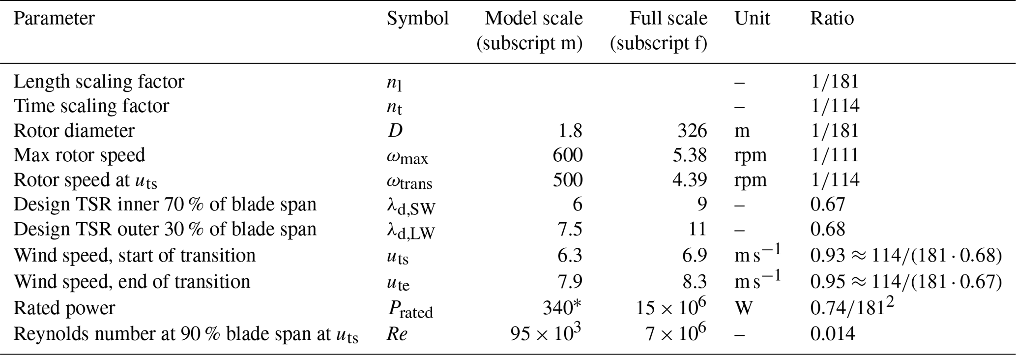
Consequently, we decided to reduce the design TSRs of the Hybrid-Lambda Rotor for the wind tunnel model. Within the iterative design process, several TSRs were investigated. We found that a design TSR for the light-wind mode λd,LW=7.5 works well in order to fulfil the constraints of minimal chord length (3 cm) and Reynolds number (70 000). Further, there is the advantage of the comparability with the conventional blades for the MoWiTO 1.8, as they feature a design TSR of 7.5, too. The design TSR for the strong-wind mode λd,SW was chosen in order to incorporate a similar change in the inflow angle distribution to that of the full-scale rotor when switching from the light-wind to the strong-wind mode. The aforementioned change can be calculated with Eq. (5) and is visualized in Fig. 1 using the axial induction distribution from the full-scale rotor. Here, aSW and aLW are the induction factors in the strong-wind and light-wind modes, respectively.
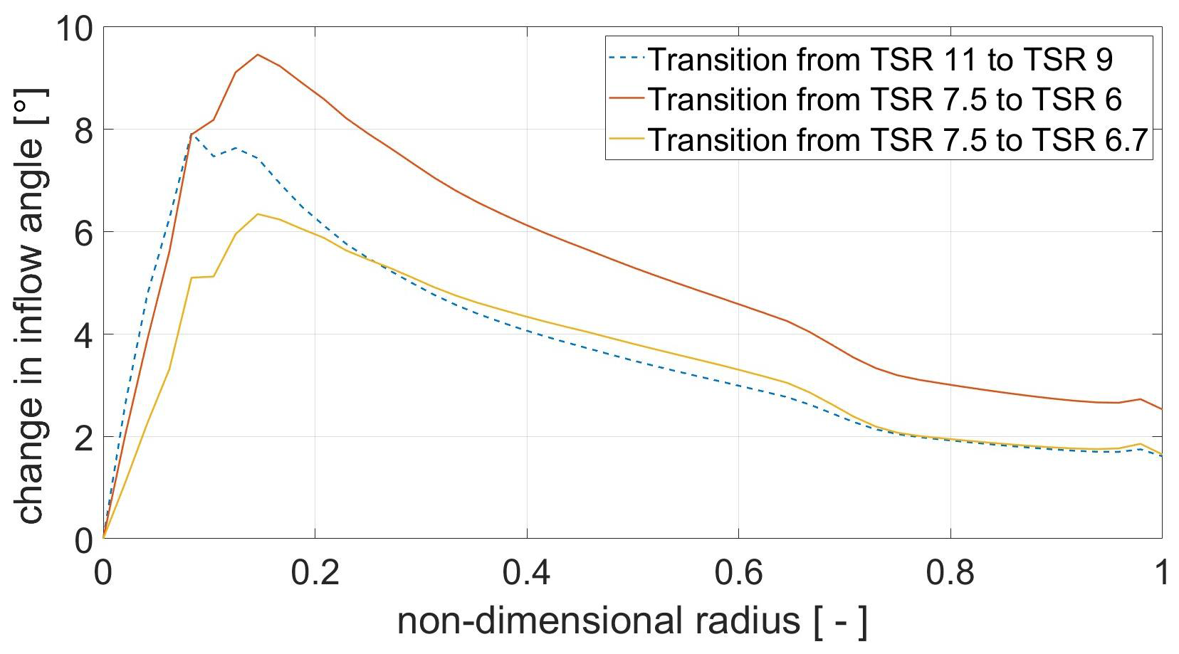
Figure 1Change in the inflow angle distribution for operational transition of TSRs, with the full-scale rotor represented with the dashed line.
It can be readily seen that a reduction of the TSR from 7.5 to 6.7 would lead to a similar change in the inflow angle compared to a reduction from 11 to 9 (as for the full-scale rotor) in the relevant blade region, except for the segments close to the blade root. However, we chose the strong-wind TSR to be 6 for two reasons. First, we want to enlarge the effect of the change in the angle of attack distribution in order to facilitate the measurability with the background of measurement uncertainties. Second, the transition from the light-wind to the strong-wind mode at a constant rotational speed will expand over a wider range of wind speeds if the design TSRs are further apart. For instance, with the start of the transition region at uts=6.3 m s−1, the tip speed ratio in the strong-wind mode of λd,SW=6.7 would lead to the end of the transition region at ute=7.0 m s−1, whereas a lower tip speed ratio λd,SW=6 would result in a wider transition region with ute=7.9 m s−1. This opens up more opportunities for control-related investigations in the wind tunnel that focus on the transition between the operating modes.
2.4 Design and scaling constraints
With the choice of design TSRs being made, the design process continues with the application of the Hybrid-Lambda design methodology, which is visualized in Fig. 2. However, certain constraints need to be taken into account. The Reynolds number should be at least 70 000, as suggested by Bottasso and Campagnolo (2021), to limit the reduction in aerodynamic efficiency. The chord length directly influences the Reynolds number. In addition, the constraint of the minimal chord length due to manufacturing reasons is set to 3 cm. This is not a strict limit, but it is related to the minimal leading edge radius and the minimal trailing edge thickness of 0.5 mm within the milling process of the blade mould. The smaller the chord length, the larger the adjustments that need to be applied to the airfoil shape in order to maintain the constraints for the leading edge radius and trailing edge thickness. The blade root diameter is constrained to 35 mm in order to include the same pitch actuation mechanism and the same blade root connection to the hub as is used for the conventional blades. In theory, the maximum flapwise blade root bending moment (RBM) scales with . With a maximum value for steady inflow of 62.9 MNm for the full-scale model, this would result in a value of 10.6 Nm for the wind tunnel model. This is the load level where the transition from the light-wind to strong-wind mode takes place in a steady-state assumption. However, under transient inflow conditions, higher loads are expected. Due to the load-limiting constraints of the MoWiTO 1.8, we lowered the design value for the steady-state maximum flapwise RBM to 7.5 Nm. The operational range of the rotational speed must be between 420 and 600 rpm. It is constrained by the first tower eigenfrequency (6.7 Hz) at the lower end and by the maximum rotational speed of the slip ring in the drive train at the upper end.
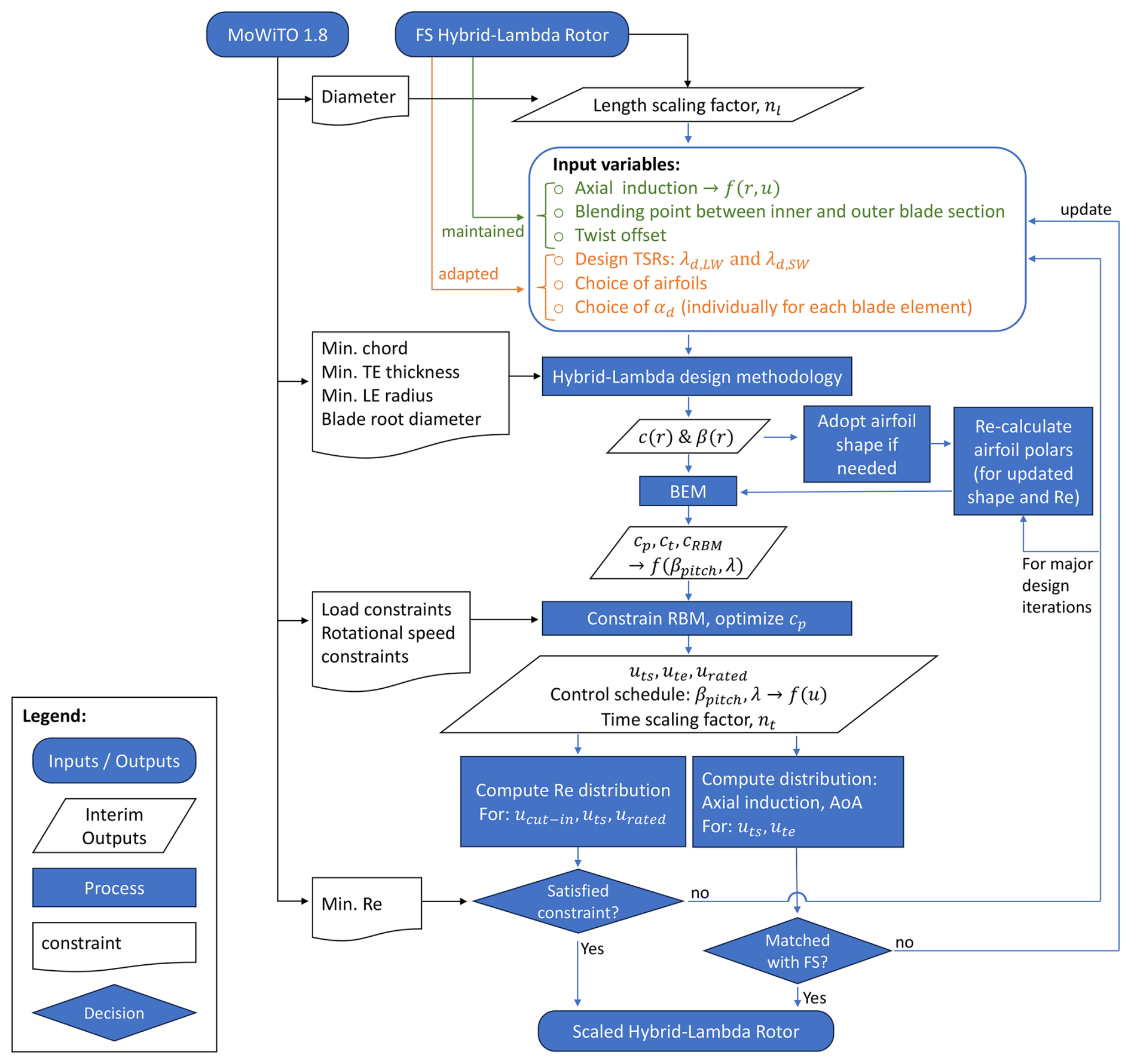
Figure 2Scaling and design workflow for the Hybrid-Lambda Rotor. AoA – angle of attack; αd – design angle of attack; β – twist angle; βpitch – pitch angle; c – chord length; cp, cT, and cRBM – power, thrust, and flapwise root bending moment coefficients; f(…) – as a function of (…); FS – full scale; LE – leading edge; LW – light wind; λ – tip speed ratio; r – local radius; Re – Reynolds number; SW – strong wind; TE – trailing edge; ucut-in, uts, ute, and urated – wind speeds at cut-in, start of transition, end of transition, and rated power.
2.5 Inputs to the aerodynamic redesign
Before starting the design process, appropriate airfoils need to be chosen. We investigated several low-Reynolds-number airfoils and decided to use the SG6040 and SG6041 airfoils (Giguere and Selig, 1998), which were also used for the conventional blades of the MoWiTO 1.8, for the sake of comparability. The polars are simulated with XFoil for the individual blade element with the respective Reynolds number with an Ncrit value of 7 and without a forced transition. Ncrit is the critical amplification factor that describes the transition between laminar and turbulent flow over the airfoil.
Next, the Hybrid-Lambda design methodology, as described by Ribnitzky et al. (2024), is applied with the following input variables. The design TSRs are set to 7.5 and 6, as explained above. Identical to the full-scale rotor, the blending region between the inner and outer blade section is set to 70 % blade length (equivalent to 73 % rotor radius for the model turbine), and the twist offset for the inner blade region is set to −2.5°. Further information on the twist offset within the Hybrid-Lambda design methodology is given by Ribnitzky et al. (2024). The desired axial induction distribution is adopted from the full-scale rotor, since this is the major scaling objective. The design angle of attack (αd) is derived from a compromise between achieving good lift-to-drag ratios (αmax,L/D≈4.5°), maintaining reasonable margins to the stall region (αstall≈11.5°), and maintaining low lift coefficients that help to fulfil the minimum Reynolds number and chord length constraints. Consequently, the design angle of attack is set close to the maximum lift-to-drag ratio for the inner part of the blade where the low design TSR already ensures large enough chord lengths. For the outer part of the blade, the design angle of attack is reduced in order to enlarge the chord length, which also matches well with the angle of attack distribution of the full-scale rotor. With these input variables, the chord and twist distribution can be calculated. Those are shown in Fig. 3 for the final blade design.
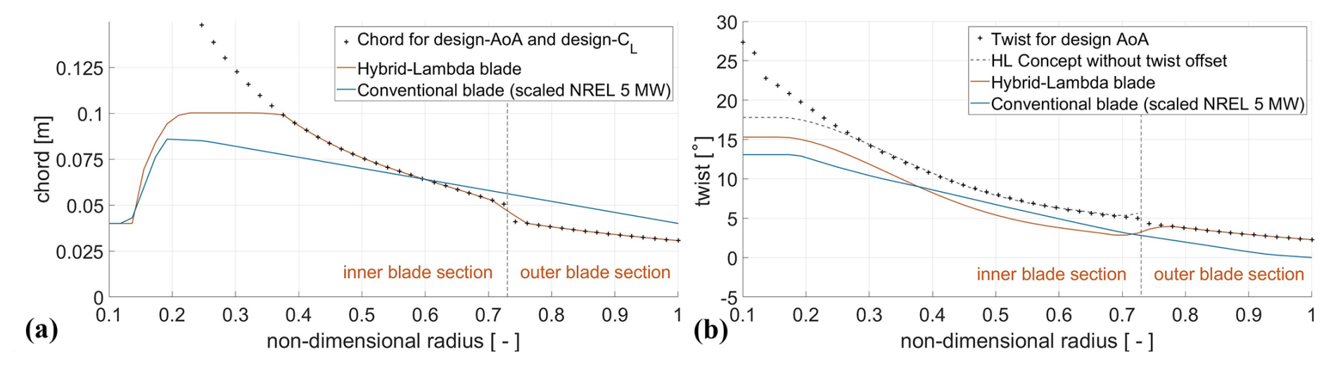
Figure 3Chord (a) and twist distribution (b) for the scaled Hybrid-Lambda Rotor and the scaled NREL 5 MW turbine.
2.6 Deriving the control schedule and time scaling factor
BEM simulations with steady and uniform inflow provide the aerodynamic performance curves, such as the power coefficient cp, thrust coefficient cT and flapwise RBM as a function of pitch angle βpitch, and operational TSR. Now, the constraint of flapwise RBM is applied, and the wind speed is calculated at which the limiting loads are reached (uts), which is defined as the start of the transition region. The control strategy, i.e. rotational speed and pitch angle over wind speed, as shown in Fig. 4 for the final scaled design, is derived as follows. For wind speeds greater than uts, the rotational speed is kept constant until λSW is reached. Then the rotational speed follows λSW until rated wind speed. The pitch angle is set in order to constrain the RBM below rated wind speed with the given operational TSRs. The wind speed at which the transition to the strong-wind mode starts, uts, and the speed at which it ends, ute, are now known, as well as the respective pitch angles. Since most of the measurements are performed at these two wind speeds and with the respective rotational speed, ωtrans, we define the time scaling factor as
Note that the maximum rotational speed of 600 rpm is set by hardware constraints and is not exactly true to scale compared with the full-scale model. An overview of the actual turbine parameters and the scaling factors is provided in Table 1. Note that since we transferred the Hybrid-Lambda concept to lower TSRs, the scaling of the wind speed, which would be defined as , does not hold true in this case. However, if we define the scaling ratios of the design TSRs as
then the wind speeds can be derived from Eqs. (8) and (9):
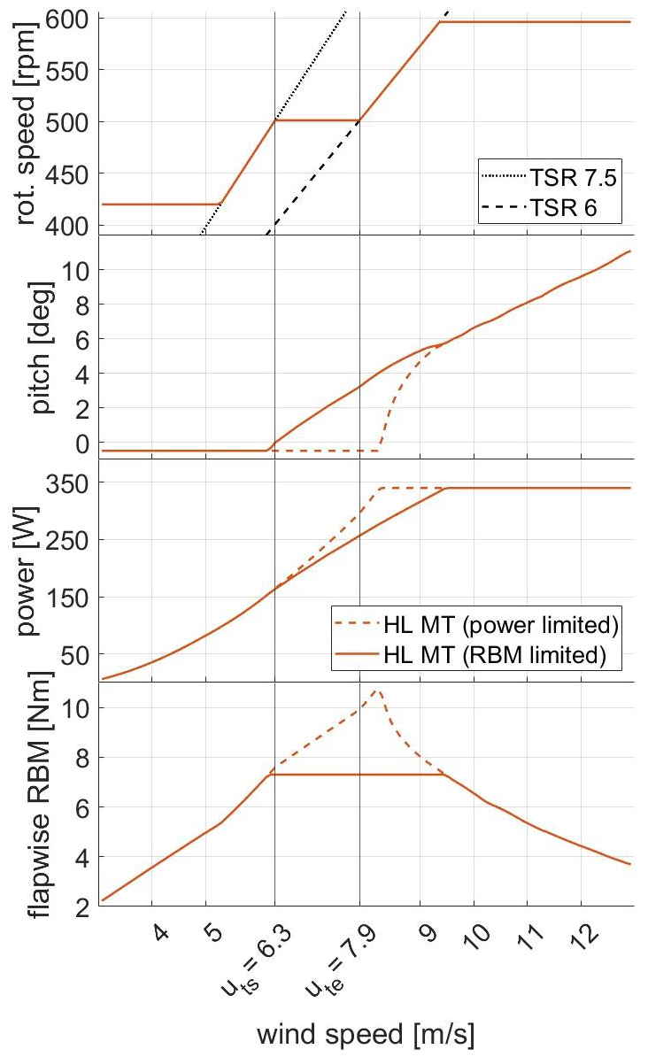
Figure 4Control schedule for the Hybrid-Lambda model turbine (HL MT), derived from BEM simulations.
Table 1General parameter of the wind tunnel model and the full-scale Hybrid-Lambda Rotor.
∗ Reduced due to hardware constraints.
2.7 Verifying the constraints and closing the design loop
Finally, we can check the angle of attack and axial induction distribution for the two operating points (uts and ute), and we can verify the scaling objectives as follows. Is the axial induction distribution from the full-scale rotor reasonably matched (Fig. 5a)? Is the change in the angle of attack distribution reasonable when switching the operating modes (Fig. 5b)? Is the constraint for the Reynolds number achieved (see Fig. 6)? If one of these objectives is not met, the design optimization loop is closed by re-tuning the input parameters and calculating the next design iteration. For major design updates, we re-calculate the airfoil polars as follows. The minimum leading edge radius and trailing edge thickness is constrained due to manufacturing reasons. Consequently, the airfoil shape needs to be adapted for all blade elements where the derived chord length would lead to a violation of the constraints. Now that the relative velocity at the respective blade element is known from the BEM simulations, the airfoil polars can be re-calculated for each individual blade element, considering the expected Reynolds number and the modified airfoil shape. The largest adaptation to the airfoil shape is necessary for the blade element with the shortest chord length, consequently, at the blade tip. We observed an increase in the drag coefficient for angles of attack greater than 3.5°, which results in a reduction in the maximum lift-to-drag ratio by 15 % compared to the unchanged airfoil. These numbers highlight the importance of considering the modifications to the airfoil shape, since the effect is happening in the relevant region of operational angle of attacks.
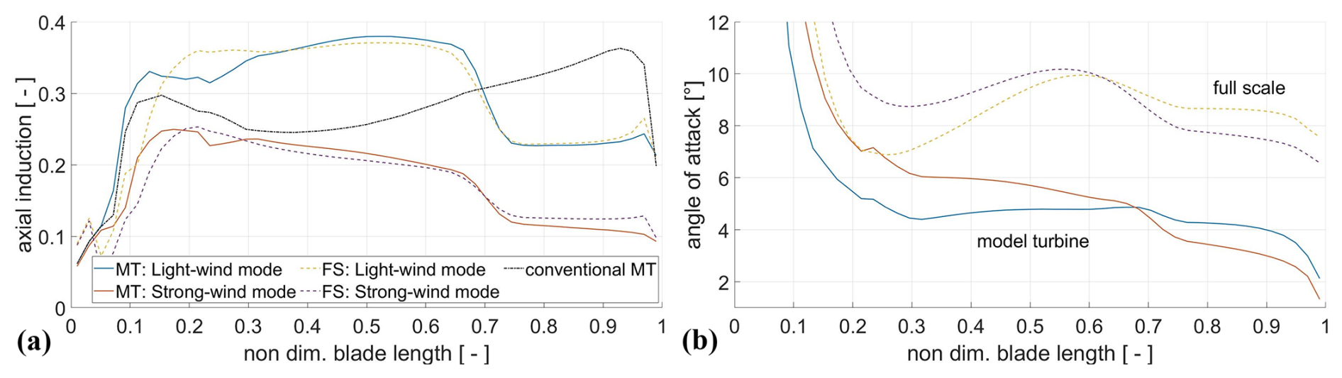
Figure 5Axial induction (a) for the light-wind mode (at uts) and the strong-wind mode (at ute) for the Hybrid-Lambda model turbine (MT), the full-scale (FS) rotor, and the conventional model turbine in BEM simulations and respective angle of attack distributions (b).
In this section, we first explain the experimental set-up in Sect. 3.1, the measurement equipment in Sect. 3.2, and the post-processing of the measurement data in Sect. 3.3. Several simulations are used to derive the blade design of the scaled model, for comparison of the experimental data with simulation models and to get further insights into flow quantities that could not be measured. The simulation methodology is therefore described in Sect. 3.4.
3.1 Experimental set-up
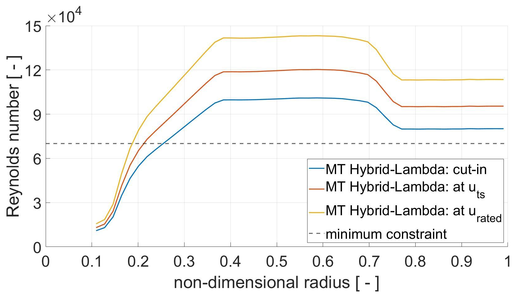
The experiments were carried out in the turbulent wind tunnel of Oldenburg, further described by Kröger et al. (2018). It is a Göttingen-type wind tunnel, featuring a rectangular nozzle with a cross section of 3 m×3 m and a test section length of 30 m. For the purpose of this study, the open-jet test section configuration was used, as illustrated in Fig. 7. The wind tunnel can be equipped with an active grid to realize turbulent, reproducible flow patterns in the inflow, as further explained by Neuhaus et al. (2021). The active grid was mounted with a static open-flap configuration for the investigations of the rotor-integrated quantities (Sect. 4.1), the radially resolved measurements (Sect. 4.2), and the wake measurements (Sect. 4.4). This leads to a steady, uniform inflow over the rotor area with a turbulence intensity (Ti) of approximately 2 %, which is used for all presented measurements if not stated differently. For the wake investigations only, four different levels of turbulence intensity (2 %, 4 %, 6 %, and 8 %) were generated with the active grid. To analyse the effect of gusts on the rotor (see Sect. 4.3), the active grid was used to produce a transient wind speed change that is intended to represent a scaled operating gust, as described by Neuhaus et al. (2021). According to the IEC 61400-1 (2019) standard, the gust should last 10.5 s. With the time scaling ratio of 1:114 (as defined in Sect. 2), the ideally scaled gust in the wind tunnel would last only 0.09 s. Unfortunately, controlling the wind speed at such high frequencies is not possible, and there is always a trade-off between high frequencies and sufficient wind speed amplitudes. Neuhaus et al. (2021) found the fastest gust with a reasonable gust amplitude has a duration of 0.75 s. This means that the gust in the wind tunnel is about 8 times slower than the full-scale equivalent. The amplitude reaches from 6.3 to 7.5 m s−1 in the wind tunnel, while the IEC operating gust ranges from 6.3 to 8.2 m s−1.
Figure 7Experimental set-up, side (a) and top view (b), indicating the measurement positions of the hot wires, LDA, and Prandtl tube. The coordinate system is located in the rotor centre. MoWiTO 1.8 with the Hybrid-Lambda blades (c), D=1.8 m, hub height of 1.5 m.
In addition to the experiments with the Hybrid-Lambda Rotor, further measurements were carried out with the conventional blades to compare the load response due to gust events (see Sect. 4.3) and to compare the wake of the two rotor designs (see Sect. 4.4). Both model rotors have the same diameter of 1.8 m. The model turbine, as depicted in Fig. 7, is equipped with strain gauges in the blade root to measure the flapwise blade root bending moment and in the tower base to derive the rotor thrust. A torque meter and a rotational encoder in the drive train allow for measurements of the rotor torque, azimuthal position, and rotational speed. The data acquisition system of the model turbine samples the aforementioned measurement data at 5 kHz. The blade pitch is set by three DC motors, mounted in the blade roots, allowing for individual pitch control. However, in this analysis, only collective pitch settings are used.
For this study, the turbine is operated at a fixed rotational speed of 500 rotations per minute (rpm). Changing the rotational speed would influence the operational Reynolds number, which affects the aerodynamic behaviour of the turbine. For the sake of comparability between all conducted measurement runs, a fixed reference rotational speed is chosen. For the gust investigations, the rotational speed and the blade pitch are also set to constant values. Since the focus of this study is on the aerodynamic behaviour and the impact of the different blade designs, no overshadowing of the effects by controller actions is desired.
The model turbine is placed 4.8 m (2.66 D) behind the wind tunnel nozzle, and the inflow velocity is measured with a Prandtl tube and a pressure transducer 2.1 m (1.2 D) behind the nozzle. These values were found to be best practice in order to avoid influences of the induction zone of the model turbine on the wind speed measurements and on the development of the inflow behind the active grid.
3.2 Measurement equipment and experimental matrix
To measure the axial and tangential induction, a two-dimensional laser Doppler anemometer (LDA) with a power of 1 W for each laser is used. A beam expander with a focus length of 2.1 m allows the LDA system to be mounted at a reasonable distance in order not to disturb the flow. In the radial direction, 16 measurement points are taken at the 3 o'clock position (looking downstream) in order to minimize the tower effects on the measurements (rotor spins clockwise looking downstream). The measurement points cover a range from 0.3 to 0.95 R, with closer spacing in the region of the expected steep induction gradients, as indicated in Fig. 7. The axial and tangential induction and the angle of attack are derived from the method introduced by Herráez et al. (2018) and further applied by Berger et al. (2021). According to this method, the axial and tangential velocity components are probed in the bisectrix of two blades where the local blade induction is counterbalanced and cancelled out. Herráez et al. (2018) found that the trailed vorticity at the blade tip does play a non-negligible role, and measurements further outboard than 0.92 R should be treated with care. This method is only valid for axial and uniform inflow, which is given for the studies presented here.
We analysed the wake of both the conventional and the Hybrid-Lambda Rotor. The light-wind mode of the Hybrid-Lambda Rotor leads to a thrust coefficient of 0.92. The conventional blades are investigated at the same wind speed with the same rotor speed, and the pitch is set in order to achieve the same thrust coefficient as for the Hybrid-Lambda blades in the light-wind mode. Further, the thrust coefficient is 0.61 for the strong-wind mode and 0.45 for rated wind speed. The investigated operating modes are summarized in Table 2. Hot-wire measurements were performed downstream of the rotors at hub height on a horizontal line along the 3 o'clock position. A hot-wire rig with 24 one-dimensional hot wires was used, covering a radial range from the centre of rotation to 1.38 m (0.77 D) with an equidistant spacing of 6 cm (0.033 D). The hot-wire rig was mounted on a traverse to realize a very fine spacing in the downstream direction, too. Measurements are taken at 51 positions downstream of the rotor, from 0.4 to 5.4 m (0.22 D to 3 D) with a spacing of 0.1 m (0.056 D). The first three downstream positions are located next to the nacelle. Overall, this leads to a very high spacial resolution of the wake measurements, resulting in an equidistant grid of 24×51 measurement points covering a rectangle of 1.38 m×5.4 m, which is illustrated in Fig. 7. The hot-wire measurements are sampled with 6 kHz over a duration of 40 s for each point. A different hot-wire rig was used only for the investigation of varying inflow turbulence intensities. In this case, the hot wires were mounted with a spacing of 4 cm, with 16 hot wires ranging from 0.35 D to 0.68 D, and only the downstream position of 0.4 D was investigated.
Table 2Investigated operating modes for the Hybrid-Lambda wind tunnel model.
To characterize the scaled Hybrid-Lambda Rotor and to derive the rotor-integrated quantities, a measurement matrix was performed, which consists of a grid of TSR and pitch combinations with the turbine operating under steady-state conditions. This matrix covers TSRs from 5 to 9 with a spacing of 0.5 and pitch angles from −2 to +4° with a spacing of 1°. Further, a finer grid is applied in the area of the highest interest around the maximum power coefficient. From −1.6 to −0.4°, the pitch angle is varied in steps of 0.4°, and the TSR is varied from 6.75 to 8.5 in steps of 0.25. The combination of very low TSR and pitch values could not be measured since the structural loads would exceed the safety constraints of the model turbine. However, according to the Hybrid-Lambda control strategy, the pitch angle is increased when the TSR is lowered. Consequently, the combination of low TSR and low pitch values is unlikely to be relevant. In total, 91 points were measured. For each point, the turbine data are averaged over 15 s, which corresponds to 125 rotor revolutions. The non-dimensional power and thrust coefficients cp and cT are calculated with the inflow wind speed derived from the Prandtl tube measurements and the density calculated from air temperature, humidity, and ambient pressure. Since all measurements for the rotor-integrated quantities are recorded within 1 d, the maximum variation in the air density was only 0.2 %, and the air density is considered error-free in the error propagation. For the power and thrust coefficients, the error-prone variables are thrust force, rotor torque, inflow velocity, and rotational speed.
3.3 Measurement data post-processing and uncertainty estimation
Certain correction methods are applied to the turbine load measurements, as described in the appendix of Berger (2022). The measured torque is corrected for the drive train friction – resulting from the bearings and the slip ring – in order to derive the rotor aerodynamic torque. The friction is derived as a linear function of rotational speed from calibration measurements, where the drive train is rotated without the blades. The thrust is corrected for the aerodynamic drag on the tower and nacelle. The drag force is derived by wind tunnel measurements with detached blades, resulting in a quadratic correction function of the thrust force over the wind speed. When calculating the wind speed at the location of the tower, induction effects are taken into account within an iterative process according to the momentum theory, as further described by Berger (2022). The strain gauge measurements are post-processed with a zero-phase digital filter, using a Butterworth infinite impulse response low-pass filter with a half-power frequency of 28 Hz, which is 12 % higher than the blade-passing frequency (3P). This ensures that all relevant rotor dynamics are resolved but allows the data to be filtered for high-frequency vibrations and noise.
The LDA measurement data are post-processed as follows. First, the data are synchronized with the azimuth angle measurements of the MoWiTO 1.8. From the continuously acquired LDA data, only the values that lie in a sector of ±3° from the blade bisectrix are further considered. For each radial position, the data are recorded for 60 s, which corresponds to 1500 blade passings. The LDA data are not recorded in equidistant time steps but whenever a seeding particle passes through the probe volume. Due to the nature of the flow, more samples will be available for the axial component compared to the tangential component. On average, 17 000 samples were used for the calculation of the mean value of the tangential velocity and 37 500 samples for the axial velocity, for every radial position. The number of samples was never lower than 14 700 and 29 000 for the tangential and axial velocity components, respectively. Therefore, the confidence in the mean value is very high, and the 95 % confidence interval would not be visible in the plots. Consequently, we decided to plot the standard deviation over all samples, which visualizes the spread of the data but does not represent the high confidence in the mean value. In order to calculate the axial induction, precise information about the inflow is needed. Therefore, the inflow is measured with the LDA along a horizontal line at hub height in the position of the rotor plane with the turbine not installed. These measurements result in an observation of the mean wind speed and the respective standard deviation for all positions where the axial induction should be calculated. The inflow characterization reveals a slight drop in the axial inflow velocity from the centre to the edge of the rotor area of 0.25 m s−1. This marginal non-uniformity is accounted for in the calculations of the axial and tangential induction and the angle of attack, since the information of the inflow at the individual radial position is used, as indicated in Eqs. (10)–(12). Here, a and a′ are the axial and tangential induction factors; uax and uta are the axial and tangential velocity components in the rotor plane; u∞ is the undisturbed axial inflow velocity component in the rotor plane; r is the radial position; ω is the rotational speed; α is the angle of attack; and γ is the geometrical angle between the chord of the local blade segment and the rotor plane, consisting of twist and pitch.
Measurement uncertainties are calculated with the Gaussian error propagation, and, if not stated differently, error bars indicate the combined standard deviation of all measurement uncertainties, as indicated in Eq. (13). Here, ∂ refers to the partial derivative of the respective equation, f(xi) is the combined measurement value that is calculated from n measurement variables xi, and σ is the standard deviation of the respective variable. Unless indicated differently, the latter is derived directly from the measurement data. We assume σ(r)=2 mm and σ(γ)=0.2°.
For the investigation of the gust events in Sect. 4.3, ensemble averaging is performed. The gust event is repeated 45 times with the active grid, which is synchronized with the turbine's data acquisition system. The measurement data of the resulting flapwise blade root bending moment are aligned for all repetitions, and an average value and the standard deviation at each time step of the gust are constructed. This approach can smooth out non-deterministic variations. The same transient inflow conditions were applied to the conventional blades and to the scaled Hybrid-Lambda Rotor. In this case, we use the 95 % confidence interval of the 45 repetitions to indicate the statistical significance of the different behaviours of the two blade sets. For the sake of comparability, we normalize the RBM measurements with the mean stationary value of the respective blade set. However, the difference between the two blade sets in the mean stationary value is only 0.2 Nm, which corresponds to 3 % of the mean value.
3.4 Simulations
The scaled version of the Hybrid-Lambda Rotor was designed with an in-house BEM code, as described in Hansen (2008). The radially resolved axial induction and angle of attack distributions were derived with this simulation tool. In this paper, we define the axial induction as averaged over the annulus, which can be expressed as the local axial induction on the blade multiplied by the tip-loss factor. Additionally, aero-elastic simulations were carried out with OpenFAST v3.1 (Jonkman and Sprague, 2021) for model validation. The rotor-integrated quantities (cp,cT, and flapwise RBM) shown in this study are derived from the OpenFAST simulations. The two abovementioned tools both implement the Prandtl tip and root loss models and the Glauert high thrust correction with the approximation by Buhl (2005). Neither of them uses a dynamic stall or dynamic inflow model, since the reference simulations in this study are restricted to steady and uniform inflow. The tower shadow effect is modelled only in OpenFAST. In preliminary analyses, the blade tip deflection in front of the tower was measured with a laser distance sensor, and it did not exceed 15 mm in steady-state operations. However, the blades are modelled in OpenFAST as flexible using ElastoDyn as the elastic solver (Jonkman and Sprague, 2021). The tower is modelled as rigid for both tools. Since the in-house BEM code is purely aerodynamic, all components are modelled as rigid in this case.
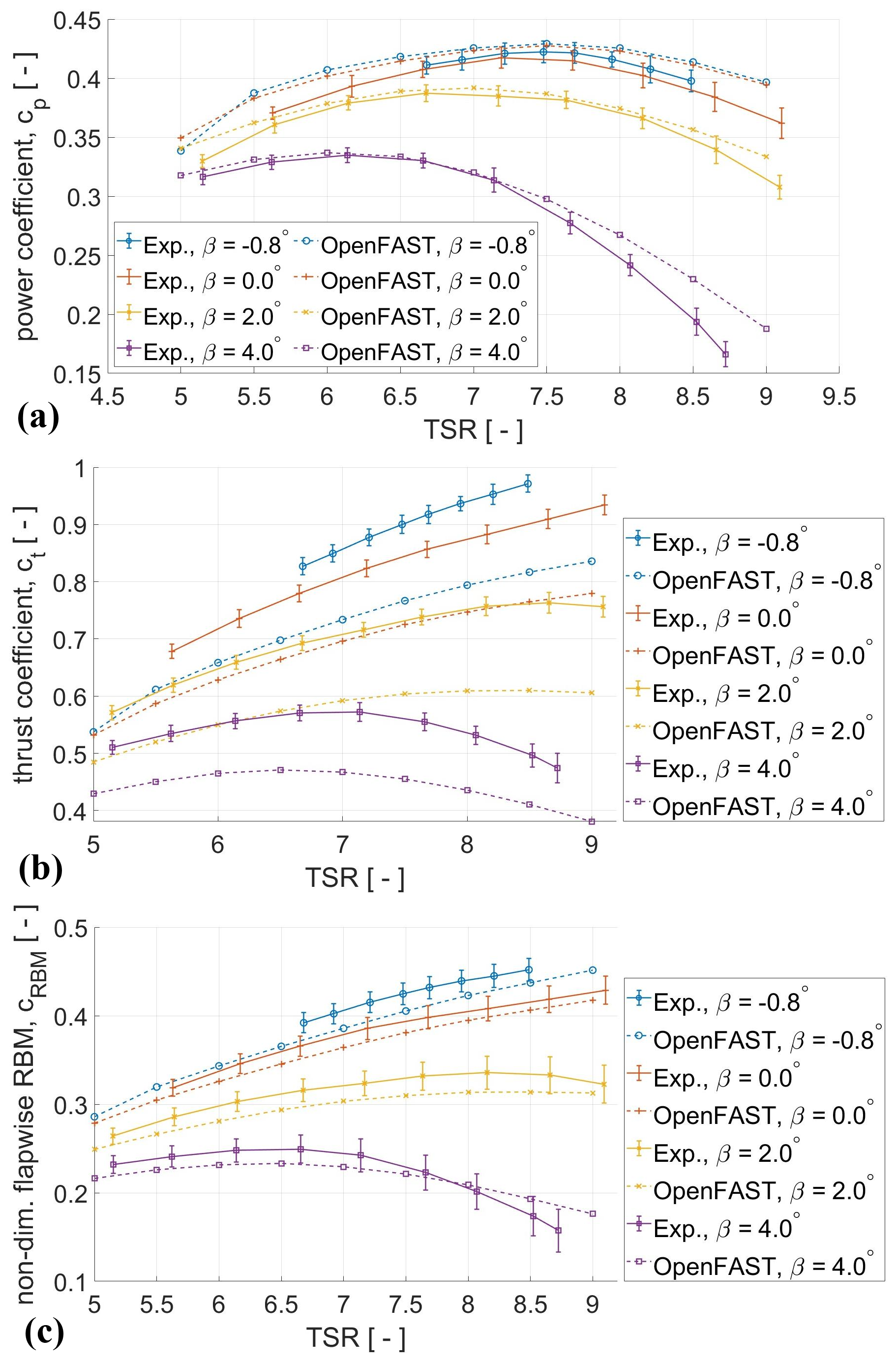
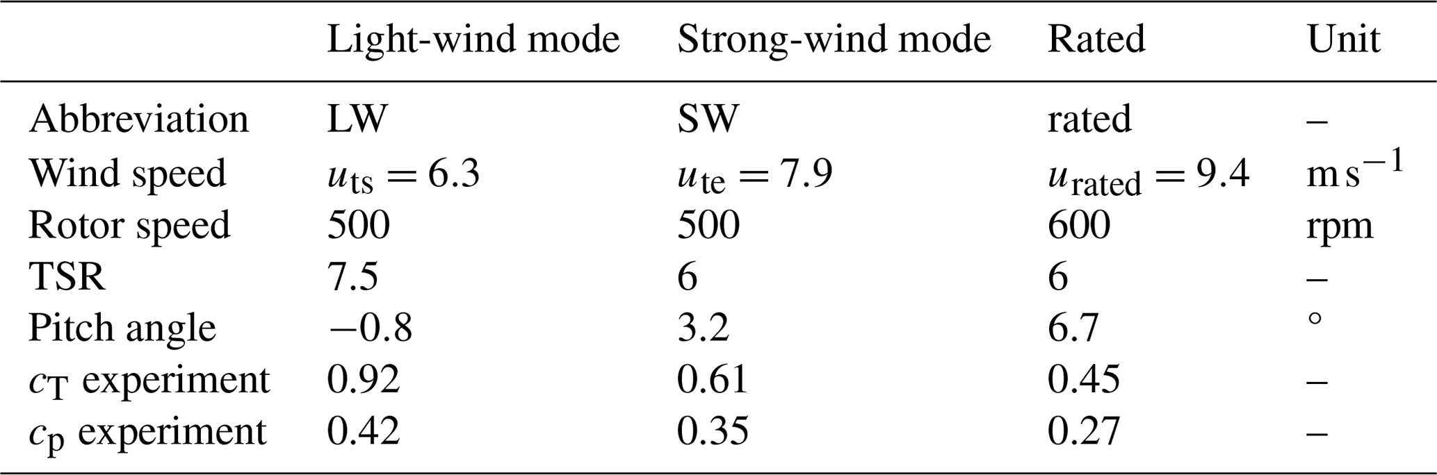
Figure 8Power coefficient (a), thrust coefficient (b), and non-dimensional flapwise RBM (c) from measurements and BEM simulations for various TSRs and pitch angles βpitch, at a constant rotor speed of 500 rpm.
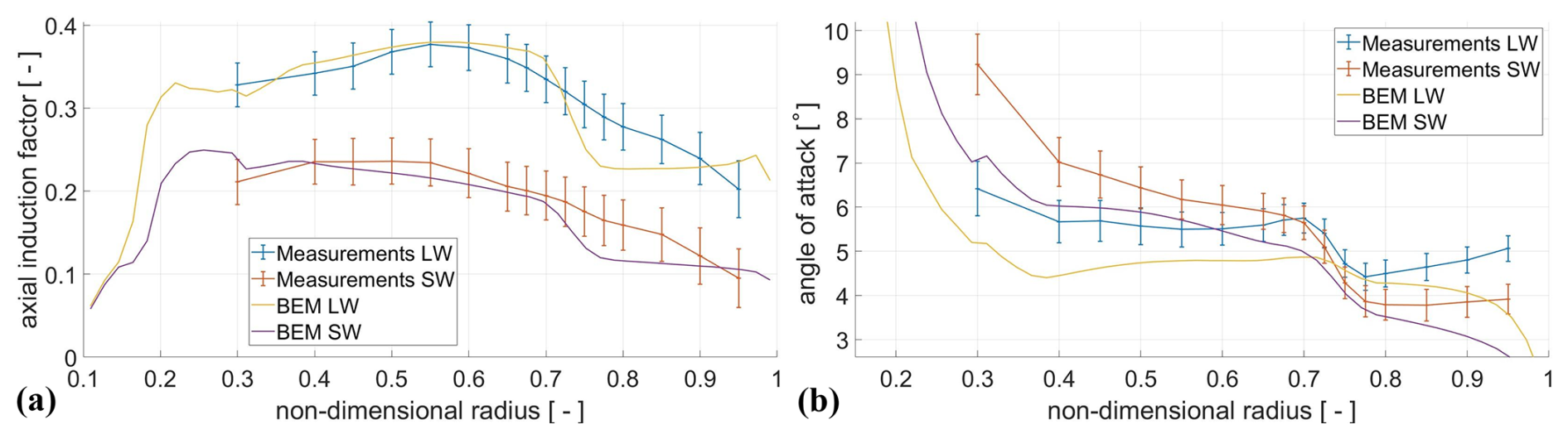
Figure 9Axial induction along the blade span (a) and angle of attack (b) from measurements and BEM simulations for the light-wind (LW) and strong-wind (SW) modes.
For additional investigations on the radial flow component in the rotor plane (Sect. 4.2) and the wake behaviour of the Hybrid-Lambda model rotor and the conventional model rotor (Sect. 4.4), FVW simulations are carried out with the OLAF module in OpenFAST v3.5, as described by Branlard et al. (2022) and Shaler et al. (2020). We aimed for a representation of an undisturbed wake, focusing on the effects that result from the aerodynamic blade design. Consequently, no tower shadow model is used, and the core spread eddy viscosity (viscous diffusion parameter) is set to 100 in order to allow for a free convection of the wake for a distance of multiple diameters downstream. Further, at the time of this study, no nacelle drag model was implemented in OLAF. For all simulations, the inflow is modelled as uniform over the rotor area and constant in time without added turbulence. Similar to the experiments, the comparison of the Hybrid-Lambda Rotor and the conventional rotor is carried out at the same thrust coefficient in the light-wind mode.
In this section the results from the wind tunnel experiments and the complementary simulations are presented. We first address rotor-integrated quantities in Sect. 4.1 and then expand to radially resolved measurements in Sect. 4.2. Next, we compare the dynamic response of the Hybrid-Lambda Rotor due to gusts with the response of the conventional rotor in Sect. 4.3. Finally, we characterize and compare the wake of the two model wind turbines in Sect. 4.4.
4.1 Rotor-integrated quantities
Characterizing the newly designed model rotor is an important step. The derived performance curves of the power coefficient, thrust coefficient, and flapwise RBM, resolved over a fine mesh of TSR and pitch, are used to validate the blade design and define operating points for further experiments. Such a characterization is further needed for controller implementations in future studies. In total, 91 combinations of TSRs and pitch angles were measured with a constant rotational speed of 500 rpm. For the sake of clarity, only a small portion of the results is plotted in Fig. 8. Overall, the measured power coefficient shows good agreement with the BEM simulations. The measurement values are lower than those from the simulations, which could indicate that the simulated airfoil polars overestimated the performance at the low Reynolds numbers. Both measurements and simulations show the highest power coefficient at similar operating points, i.e. TSR and pitch combinations. The difference in maximum cp between measurement and simulation data is about 2 %. Differences are larger for off-design operational points, such as the combinations of large pitch angles with very high or very low TSRs. The curves of the thrust coefficient show a similar shape over TSR and pitch angle compared to the simulations but with a considerable offset. Although correction models for the tower drag are applied, as explained in Sect. 3.3, an offset in the thrust coefficient of about 13 % is present for the operating point with maximal cp. The non-dimensional flapwise RBM is plotted in Fig. 8 and is defined in Eq. (14).
Here, is the dynamic pressure, R is the rotor radius used as a characteristic length, and is the rotor area divided by the number of blades. The measured flapwise RBMs (My) are in good agreement with the simulations. The relative difference between the measured RBMs and the simulations is 4 % in the operational point of maximum cp.
Figure 10Averaged radial velocity component (a) and envelope of the radial velocity component (b) in the rotor plane from FVW simulations for the two model turbines.
4.2 Radially resolved quantities
In this section, we address the measurements of the axial induction and angle of attack distribution over the blade span. We further investigate the radial velocity component in the rotor plane, as derived from FVW simulations, since this quantity was not measured within the measurement campaign. The measurements of the axial induction with the LDA show a fair match with the BEM simulations for the inner blade region () for both operating modes, as displayed in Fig. 9a. However, the steep gradients in the blending region of the blade design are not present in the LDA measurements. The measurements show a smeared-out and less steep gradient at . Since the flow in the rotor plane is three-dimensional, the assumption of independent blade elements in the BEM theory is invalid, and the gradients can not be captured by the BEM theory. The radial velocity components are further addressed in the next paragraph. The derived angle of attack distributions are plotted in Fig. 9b. The measurements show that the contrary tilting of the distribution works; i.e. when switching from the light-wind to the strong-wind mode, the angle of attack increases for the inner 70 % of the blade length and decreases for the outer 30 %, as expected. In close vicinity to the blade tip (), the modelling of the tip loss effect leads to deviations between the measurements and the BEM simulations. The two outermost measurement points should be treated with care since the tip loss effect influences the bisectrix method by Herráez et al. (2018). Overall, a minor offset of about 0.6° between the measurements and the simulations can be observed. However, the slopes of the angle of attack distribution match reasonably well, with the exception of the tip region.
Next, we explore possible reasons for the milder gradients in the axial induction distribution. In the BEM theory, the blade elements are treated independently of each other. This assumption is clearly violated with the blade design of the Hybrid-Lambda Rotor. To reveal further insights into the flow in the rotor plane, we use FVW simulations for the conventional and Hybrid-Lambda model turbines. The radial velocity component is extracted on a horizontal line in the rotor plane in a non-rotating coordinate system, and the average over all time steps is shown in Fig. 10. The time step used corresponds to an azimuthal resolution of 1.5°. Figure 10 shows the envelope, i.e. the minimum and maximum of the radial flow, thus displaying the impact of the passing blades and the associated vortices. A comparison of the two blade designs confirms an increased radial outboard flow component for the Hybrid-Lambda Rotor, almost over the entire rotor span. However, it is especially increased in the design blending region at 70 % blade length. The envelope shows lower extreme values at the blade tip for the Hybrid-Lambda Rotor. This is due to the increased axial wind speed component in the outer rotor annulus. Consequently, the difference in wind speed compared to the free stream is lower, and less radial flow is observed. The conventional rotor has a much higher axial induction near the blade tip (compare with Fig. 5a), which explains the larger magnitudes in the radial flow envelope. However, the envelope also reveals a second peak in the blending region of the Hybrid-Lambda Rotor, which means that the shear layer between the axial flow in the inner rotor disc and the outer annulus also introduces additional radial flow. This clearly highlights that the blade elements can not be treated independently, and complex, three-dimensional flow structures lead to the smearing of the steep gradients. Figure 10 also shows the differences in the radial flow between the operating modes. When the Hybrid-Lambda Rotor switches from the light-wind to the strong-wind mode, the radial velocity component decreases because the axial induction and the thrust coefficient are reduced, and there is less widening of the stream tubes. In contrast, the conventional rotor maintains the same operational point (same TSR and pitch angle) until rated wind speed, since no load limitation is applied. This means that the thrust coefficient and the axial induction remain constant. When the axial wind speed increases, the radial velocity component will also increase in the rotor area of the conventional turbine. Absolute velocity values are plotted in Fig. 10. The flow in the wake of the Hybrid-Lambda Rotor is further investigated in Sect. 4.4, and the influence of the trailing vortices is explained, which also heavily influence the flow in the rotor area.
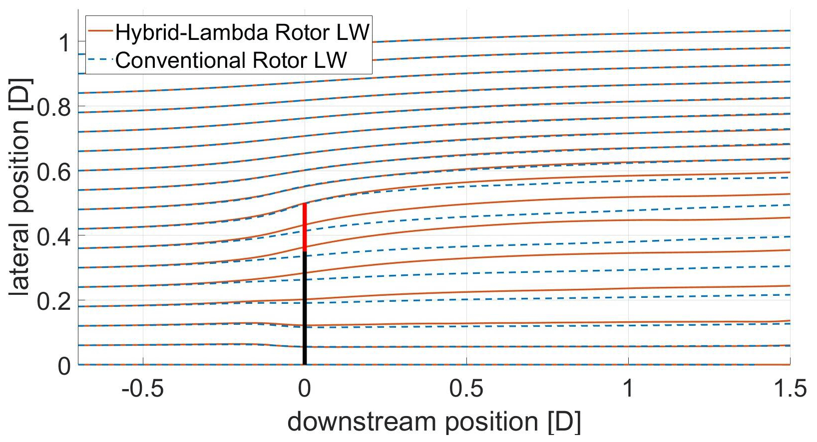
Figure 11Streamlines from FVW simulations for the Hybrid-Lambda model turbine in the LW mode and the conventional model turbine (same cT). The rotor is indicated with the vertical black bar, and the low-induction tips are displayed in bright red.
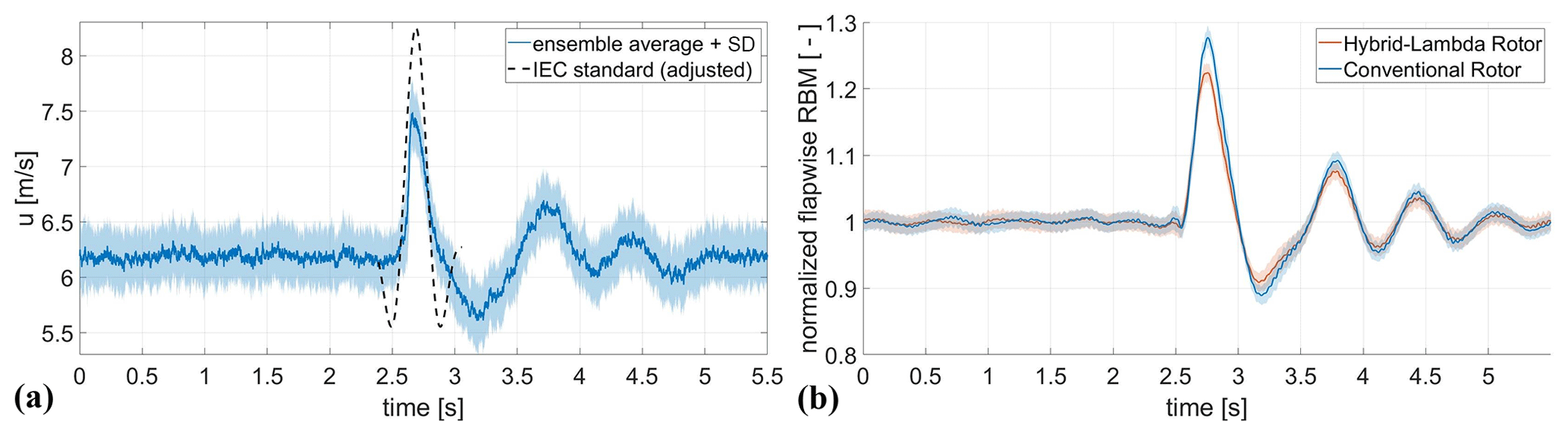
Figure 12Gust in the wind tunnel: inflow hot-wire measurements in the rotor plane and scaled IEC gust, displayed 8 times slower than ideal scaling; gust amplitude is not scaled (a). Flapwise RBM response of the Hybrid-Lambda Rotor and the conventional rotor. The shaded area indicates the 95 % confidence interval of the 45 repetitions of the gust event (b).
From the FVW simulations we can further extract the streamlines for both model turbines, which are shown in Fig. 11. The streamlines that pass along the tip of the rotors are almost identical between the two turbines. This means that the outer shape of the wake is similar. In contrast, the streamlines of the Hybrid-Lambda Rotor inside the wake are pushed further outwards compared to the conventional model turbine. Here, the effect of the increased radial flow is visible. If one considers the conservation of mass flow, the slower air in the inner part of the rotor has to expand into the outer wake annulus (compare with the wake investigations in Sect. 4.4). Thus, the streamlines in the outer part of the wake are closer together.
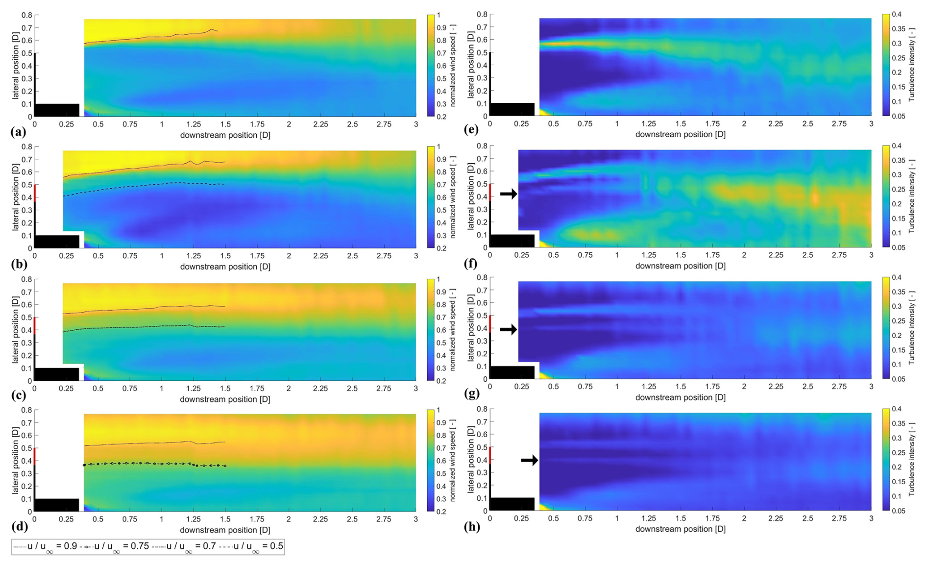
Figure 13Mean normalized wind speed (a–d) and turbulence intensity (e–h) from hot-wire measurements in the wake of the model turbines. From top to bottom: conventional rotor (a, e) and Hybrid-Lambda Rotor in the LW mode (b, f), in the SW mode (c, g), and at rated wind speed (d, h). Nacelle and blades are displayed in black, and the outer 30 % of the Hybrid-Lambda blades are displayed in red. The black arrows point at the second shear layer starting at the blade design blending region.
4.3 Dynamic response to gust events
We compared the response of the flapwise RBM to gust events between the two sets of blades. The gust events were generated with the active grid, mimicking a scaled extreme operating gust with the so-called Mexican hat shape, according to IEC 61400-1 (2019). The inflow was characterized by Neuhaus et al. (2021) with hot-wire measurements of multiple repetitions of the gust event in the centre of the rotor plane, which are plotted in Fig. 12. These active-grid settings were derived as the optimum trade-off between the frequency and the amplitude of the gust, as described in Sect. 3.1. The oscillations in the wind speed after the gust event (for t>3.2 s) are a pumping effect of the flow induced by the active grid, which can not be avoided for such fast changes in the wind speed. The ensemble-averaged response in the flapwise RBM for the two rotors is displayed in Fig. 12. Note that no wind turbine controller was applied in this study. The pitch angle remains constant, and the rotational speed is controlled to be constant over the entire gust event. The Hybrid-Lambda Rotor is in the light-wind operating mode during the steady inflow period before the gust event. The conventional rotor is operated at the same TSR of 7.5, and the pitch is set in order to match the same flapwise RBM between the two rotors in the steady inflow period. This allows us to compare the pure aerodynamic response of the rotors. The amplitude of the load overshoot is less for the Hybrid-Lambda Rotor, and the maximum flapwise RBM is 4.3 % higher for the conventional blades. The reduced axial induction in the outer part of the Hybrid-Lambda blades helps to mitigate the load overshoot. Similar conclusions were drawn by Ribnitzky et al. (2024) when comparing the effect of extreme-wind-shear events on the 15 MW Hybrid-Lambda Rotor and a reference rotor on a full-scale level with BEM simulations.
4.4 Wake characterization
In this section, we provide an in-depth analysis and comparison of the wake of the two rotors, using hot-wire measurements and FVW simulations. The hot-wire measurements are performed in the open-jet configuration of the wind tunnel, as explained in Sect. 3.1. This means that there is a shear layer between the wind tunnel jet and the still air around the nozzle. For large distances to the wind tunnel nozzle, there is an unavoidable interaction of the wind tunnel shear layer with the wake of the turbine. Measurement data for downstream distances larger than 2 D should be treated with care, especially for larger lateral distances to the centre line. Nevertheless, the data can provide an impression of the overall picture, and we consequently decided to plot the data up to 3 D downstream. Figure 13 shows the normalized wind speed and the turbulence intensity in the wake of the two rotors. A major advantage of the Hybrid-Lambda Rotor becomes clear when comparing the wake for the different operating modes. When the wind speed increases and the rotor shifts to the strong-wind mode and further to rated conditions, the pitch angle is increased, as shown in the control schedule in Fig. 4. Consequently, the thrust coefficient is reduced, the wake deficits are greatly decreased (see also Fig. 14), and the opening angle of the wake (e.g. the expansion of the stream tube) is reduced. This is of immense importance when evaluating the rotor concept in wind farm applications. In contrast, a conventional rotor would operate with the same axial induction and thrust coefficient until rated wind speed. Consequently, the wake deficits remain unchanged, and we only provide one plot for the conventional rotor. The second aspect that we discuss is the shape of the wake. The axial induction distribution of the Hybrid-Lambda Rotor is clearly mirrored in the wake profiles. The low-induction design of the outer 30 % of the blades leads to an outer annulus with reduced wake deficits, which is highlighted in Fig. 13 with the contour lines. In contrast, the inner part of the blade is designed for a higher axial induction compared to the conventional rotor (see Fig. 5a), thus resulting in lower wind speeds in the centre of the wake. Note that the axial induction is a free design variable in the Hybrid-Lambda design methodology, and the blade design could be adjusted when optimizing for the mitigation of wake effects, e.g. choosing a slightly lower axial induction for the inner blade section. However, the wind tunnel model of the Hybrid-Lambda Rotor was not designed to outperform the conventional model in terms of wake effects but with the objective of incorporating the wake characteristics of the full-scale Hybrid-Lambda model.
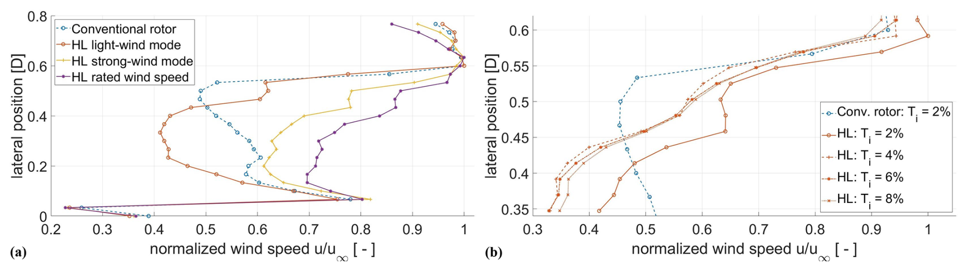
Figure 14Wake profiles at a distance of 0.4 D downstream for the two model rotors. At Ti=2 % for different operating modes (a) and in the light-wind mode for different Ti values (b).
The outer annulus with reduced wake deficits leads to a second shear layer at the border to the inner wake core with lower wind speeds. This is highlighted by the black arrows in Fig. 13, showing the local turbulence intensity, which is defined as . For now, we only address this as a shear layer, since the vorticity can not be derived from one-dimensional hot-wire measurements. We further look into the vorticity in the following paragraphs. The conventional rotor exhibits a single shear layer between the wake and the free stream, which leads to a single ring of increased turbulence intensity that widens up with further downstream distances. In contrast, for the Hybrid-Lambda Rotor, two rings of increased turbulence intensity can be observed. However, the magnitude of the turbulence intensity of both rings is lower compared to that of the single ring from the conventional rotor. The first ring emerges from the blade tip; the second one is shed at the blending region on the blade at 70 % blade length (if one considers the opening angle of the wake). Travelling downstream, these two shear layers widen up and start to interact with each other, which finally leads to a region of very high turbulence intensity for downstream distances larger than 2 D. This effect is most prominent in the light-wind mode. However, the two rings of increased turbulence intensity are still noticeable in the strong-wind mode and under rated conditions. Figure 13 further shows how the shape of these rings changes between the operating modes. While they are bent outwards in the light-wind mode, the curvature and opening angle decrease when switching to the strong-wind mode, and the rings are almost straight. Under rated conditions, they even tend to have a slight inwards-directed taper.
From previous FVW simulations and LESs on the full-scale Hybrid-Lambda Rotor, Ribnitzky et al. (2023) discovered that with increasing turbulence intensity in the inflow, the outer annulus with reduced wake deficits smears out. This means that the step-shaped wake profile, with a region of constant high wind speed in the outer annulus, develops more into a gradual change between the inner and outer wake deficits. This transition happens closer to the rotor for higher turbulence levels. To further investigate this, hot-wire measurements were performed 0.4 D behind the rotor with a hot-wire spacing of 4 cm (instead of 6 cm for all other cases presented before), with four different turbulence intensities in the inflow, generated with the active grid. The free-stream velocity among the different turbulence-levels was not exactly matched, since the activation of the active grid impacts the mean wind speed. Although the active-grid protocols were iterated in order to match the free-stream velocity as best as possible, small deviations of around 5 % to 10 % in the free-stream velocity remain. However, this does not affect the gradients of the wake profiles, which are the focus of interest in this case. The results are shown in Fig. 14, and the smearing of the outer wake annulus is clearly visible. Especially for the case with 8 % inflow turbulence intensity, the plateau with higher wind speeds vanishes.
We assume that the inner shear layer is also coupled to an additional vortex system that emerges from the blending region on the blade. Since the vorticity can not be derived from one-dimensional hot-wire measurements, we use FVW simulations to investigate this assumption. First, the FVW simulations confirm the characteristics of the wake of the Hybrid-Lambda Rotor. The mean wind speed, plotted in Fig. 15, also shows the outer annulus with higher wind speeds in both operating modes, as well as the reduced wake deficits and reduced wake expansion in the strong-wind mode. The vorticity is computed as the magnitude of the three vorticity components. The vorticity plots clearly highlight a second ring of vortices emerging from the blending region on the blade. The magnitude of the vorticity is lower than for the tip vortex, as also observed in the turbulence intensity derived from the hot-wire measurements. The FVW simulations are set up in a way to produce a wake that is as undisturbed as possible, e.g. using laminar and uniform inflow and a relatively low core spread eddy viscosity. This simulation set-up is chosen to identify a clear representation of the vortex rings and their positions. Consequently, the vortex systems do not break up noticeably, and the interaction between the inner and outer rings of vortices is rather low.
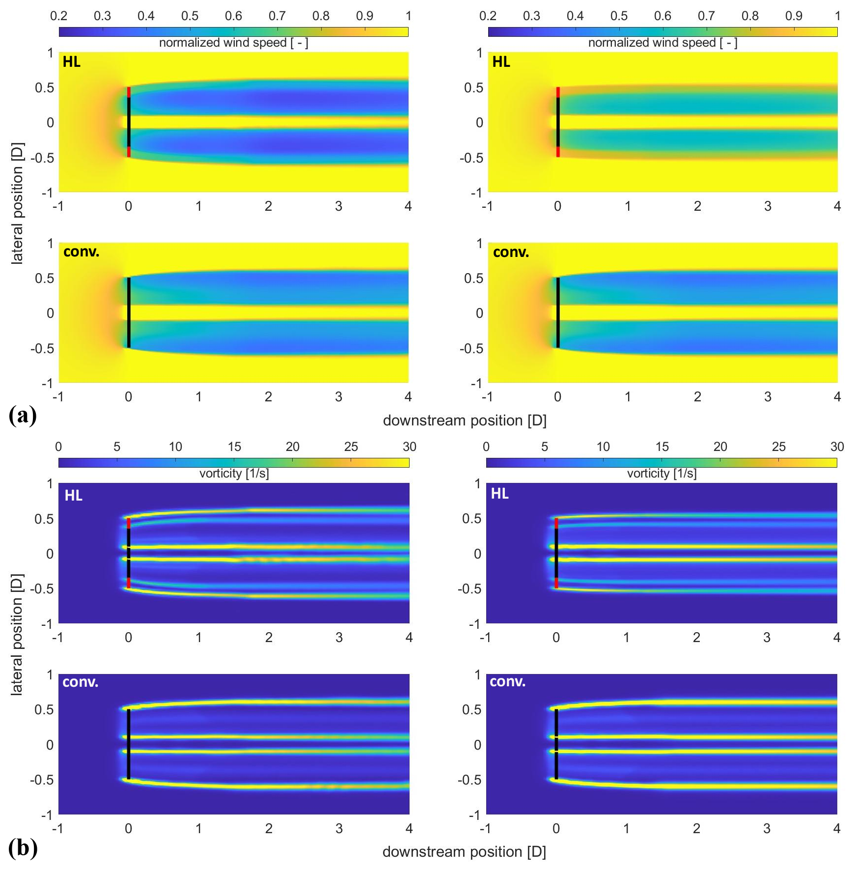
Figure 15Normalized wind speed (a) in the light-wind (left) and strong-wind modes (right). Vorticity magnitude (b) in the light-wind (left) and strong-wind modes (right) for the Hybrid-Lambda model turbine (top) and the conventional model turbine (bottom) from FVW simulations.
All in all, the measurement results are in very good agreement with the FVW simulations and LESs that were carried out by Ribnitzky et al. (2023) on the 15 MW full-scale Hybrid-Lambda Rotor, where an improved wake recovery was also observed. In short, the results indicate three major advantages of the Hybrid-Lambda Rotor in wind farm applications: first, the decreased wake deficits for a large range of wind speeds below rated (for ); the increased wind speeds in the outer wake annulus, which are beneficial for partial-wake scenarios; and the enhanced wake mixing due to the additional shear layer and vortex system in the wake.
Scaling wind turbine rotors to wind tunnel size is a delicate scientific task since not all physical characteristics can be matched exactly. The scaling objectives need to be defined precisely, and compromises need to be made regarding the matching of classical aerodynamic non-dimensional parameters. In this paper, we developed a method on how to scale the Hybrid-Lambda Rotor to wind tunnel size with objectives that differ from those of other aerodynamic scaling approaches found in the literature, as described by Canet et al. (2021), Bottasso and Campagnolo (2021), and Gasch and Twele (2012), among others. The concept involves a blade design for two TSRs, which is a challenge on its own. But additionally, we need to transfer the design method to lower TSRs in order to derive large enough chord lengths and Reynolds numbers. This leads to a novel scaling approach, coupled with the objective of matching the non-uniform distribution of axial induction along the blade span for two different operating modes.
This scaling approach fulfilled its aim of replicating the aerodynamic characteristics at wind tunnel scale by means of an aerodynamic redesign with low-Reynolds-number profiles. For the sake of comparability with the reference model turbine, as described in Berger et al. (2018), we chose the same airfoils: SG6040 and SG6041. Although we decided otherwise, we want to draw the attention of future designers of model wind turbines to the low-Reynolds-number airfoil SD7032, which was experimentally investigated by Fontanella et al. (2021), and for which a high-quality data set for the airfoil polars under various Reynolds numbers is available.
The investigation of the scaled rotor in the wind tunnel shows that the switching between the operating modes and the associated tilting of the spanwise angle of attack distribution work similarly to the full-scale rotor, which fulfils one of the major scaling objectives. In the measurements, the spanwise change in the axial induction distribution is smeared out, which can not be reproduced by the model assumptions inherent in the BEM simulations. Complex flow structures were identified as an increased radial flow in the rotor plane and an additional vortex system that is shed from the blending region on the blade. Here, the question arises as to how the scaling affects the rotational augmentation and the radial flow components in the rotor plane, since the Rossby number (ratio of inertia to Coriolis forces) is not matched in the given scaling approach. Further, the local blade solidity is increased for the model turbine, which can further enhance the effect of rotational augmentation compared to the full-scale rotor (Herráez et al., 2016). However, FVW simulations for the full-scale turbines do confirm that the radial flow component is increased for the Hybrid-Lambda turbine compared to the reference turbine in a similar manner to that shown in this paper for the model turbine. Further, the additional vortex system is also found in the full-scale simulations. Full insights into the complex flow phenomena on the blade and the impact of the scaling approach could only be revealed by blade-resolved CFD simulations, which is out of the scope of this study.
Furthermore, the wind tunnel model allowed us to reveal the unique wake characteristics of the Hybrid-Lambda Rotor and underline three major advantages in the wake behaviour: first, the decreased wake deficits in the strong-wind mode; second, the increased wind speed in the outer wake annulus in the entire partial load range; and third, the additional shear layer and vortex system. To the best of the authors' knowledge, such a blade design with radially variable axial induction has never been investigated in a wind tunnel before, which includes the ability to change the operating mode by changing the operational TSR, tilting the spanwise angle of attack distribution, and reducing the axial induction. The major findings in this paper emphasize that the Hybrid-Lambda design methodology works reasonably well, but when designing a blade with such strong gradients along the blade span, one can not rely solely on the BEM theory. This was somewhat expected, since the first version of the Hybrid-Lambda Rotor was designed to separate the effects on the inner and outer parts of the blade and to push the limits of the applicability of the BEM theory, where the blade elements are treated independently.
These findings are in line with previous FVW and LES investigations on the full-scale Hybrid-Lambda Rotor by Ribnitzky et al. (2023). A smearing of the gradients in the axial induction distribution was also recognized in the FVW investigations. Further, the difference in the axial induction between the inner and outer parts of the blade was found to be reduced compared to that in the BEM simulations. Finally, the wake characteristics show very good agreement between the measurements presented in this paper and the aforementioned FVW simulations and LESs on the full-scale rotor. The outer wake annulus behaves very similarly across the simulations and the measurements, considering the wind speed distribution and turbulence intensities. It was further found with both methods that the gradients in the wake profile smear out with increasing turbulence intensity. Paulsen et al. (2024) investigated the Hybrid-Lambda Rotor using mesoscale weather research models. They showed that the benefits of using a wind farm application even outweigh those of using a single turbine due to the reduced wake losses.
When we compare the hot-wire measurements in the wake with the LDA measurements in the rotor plane, we discover some discrepancies. The gradients in the axial induction seem to be smeared out when considering the LDA data. However, the wake profiles recorded with the hot wires reveal a relatively steep gradient in the velocity profiles. This leads us to the limitations of the applied method, which aims to derive the axial induction in the rotor plane by probing the wind speed in the bisectrix of two blades. According to Herráez et al. (2018), ideally, the induction of the rotor blades is counterbalanced, and the velocities extracted from the rotor plane are only influenced by the wake induction and not by the blade induction itself. However, this method can not capture the influence of the local trailed and shed vorticities accurately. This usually applies to the tip region (), where the tip vortex starts to dominate the flow. In the present study, we found a second vortex system that emerges from the blending region on the blade and that will influence the circulation distribution along the blade span. Consequently, the LDA measurements close to the design blending region are also influenced by the additional vortex, and those results should be treated with care. Since the vortex emerges from the blade, the LDA does not record steep gradients in the rotor plane. Only with some downstream distance does the vortex lead to sharp velocity gradients, which can be captured with the hot wires in the wake. Considering the outwards bending of the streamlines in Fig. 11, we can conclude that the inner wake core with the slower flow expands and pushes into the outer wake annulus. Consequently, the steep gradients in the wake profiles seem to develop within the first 0.5 D downstream of the rotor. This can somehow link the low gradients from the LDA measurements in the rotor plane to the steep gradients from the hot-wire data in the wake. Nevertheless, more measurements in direct proximity to the rotor with both measurement techniques would be necessary to support this hypothesis. Despite the methodological limitations, the overall results and the combination of the hot-wire measurements in the wake with the FVW simulations give a good representation of the bigger picture concerning the flow structures in the wake of the Hybrid-Lambda Rotor.
In this paper, we first developed a method to scale the Hybrid-Lambda Rotor to wind tunnel size. Second, we investigated the influence of the steep gradients of axial induction along the blade span on the rotor aerodynamics. Third, we thoroughly analysed the wake characteristics of the Hybrid-Lambda Rotor and compared them to those of a conventional model rotor. We showed that it is possible to transfer a complex rotor concept to wind tunnel size and to lower design TSRs. In this delicate process of finding a compromise, it is necessary to precisely define the scaling objectives. In this case we aimed to match the axial induction distribution and reproduce the shift in the angle of attack distribution when switching between the operating modes.
With the experimental investigations in the wind tunnel, we analysed the impact of the steep spanwise gradients in the blade design, which lead to a complex three-dimensional flow. We found an additional shear layer and vortex system in the wake of the Hybrid-Lambda Rotor, and we quantified the reduced wake deficits in the strong-wind mode and under rated conditions. Further, we tested the Hybrid-Lambda Rotor in gust events, and the results show that the low-induction design of the outer part of the blade is beneficial and reduces the load overshoot by more than 4 % compared to the conventional model turbine. The derived results improve our understanding of the three-dimensional flow patterns that are introduced by the Hybrid-Lambda Rotor concept and provide a valuable complementary data set to the simulations on the full-scale rotor, as described by Ribnitzky et al. (2024). Further, the developed methodology can offer new inspirations when solving other scaling problems for complex wind turbine systems.
In this paper, we focused on aerodynamic effects and steady-state operation. In a full-scale application, reliable and safe operation of offshore low-specific-rating turbines with such large rotors can only be achieved with sophisticated control strategies. Specifically for the Hybrid-Lambda Rotor, the controller development should aim to realize the transient change in operating modes and apply techniques that limit extreme loads. The scaled model presented here offers the opportunity to test different controller versions under various reproducible turbulent inflow conditions in the wind tunnel, which will be addressed in future studies.
The successful experimental validation of the aerodynamic concept of the Hybrid-Lambda Rotor, so far on wind tunnel scale, confirms the potential of deploying low-specific-rating turbines at offshore sites. This can favour a higher and less fluctuating power feed-in at low to medium wind speeds, thus contributing to the transition toward a reliable and economically viable wind energy supply. Load-limiting strategies are necessary to enable rotors with such large diameters, and the accompanying losses in efficiency must be carefully considered within the design process. The Hybrid-Lambda Rotor can offer a possible solution, and with the experimental work presented here, we have taken the next step in validating the concept.
For the Hybrid-Lambda model turbine, we provide the blade geometry as a CAD file and the turbine simulation model for OpenFAST. We further provide the mean wind speeds and turbulence intensities from the hot-wire measurements in the wake, as shown in Fig. 13, under the following repository: https://doi.org/10.5281/zenodo.14883915 (Ribnitzky, 2025).
DR developed the scaling methodology, designed the Hybrid-Lambda model turbine blades, conducted the experiments and simulations, post-processed the data, and wrote the paper; VP supervised the experiments and the post-processing; and MK contributed with effective discussions to the scaling methodology and to the blade design and supervised the investigations. All co-authors thoroughly reviewed the paper.
The contact author has declared that none of the authors has any competing interests.
Publisher's note: Copernicus Publications remains neutral with regard to jurisdictional claims made in the text, published maps, institutional affiliations, or any other geographical representation in this paper. While Copernicus Publications makes every effort to include appropriate place names, the final responsibility lies with the authors.
We would like to thank Lars Neuhaus and Tom Wester for the support during the measurements.
The work presented in this paper was funded by the Deutsche Forschungsgemeinschaft (DFG, German Research Foundation) – project ID 434502799 – SFB 1463.
This paper was edited by Alessandro Croce and reviewed by two anonymous referees.
Bayati, I., Belloli, M., Bernini, L., Mikkelsen, R., and Zasso, A.: On the aero-elastic design of the DTU 10 MW wind turbine blade for the LIFES50+ wind tunnel scale model, J. Phys. Conf. Ser., 753, 022028, https://doi.org/10.1088/1742-6596/753/2/022028, 2016. a
Berger, F.: Wind tunnel experiments with a model turbine: Dynamic inflow investigation, Dissertation, https://oops.uni-oldenburg.de/id/eprint/5516 (last access: 1 July 2025), 2022. a, b
Berger, F., Kröger, L., Onnen, D., Petrović, V., and Kühn, M.: Scaled wind turbine setup in a turbulent wind tunnel, J. Phys. Conf. Ser., 1104, 012026, https://doi.org/10.1088/1742-6596/1104/1/012026, 2018. a, b, c
Berger, F., Onnen, D., Schepers, G., and Kühn, M.: Experimental analysis of radially resolved dynamic inflow effects due to pitch steps, Wind Energ. Sci., 6, 1341–1361, https://doi.org/10.5194/wes-6-1341-2021, 2021. a, b
Bottasso, C. L. and Campagnolo, F.: Wind Tunnel Testing of Wind Turbines and Farms, in: Handbook of Wind Energy Aerodynamics, edited by: Stoevesandt, B., Schepers, G., Fuglsang, P., and Yuping, S., Springer, https://doi.org/10.1007/978-3-030-05455-7_54-1, 2021. a, b, c
Bottasso, C. L., Campagnolo, F., and Petrović, V.: Wind tunnel testing of scaled wind turbine models: Beyond aerodynamics, J. Wind Eng. Ind. Aerod., 127, 11–28, https://doi.org/10.1016/j.jweia.2014.01.009, 2014. a
Branlard, E., Brownstein, I., Strom, B., Jonkman, J., Dana, S., and Baring-Gould, E. I.: A multipurpose lifting-line flow solver for arbitrary wind energy concepts, Wind Energ. Sci., 7, 455–467, https://doi.org/10.5194/wes-7-455-2022, 2022. a
Buhl, L.: A New Empirical Relationship between Thrust Coefficient and Induction Factor for the Turbulent Windmill State, National Renewable Energy Laboratory, NREL/TP-500-36834, https://doi.org/10.2172/15016819, 2005. a
Campagnolo, F., Petrović, V., Schreiber, J., Nanos, E. M., Croce, A., and Bottasso, C. L.: Wind tunnel testing of a closed-loop wake deflection controller for wind farm power maximization, J. Phys. Conf. Ser., 753, 032006, https://doi.org/10.1088/1742-6596/753/3/032006, 2016. a
Canet, H., Bortolotti, P., and Bottasso, C. L.: On the scaling of wind turbine rotors, Wind Energ. Sci., 6, 601–626, https://doi.org/10.5194/wes-6-601-2021, 2021. a, b
Dong, G., Qin, J., Li, Z., and Yang, X.: Characteristics of wind turbine wakes for different blade designs, J. Fluid Mech., 965, A15-1–A15-36, https://doi.org/10.1017/jfm.2023.385, 2023. a
Dörenkämper, M., Meyer, T., Baumgärtner, D., Borowski, J., Deters, C., Dietrich, E., Fricke, J., Hans, F., Jersch, T., Leimeister, M., Neshati, M. M., Pangalos, G., Quiroz López, T. E., Quistorf, G., Requate, N., Schalk, K. V., Schmidt, J., Schnackenberg, M., Schwegmann, S., Thomas, P., Vollmer, L., Walgern, J., Widerspan, V., and Zotieieva, H.: Weiterentwicklung der Rahmenbedingungen zur Planung von Windenergieanlagen auf See und Netzanbindungssystemen, Fraunhofer-Institut für Windenergiesysteme, https://doi.org/10.24406/publica-2202, 2023. a
Fontanella, A., Bayati, I., Mikkelsen, R., Belloli, M., and Zasso, A.: UNAFLOW: a holistic wind tunnel experiment about the aerodynamic response of floating wind turbines under imposed surge motion, Wind Energ. Sci., 6, 1169–1190, https://doi.org/10.5194/wes-6-1169-2021, 2021. a
Gasch, R. and Twele, J.: Wind Power Plants: Fundamentals, Design, Construction and Operation, 2nd edn., Springer, Berlin, https://doi.org/10.1007/978-3-642-22938-1, 2012. a, b, c
Giguere, P. and Selig, M. S.: New Airfoils for Small Horizontal Axis Wind Turbines, ASME Journal of Solar Energy Engineering, 120, 108–114, 1998. a
Hand, M. M., Simms, D. A., Fingersh, L. J., Jager, D. W., Cotrell, J. R., Schreck, S., and Larwood, S. M.: Unsteady Aerodynamics Experiment Phase VI: Wind Tunnel Test Configurations and Available Data Campaigns, National Renewable Energy Laboratory NREL/TP-500-29955, https://doi.org/10.2172/15000240, 2001. a
Hansen, M.: Aerodynamics of wind turbines, 2nd edn., Earthscan, London, ISBN 978-1-84407-438-9, 2008. a
Herráez, I., Akay, B., van Bussel, G. J. W., Peinke, J., and Stoevesandt, B.: Detailed analysis of the blade root flow of a horizontal axis wind turbine, Wind Energ. Sci., 1, 89–100, https://doi.org/10.5194/wes-1-89-2016, 2016. a
Herráez, I., Daniele, E., and Schepers, J. G.: Extraction of the wake induction and angle of attack on rotating wind turbine blades from PIV and CFD results, Wind Energ. Sci., 3, 1–9, https://doi.org/10.5194/wes-3-1-2018, 2018. a, b, c, d
Hulskamp, A. W., van Wingerden, J. W., Barlas, T., Champliaud, H., van Kuik, G. A. M., Bersee, H. E. N., and Verhaegen, M.: Design of a scaled wind turbine with a smart rotor for dynamic load control experiments, Wind Energy, 14, 339–354, https://doi.org/10.1002/we.424, 2011. a
IEC 61400-1: Wind energy generation systems – Part 1: Design requirements, International Electrotechnical Commission, ed. 4, 2019. a, b
Jonkman, B., Mudafort, R., Platt, A., Branlard, E., Sprague, M., Vijayakumar, G., Buhl, M., Ross, H., Bortolotti, P., Masciola, M., Ananthan, D., Schmidt, M., Rood, J., Hall, M., Bendl, K., and Martinez, T.: OpenFAST release v3.1.0, Zenodo [code], https://doi.org/10.5281/zenodo.6324288, 2022. a, b
Jonkman, J., Butterfield, S., Musial, W., and Scott, G.: Definition of a 5 MW Reference Wind Turbine for Offshore System Development, National Renewable Energy Laboratory, NREL/TP-500-38060, https://doi.org/10.2172/947422, 2009. a
Kelley, C., Maniaci, D., and Resor, B.: Horizontal-Axis Wind Turbine Wake Sensitivity to Different Blade Load Distributions, AIAA SciTech, SAND2014-20587C, https://doi.org/10.2514/6.2015-0490, 2014. a
Knauer, A.: Rotor blade shaped to enhance wake diffusion, European patent, EP 3 308 014 B1, 2021. a
Kröger, L., Frederik, J., van Wingerden, J.-W., Peinke, J., and Hölling, M.: Generation of user defined turbulent inflow conditions by an active grid for validation experiments, J. Phys. Conf. Ser., 1037, 052002, https://doi.org/10.1088/1742-6596/1037/5/052002, 2018. a
Krogstad, P. Å. and Lund, J. A.: An experimental and numerical study of the performance of a model turbine, Wind Energy, 15, 443–457, https://doi.org/10.1002/we.482, 2012. a
López Prol, J., Steininger, K. W., and Zilberman, D.: The cannibalization effect of wind and solar in the California wholesale electricity market, Energ. Econ., 85, 104552, https://doi.org/10.1016/j.eneco.2019.104552, 2020. a
Madsen, H. A., Zahle, F., Meng, F., Barlas, T., Rasmussen, F., and Rudolf, R. T.: Initial performance and load analysis of the LowWind turbine in comparison with a conventional turbine, J. Phys. Conf. Ser., 1618, 032011, https://doi.org/10.1088/1742-6596/1618/3/032011, 2020. a
May, N., Heuhoff, K., and Borggrefe, F.: Market incentives for system-friendly designs of wind turbines, DIW Economic Bulletin No. 24/2015, 313–321, 2015. a
Neuhaus, L., Berger, F., Peinke, J., and Hölling, M.: Exploring the capabilities of active grids, Exp. Fluids, 62, 130, https://doi.org/10.1007/s00348-021-03224-5, 2021. a, b, c, d
Paulsen, J., Dörenkämper, M., and Steinfeld, G.: Power production and large-scale wake effects of offshore wind turbines with low specific rating, J. Phys. Conf. Ser., 2767, 092060, https://doi.org/10.1088/1742-6596/2767/9/092060, 2024. a
Ribnitzky, D.: Hybrid-Lambda model turbine – blade geometry, openFAST model and wake measurement data, Zenodo [data set], https://doi.org/10.5281/zenodo.14883915, 2025. a
Ribnitzky, D., Berger, F., and Kühn, M.: Innovative aerodynamic rotor concept for demand-oriented power feed-in of offshore wind turbines, J. Phys. Conf. Ser., 2265, 032017, https://doi.org/10.1088/1742-6596/2265/3/032017, 2022. a
Ribnitzky, D., Bortolotti, P., Branlard, E., and Kühn, M.: Rotor and wake aerodynamic analysis of the Hybrid-Lambda concept – an offshore low-specific-rating rotor concept, J. Phys. Conf. Ser., 2626, 012008, https://doi.org/10.1088/1742-6596/2626/1/012008, 2023. a, b, c, d
Ribnitzky, D., Berger, F., Petrović, V., and Kühn, M.: Hybrid-Lambda: a low-specific-rating rotor concept for offshore wind turbines, Wind Energ. Sci., 9, 359–383, https://doi.org/10.5194/wes-9-359-2024, 2024. a, b, c, d, e, f, g
Schepers, J. P. and Snel, H.: Model Experiments in Controlled Conditions – Final Report, Tech. rep., ECN-E-07-042, Energy research Center of the Netherlands (ECN), Petten, https://publications.tno.nl/publication/34628817/8d6E4g/e07042.pdf (last access: 1 July 2025), 2008. a
Schneemann, J., Rott, A., Dörenkämper, M., Steinfeld, G., and Kühn, M.: Cluster wakes impact on a far-distant offshore wind farm's power, Wind Energ. Sci., 5, 29–49, https://doi.org/10.5194/wes-5-29-2020, 2020. a
Schottler, J., Hölling, A., Peinke, J., and Hölling, M.: Design and implementation of a controllable model wind turbine for experimental studies, J. Phys. Conf. Ser., 753, 072030, https://doi.org/10.1088/1742-6596/753/7/072030, 2016. a
Shaler, K., Branlard, E., and Platt, A.: OLAF User's Guide and Theory Manual, National Renewable Energy Laboratory, NREL/TP-5000-75959, https://doi.org/10.2172/1659853, 2020. a
Soto-Valle, R., Bartholomay, S., Alber, J., Manolesos, M., Nayeri, C. N., and Paschereit, C. O.: Determination of the angle of attack on a research wind turbine rotor blade using surface pressure measurements, Wind Energ. Sci., 5, 1771–1792, https://doi.org/10.5194/wes-5-1771-2020, 2020. a
Swisher, P., Murcia Leon, J. P., Gea-Bermúdez, J., Koivisto, M., Madsen, H. A., and Münster, M.: Competitiveness of a low specific power, low cut-out wind speed wind turbine in North and Central Europe towards 2050, Appl. Energ., 306, 118043, https://doi.org/10.1016/j.apenergy.2021.118043, 2022. a
Wang, C., Campagnolo, F., Canet, H., Barreiro, D. J., and Bottasso, C. L.: How realistic are the wakes of scaled wind turbine models?, Wind Energ. Sci., 6, 961–981, https://doi.org/10.5194/wes-6-961-2021, 2021. a
Yang, X., Boomsma, A., Sotiropoulos, F., Resor, B., Maniaci, D., and Kelley, C.: Effects of spanwise blade load distribution on wind turbine wake evolution, AIAA SciTech, 2015-0492, https://doi.org/10.2514/6.2015-0492, 2015. a