the Creative Commons Attribution 4.0 License.
the Creative Commons Attribution 4.0 License.
 | 15 May 2025
Control strategies for multi-rotor wind turbines
Finn Matras
Morten Dinhoff Pedersen
This work considers steady-state aspects of multi-rotor wind turbine control. In contrast to most literature on the topic, the underlying multi-rotor model includes the aerodynamic interactions between rotors. The model predicts that these interactions are central for effective control of multi-rotor wind turbines under some conditions. A numerical optimization problem is formulated to find the optimal control solutions, and two adaptations of the maximum power point tracking (MPPT) algorithm for the multi-rotor case are suggested. By employing furling for multi-rotor wind turbines, it is also shown that one can drastically reduce the bending moment of the structure. Other physical effects, such as operation with wind shear and simple failure handling, are also presented using a 23-rotor fixed-pitch multi-rotor wind turbine with a total rated power of 5 MW. The results are meant to be an enabling work, showcasing the possibilities and challenges involved in multi-rotor stability analysis and control problems.
- Article
(9041 KB) - Full-text XML
- BibTeX
- EndNote


This work is a compilation of the relevant work on multi-rotor wind turbines presented in the thesis of the main author (Matras, 2025).
Multi-rotor wind turbines have been a known concept for several centuries, but they have almost been disregarded when compared to their single-rotor counterparts. In the quest for cost reduction, single-rotor wind turbines have become bigger and bigger. While there might be many reasons for this trend, scaling laws dictate structural and aerodynamic challenges due to increasing rotor sizes. A natural alternative to increasing the rotor radius is to increase the rotor count and possibly to work with, rather than against, scaling laws by reducing the rotor radius. The idea has been investigated by reputable industry companies such as Vestas (van der Laan et al., 2019) and recent startups such as Wind Catching Systems AS (2021) and Myriad Wind Energy Systems (2024).
The multi-rotor concept with smaller rotor radii has many advantages, mainly rooted in the fact that it can be considered to discretize the continuous wind field in smaller areas, allowing it to more efficiently utilize the spatially varying wind field. Authors such as Jamieson (2011), Jamieson and Branney (2014), and Sandhu (2018) have investigated and discussed other aspects of rotor scaling and multi-rotor setups.
Successful application of multi-rotor wind turbines requires a thorough understanding of the system behavior and how they are best controlled for maximal power generation, load reduction and stability. The available literature on the topic is somewhat sparse, which is highlighted by the control challenge proposed in Sørensen et al. (2018), motivating researchers to contribute to the topic. Spagnolo et al. (2020) responded to the challenge and developed an extremum-seeking controller. Other aspects, such as yawing of a two-rotor wind turbine with variable pitch and optimal differential thrusting, was investigated by Guenoune et al. (2016) and MacMahon and Leithead (2018), respectively. Unfortunately, none of these contributions include the aerodynamic interactions between the rotors, which are believed to be significant based on their significance for multi-rotor helicopters (Johnson, 1994). Additionally, a multi-rotor setup with many smaller rotors will be able to better adapt to the local flow conditions than an equivalently big single-rotor system. Thus, a multi-rotor system can sample the wind field with greater fidelity than a single-rotor system. This sampling gives rise to further interactions that are assumed to be of importance. The present work includes a simplified model of the interactions, allowing for an investigation of how they affect the control and stability of a multi-rotor wind turbine at steady state in various operating regimes. The knowledge obtained from the analysis can be used to guide future attention to areas that are of significance for multi-rotor systems.
Modeling and control of single-rotor wind turbines are relatively well described in the literature; see Manwell et al. (2010), Apata and Oyedokun (2020), and Barzegar-Kalashani et al. (2023). The majority of large single-rotor wind turbines have blades with variable pitch, which adds modeling, design and control complexity and increases the number of failure points. Another advantage of multi-rotor wind turbines with smaller rotors is their increased rigidity, which can allow for control techniques using stalling or furling to effectively achieve a similar level of power control to a variable-pitch turbine. Furling for a multi-rotor wind turbine can be achieved by rotating the whole support structure to produce a yaw offset, as indicated by ψ in Fig. 1. This technique is used to illustrate an intriguing operation scheme for when the multi-rotor wind turbine needs to limit its power output.

Figure 1Illustration of turbine configuration. The x, y and z coordinates; ambient wind speed W(y) and direction ψ; thrusts F; and torques M.
As established in Matras and Pedersen (2024), the dynamics of multi-rotor systems are influenced by both the rotor count and the size of each individual rotor. This complicates any general study on the topic by making results case dependent, but it can be omitted by discussing the overall system behavior at steady state, which is what is done in this work.
From a control perspective, one can identify two main modes of operation at steady state: unconstrained and constrained operation. The former case considers the phase in which the main goal of a wind turbine is to maximize its energy production. This is typically achieved by using the well-known maximum power point tracking (MPPT) controller that dictates a generator torque proportional to the rotational velocity squared, as discussed in Johnson et al. (2006). While this has proven to work well for single-rotor turbines, its efficacy for the multi-rotor case remains to be proven. To this end, the results from applying the MPPT algorithm to each individual turbine are compared to the numerically optimal solution.
The second mode of operation, the constrained mode, can be trickier to handle due to the system complexity and the varying nature of the constraints. Algorithmically, this complicates the design because the MPPT algorithm is no longer viable, and other controllers need to be developed. The present work considers the numerically optimal solution, even though this can be too complex for real-time control. An advantage of the numerical optimal solution is that the solutions can be computed relatively easily for any desired constraints, of which the individual power constraint, a net bending moment constraint and yaw moment constraints are considered here to highlight some interesting properties of multi-rotor systems.
The findings from the two modes of operation are then used to inform a novel control strategy for multi-rotor wind turbines that, following the definition of Skogestad and Postlethwaite (2005), are self-optimizing and thus operate close to the numerically optimal solution using inherent system properties. It is worth noting that this analysis only considers steady-state behavior, and substantial engineering efforts still need to be made to get a proficient dynamic control system.
The foundation of the analysis is a simple steady-state multi-rotor model presented in Matras et al. (2024) based on the actuator disk concept. The main novelty of this model comes from the inclusion of the aerodynamic interactions between the rotors. Wind shear is also included as an extension of the model presented in Matras et al. (2024), and the required model parameters are adjusted to fit a 23-rotor wind turbine, as shown in Fig. 1. Taking inspiration from the NREL 5 MW reference turbine from Jonkman et al. (2009), the net rated power of 5 MW and total swept area are divided equally among all the turbines, and the center of the tightly packed multi-rotor turbine coincides with the hub height of the NREL 5 MW reference turbine. Additionally, the rotors are set to have pairwise opposing rotational directions so that the axial torques cancel out. The blockage effect, as evaluated in McTavish et al. (2015), is not included, as this would require a more complex model.
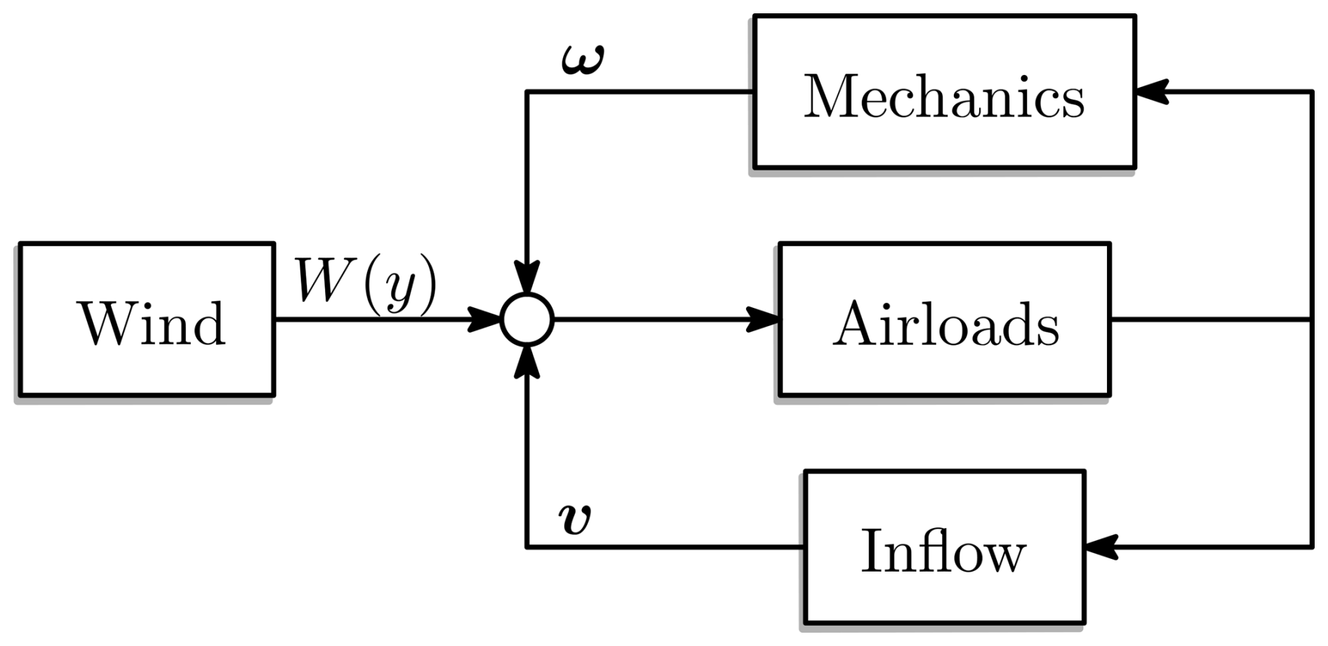
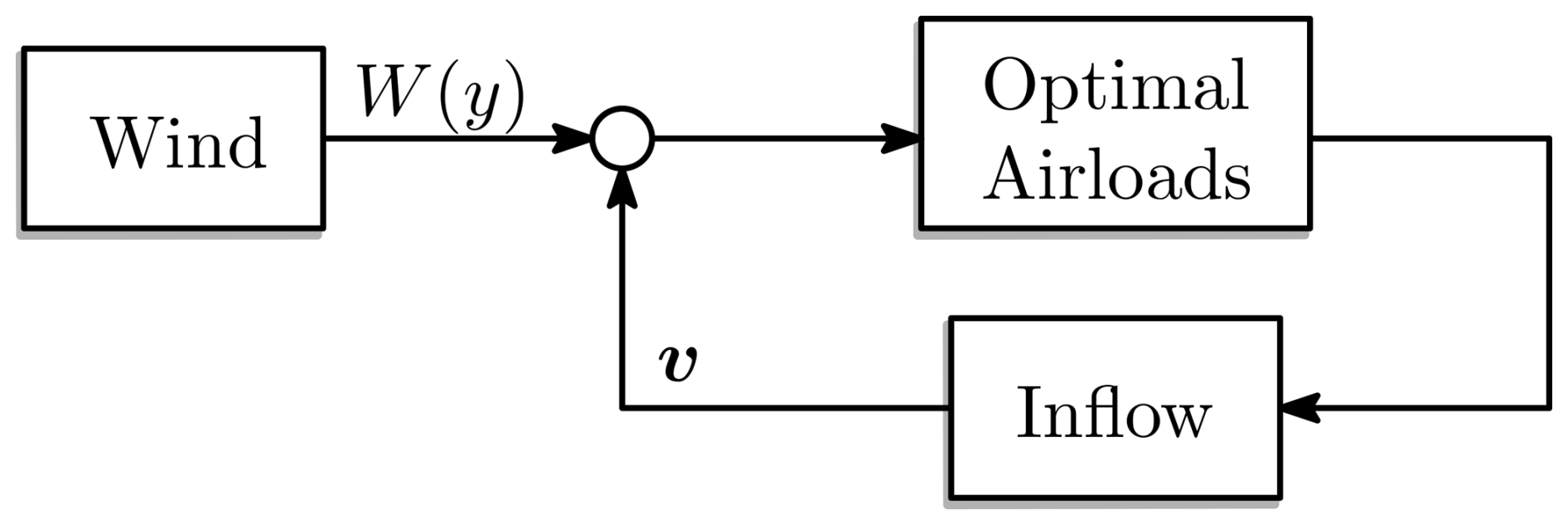
Following Matras et al. (2024), the model is decomposed as originally proposed in Joglekar and Loewy (1970), as shown in Fig. 2. The decomposition allows for a clear separation of the various submodules so that each can be modeled independently. The main input to the model, which is also the source of energy, is the freestream wind of strength W(y) with direction ψ. Combining the freestream wind, the rotation of the rotors ω and the axial-induced flows of all rotors v produces a relative velocity over the rotor blades, which are mapped to forces through the airloads module. These forces are then fed back into the mechanics and inflow modules to compute the resulting mechanical and flow perturbations. The feedback structure gives an intuitive understanding of the system behavior and also allows us to implement the multi-rotor interactions by extending the inflow and mechanical modules, while the remaining modules remain decoupled on the rotor level.
In the following, it is assumed that three critical measurements are available for each of the turbines , namely the electrical power Pn, the rotational velocity ωn and the thrust Fn. With these three measurements, it is possible to estimate the required quantities for control purposes, as is discussed later. The electrical power is assumed to be measured at the output with good estimates for the losses, such as the drivetrain and generator losses, so that the shaft power can be determined. The rotational velocity is assumed to be an accurate direct measurement from, for instance, a hall sensor. Finally, the thrust is also assumed to be a directly measurable quantity using a pressure plate between the thrust bearing and the support structure. Sideway forces are excluded for model simplicity, and as shown in Matras et al. (2023), these are often two orders of magnitude smaller than the axial forces.
3.1 Induced flows
The model developed in Matras et al. (2024) can be seen as a special case of the input coupling inflow model (Matras, 2025). It describes the relation between a column vector of mean thrust f and a column vector of mean axial flows v. The relation is found as
The matrix A describes the relation between the forces and flows and depends on the rotor layout and the skew angle. Figure 3 illustrates how the pressure forcing of two rotors is converted into a flow using the matrix A.
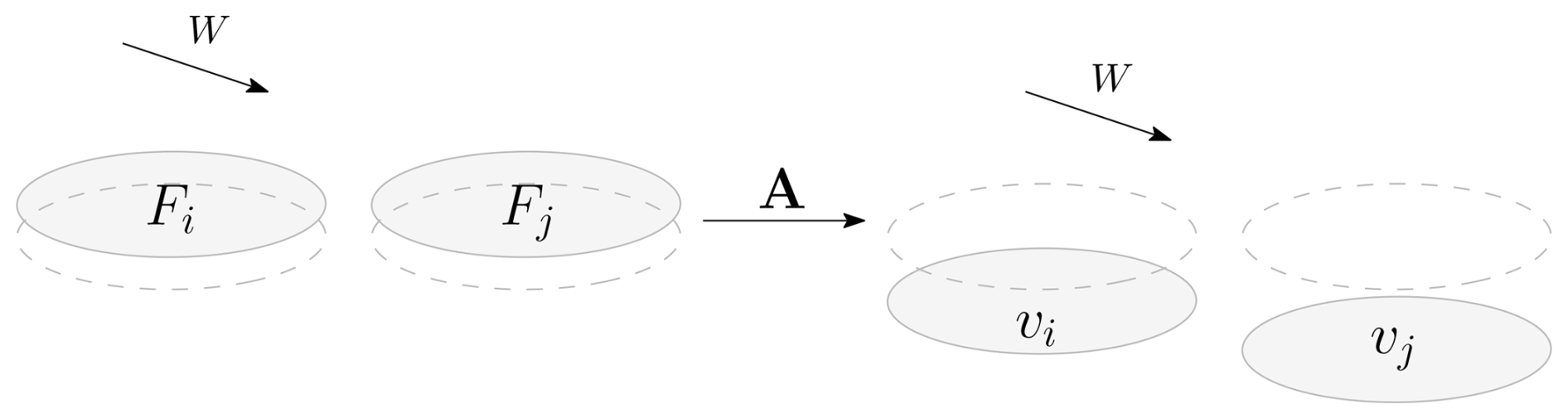
The simplest case, where all rotors are spaced sufficiently apart so that they can be considered to be isolated from one another, yields a diagonal matrix. Moving the rotors closer together adds interactions, which become visible on the off-diagonals. To include a skewed flow with an average skew angle χ, the matrix A requires an expansion in to be computed:
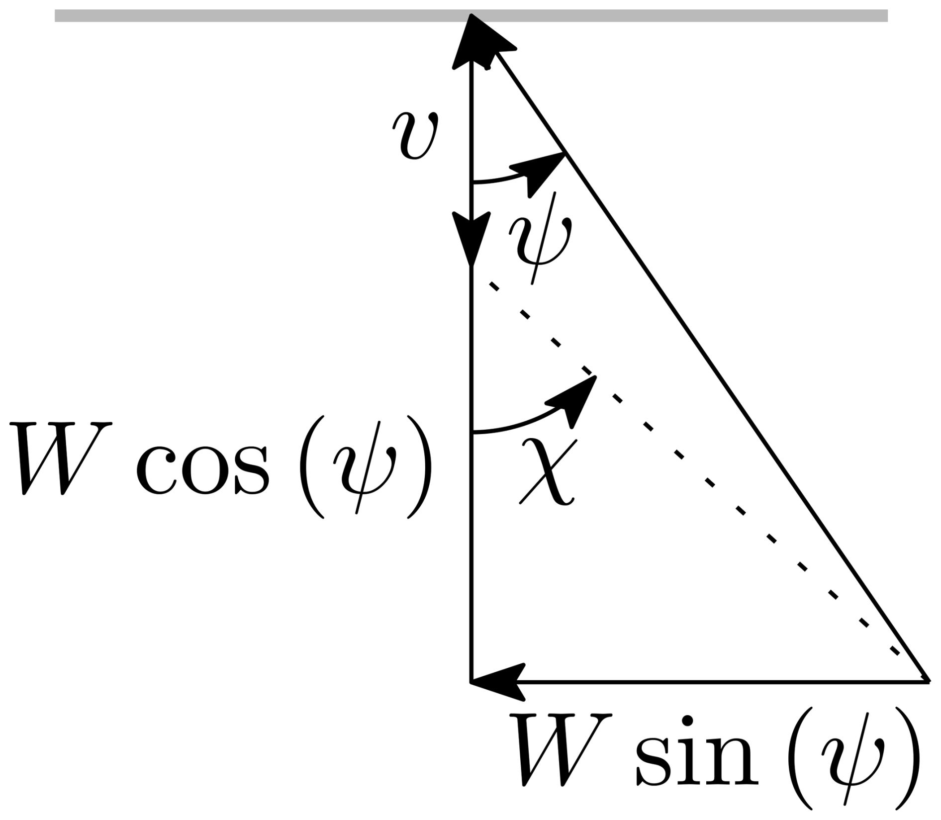
As illustrated in Fig. 4, the skew angle is defined as the angle between the axial unit vector and the net flow that passes through the rotor. The simplified model uses a global skew angle, computed on the average wind speeds of all rotors. While this can be seen as a somewhat crude approximation, it is believed to be suitable for the simplified analysis presented in this work.
A normalized example of the first two terms of the expansion of A for four rotors placed in a tightly packed square is
It is clear that the zeroth term, representing the self-influence, is constant regardless of the skew angle. The first term is skew symmetric and represents the linear interactions, in , between the rotors. A few more terms are needed for good coverage of higher skew angles, so the remainder of this work includes 10 terms for the modeled multi-rotor.
3.2 Rotor airloads
In accordance with the rest of the model, the airloads will also only consider mean axial linear and rotational velocities as inputs, generating axial linear and rotational forces F and q, respectively. The modeling of the airloads is further simplified by using dimensionless inputs and outputs. The input is considered to be a slightly modified tip speed ratio (TSR) given by
where represents the net axial flow through the rotor and not only the freestream component as in the typical definition of the TSR. The fixed-pitch rotor model only takes this TSR as input. At the optimum, where momentum theory predicts , the modified TSR becomes times the traditional TSR.
Similarly, the outputs are also made dimensionless by using the thrust coefficient
and torque coefficient
scaled by κ=10 to make it of a similar magnitude to the thrust coefficient. Here, ρ describes the fluid density and R the rotor radius.
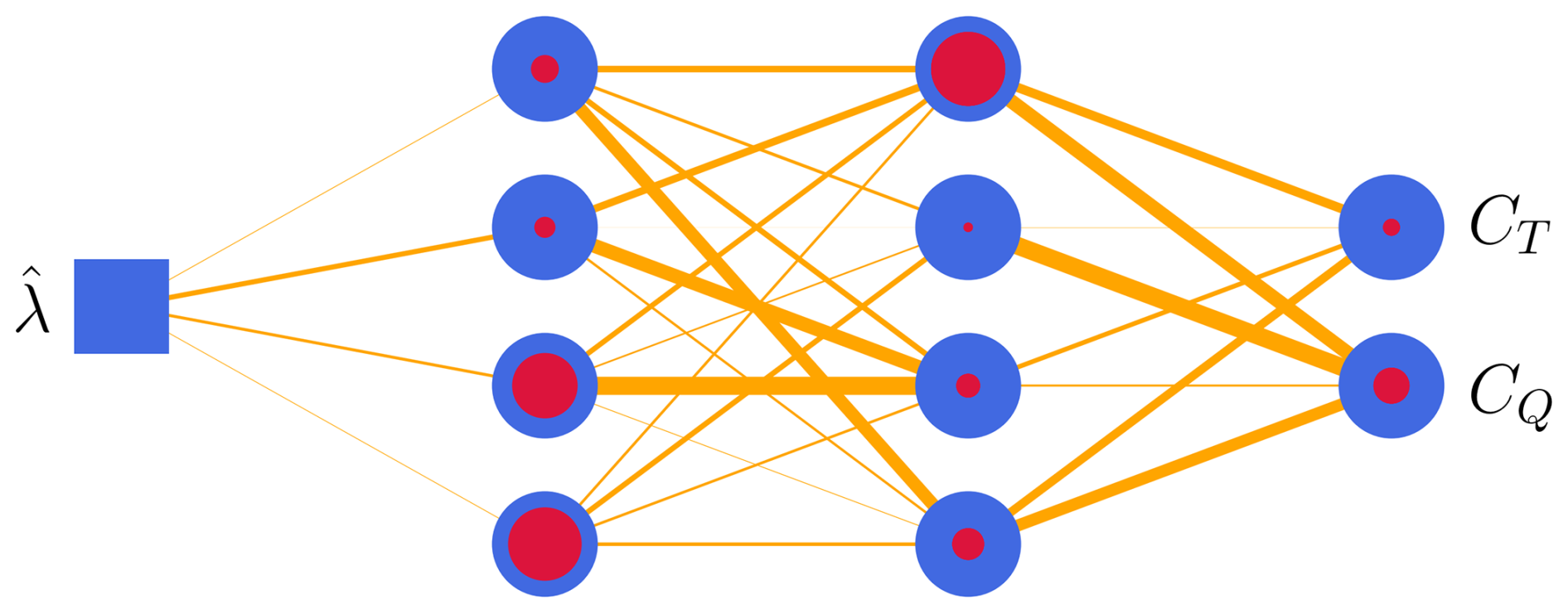
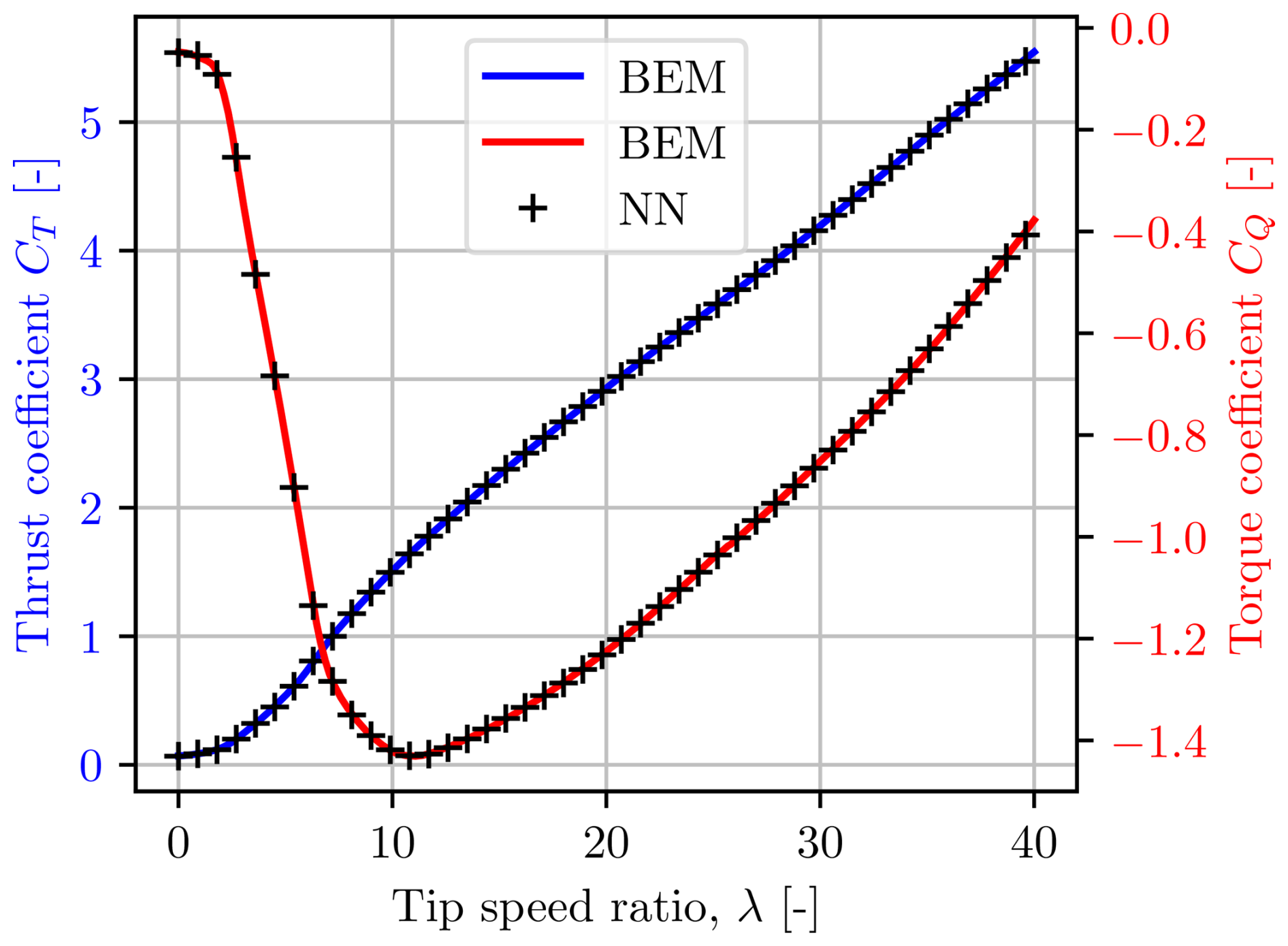
Using the approach from Matras et al. (2023), the input–output relation for the airloads was found employing the blade element method (BEM) for using the data presented in Jonkman et al. (2009). The dimensionless model then makes it possible to scale the relation to the desired rotor size. Continuing as in Matras et al. (2023), the BEM data are then used to train a neural network implemented in Flux (Innes et al., 2018; Innes, 2018) using the AdaBelief (Zhuang et al., 2020) backpropagation algorithm in Julia (Bezanson et al., 2017). Thorough tuning of model dimensions, activation functions, weights and biases revealed the model shown in Fig. 5, where the blue square represents the input, the blue circles represent neurons, the thickness of the lines represents the weight of the connections and the red dots represent the bias. The activation function for the two hidden layers is the tanh function, and the output layer uses a unitary activation function.
Mathematically, the artificial neural network with weights W and biases b is given by
As expected from the results presented in Matras et al. (2023), the performance is excellent, as shown in Fig. 6.
3.3 Mechanics
Only the fundamental mechanics required to represent a multi-rotor system at steady state are considered here. These are the yaw moment and the net bending moment around the base:
where xn and yn are the x and y positions of rotor n. The steady-state nature of the model allows the rotational velocity of rotor n, ωn to be set directly, as the appropriate torque will be produced by the generator to maintain steady state,
3.4 Wind
The final block in Fig. 2 that needs to be modeled is the wind. Assuming a horizontally constant freestream field of strength W(y) and direction ψ, one only needs to model the wind shear. This endeavor has been undertaken many times previously; therefore the well-known power law profile presented in Manwell et al. (2010) is used,
The reference velocity Wr at height yr=2 m is scaled to height y, and the relation can be adapted to any particular site by adjusting α. Following Schlichting and Shapiro (1968), we use .
This section investigates the unconstrained operation of a multi-rotor wind turbine that maximizes the produced power.
4.1 Control law
The MPPT algorithm is an excellent candidate for controlling a single-rotor wind turbine in the unconstrained region (Abdullah et al., 2012). By considering the steady-state operation around the optimum, taking only the rotational velocity as a variable, an optimal and stable solution for the generator torque is found as
The optimal power coefficient and the corresponding traditional TSR λ* have to be computed beforehand. When applying the MPPT algorithm to each individual turbine in a multi-rotor wind turbine without considering the interactions, this is called distributed maximum power point tracking (DMPPT).
During strictly axial flows, the DMPPT algorithm is equivalent to solving the optimization problem
for the simple model considered in this work. This optimization problem was implemented in was implemented in Julia (Bezanson et al., 2017) using the JuMP (Dunning et al., 2017) package and solved using the IPOPT solver (Wächter and Biegler, 2006).
4.2 Operation characteristics
At steady state without constraints, it is optimal for the multi-rotor system to be aligned with the wind. The inflow model predicts no interactions in this case, making the DMPPT optimal. This is indeed verified by comparing the results from the DMPPT to the numerically optimal solution by solving Eq. (13).
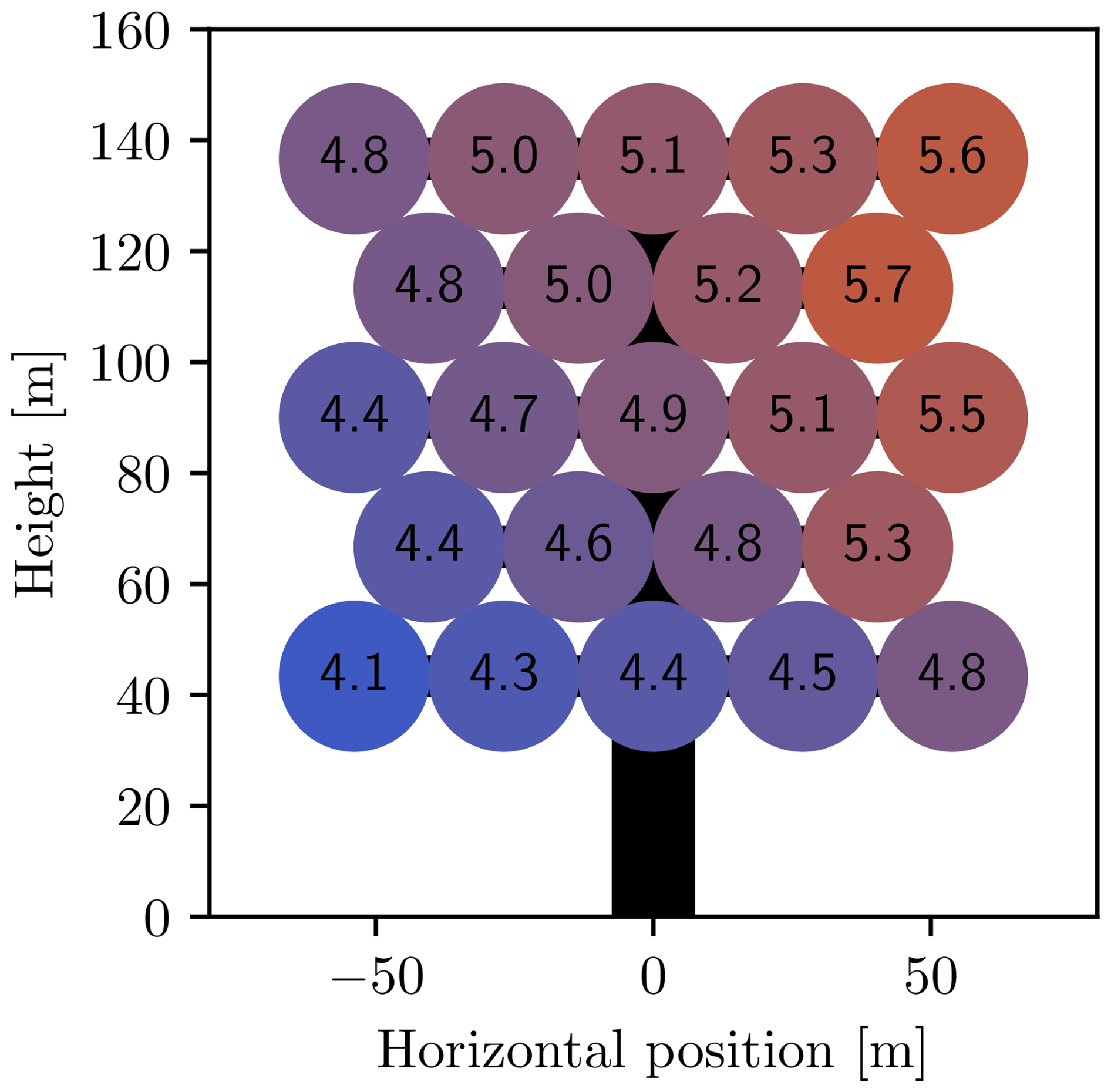
Figures 7 and 8 show the powers and thrusts for the unconstrained case with an ambient wind speed of 9 m s−1 at the array center. The effect of the wind shear is clear, as both the thrust and the power increase with height.
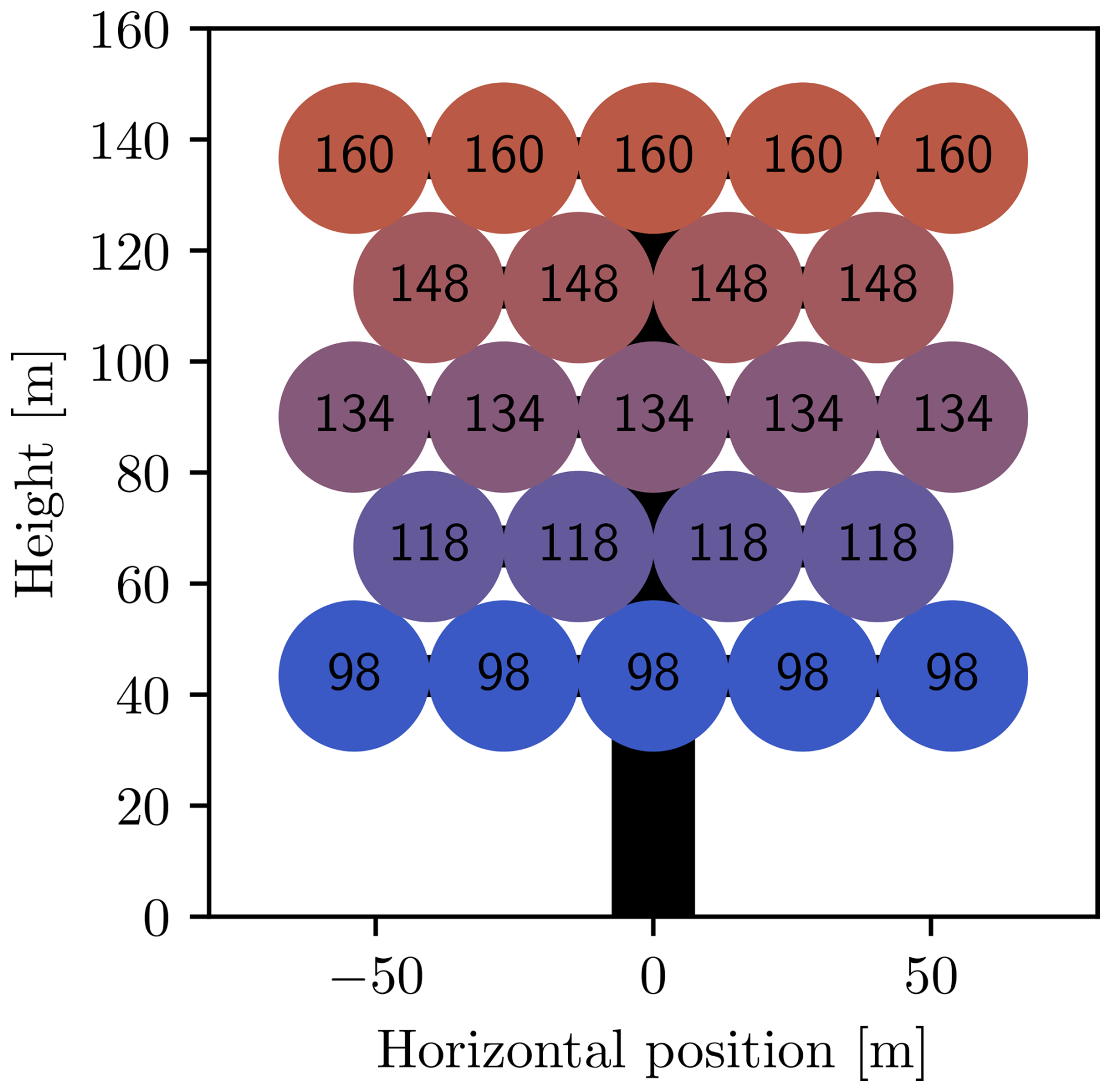
Figure 7Power (in kilowatts) of multi-rotor wind turbine in wind shear, with 9 m s−1 wind velocity at the array center.

Figure 8Thrusts (in kilonewton) of multi-rotor wind turbine in wind shear, with 9 m s−1 wind velocity at the array center.
4.3 Yaw moment
As long as the individual wind turbines can be considered decoupled, the analysis is straightforward as it strongly resembles a gathering of single-rotor systems, which are described in the literature. However, once the aerodynamic interactions come into play, this changes. In an effort to analyze these interactions, they are provoked by enforcing a yaw offset, which in turn generates horizontally varying operating conditions across the array. These changes will in turn result in varying thrust distributions, affecting the horizontal stability of the multi-rotor wind turbine.
Consider the case in which the multi-rotor wind turbine is not aligned with the flow. Now, the side that is closest to the wind, the upwind side, extracts energy from the wind, reducing the axial wind speed. Because the multi-rotor is not aligned with the flow, this means that some component of this slightly perturbed, slowed down part of the flow will traverse onto the downwind turbines. This effect multiplies itself the further downwind one travels on the multi-rotor. Figure 9 illustrates the mean net axial flow through each rotor with a 45∘ yaw misalignment. The upwind side is to the right in the figure, and the interactions can be seen clearly.
When operating in the unconstrained region, in which the thrust correlates with the ambient wind speed, this means that the thrust also decreases downwind. Fortunately, this effect produces a restoring moment, which tries to realign the multi-rotor with the wind, as shown in Fig. 10. At the peaks, the restoring moment is approximately equivalent to moving the center of the thrust 3 m upwind, which is slightly more than 2 % of the multi-rotor width. A torque of a similar magnitude can be obtained by turning off one of the upper and outermost rotors when the wind turbine is aligned with the wind.
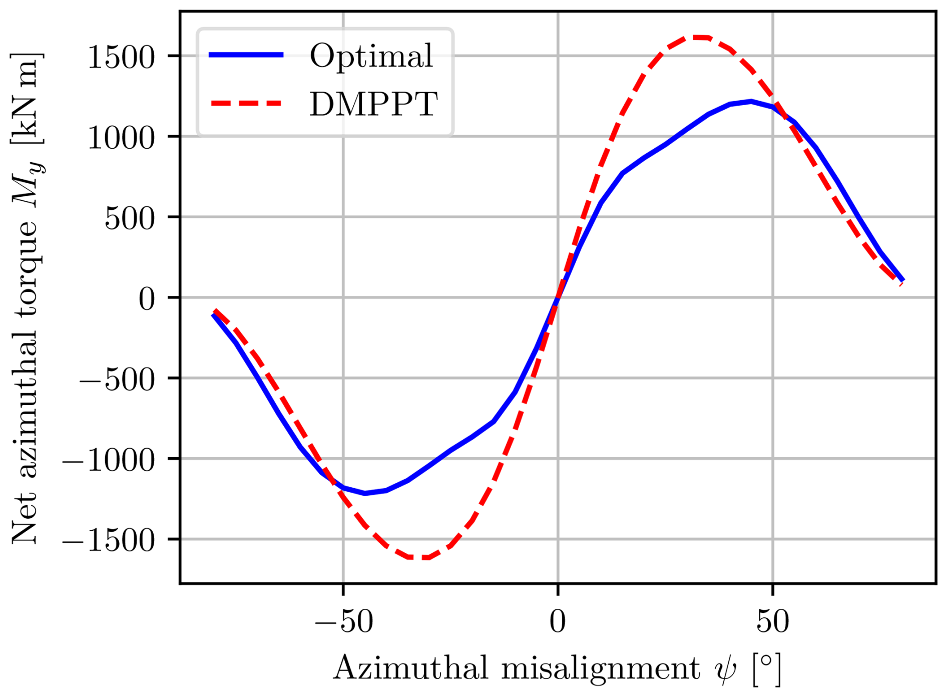
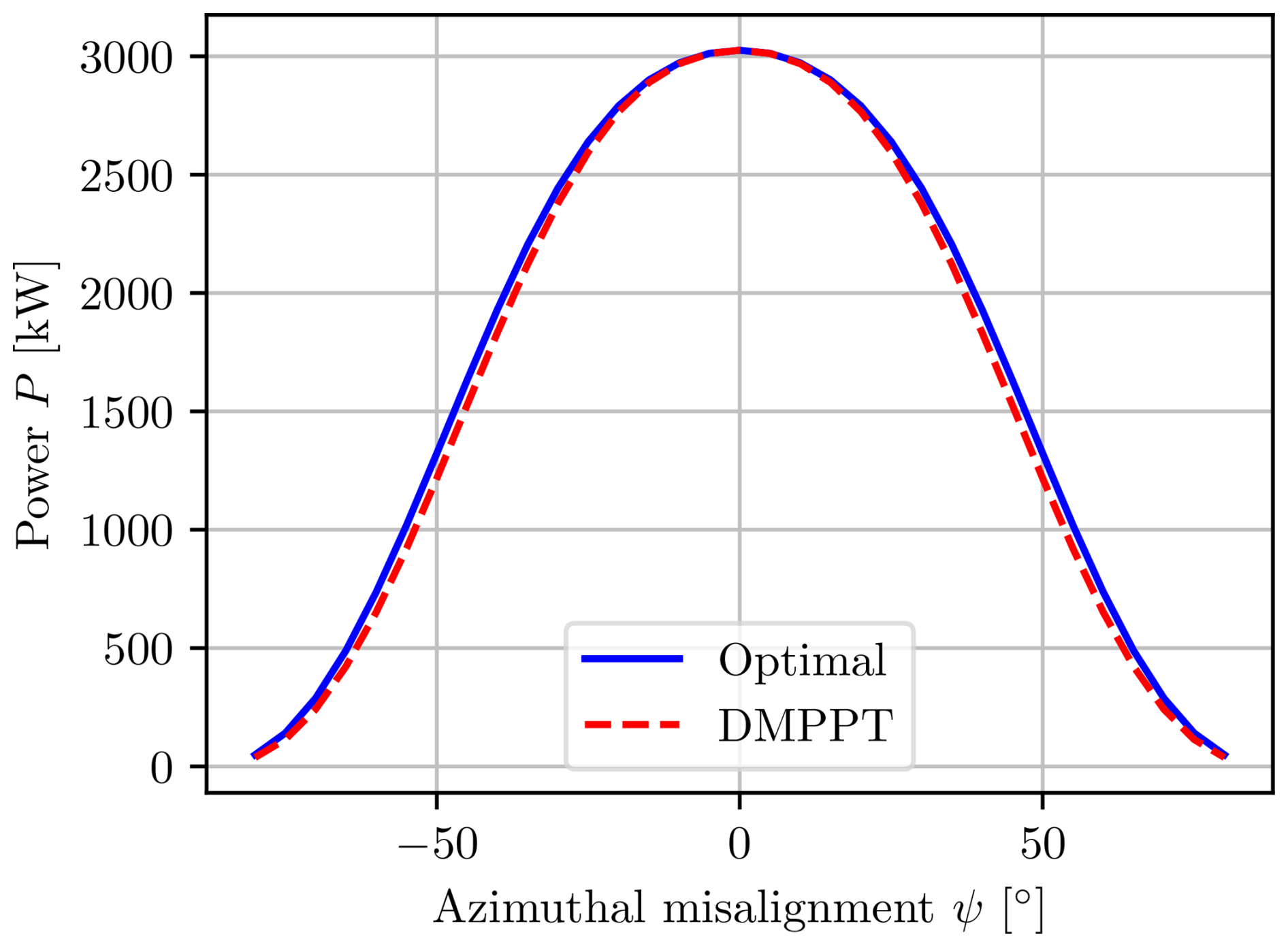
The interactions also cause a reduction in total power, which increases with increasing skew angle, as shown in Fig. 11. Both figures show the results obtained with the DMPPT algorithm and with the numerically optimal solution. While the general characteristics are the same, there are some differences. The optimal solution is able to leverage the interactions to increase the total power by a maximum of about 2 % of the rated power compared to the DMPPT algorithm that tries to maximize the power for each rotor independently. The leveraging of the interactions also has the effect of reducing the yaw moment drastically for intermediate misalignments, as the optimal solution is to reduce the power on the upwind rotors so that the wind has more kinetic energy available for the downwind rotors. This results in a more even thrust distribution, which drastically affects the yaw moment because the thrusts are weighted by the horizontal distances to the center of the wind turbine.
The restoring moment is necessary but not sufficient to determine if the multi-rotor is at a stable equilibrium when it is aligned with the wind. In addition to the restoring moment, one would also need to consider the dynamics of the total system to form a sufficient argument. However, it is believed that with the appropriate utilization of dampers, the equilibrium can be made stable if it is not already. The damping effect could be implemented either physically or digitally using differential thrusting. Differential thrusting can be achieved by manipulating the generator torques so that the corresponding rotors change their thrusts, effectively manipulating the net yaw moment. In this sense, the differential application of generator torques can be seen as a proxy for a yaw actuator.
When the stability of the system is ensured, one can conclude that the DMPPT algorithm exhibits a variation in self-optimizing control (Skogestad and Postlethwaite, 2005), which will always try to realign the multi-rotor with the freestream wind.
The second and maybe more interesting operating region is the constrained region in which various physical constraints need to be respected. In contrast to a single rotor, the multi-rotor has constraints both on the rotor level, such as maximal power or thrust, and on the multi-rotor level, such as the net yaw moment and bending moment.
5.1 Control law
The DMPPT algorithm is no longer valid in the constrained case, and the general numerical optimal solution presented in Eq. (13) needs to be expanded to include constraints,
The star symbol is used to denote a reference value. A small penalty for the bending moment, with , is added to guide the solution towards the optimum, which also reduces the bending moment without significantly influencing the power. The importance of this is shown later.
5.2 Individual power constraints
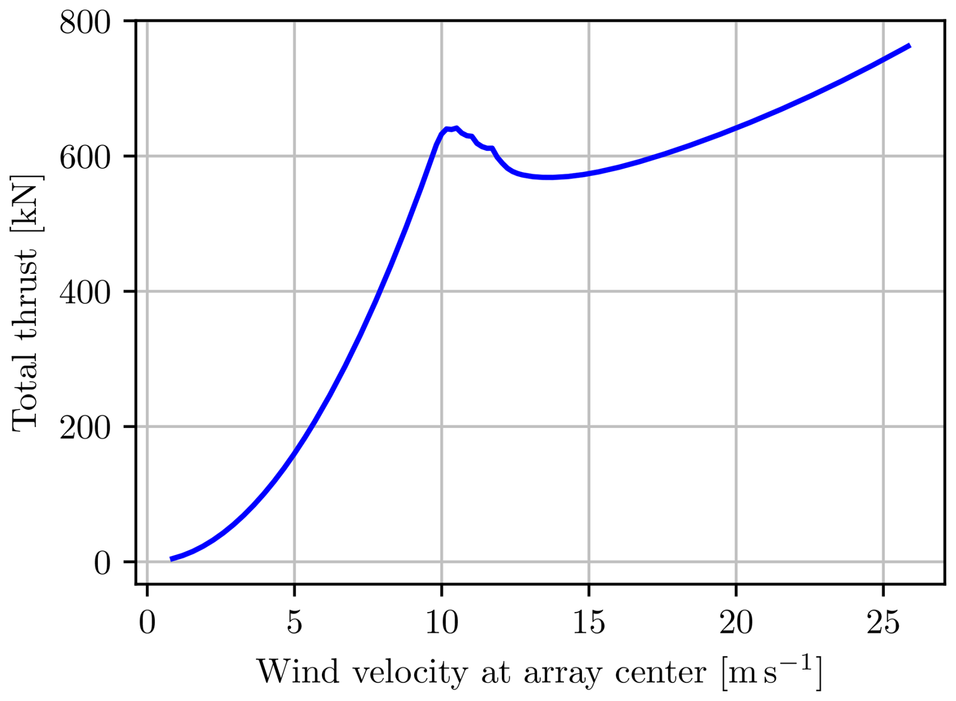
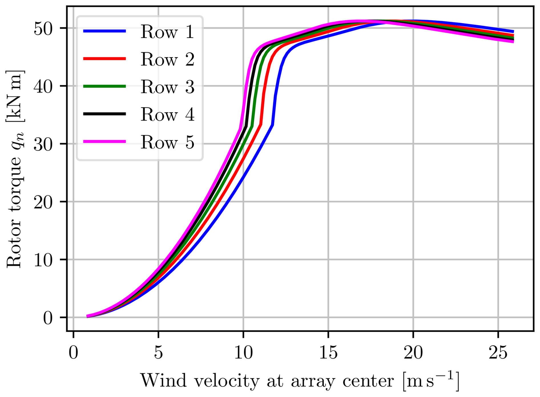
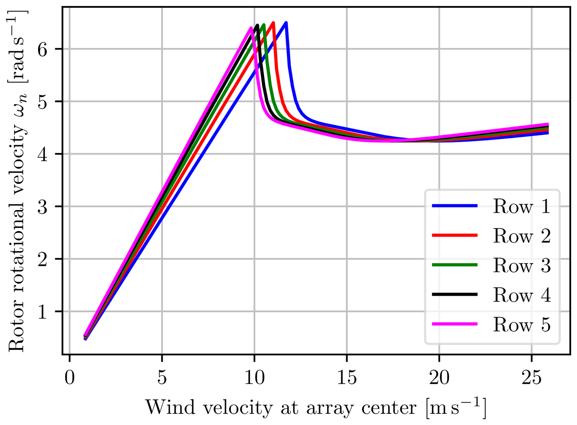
Figures 12 to 17 show varying characteristics of the multi-rotor when aligned with the wind, found at the solution to Eq. (14), with the power constraints on each individual turbine from Eq. (15).
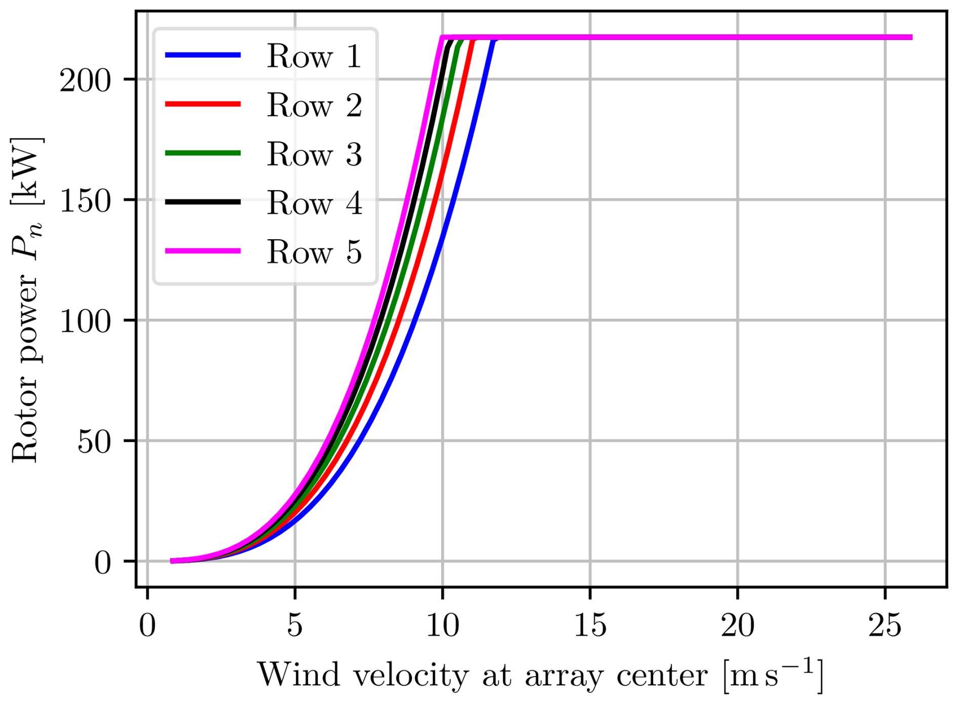
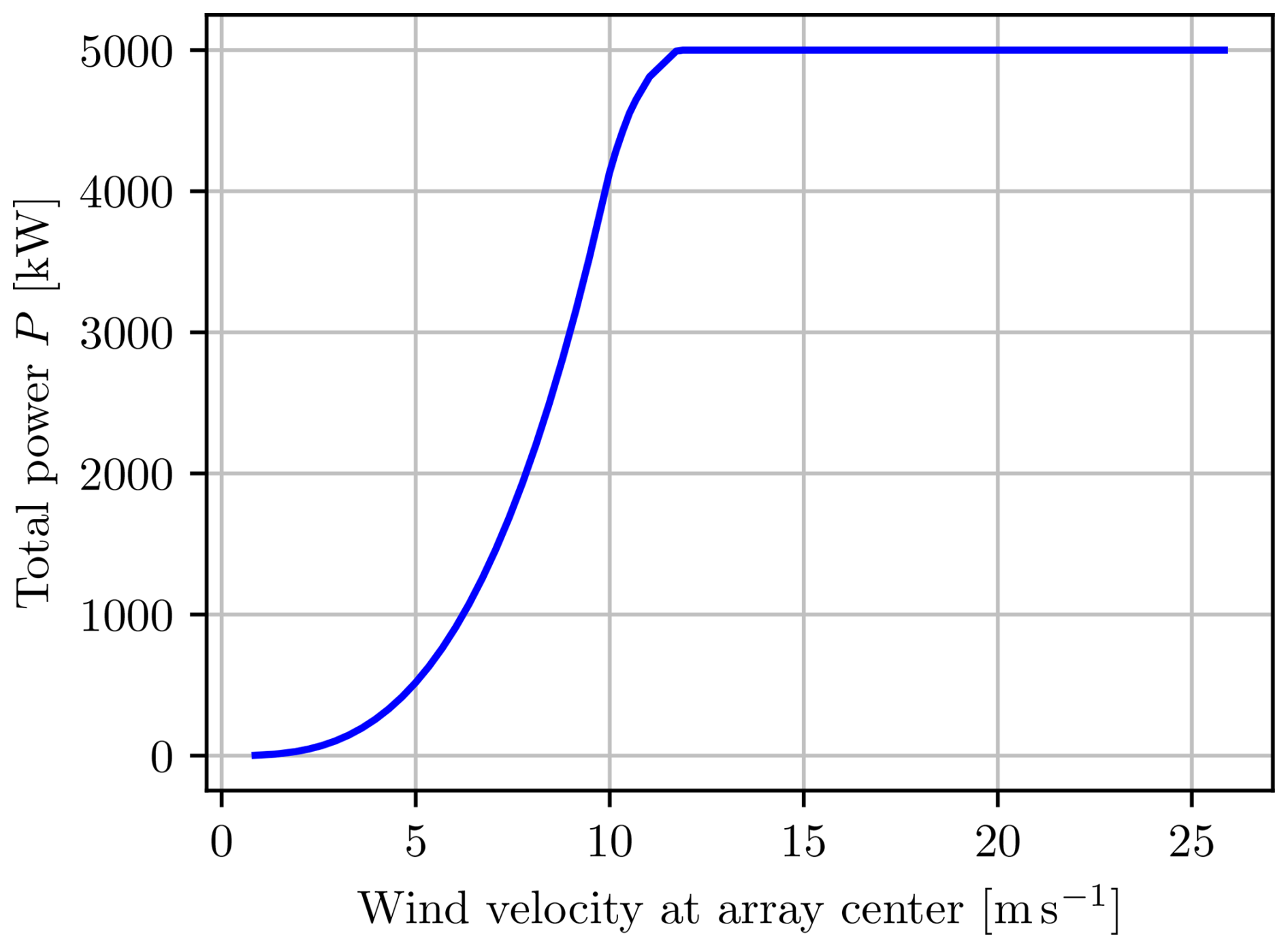
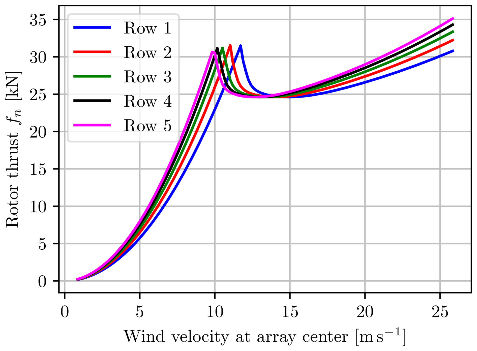
The effect from the wind shear is clearly visible, affecting each row of the multi-rotor differently. Intuitively, the top row of rotors, row 5, reaches the power constraint first, as shown in Fig. 12, while the remaining rows follow in order. An advantageous consequence of this is that the total generated power shown in Fig. 13 has a smoother transition from the unconstrained to the constrained region. The same effect is visible for the thrusts in Figs. 14 and 15.
Interpreting the above findings, one could conclude that the rotors in one row could advantageously differ from the rotors in the other rows. For instance, the upper rotors should be optimized and rated for higher wind velocities than the lower rotors. Such an adjustment could increase the total generated power but consequently also the loads on the support structure. This would also reduce the smoothing behavior seen when each row hits the constraint at slightly different velocities.
Figure 17 shows the advantage of including the small penalty on the bending moment in Eq. (14) because once the fixed-pitch rotor reaches the rated power, it can decrease the power by either increasing or decreasing the TSR, as shown in Fig 6. Increasing the TSR would further increase the thrust, which is not desired, so the other solution found by decreasing the TSR is sought and used, as can be seen in Figs. 17 and 14.
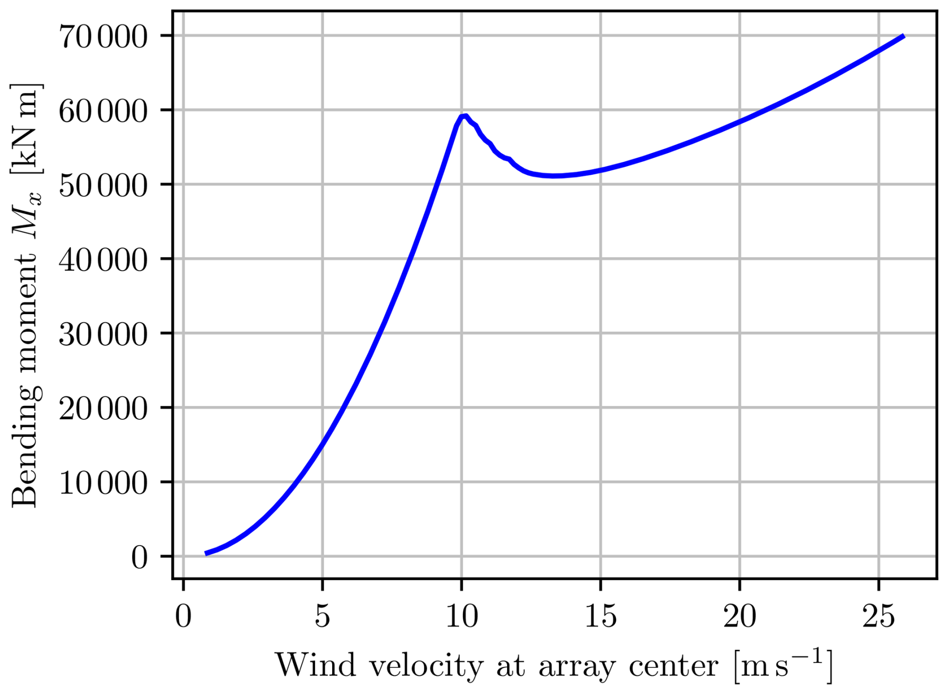
5.3 Net bending moment constraint
In addition to placing constraints on the generated power to protect the drivetrain, generator and power electronics, a net bending moment constraint can also be added to protect the support structure. The net bending moment constraint for a multi-rotor can be seen as a weighted equivalent to the thrust constraint for a single rotor. Comparing the total thrusts from Fig. 15 to the unconstrained net bending moment in Fig. 18, one can clearly see the resemblance between the two values, but the net bending moment puts a higher weight on the rotors that are placed higher because they increase the loading on the structure more.
One can easily include the net bending moment constraint, Eq. (18), with Nm in the optimization problem. The solution to Eq. (14) with Eqs. (15) and (18) for a wind velocity of 17 m s−1 at the center of the array produces an allocation that results in powers and thrusts, as shown in Figs. 19 and 20, respectively. As can be seen, most rotors operate at the power constraint, and only the top rotors start reducing thrusts by slowing down the rotors, starting from the middle and going outwards. The top rotors are turned off first because they have the greatest impact on the bending moment. This results in a total power reduction of 8 %. The relation between power and thrust in the current case, where power is limited by reducing the TSR, enforces an L1 penalty on the system, favoring sparsity rather than reducing the power equally on all rotors.
In the presence of pitch control, this issue is typically mitigated by pitching the blades, so no power is lost.
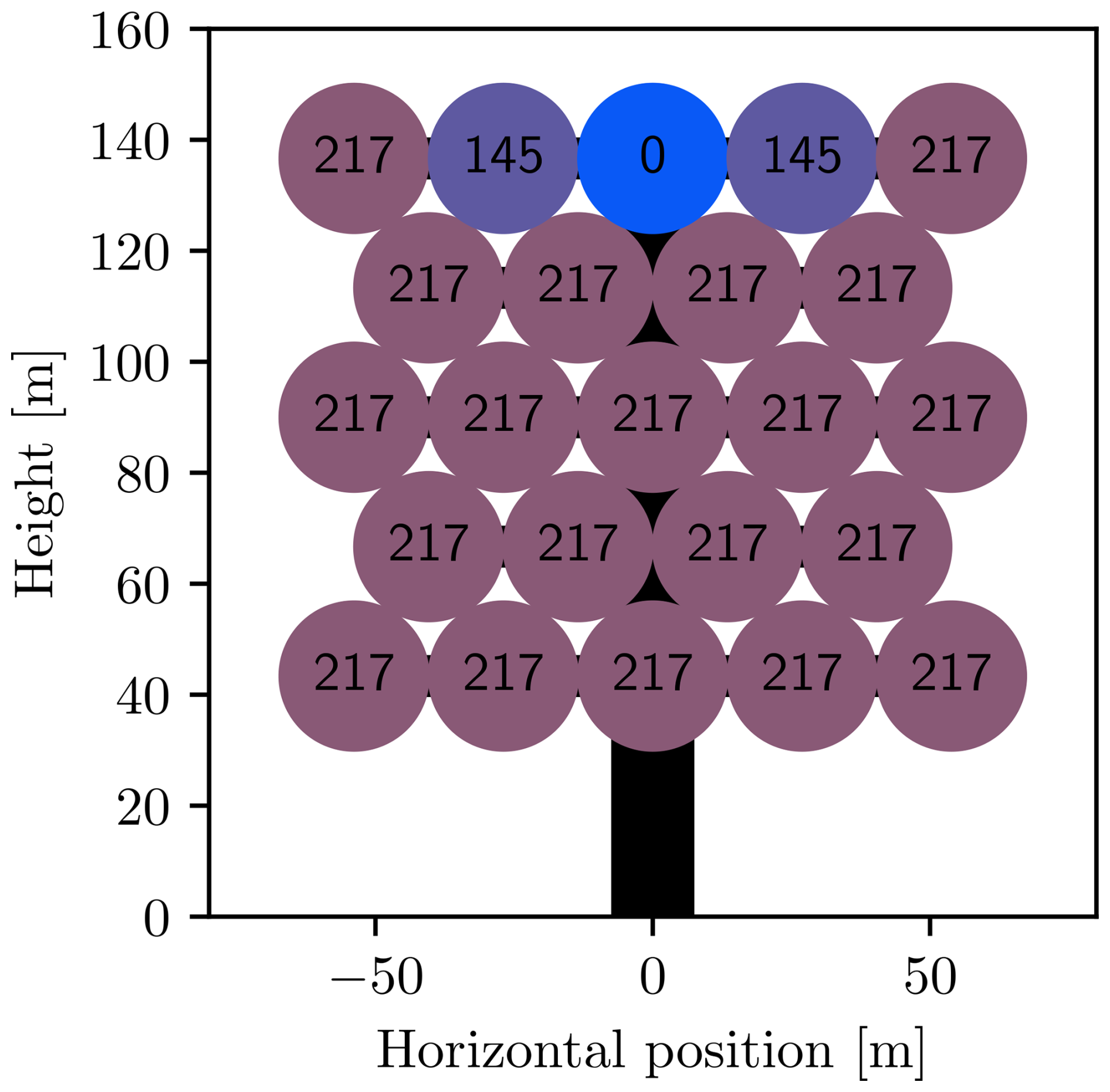
Figure 19Power in kilowatts for allocation with individual power and net bending moment constraints.
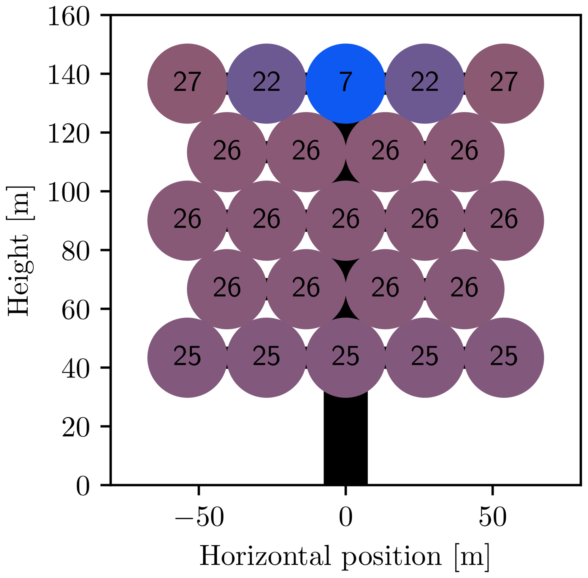
Figure 20Thrusts in kilonewtons for allocation with individual power and net bending moment constraints.
It is interesting to note in Fig. 20 the presence of a thrust due to the surface area of the rotor, even though the rotor does not produce any power.
5.4 Net yaw moment constraint
The final constraint considered is the net yaw moment constraint. Its importance might not be obvious, but one example of its importance is the case in which one rotor fails, after which the remaining rotors might produce an undesired net yaw moment. Including the constraint, Eq. (17), in the optimization problem, one can easily compensate for failures by reducing the thrusts appropriately on the opposing side. Figures 21 and 22 show the powers and thrusts for a multi-rotor, where rotor number 13 has suffered a failure and is not spinning. The example uses a wind velocity of 17 m s−1 at the array center. As found by the optimal control problem, the best thing to do is to reduce the thrust on the outer and uppermost rotor on the opposite side, rotor number 19. This way the smallest possible reduction of power, 7 %, is achieved while at the same time reducing the bending moment to a minimum.
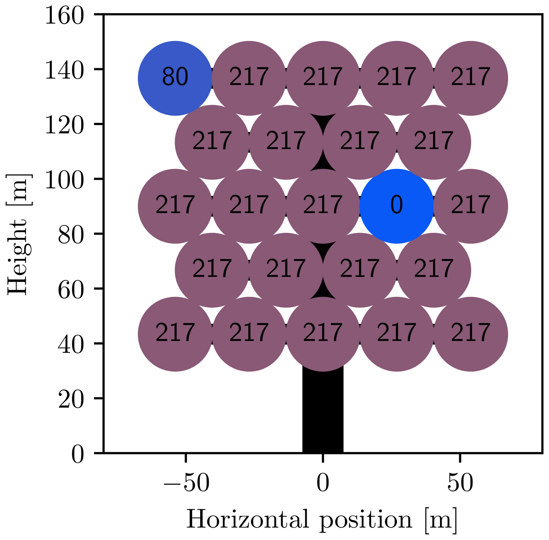
Figure 21Power (in kilowatts) for allocation with individual power and net yaw moment constraints.
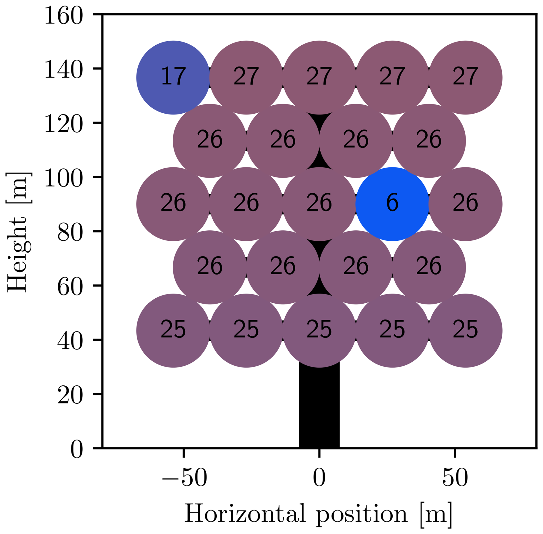
Figure 22Thrusts (in kilonewtons) for allocation with individual power and net yaw moment constraints.
The control strategy for the general case presented in the optimization problem (Eqs. 14 to 18) can be too computationally complex to solve for practical real-time applications. This section suggests some high-level control schemes, utilizing multi-rotor properties that are predicted by the proposed model, which should be viable for real-time applications.
6.1 Scheduled maximum power point tracking
The DMPPT algorithm developed for the unconstrained case is not applicable when there are active constraints. Assuming that each rotor is constrained by only an individual power constraint, the DMPPT algorithm can be redesigned to respect this constraint by reducing the power once it reaches the rated power. The main issue with the redesigned controller is that the power constraint results in a non-minimum phase (Dalala et al., 2013). After the rotor reaches the rated power, the power is controlled by the generator torque, which has to increase briefly, possibly exceeding the power constraint, to reduce the rotational rate sufficiently for the steady-state power to be lower, after which the generator can reduce its torque and power. Luckily, similar issues have been investigated and solved by Barzegar-Kalashani et al. (2023) and Dalala et al. (2013), so it is believed that such a controller can be successfully designed and implemented.
In contrast to the DMPPT algorithm, the current approach makes the somewhat unconventional assumption of the net flow through the rotor being available as either a measurement or an estimate. The net flow is used as input to the control algorithm, which, based on this, returns the optimal rotational velocity of the rotor. A high-gain controller can then be used to control the system to follow this reference. This type of control scheme is called the scheduled maximum power point tracking (SMPPT) controller.
Figure 23 shows the optimal relation between the net flow through the rotor and the rotational velocity that maximizes the power until the power constraint is reached at around 7.5 m s−1, after which the power is kept at the constraint. The SMPPT algorithm relies heavily on this relation, which has to be tuned to each physical system by formulating an accurate model and computing the optimal solutions numerically. With these results at hand, one can then model the relation using a neural network.
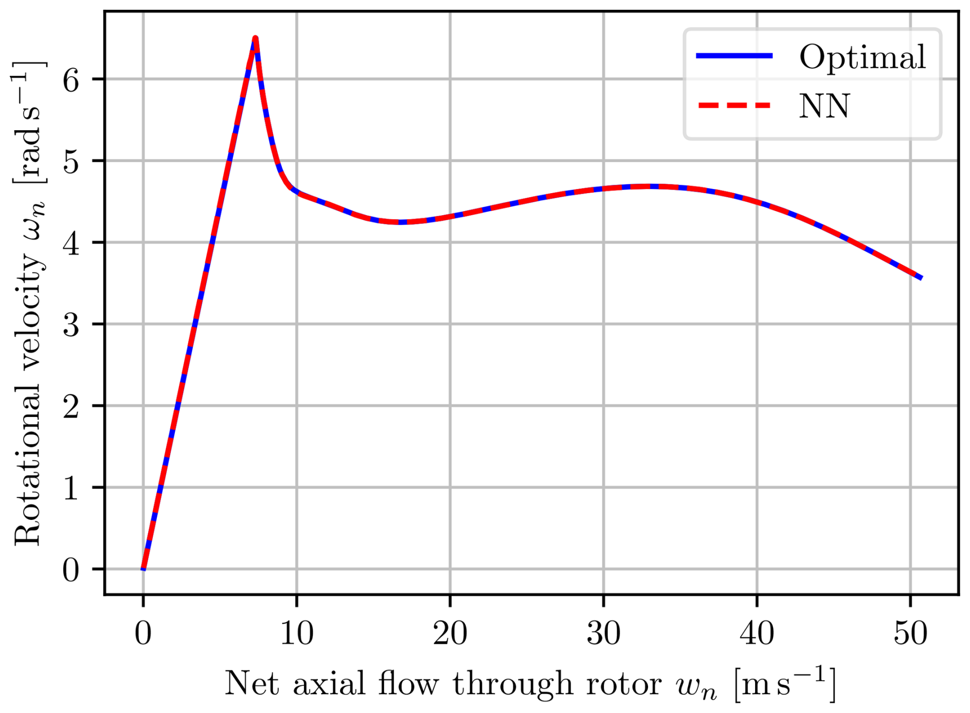
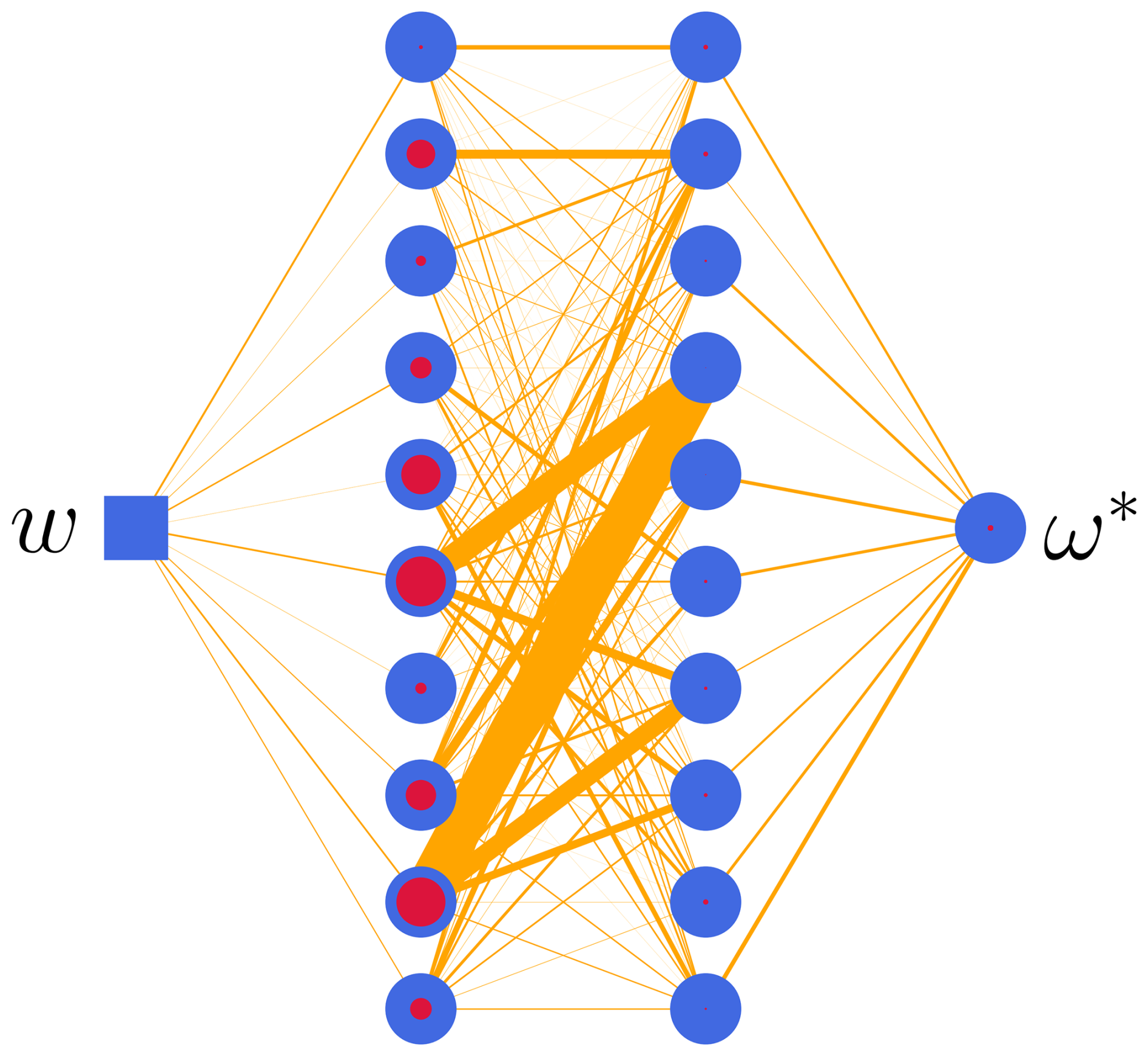
A neural network, as shown in Fig. 24, was designed, implemented and trained to reproduce the relations from Fig. 23 for net axial flows from 0.01 to 50 m s−1. The same framework as the one for the airloads was used for implementation and training.
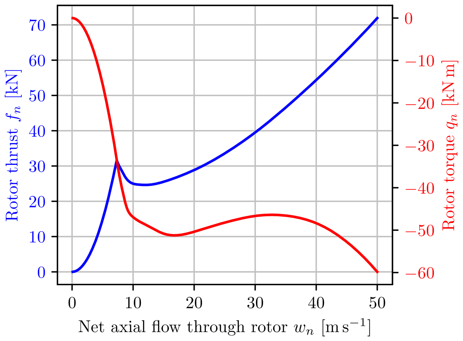
6.1.1 Thrust and torque schedule
An interesting feature arises when employing the SMPPT controller to the feedback model shown in Fig. 2: the airloads can be substituted for the optimal airloads, which include the mechanics, since at steady state the rotational velocities are instantly determined by the net flow. This gives a direct map from the net flow to the generated forces, as shown in Fig. 25, simplifying the system block diagram to Fig. 26. Assuming a multi-rotor with many reasonably small rotors, one can still describe dynamic cases with the optimal airload simplification because the dynamics are governed by the inflow, as shown in Matras and Pedersen (2024).
6.1.2 Restoring moment
Similarly to the DMPPT, the SMPPT algorithm also generates a yaw moment when applied to a multi-rotor system that is not aligned with the freestream. In the unconstrained case, the SMPPT is equivalent to the DMPPT, for which the restoring moment has already been shown. An example of the power-constrained case with an ambient wind speed of 20 m s−1 at the array center, meaning that all turbines need to limit their power to comply with the constraint, is shown in Fig. 27. For modest misalignments, the expected restoring moment is present, but at large misalignments, the net yaw moment becomes destabilizing. The somewhat abrupt changes in the graph for the optimal solution are believed to be due to the different rows reaching the destabilizing misalignment at slightly different yaw misalignments.
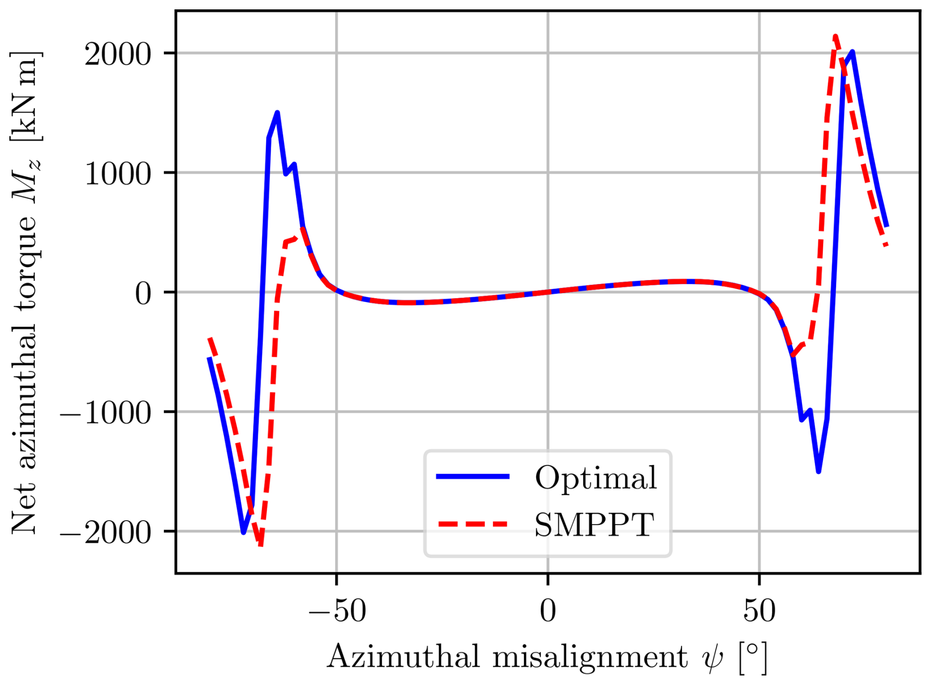
Figure 28 shows the resulting net power as a function of the yaw misalignment. One can clearly see that by increasing the misalignment, one can effectively reduce the power. For single-rotor systems this technique is known as furling, a term which is also used for multi-rotors.
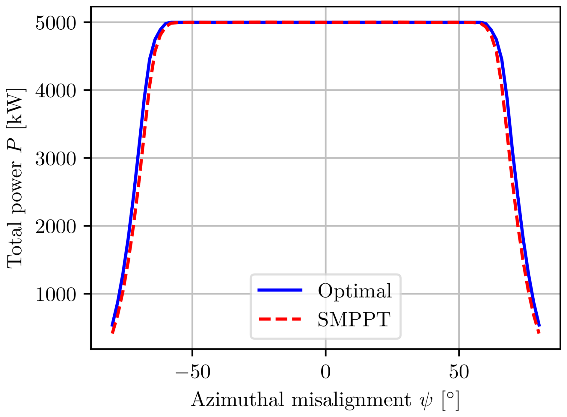
An interesting observation in Figs. 27 and 28 is that the SMPPT controller performs identically in terms of power and net yaw moment to the numerically optimal solution of the multi-rotor problem for all main operating conditions, with the major difference being that the SMPPT controller is almost trivial to compute. This greatly simplifies the control, as one can employ the SMPPT controller, completely disregarding the interactions, and still operate optimally as if one were to include the complex model with all interactions, at least at steady state with yaw misalignments that are not too large.
6.2 Furling scheduled maximum power point tracking
The SMPPT algorithm presented in the previous section gives promising results in the individual power-constrained case. In addition to constraining the power, it is often also desirable to minimize the structural loads. This can be achieved by utilizing furling, which reduces not only the power, but also the thrust loading, as the axial component of the wind is reduced.
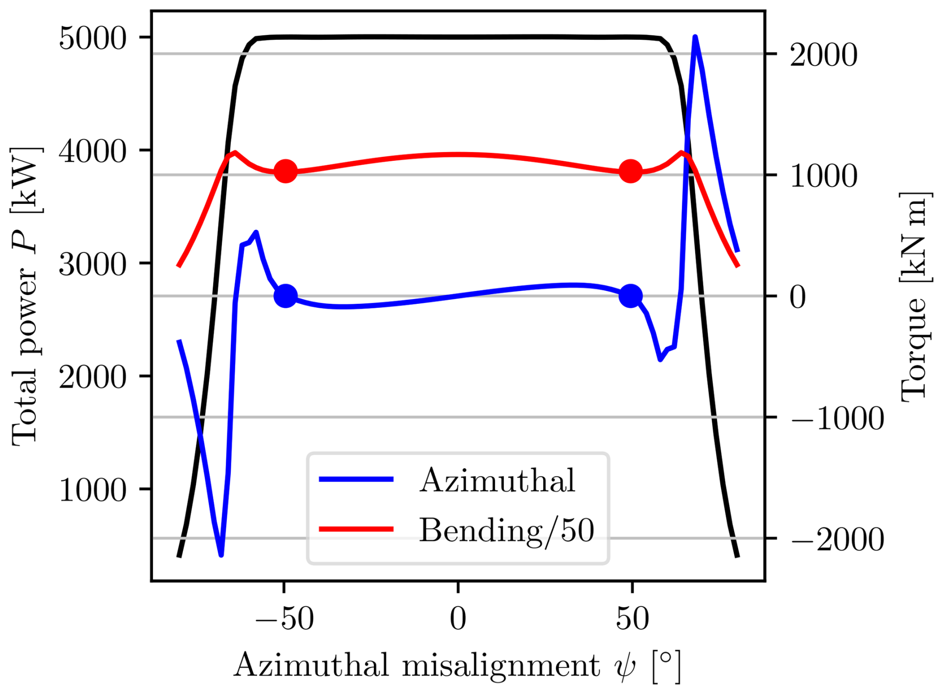
Consider the merged results from Figs. 27 and 28, as shown in Fig. 29. One can clearly see the blue dots marking the yaw misalignments that produce a zero-yaw moment while still producing maximum power. This is an advantageous equilibrium, even though it is unstable. The red dots mark the yaw misalignment where the power per bending moment is maximized, and it is of great interest that these points almost coincide with the unstable roots of the yaw moment.
Generalizing the results from Fig. 29 to a variety of velocities, one can compute the yaw misalignment required to achieve a zero-yaw moment and maximum power per bending moment at any given velocity. The results of such an analysis are shown in Fig. 30, where the case with no yaw misalignment is also considered, the SMPPT algorithm. The blue line represents the line of the zero-yaw moment, while the red line represents the misalignment where the power per bending moment is maximized. It is clear that the zero-net-yaw-moment misalignment almost coincides with the optimal solution where the power per bending moment is maximized for all freestream wind velocities.
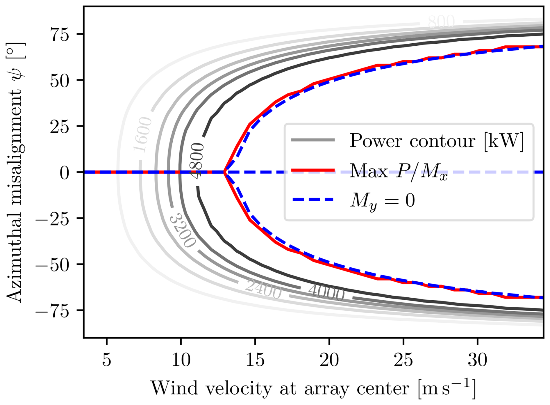
Concluding the findings, one can approximate the optimal solution to the problem
by choosing the appropriate root of the yaw moment, namely the unstable equilibrium, rather than solving a complicated global numerical optimization problem. Furthermore, each individual multi-rotor wind turbine can still be decoupled using the SMPPT algorithm. The main challenge lies in keeping the multi-rotor at the unstable equilibrium, which can be done using a variety of techniques based on either differential thrusting or some sort of yaw actuator.
The SMPPT algorithm, in cooperation with a global governor that ensures the operation at the optimal root of the net yaw moment curve, is named the global governor scheduled maximum power point tracking (GGSMPPT) algorithm. As in the unconstrained case, such a control strategy is a self-optimizing control scheme following the definition of Skogestad and Postlethwaite (2005).
Based on simulations of other rotor layouts and counts, it is believed that the multi-rotor properties required for the GGSMPPT controller to work are a general phenomenon in multi-rotor wind turbines with at least one pair of vertically aligned and horizontally spaced rotors.
Three control algorithms for the control of multi-rotor systems have been proposed:
-
the general numerical optimization problem in Eq. (14);
-
the SMPPT algorithm for the case with individual power constraints;
-
the GGSMPPT, which also reduces the net yaw loads by furling.
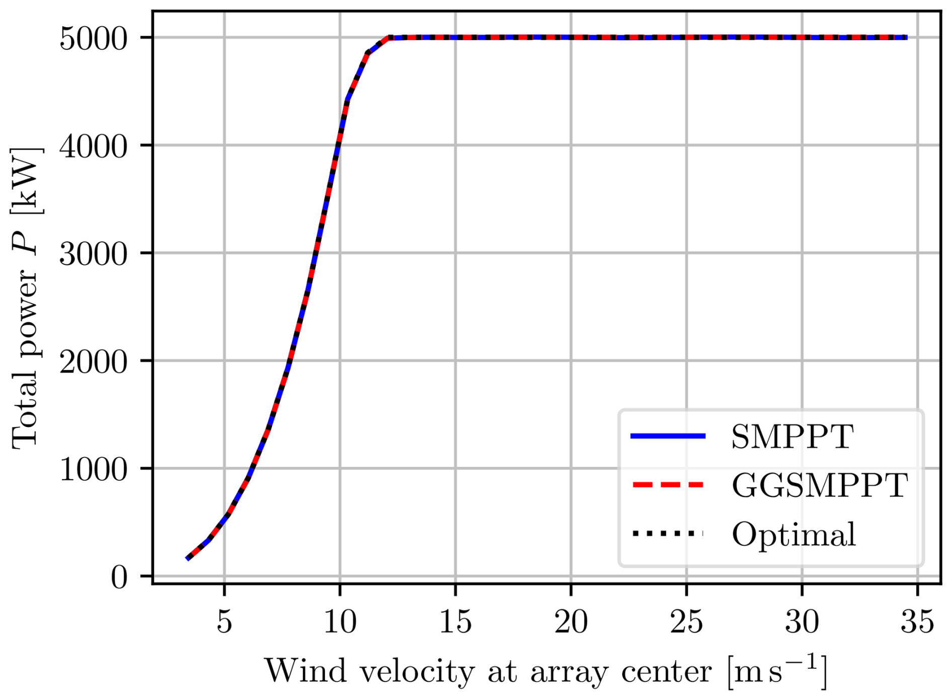
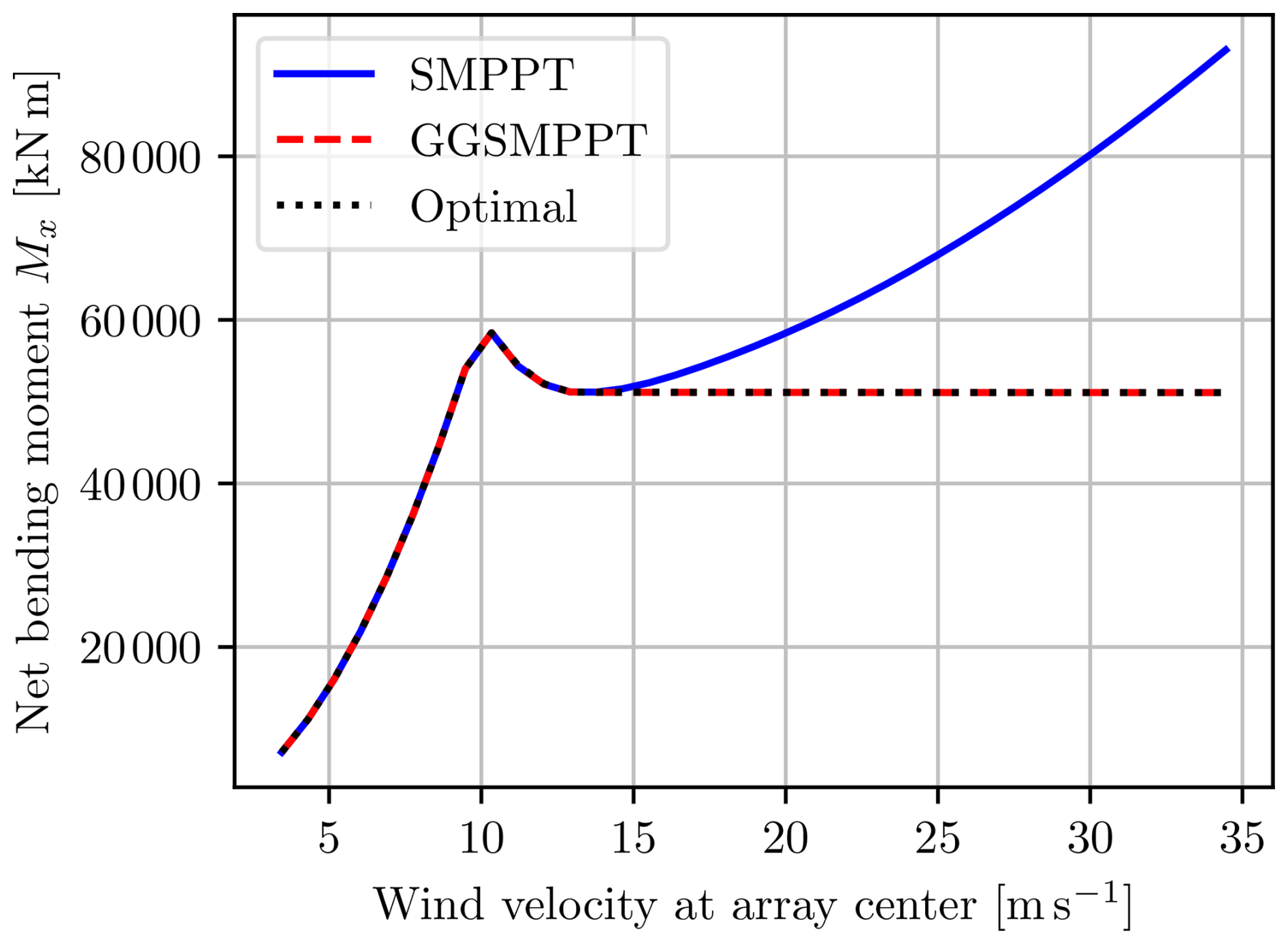
The yaw misalignment for the three control algorithms at steady state is shown in Fig. 31, and the corresponding power output is shown in Fig. 32. It is clear that all three algorithms perform identically in terms of power, but only the GGSMPPT algorithm approximates the optimal furling angle. One of the consequences of this is the difference in bending moments shown in Fig. 33. Both the numerically optimal solution and the GGSMPPT algorithms have the same constant bending moment at high freestream wind velocities, while the SMPPT bending moment keeps increasing with wind speed because the multi-rotor remains aligned with the wind. These results show that furling could be a viable alternative to pitch control in multi-rotor systems and that the control system for such a design could be both computationally efficient and almost optimal by implementing the GGSMPPT controller.

The work presented here has been simplified under the stated assumptions, so it is not to be regarded as a complete analysis of the system. An effect mentioned in Muljadi et al. (1998), which has not been included here, considers the yaw moment generated on a single rotor when furling, in addition to the increase in flap loads and possibly increased noise. However, the smaller, potentially more rigid multi-rotor blades might not be influenced as much by these effects as large rotor blades. Other aspects, such as how the furling will be performed and its effects on the system, have also not been investigated. Traditionally, furling has often been implemented with mechanical devices or actuators, as discussed in Chirca et al. (2020), but these wear out over time. Using differential thrusting, one could potentially eliminate these issues, possibly at the cost of reducing overall power production slightly.
This paper presents a novel steady-state multi-rotor wind turbine model and the high-level control strategies presented in Matras (2025). The novelty of the model stems from the inclusion of an admittedly somewhat simplified version of the aerodynamic interactions between the rotors. These interactions predict some interesting phenomena for multi-rotor wind turbines, which, as shown, can be leveraged to obtain simple high-level control schemes that allow for the use of a decoupled control strategy on the single-rotor level. The solution to the complex optimization problem involving numerous rotors and states can thus be approximated by an almost trivial algorithm.
These intriguing results raise many new questions and engineering challenges. The most fundamental area for future work perhaps involves the validation of the multi-rotor interaction effect and increasing the model's fidelity to further investigate the topic of furling. An investigation of furling and how this effect is best achieved naturally follows, as well as dynamic considerations to establish stability and a baseline for control algorithms. Other consequences of furling, such as support structure and blade designs, would also benefit from scientific attention.
The code used in this study is not publicly available. However, all information required to reproduce the presented results is given in this article or in the corresponding references. Specific code portions can be provided upon reasonable request.
The data used have been referenced and can be found directly in the cited studies (e.g., Jonkman et al., 2009).
MDP developed the models in collaboration with FM, who also implemented, simulated and described the results and wrote the paper, including the creation of all figures. MDP contributed as a supervisor during the whole process.
The contact author has declared that neither of the authors has any competing interests.
Publisher’s note: Copernicus Publications remains neutral with regard to jurisdictional claims made in the text, published maps, institutional affiliations, or any other geographical representation in this paper. While Copernicus Publications makes every effort to include appropriate place names, the final responsibility lies with the authors.
This paper was edited by Maurizio Collu and reviewed by two anonymous referees.
Abdullah, M., Yatim, A., Tan, C., and Saidur, R.: A review of maximum power point tracking algorithms for wind energy systems, Renew. Sustain. Energ. Rev., 16, 3220–3227, https://doi.org/10.1016/j.rser.2012.02.016, 2012. a
Apata, O. and Oyedokun, D.: An overview of control techniques for wind turbine systems, Scientific African, 10, e00566, https://doi.org/10.1016/j.sciaf.2020.e00566, 2020. a
Barzegar-Kalashani, M., Seyedmahmoudian, M., Mekhilef, S., Stojcevski, A., and Horan, B.: Small-scale wind turbine control in high-speed wind conditions: A review, Sustainable Energy Technologies and Assessments, 60, 103577, https://doi.org/10.1016/j.seta.2023.103577, 2023. a, b
Bezanson, J., Edelman, A., Karpinski, S., and Shah, V. B.: Julia: A fresh approach to numerical computing, SIAM Rev., 59, 65–98, https://doi.org/10.1137/141000671, 2017. a, b
Chirca, M., Dranca, M., Oprea, C. A., Teodosescu, P.-D., Pacuraru, A. M., Neamtu, C., and Breban, S.: Electronically Controlled Actuators for a Micro Wind Turbine Furling Mechanism, Energies, 13, 4207, https://doi.org/10.3390/en13164207, 2020. a
Dalala, Z. M., Zahid, Z. U., and Lai, J.-S.: New Overall Control Strategy for Small-Scale WECS in MPPT and Stall Regions With Mode Transfer Control, IEEE T. Energy Conver., 28, 1082–1092, https://doi.org/10.1109/TEC.2013.2287212, 2013. a, b
Dunning, I., Huchette, J., and Lubin, M.: JuMP: A Modeling Language for Mathematical Optimization, SIAM Rev., 59, 295–320, https://doi.org/10.1137/15M1020575, 2017. a
Muljadi, E., Forsyth, T., and Butterfield, C. P.: Soft-Stall Control versus Furling Control for Small Wind Turbine Power Regulation, windpower '98, 27 April–1 May 1998, https://digital.library.unt.edu/ark:/67531/metadc867645/ (last access: 12 May 2025), 1998. a
Guenoune, I., Plestan, F., and Chermitti, A.: Control of a new structure of twin wind turbine, in: 2016 IEEE International Conference on Renewable Energy Research and Applications (ICRERA), Birmingham, UK, 20–23 November 2016, 490–495, https://doi.org/10.1109/ICRERA.2016.7884385, 2016. a
Innes, M.: Flux: Elegant Machine Learning with Julia, Journal of Open Source Software, 3, 602, https://doi.org/10.21105/joss.00602, 2018. a
Innes, M., Saba, E., Fischer, K., Gandhi, D., Rudilosso, M. C., Joy, N. M., Karmali, T., Pal, A., and Shah, V.: Fashionable Modelling with Flux, CoRR, abs/1811.01457, arxiv [preprint], https://doi.org/10.48550/arXiv.1811.01457, 2018. a
Jamieson, P.: Innovation in wind turbine design, Wiley, Chichester, West Sussex, Hoboken, N.J, 1st edn., ISBN 978-0-470-69981-2, 2011. a
Jamieson, P. and Branney, M.: Structural Considerations of a 20MW Multi-Rotor Wind Energy System, J. Phys. Conf. Ser., 555, 012013, https://doi.org/10.1088/1742-6596/555/1/012013, 2014. a
Joglekar, M. and Loewy, R.: An Actuator-disc analysis of helicopter wake geometry and the corresponding blade response, USAAVLABS Technical Report 96–66, U.S. ARMY Air Mobility Research and Development Laboratory, 1970. a
Johnson, K., Pao, L., Balas, M., and Fingersh, L.: Control of variable-speed wind turbines: Standard and adaptive techniques for maximizing energy capture, Control Systems, IEEE, 26, 70–81, https://doi.org/10.1109/MCS.2006.1636311, 2006. a
Johnson, W.: Helicopter Theory, Dover Books on Aeronautical Engineering Series, Dover Publications, ISBN 9780486682303, https://books.google.cv/books?id=SgZheyNeXJIC (last access: 12 May 2025), 1994. a
Jonkman, J., Butterfield, S., Musial, W., and Scott, G.: Definition of a 5 MW Reference Wind Turbine for Offshore System Development, Tech. rep., National Renewable Energy Laboratory (NREL), https://doi.org/10.2172/947422, 2009. a, b, c
MacMahon, E. and Leithead, W.: Performance Comparison of Optimised and Non-Optimised Yaw Control for a Multi Rotor System, in: 2018 IEEE Conference on Control Technology and Applications (CCTA), IEEE, Copenhagen, 1638–1643, ISBN 978-1-5386-7698-1, https://doi.org/10.1109/CCTA.2018.8511353, 2018. a
Manwell, J. F., McGowan, J. G., and Rogers, A. L.: Wind Energy Explained: Theory, Design and Application, Wiley, Chichester, UK, 2nd edn., ISBN 9780470015001, 2010. a, b
Matras, F.: Modeling, Simulation and Control of Multirotor Systems, PhD thesis, Norwegian University of Science and Technology, ISBN 978-82-326-8665-0, 2025. a, b, c
Matras, F. and Pedersen, M. D.: On the Necessity of Dynamic Inflow, Modeling, Identification and Control, 45, 29–39, https://doi.org/10.4173/mic.2024.1.3, 2024. a, b
Matras, F., Reinhardt, D. P., Gryte, K., and Dinhoff Pedersen, M.: Homogeneous Parametric Modeling of Airloads, System Theory, Control and Computing Journal, 3, 1–11, https://stccj.ucv.ro/index.php/stccj/article/view/44/33 (last access: 12 May 2025), 2023. a, b, c, d
Matras, F., Årsandøy, F. X. N., and Pedersen, M. D.: Modeling, Analysis and Optimization of Multirotor Power Consumption, in: 2024 10th International Conference on Control, Decision and Information Technologies (CoDIT), Valletta, Malta, 1–4 July 2024, 2680–2685, https://doi.org/10.1109/CoDIT62066.2024.10708188, 2024. a, b, c, d
McTavish, S., Rodrigue, S., Feszty, D., and Nitzsche, F.: An investigation of in-field blockage effects in closely spaced lateral wind farm configurations, Wind Energy, 18, 1989–2011, https://doi.org/10.1002/we.1806, 2015. a
Myriad Wind Energy Systems: Developing modular wind energy for a more affordable and sustainable future, https://www.myriadwind.com/ (last access: 9 May 2025), 2024. a
Sandhu, N.: Performance and Economic Analysis of Multi-Rotor Wind Turbine, EMITTER International Journal of Engineering Technology, 6, 289, https://doi.org/10.24003/emitter.v6i2.298, 2018. a
Schlichting, H. and Shapiro, A. H.: Boundary Layer Theory, Sixth Edition, J. Appl. Mech., 35, 846–846, https://doi.org/10.1115/1.3601336, 1968. a
Skogestad, S. and Postlethwaite, I.: Multivariable feedback control: analysis and design, Wiley, ISBN 0-470-01167-X, 2005. a, b, c
Spagnolo, F., Papageorgiou, D., Galeazzi, R., Thomsen, J. S., and Sørensen, K. H.: Extremum Seeking Control for Multi-Rotor Wind Turbine in the Full-Load Region, IFAC PapersOnLine, 53, 5386–5391, https://doi.org/10.1016/j.ifacol.2020.12.1525, 2020. a
Sørensen, K. H., Knudsen, T., Filsoof, O. T., Hovgaard, T. G., Grunnet, J. D., Neto, J. X. V., and Wisniewski, R.: Multi-Rotor Wind Turbine Control Challenge – A Benchmark for Advanced Control Development, in: 2018 IEEE Conference on Control Technology and Applications (CCTA), IEEE, Copenhagen, Denmark, 21–24 August 2018, 1615–1622, ISBN 978-1-5386-7698-1, https://doi.org/10.1109/CCTA.2018.8511511, 2018. a
van der Laan, M. P., Andersen, S. J., Ramos García, N., Angelou, N., Pirrung, G. R., Ott, S., Sjöholm, M., Sørensen, K. H., Vianna Neto, J. X., Kelly, M., Mikkelsen, T. K., and Larsen, G. C.: Power curve and wake analyses of the Vestas multi-rotor demonstrator, Wind Energ. Sci., 4, 251–271, https://doi.org/10.5194/wes-4-251-2019, 2019. a
Wächter, A. and Biegler, L. T.: On the implementation of an interior-point filter line-search algorithm for large-scale nonlinear programming, Math. Program., 106, 25–57, 2006. a
Wind Catching Systems AS: Designed for floating wind, https://windcatching.com/ (last access: 9 May 2025), 2021. a
Zhuang, J., Tang, T., Ding, Y., Tatikonda, S., Dvornek, N., Papademetris, X., and Duncan, J. S.: AdaBelief Optimizer: Adapting Stepsizes by the Belief in Observed Gradients, in: Advances in Neural Information Processing Systems, edited by: Larochelle, H., Ranzato, M., Hadsell, R., Balcan, M. F., and Lin, H., Curran Associates, Inc., 33, 18795–18806 https://proceedings.neurips.cc/paper_files/paper/2020/file/d9d4f495e875a2e075a1a4a6e1b9770f-Paper.pdf (last access 9 May 2025), 2020. a