the Creative Commons Attribution 4.0 License.
the Creative Commons Attribution 4.0 License.
 | 24 Feb 2026
Phase controlling the yaw motion of floating wind turbines with the helix method to reduce wake interactions: an experimental investigation
Daniel van den Berg
Daan van der Hoek
Delphine De Tavernier
Jonas Gutknecht
Jan-Willem van Wingerden
The wake interaction between wind turbines causes significant losses in wind farm efficiency that can potentially be alleviated using wake control techniques. We provide detailed experimental evidence on how the coupling between the so-called helix wake control technique and a floating turbine's yaw dynamics can be used to increase wake recovery. Using tomographic particle image velocimetry during wind tunnel experiments, we analysed the wake dynamics and its coupling to a floating wind turbine. The measurements show that ensuring the floating turbine's yaw motion is in phase with the blade pitch dynamics of the helix technique enables an increase of 12 percentage points in available energy in the flow on top of the helix method applied to bottom-fixed turbines. We find that the in-phase scenario results in an earlier interaction between the tip and hub vortices inside the wake, which leads to the desired breakdown of the vortices, thus accelerating the entrainment of energy into the wake.
- Article
(8931 KB) - Full-text XML
- BibTeX
- EndNote


Wind energy plays a key role in efforts to decarbonise global energy production. For example, the European Commission aims to increase its offshore wind production from 38 GW today to 450 GW by 2050 in order to meet 30 % of Europe’s electricity demand at that time (Costanzo et al., 2022). Meeting this target requires a major expansion of the wind energy production capacity at offshore locations, where the majority of Europe's wind energy resources can be found (Fraile et al., 2021). However, 60 % of these energy resources are located in waters too deep for conventional bottom-fixed wind turbines to be economically feasible (Fraile et al., 2021). It is therefore expected that floating wind turbines will be deployed in wind farms of similar sizes to those currently seen with bottom-fixed turbines (WindEurope, 2023). Although individual turbines are capable of operating close to their theoretical maximum efficiency, a wind farm can experience an efficiency drop of up to 40 % due to the interaction between wind turbines (Bastankhah and Porté-Agel, 2016; Howland et al., 2019; Barthelmie et al., 2010).
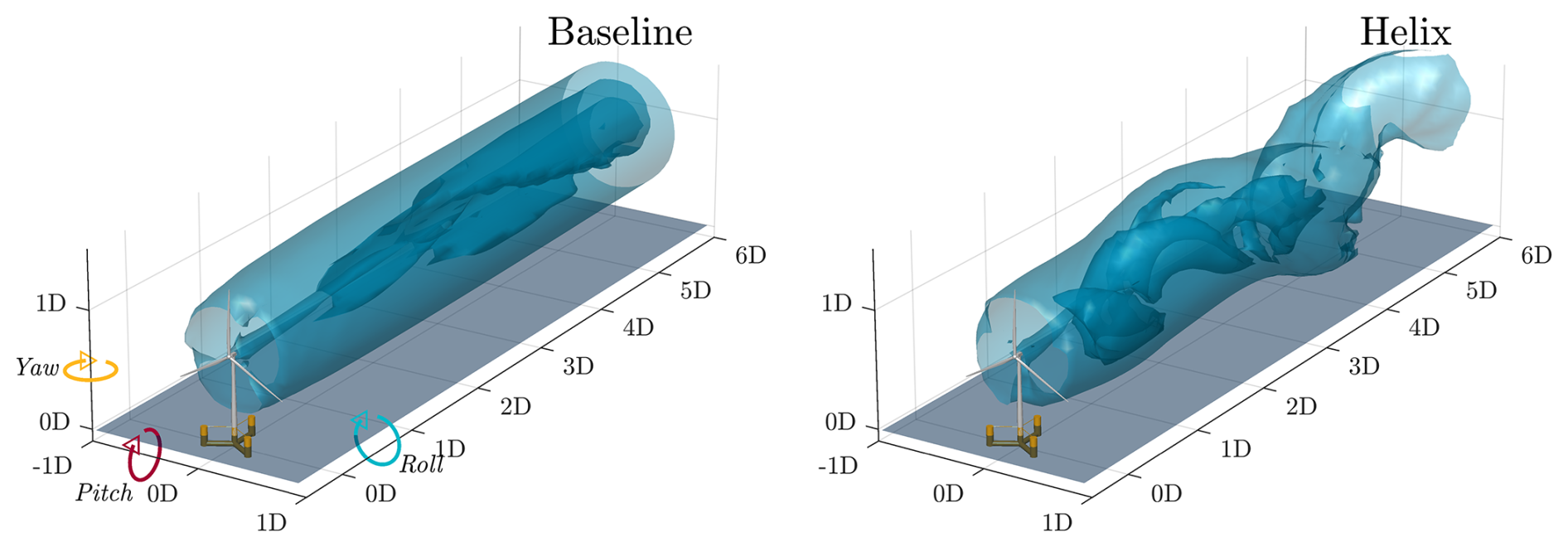
Figure 1Model of the IEA 15 MW turbine mounted on the VolturnUS-S floater, with the left figure showing the wake when using a baseline controller and the right figure the distorted wake when the helix method is enabled. The visualised wakes feature isosurfaces of the streamwise velocity taken from large-eddy simulation results by Frederik et al. (2020b).
As a wind turbine extracts energy from the incoming airflow, it leaves a wake of lower velocity and more turbulent airflow. To mitigate turbine-to-turbine wake interaction, methods such as wake steering (Fleming et al., 2017; Becker et al., 2022; Howland et al., 2022; Stanley et al., 2023), static induction control (van der Hoek et al., 2019; Bossanyi et al., 2022), and dynamic blade pitch control (Goit and Meyers, 2015; Frederik et al., 2020a) have been developed. With some exceptions (e.g. Kheirabadi and Nagamune, 2020), the development of control approaches to mitigate wake interactions has so far focused mostly on bottom-fixed wind farms (Meyers et al., 2022; Houck, 2022). When implementing controllers designed for bottom-fixed turbines on floating turbines, the coupling to the dynamics from the additional 6 degrees of freedom can significantly affect controller performance (Veen et al., 2012; Stockhouse et al., 2023; Lozon et al., 2024). Furthermore, research into the impact of certain specific (floating) turbine movements on wake stability has garnered increasing interest, with results indicating that these can enhance wake mixing (Wei et al., 2024; Fontanella et al., 2025; Messmer et al., 2025). Recent studies (van den Berg et al., 2022, 2023, 2024b) have revealed that collective and individual pitch control techniques can excite the motion of a floating turbine. The magnitude of the motion is dependent on the excitation frequency of the wake-mixing technique and its coupling to the floating turbine dynamics. In the case of collective pitch control, the time-varying magnitude of the thrust force creates a fore–aft motion of the turbine rotor. The coupling between the blade pitch input and this motion was found to reduce the effectiveness of the wake-mixing technique, leading to reduced wake recovery (van den Berg et al., 2023; van den Broek et al., 2023).
In this work, we focus on dynamic individual pitch control, often referred to as the helix method (Frederik et al., 2020b; Doekemeijer et al., 2024). The helix method is a wake-mixing method whereby the turbine blades are pitched such that a helical structure of low wind speed is created in the wake behind the turbine. When applied at the right frequency, wake recovery is significantly accelerated when using the helix method (van der Hoek et al., 2024). The difference between the wake of an unactuated and actuated turbine can be seen in Fig. 1, which shows two wakes behind the IEA 15 MW turbine (Gaertner et al., 2020) mounted on the VolturnUS-S foundation (Allen et al., 2020).
When the helix method is applied, the thrust vector of a turbine receives an offset that moves over the rotor plane in a circular fashion (Gutknecht et al., 2025a). The resulting tilt and yaw moments can instigate motions of the floating turbine. This interaction was first investigated in van den Berg et al. (2022), where it was found that floating turbines mounted on a semi-submersible foundation, like the VolturnUS-S, have a natural frequency in the yaw motion near the actuation frequency of the helix method. Applying the helix method on such a floating turbine results in the platform starting to yaw dynamically. Dynamic yaw control is also a wake-mixing control method, and when applied with the right frequency and amplitude, it can improve wind farm power yield (Lin and Porté-Agel, 2024; Mühle et al., 2024a). A combination of these two methods (i.e. the helix method and dynamic yaw) could potentially further enhance wake recovery.
A feature of an eigenfrequency is that the phase shift between the input and output signal drops by 180°. This is shown in Fig. 2, which is a frequency response diagram of the three angular motions of the floating turbine when subjected to a yaw moment input from the helix method. The top graph denotes the gain, i.e. by how much the input signal is multiplied into the output. The bottom graph denotes the phase shift between the input signal and specific angular motion. The green-shaded area denotes the frequency range in which the helix method is found to be effective and is typically characterised by the Strouhal number
where fe is the actuation frequency in hertz, D is the rotor diameter in metres, and U∞ is the freestream wind speed in metres per second. With the helix method, fe refers to the frequency at which the thrust vector circles the rotor plane. To achieve this, the blades have to pitch at a much faster rate, more specifically , with blade pitch frequency fβ and rotor frequency fr. The frequency at which the helix is most effective is found to be consistent for different-sized turbines and lies between St=0.20 and St=0.40 when considering two fully aligned turbines spaced a distance of 5 rotor diameters (often referred to as “5D”) apart (Frederik et al., 2020b; Coquelet, 2022; van der Hoek et al., 2024; Mühle et al., 2024b).
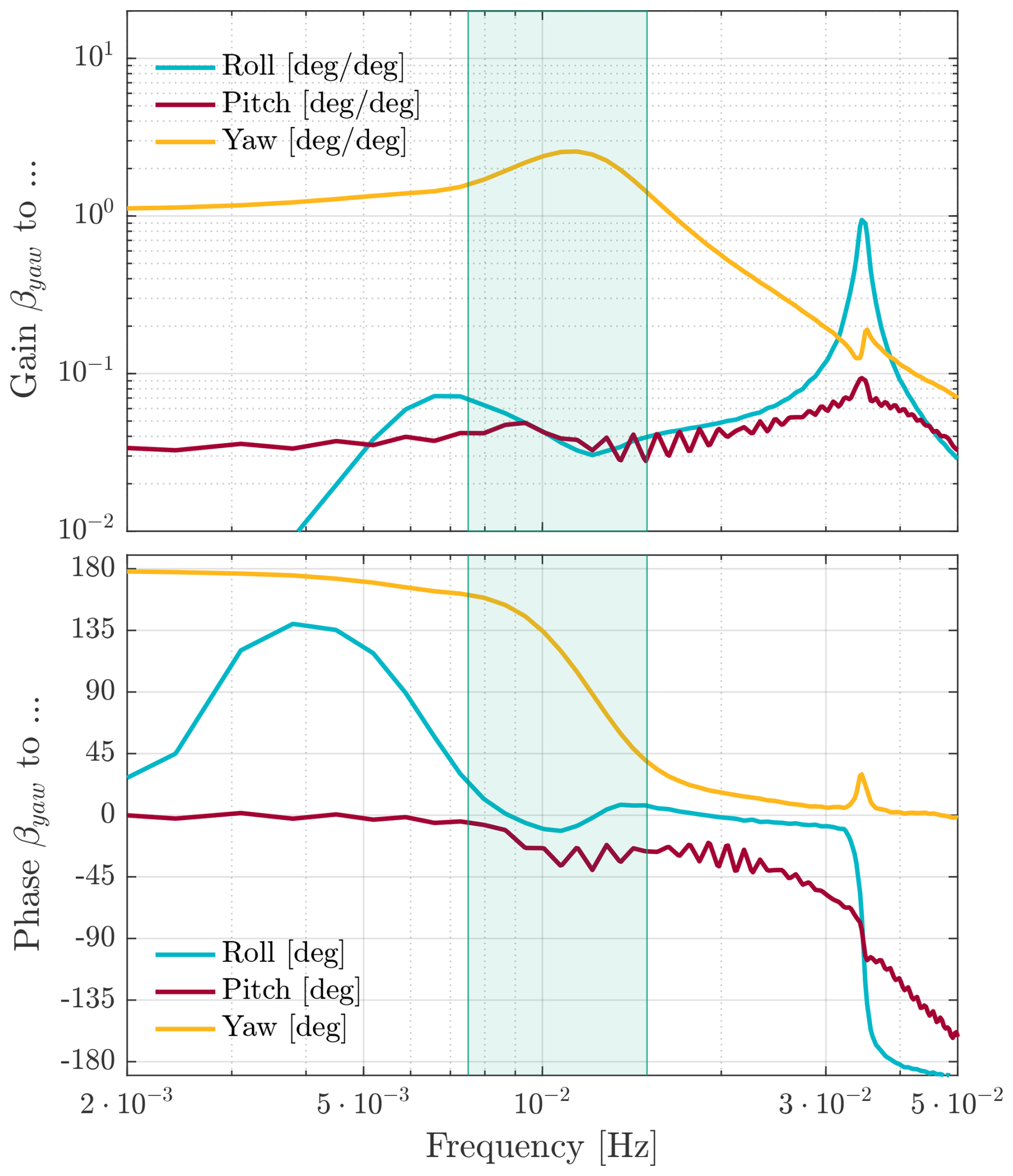
Figure 2Turbine platform's roll (blue line), pitch (red line), and yaw (yellow line) are characterised by their magnitude (top) and phase shift (bottom) with respect to blade pitch input, as a function of helix excitation frequency. The green-shaded area indicates the frequency range . The figure was created from simulation data (QBlade) run by van den Berg et al. (2024b) of the IEA 15 MW turbine on the VolturnUS platform with a uniform wind speed of U∞ = 9 m s−1.
The results presented in Fig. 2 were obtained through identification experiments by van den Berg et al. (2024b) using a full-scale floating turbine (IEA 15 MW on the VolturnUS platform) and QBlade as a simulation suite (Marten, 2020). For this experiment, the inflow was set to be uniform and constant at 9 m s−1. The wave conditions were chosen such that they correspond to calm weather at that wind speed. At its eigenfrequency of approximately St=0.30, every degree of blade pitch results in an approximately 2.5° yaw angle offset with respect to the incoming wind. On the other hand, the platform pitch and roll motion are barely excited by the yaw moment. A typical 4° blade pitch angle input would therefore lead to turbine yaw angles similar to those used for wake steering and in dynamic yaw experiments. However, due to this specific interaction (at this eigenfrequency) between the helix method and the floating turbine platform, a small change in actuation frequency close to its eigenfrequency greatly affects the phase offset between the yaw moment from the helix and the yaw motion, which impacts the wake-mixing performance.
Performance gains were observed in van den Berg et al. (2022) for downstream turbines when a floating turbine dynamically yawed as a result of applying the helix method. Power increases of up to 50 % were seen for downstream turbines when compared to the helix method without dynamic yaw. Moreover, at a certain phase offset between the helix input and yaw motion, this gain was measurably higher than for other phase offsets. This result was further investigated in van den Berg et al. (2024a), where a gain was found when both dynamic yaw and the helix method were active at certain phase offsets. Although the application of the helix method and the resulting movement introduce small efficiency losses to the upstream turbine (i.e. power losses associated with the helix method are generally in the range of 1 %–3 %; Taschner et al., 2023), van den Berg et al. (2024a) found that the power generation of a two-turbine wind farm can increase by up to 8 % when the floating turbine yaws with the helix method applied. Finally, wind tunnel experiments conducted with a porous disc that mimics the helix behaviour, which was also able to yaw dynamically, found that the helix method can be enhanced when dynamic yaw is present at the right phase offset (Gutknecht et al., 2025b).
The phase offset, or phase shift, between the helix input signal and the yaw motion of the (floating) turbine has an impact on the wake-mixing effectiveness. The tilt and yaw moments exerted by the helix can be pictured by a sine wave and a cosine wave, with the tilt moment always leading the yaw moment by 90°. When the cosine wave reaches its positive maximum, there will be no tilt moment contribution from the helix, and thus the thrust vector will only have a horizontal offset with respect to the nacelle. We now consider letting the yaw motion of the floating platform follow the cosine wave of the yaw moment (i.e. the yaw motion is in phase with the helix method). The yaw moment created by the helix method will then be strengthened by the contribution of the yawed rotor. When the yaw motion is fully out of phase (± 180°), this would still result in a fully yawed turbine, but now its yaw moment contribution opposes that of the helix method.
The goal of this paper is to validate the performance gain found in high-fidelity simulations due to the interaction between the helix method and induced yaw motions (dynamic yaw). More specifically, this work presents two main contributions investigating this interaction: (1) we describe an experimental setup to study the three-dimensional wake aerodynamics behind a floating turbine that is excited in the platform yaw degree of freedom, and (2) we show that a change in phase shift between a floating turbine's yaw motion and the helix method can lead to a reduction or improvement in wake-mixing effectiveness of the helix method.
In this section, the mathematical background behind the helix method is introduced, followed by a detailed description of the wind tunnel experiments. The wind tunnel experiments combine a hardware-in-the-loop setup with tomographic particle image velocimetry (PIV) to measure the effect of the helix method and yaw motion on the wake. The floating turbine is represented by a scaled turbine (Schottler et al., 2016), which is capable of applying the helix method, mounted on a hexapod. The yaw motion is imposed on the hexapod, with the motion being representative of an actual floating turbine applying the helix method according to the dynamics shown in Fig. 2. The pitch and roll motions of the platform are not considered, as Fig. 2 shows that these motions are not strongly affected by the helix method. The platform motion due to waves is not reproduced for simplicity and to isolate the effect of the helix and dynamic yaw motion on wake recovery. The impact of the yaw motion at different phase offsets is quantified by analysing the wind speed in the wake. Tomographic PIV using neutrally buoyant helium-filled soap bubbles (HFSBs) is used to visualise the wake.
2.1 The helix wake-mixing method
The helix wake-mixing method is applied in an open-loop control scheme by setting sinusoidal input signals to the fixed-frame blade pitch angles. Using the multi-blade-coordinate (MBC) transformation (Bir, 2008), these are transformed into a time-varying individual blade pitch signal that is applied to the turbine:
where ψi is the azimuth angle of the blade, and βcol, βtilt, and βyaw are the fixed-frame pitch angles, with the subscript “col” referring to the mean pitch angle of all three blades. The time-varying pitch angles create time-varying out-of-plane bending moments My,i, which can be transformed back into fixed-frame moments using the inverse MBC transformation:
where Mcol, Mtilt, and Myaw are the fixed-frame moments with the subscript “col” referring to the collective moment of the turbine. With the helix method, Mtilt and Myaw are varied in a sinusoidal manner, with one signal being phase shifted by 90° with respect to the other. These moments are a direct result of the thrust vector being moved off-centre and in a circular motion over the rotor plane when the individual blades are pitched. This also leads to the characteristic helical shape in the wake when this method is applied.
2.2 Experimental setup
The experiments were carried out at the Open Jet Facility of the Delft University of Technology, which is an open-jet, closed-circuit wind tunnel with a width and height of 2.85 m. All experiments were run at a constant wind tunnel velocity of U∞ = 5 m s−1. The turbulence intensity inside the jet was within the range of 0.5 % to 2 %, which was primarily due to the presence of the PIV seeding rake that ejects the helium soap bubbles into the flow (van der Hoek et al., 2024). A modified version of the MoWiTO-0.6 turbine (Schottler et al., 2016; van der Hoek et al., 2024) with a rotor diameter of D = 0.58 m was used. These settings result in a rotor-diameter-based Reynolds number of 1.9 × 10⁵, which ensures wake similarity to full-scale turbines (Chamorro et al., 2012). The turbine rotor was placed at a safe distance from the turbulent boundary layer of the jet, as investigated in (Lignarolo et al., 2014). The blockage ratio based on the rotor-swept area and jet outlet is 3.3 %, requiring no corrections to the wake measurements (Chen and Liou, 2011). Both the turbine and the hexapod were connected to a dSpace MicroLabBox, enabling real-time control and data transferral between the turbine and hexapod at a sampling rate of f = 2 kHz. Once the hexapod was calibrated and zeroed, each of the 6 degrees of freedom could be controlled and synchronised to the blade pitch input of the wind turbine.
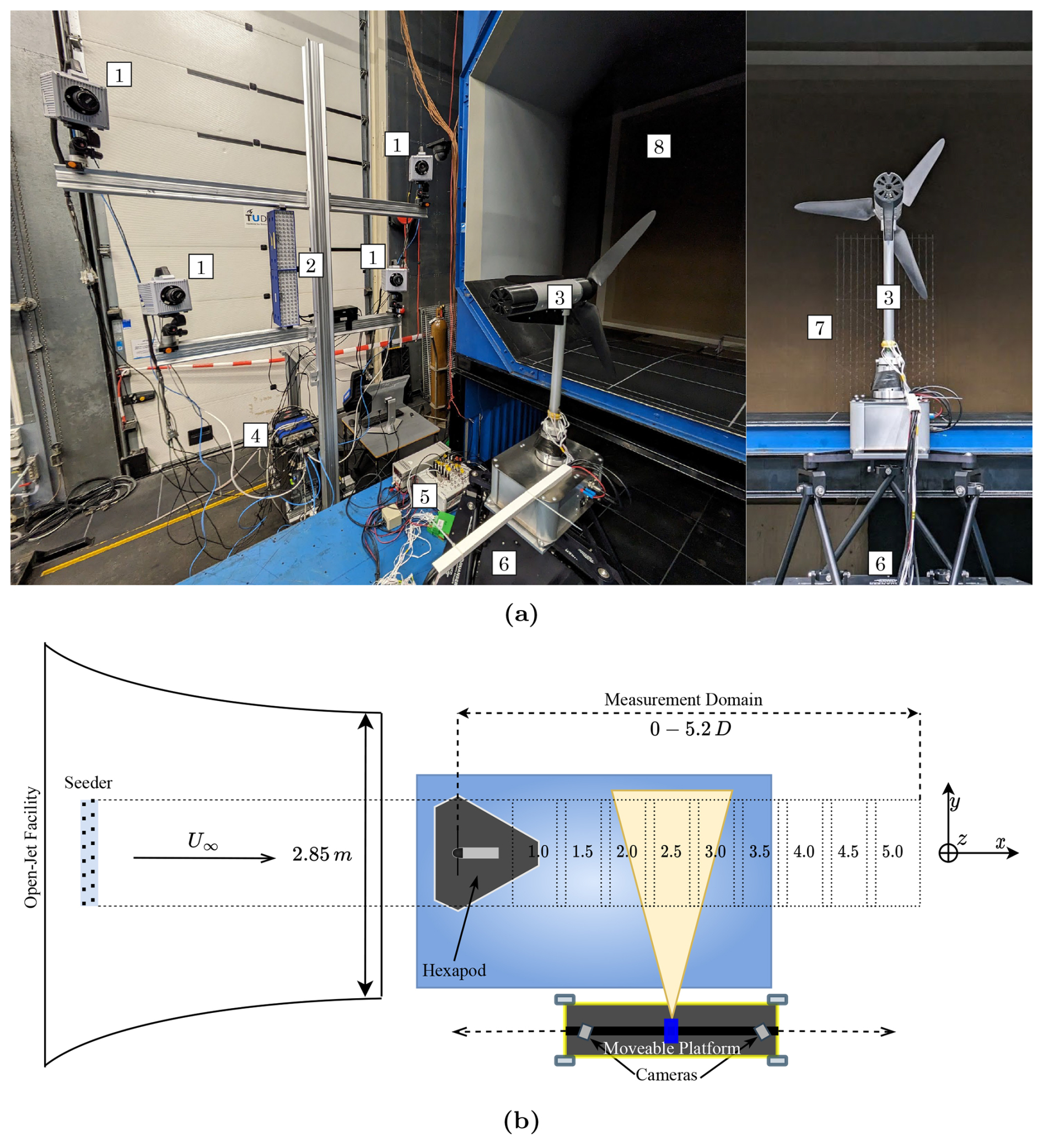
Figure 3(a) PIV setup consisting of ![]() four Photron FASTCAM SA1.1 high-speed cameras,
four Photron FASTCAM SA1.1 high-speed cameras, ![]() two LaVision LED lights used to illuminate the HFSBs,
two LaVision LED lights used to illuminate the HFSBs, ![]() the MoWiTO-0.6 turbine,
the MoWiTO-0.6 turbine, ![]() a LaVision PTU-X timing unit used to synchronise the four cameras and LEDs,
a LaVision PTU-X timing unit used to synchronise the four cameras and LEDs, ![]() a dSpace MicroLabBox used for control and data acquisition,
a dSpace MicroLabBox used for control and data acquisition, ![]() the Quansar Hexapod,
the Quansar Hexapod, ![]() the seeding rig from which the HFSBs are released into the flow, and
the seeding rig from which the HFSBs are released into the flow, and ![]() the Open Jet Facility. (b) Schematic representation of the setup. The camera setup is mounted on a multi-axis linear actuator to allow movement along the x axis. The origin of the coordinate system used in the experiment is defined at the centre of the rotor plane.
the Open Jet Facility. (b) Schematic representation of the setup. The camera setup is mounted on a multi-axis linear actuator to allow movement along the x axis. The origin of the coordinate system used in the experiment is defined at the centre of the rotor plane.
Figure 3 shows the experimental setup. The wake behind the turbine was visualised by neutrally buoyant helium-filled soap bubbles (HFSBs) (Scarano et al., 2015), which were ejected into the flow by a seeding rake with dimensions of 2 m by 1 m. The HFSBs were illuminated from the side using two LaVision LEDs, enabling the HFSBs to be used as tracers for flow reconstruction. Four Photron FASTCAM SA1.1 high-speed cameras were used to record the wake at 500 frames per second at a resolution of 1024 pixel × 1024 pixels. A multi-axis linear actuator moved the PIV setup downstream of the turbine to measure multiple sections of the wake.
For the experiments, the optimal power coefficient was determined empirically as Cp=0.20. For every experiment, the pitch angle around which the helix method was implemented corresponds to the pitch angle of the maximum power coefficient. The turbine was controlled using a PI controller on the generator torque to control rotor speed. With U∞ = 5 m s−1, we adjusted the rotor speed fr such that the optimal tip-speed ratio was achieved, with ωr being the rotor speed in radians per second. This yielded fr≈13.7 revolutions per second.
2.3 PIV data acquisition
Each PIV measurement consisted of 10 s of raw camera footage. The flow tracers were reconstructed using the Shake-The-Box algorithm (Schanz et al., 2016) with Lavision's DAVIS 10 software. On average, each frame consisted of 10 000 reconstructed particles within the measurement volume. After the particle reconstruction, a dataset for all time steps of three-dimensional particle positions and velocities was obtained. For the wake analysis, the particles were spatially averaged to a Cartesian grid over smaller sub-volumes with a Gaussian weighing function. This step entails averaging the velocity information of every particle that falls into a sub-volume and assigning those averaged velocities to that sub-volume for that time step.
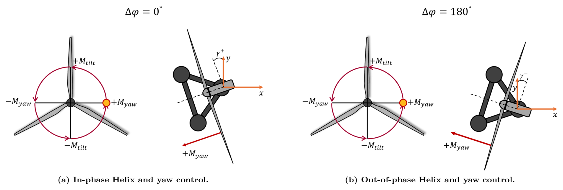
Figure 4Example illustration of the phase offset Δϕ. The location of the resultant yaw and tilt moment is visualised by the yellow circle in the rotor plane and the arrow in the top view of the turbine. When Δϕ = 0°, the turbine reaches its maximum positive yaw misalignment when the helix method induces a positive yaw moment (a). When Δϕ = 180°, the positive helix yaw moment coincides with the maximum negative yaw misalignment (b).
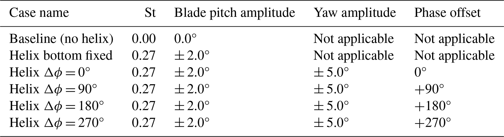
Table 1Overview of all measurement scenarios. For the cases with platform yaw motion, Δϕ denotes the phase offset.
The size of these smaller volumes determines the resolution of the reconstructed flow. Larger volumes, generally speaking, produce more consistent data at the cost of certain wake details, such as the tip vortices, which get absorbed into one large outer vortex in the averaging process. We used two cell volumes: 40 mm × 40 mm × 40 mm to analyse tip vortex behaviour and 60 mm × 60 mm × 60 mm to calculate more general wake properties such as wind speed and energy entrainment. A 75 % overlap between volumes was chosen to have smooth transitions between subsequent volumes, resulting in a grid spacing of 10 and 15 mm, respectively.
Time-averaged velocity fields were acquired by binning the particles from all time steps following the previously described averaging process. To obtain time-varying flow fields, the particles from each time step can be binned separately. However, insufficient particles in parts of the volume can result in gaps in the flow fields. By averaging the particles for specific phases based on turbine measurements, such as the rotor azimuth position ψ, the number of particles used in the binning process increases, and the measurement uncertainty is reduced.
In the case of baseline operation, the phase-averaging procedure consisted of binning the particles based on the rotor azimuth position into 12 bins of 30°. Here, we assume that the wake dynamics are sufficiently represented by 12 discrete phase bins. Subsequent averaging for each of these phase bins resulted in consecutive flow fields that show the wake over a single rotor rotation. The helix method complicates the phase-averaging procedure as the time-varying pitch actuation introduces additional dynamics to the wake that cannot be adequately captured in a single turbine rotation. Since the helix actuation can be represented by a thrust force vector moving around the rotor plane, we introduced the helix azimuth ψh as an additional phase variable for the binning process (van der Hoek et al., 2024). More specifically, the actuation frequency of St=0.27 was selected such that each helix (and yaw) cycle coincides with six rotor rotations; i.e. . Hence, the wake dynamics of the helix cases are represented by phase-averaged flow fields.
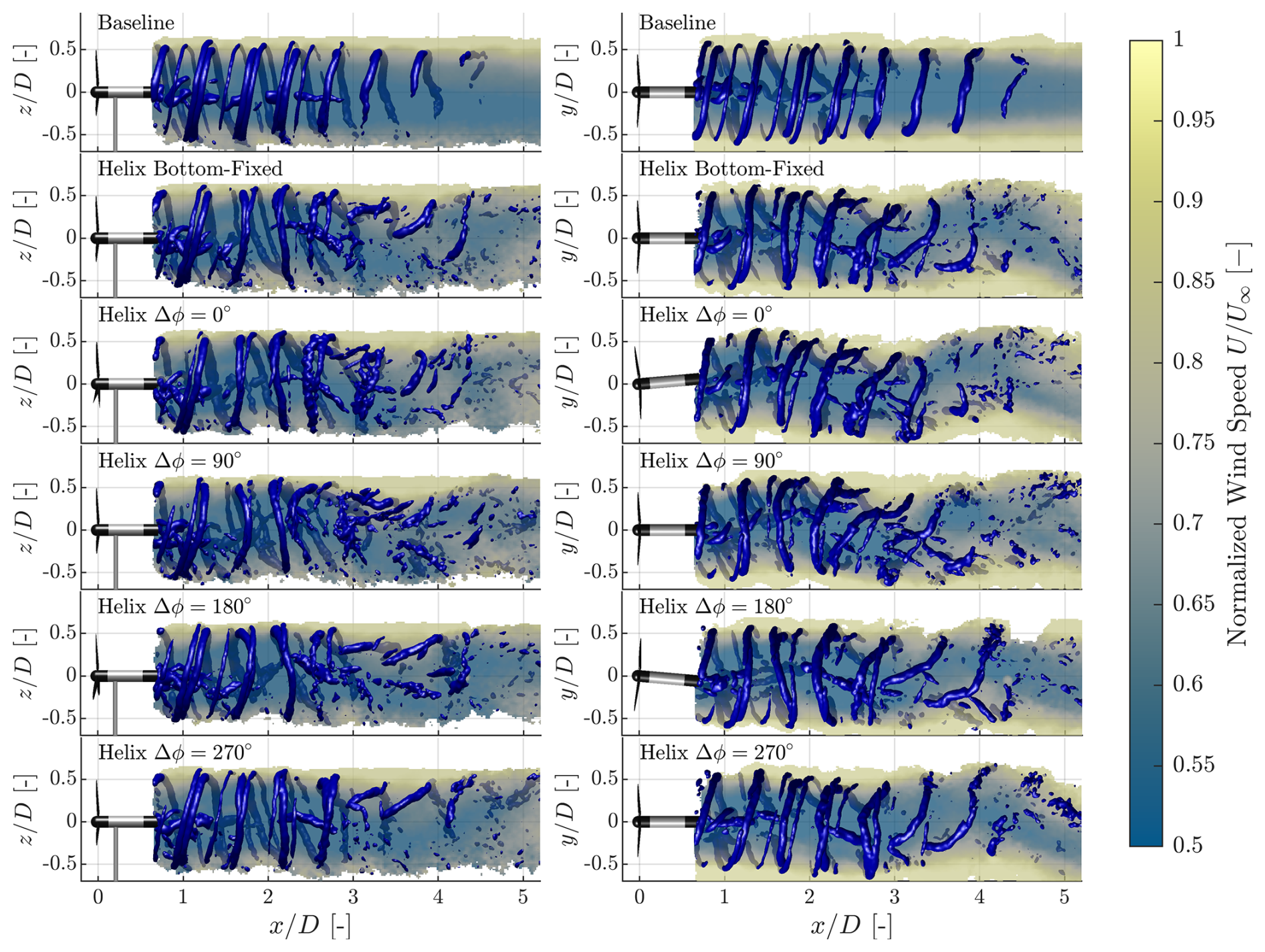
Figure 5Reconstructed side view (left column: x–z plane, y=0) and top view (right column: x–y plane, z=0) streamwise wind speed slices and Q criterion, represented by the blue isosurfaces. For all cases, the data are taken halfway through a phase-averaged cycle.
2.4 Investigated cases
In total, six different cases were investigated, of which four have different phase offsets, spaced 90° apart. The phase offset Δϕ is defined as the phase difference between the yaw moment from the helix Myaw and the yaw angle γ. The definition of this phase offset is visualised in Fig. 4 using two examples. All the cases that were investigated in the measurement campaign are summarised in Table 1. For the floating turbine that serves as the basis of this work, the phase differences can shift by 180° within the frequency range in which the helix method is effective. The effect of this is investigated by including the 0, 90, and 180° phase-offset cases. The final case with a 270° offset is added to complete the measurement and provide more insights into the interaction between dynamic yaw and the helix method. To best represent the motions a full-scale turbine would undergo, the ratio between blade pitch amplitude and yaw amplitude is based on the identified input–output relation shown in Fig. 2. The blade pitch amplitude for the helix was set to 2.0°, similar to that in van der Hoek et al. (2024). The measurement domain spans a distance of 4 rotor diameters, from 1D to 5D behind the turbine in steps of 0.5D. Each measurement spans 400 mm in the x direction and 800 mm in both the y and the z directions. Since the width of a single measurement volume is larger than 0.5D, there exists a small overlap between every measurement, which aids with post-processing. Based on these measurements, the full three-dimensional wake can be reconstructed, enabling analysis of the interaction between the yaw motion of the floating turbine and the helix wake-mixing method. Using the PIV data, wake recovery, as quantified by the wake velocity, can be analysed. Furthermore, the same PIV data can also be used to analyse the behaviour of the wake, providing insight into the aerodynamic processes that occur behind the actuated turbine. Note that for these experiments, a single actuation frequency was chosen to limit the number of individual measurements, as a single wake measurement consists of multiple PIV measurements.
In this section, the results from the experiments are shown. First, the wind speed behind the turbine is analysed, after which the energy entrainment is discussed. This is followed up by a detailed analysis of prominent wake structures and how these are affected by the change in phase offset of the yaw motion.
An example of the results obtained during the measurement campaign is shown in Fig. 5. The wind speed is shown as velocity slices in the x–z (left column) and x–y planes (right column). Prominent vortex structures in the wake, typically tip and hub vortices, are visualised using three-dimensional isosurfaces of the Q criterion (Hunt et al., 1988; Soto-Valle et al., 2022). The threshold for isosurfaces is chosen such that the relevant wake dynamics are best visualised.
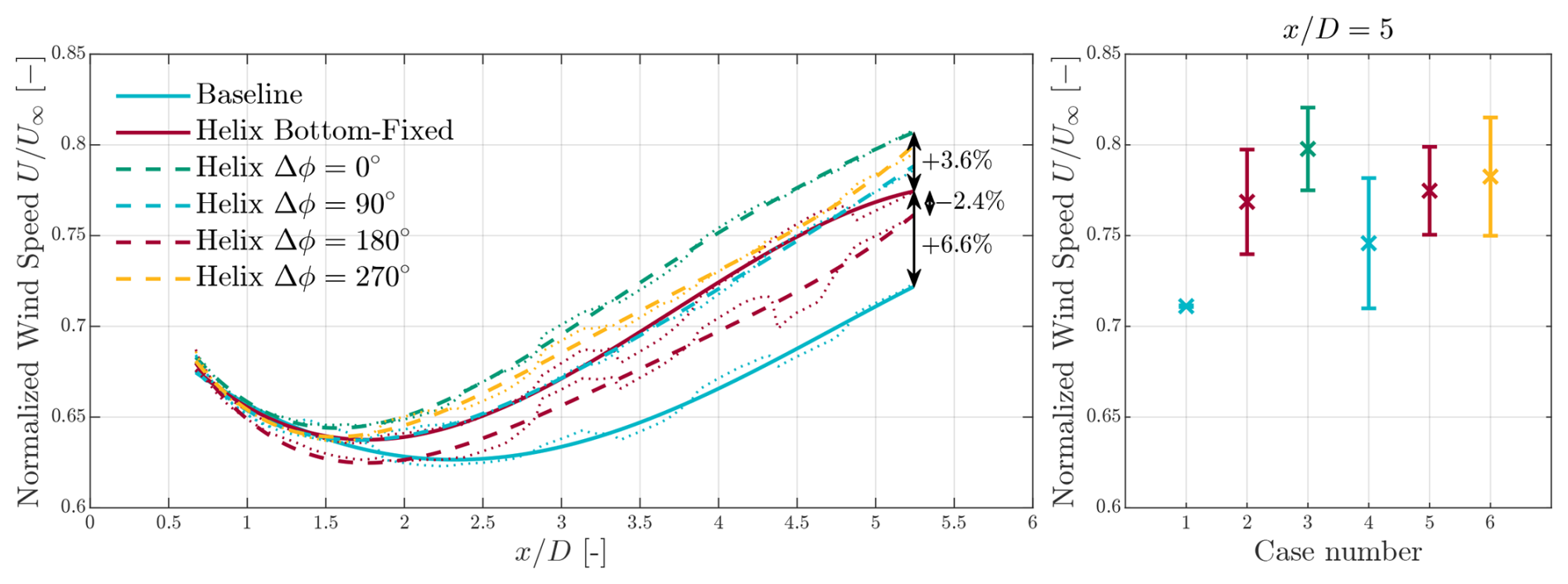
Figure 6Rotor-averaged wind speed as perceived by a hypothetical downstream turbine in the wake. The thin dotted lines show the results as measured per individual measurement domain. These data are approximated using fourth-order polynomials (thick lines), removing the jumps in data between individual measurements. The solid lines represent the results without yaw motion, and the dashed lines represent the results when the turbine is undergoing yaw motion. The right-hand side of the figure shows the mean wind speed for each case at a distance of 5D. The error bars indicate the standard deviation of the rotor-averaged wind speed over a single helix cycle.
Comparing the baseline case with any of the helix cases reveals distinct differences in wake dynamics. Where the baseline wake remains stable up to a distance of 4–4.5D from the turbine, the tip vortex structures are severely disturbed when the helix is enabled. Furthermore, the wake is also dynamically deflected due to the helix. Comparing the five helix cases, we find that when the helix input and yaw motion are in phase (Δϕ=0), wake deflection is enhanced. In contrast, when they are 180° out of phase, the deflection is reduced. In general, the structure of the tip vortices is noticeably different when the platform is yawing. If this difference in wake structure has an impact on the effectiveness of wake mixing, it can be quantified by measuring the wind speed directly behind the turbine.
Figure 6 shows the time-averaged wind speed, normalised by the inflow velocity, which a hypothetical second turbine would experience when it operates downstream of the first turbine. This is achieved by spatially averaging the time-averaged wind speed over the same area as the rotor disc. All cases show that the wake recovers as it propagates downstream, as indicated by the increasing wind speeds. The increased mixing induced by the helix method leads to an increased wind speed at the end of the domain compared to the baseline case. This gain of 6.6 percentage points () in wind speed can be equated to an increase of 21 in the power available in the flow that a downstream turbine can potentially extract. Furthermore, when the platform yaws in phase with the helix input, an additional gain of 3.6 in wind speed is achieved, which translates into an increased power gain of 12 in the flow. When the yaw motion is 180° out of phase, the gain in wind speed is reduced by 2.4 , equating to a loss of 7 in terms of extractable power in the wake compared to the wake excited by the helix method without any yaw motion.
An increase in wind speed equates to an increase in the kinetic energy of the wake. This energy is entrained from outside the wake boundary. This flux of kinetic energy is dominated by the Reynolds shear stresses (Reynolds and Hussain, 1972; Cal et al., 2010) and can be computed as
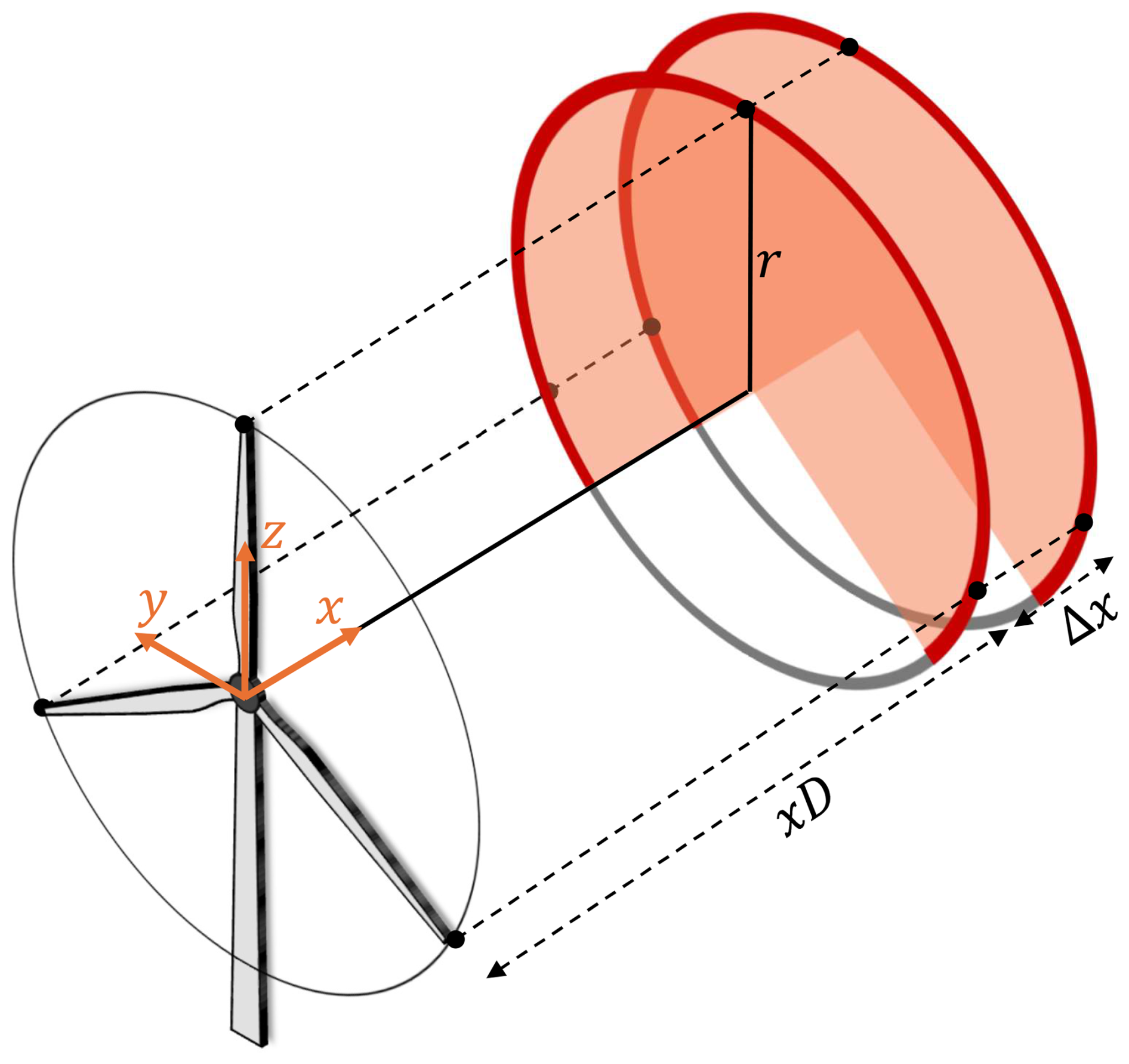
Figure 7Schematics of the entrainment calculation in the radial direction over a control volume. We consider a ring (bright red) of radius r located a distance of xD from the turbine, over which the mean flux of kinetic energy is calculated per downstream distance Δx. The Cartesian velocity components are first transformed to a cylindrical coordinate frame.
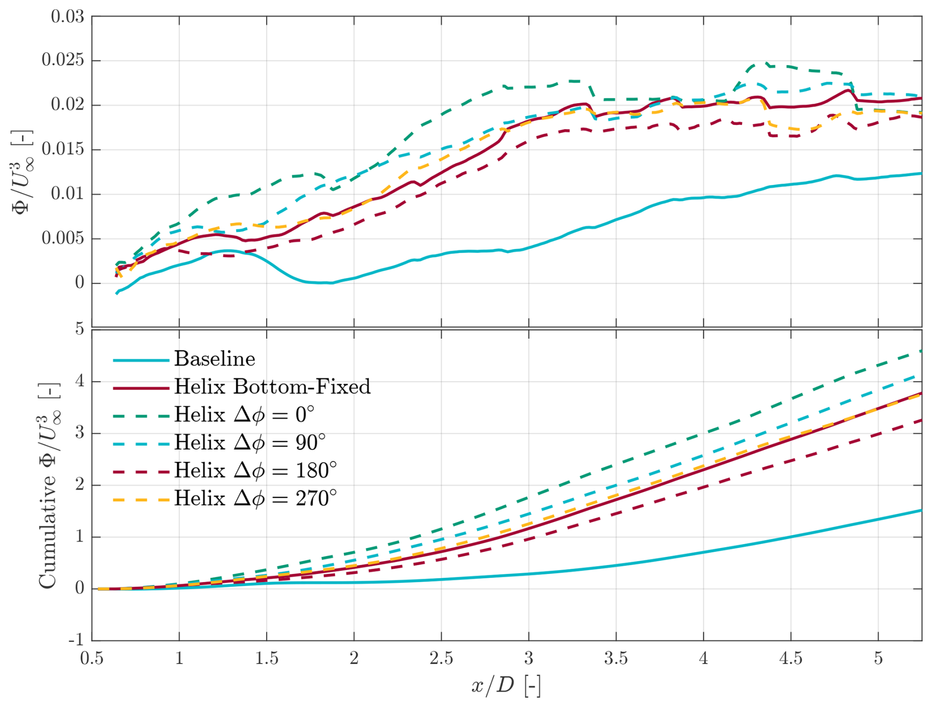
Figure 8Local (top) and cumulative (bottom) results of the energy entrainment analysis using the phase-averaged measurement data. The flux Φ has been normalised using the freestream inflow velocity U∞.
In the previous equation, represents the average streamwise velocity, and u′ and represent the velocity fluctuations around the mean in the streamwise and radial directions. The term hence gives the time-averaged Reynold's shear stress. A negative definition of the flux was used such that positive values of Φ show energy moving into the wake. A similar analysis of the wake with the helix method was done in (van der Hoek et al., 2024; Gutknecht et al., 2025a). The energy flux calculation is carried out in the radial direction over a control volume. This volume, whose boundaries are defined by the rotor surface, is schematically depicted in Fig. 7. Since the hexapod leaves a wind shadow below the wake, the bottom part of the wake (between θ = −45° and θ = 225°) is not considered for this analysis as a precaution.
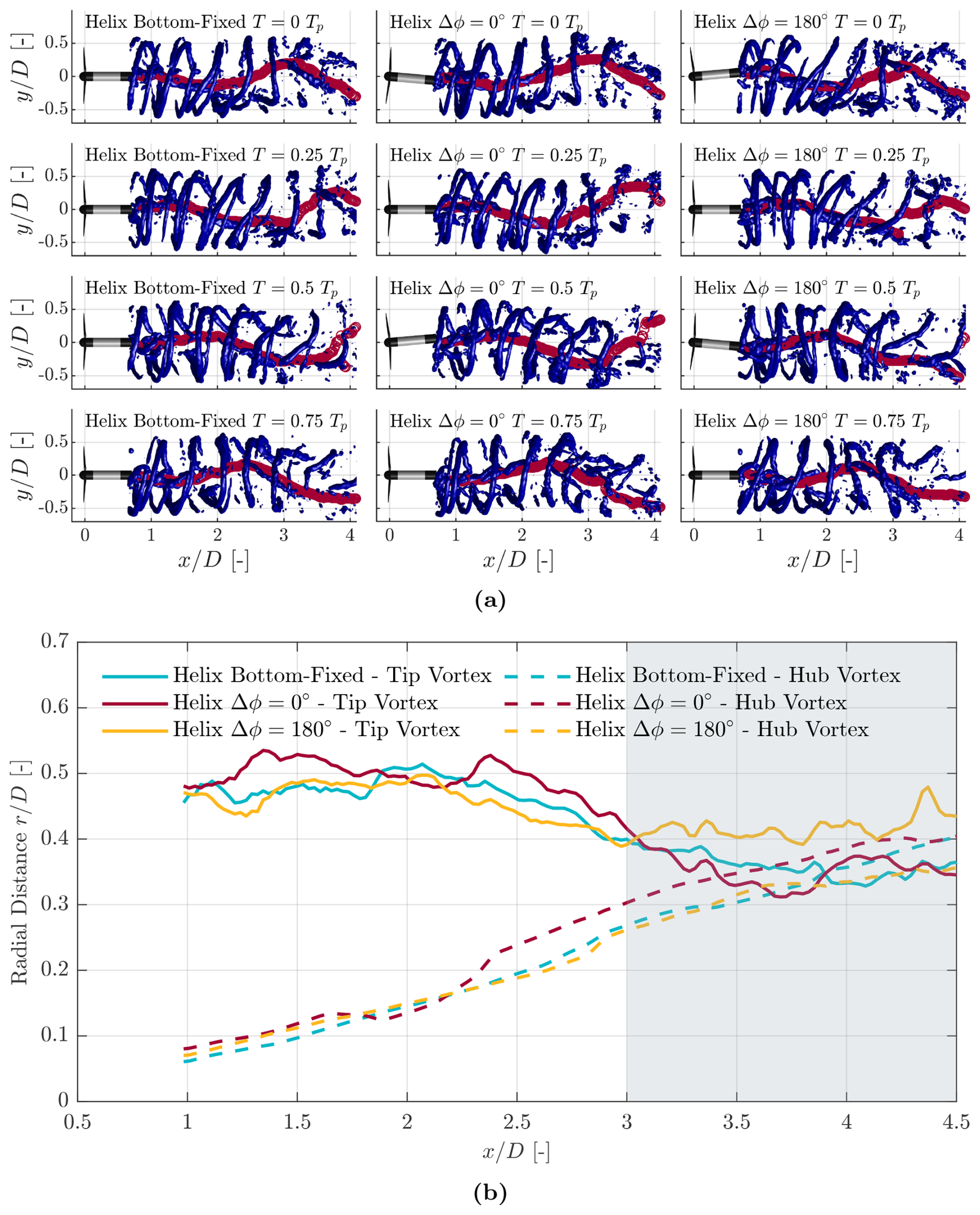
Figure 9(a) Instantaneous tip vortices and hub vortex location for the helix case (left column), the helix case with in-phase yaw motion (middle column), and the helix case with 180° out-of-phase yaw motion (right column). (b) Streamwise evolution of the averaged radial position for both tip and hub vortices with respect to the centre of the wake. The grey-shaded area indicates the area in which wake breakdown is observed in the PIV data.
Figure 8 shows the energy entrainment for the six different cases that are investigated. Analysis of the energy flux shows the same results as for the wind speed findings; i.e. when the platform yaws in phase with the helix input, entrainment is increased compared to the helix case. When the yaw motion is 180° out of phase, the opposite holds. Furthermore, after a distance of 3 rotor diameters, the energy flux becomes constant, and the differences between the individual helix cases become smaller. From Fig. 5, it can be seen that this is, on average, also the distance where the tip vortex structures start to dissolve. Hence, the gain in wind speed, due to increased entrainment, happens mainly in the area where the wake is still shielded from the ambient flow by the tip vortices and the mixing process due to random fluctuations has not fully started. The cumulative results, the total energy entrained into the wake up to that point, support the finding that the in-phase case, compared to the other cases, gains the most energy in the initial part of the wake. This head start of the in-phase case allows it to stay ahead of the other cases for the entire measured wake.
Studying the behaviour of the hub and tip vortices provides insight into the differences between the helix method and the cases where the platform yaws in phase and 180° out of phase. Figure 9 shows the tip vortices, visualised using isosurfaces of the Q criterion, and the location of the hub vortex indicated by red circles. The locations of both the tip vortices and the hub vortex are tracked over time using a Gaussian convolution method (Coudou et al., 2018; Coudou, 2021). The left column shows the helix at four different time instances T within one cycle Tp of the helix excitation. The hub vortex starts to diverge from the centre at a distance of 2D, interacting with the tip vortices at 3D. Compared to the in-phase case (middle column), this behaviour is amplified when the turbine is yawing. The wake displacement increases without altering the tip vortex structure until it begins to interact with the hub vortex. When the yawing is out of phase, the tip vortices are significantly more deformed, and the curvature introduced by the helix is reduced.
Figure 9 also shows the average radial distance for the tip and hub vortices with respect to the nacelle. As this value is calculated for exactly one cycle of the helix and then averaged, the displacement of the wake as a whole is filtered out of the measurement. As such, the differences in the radial distance, as shown in Fig. 9, stem from a difference in the interaction between the helix method and the dynamic yaw motion. For the helix case with in-phase yaw motion in particular, the tip and hub vortices approach each other the fastest, followed by the helix method and then the 180° out-of-phase yaw case. Moreover, when the hub and tip vortices are at the same radial distance, they start to interact. This accelerated interaction between the tip and hub vortices can provide an explanation for the enhanced (reduced) energy entrainment shown in Fig. 8 when the platform yaws in phase (180° out of phase) with the helix method. It should be noted that the turbine used in this study has a lower tip-speed ratio than full-scale turbines. Given that higher tip-speed ratios generally result in earlier wake recovery (Lignarolo et al., 2015), the results presented in the previous figures may differ for full-scale turbines. However, we do not expect to see any changes in the coupling behaviour of the helix method with dynamic yaw. Further research into this behaviour, using methods such as large-eddy simulations, could shed more light on the nuanced differences that occur with these interactions. What is clear from these results is that specific floating turbine dynamics can have a significant impact on aerodynamic processes that happen further in the wake and that they are coupled.
Returning to the dynamics of the floating platform in Fig. 2, we notice that not all phase offsets studied in this experiment are present. However, we can choose the actuation frequency of the helix method to obtain the most optimal phase offset for the floating platform, within the effective Strouhal range. Depending on the wind turbine model and platform type, the magnitude and phase relation of the platform motion and the helix method can differ significantly. Some platforms may offer more advantages to the helix method, whereas others may yield opposite results. By considering these effects in the floating platform design phase, we can even optimise the design for the helix method (van den Berg et al., 2024a).
The results of this study were obtained in low turbulence, with ambient turbulence intensity levels between 0.5 % and 2.0 %. Full-scale floating wind turbines will experience slightly higher levels of atmospheric turbulence. Therefore, we expect that the performance increase with the helix method, and the coupling with dynamic yaw, will be lower in such a setting. This reduction is primarily due to the enhanced wake recovery in the baseline case that is associated with increased turbulence (Korb et al., 2023).
This work demonstrates how the dynamics of a floating turbine interact with that of the helix wake-mixing method. The presence of a natural frequency in the yaw motion for certain types of foundations can lead to different phase couplings between control input and floating turbine dynamics. By experimentally analysing the three-dimensional wakes and aerodynamics of a floating turbine model, we find that actuating the helix at a frequency such that the yaw motion is in phase results in a significantly better wake recovery than when the turbine yaws 180° out of phase. Analysing the energy entrainment into the wake indicates that for the in-phase case, significantly more energy is transferred into the wake between a distance of 1 and 3 rotor diameters downstream. A significant reduction is found for the 180° out-of-phase case.
Using the volumetric PIV measurements allows us to visualise the location of the tip and hub vortices, revealing that the dynamic interaction between the two is influenced by the platform yaw motion. The earlier interaction between the tip and hub vortices leads to an earlier breakdown of the wake, accelerating the energy entrainment into the wake. When yawing at 180° out of phase, this interaction is both reduced and delayed, explaining the reduced effectiveness of the wake-mixing method. Further investigations should include analysing different phase offsets, as it could well be that the optimal offset lies between the investigated values. High-fidelity large-eddy simulations can also investigate whether the difference in phase offset will play a significant role with higher ambient turbulence. Furthermore, these simulations also enable us to examine the effect of the control methods on fatigue loads, which was not feasible in this experiment.
This work shows that the dynamics of a floating turbine can be effectively used to enhance the performance of wake-mixing controllers. These outcomes can be used to design floating turbines that optimise both control and turbine design, a process called control co-design. These optimal designs could also be extended to tackle different control challenges for floating wind turbines. For example, the pitch instability of a floating turbine manifests itself in different weather conditions to those when the helix is effective. A single, optimised controller could account for both control challenges. This will significantly contribute to the development and deployment of advanced “smart” floating wind farms.
The data used in this work are available at the 4TU repository: https://doi.org/10.4121/a8555119-db46-4ecd-9138-8785b9080ff0.v1 (van den Berg and van der Hoek, 2024).
DvdB and DvdH conceived the wind tunnel experiments presented in this work. They also performed the experiments and post-processed the data. The paper was written with contributions from JG, DDT, and JWvW, and its content was extensively discussed between all authors.
At least one of the (co-)authors is a member of the editorial board of Wind Energy Science. The peer-review process was guided by an independent editor, and the authors also have no other competing interests to declare.
Publisher's note: Copernicus Publications remains neutral with regard to jurisdictional claims made in the text, published maps, institutional affiliations, or any other geographical representation in this paper. The authors bear the ultimate responsibility for providing appropriate place names. Views expressed in the text are those of the authors and do not necessarily reflect the views of the publisher.
This project is part of the FLOATECH project and its follow-up project named FLOATFARM. The research presented in this paper has received funding from the European Union's Horizon 2020 research and innovation programme under grant agreement no. 101007142 and the European Union's Horizon programme under grant agreement no. 101136091.
This research has been supported by the EU Horizon 2020 (grant nos. 101007142 and 101136091).
This paper was edited by Johan Meyers and reviewed by two anonymous referees.
Allen, C., Viscelli, A., Dagher, H., Goupee, A., Gaertner, E., Abbas, N., Hall, M., and Barter, G.: Definition of the UMaine VolturnUS-S Reference Platform Developed for the IEA Wind 15-Megawatt Offshore Reference Wind Turbine, NREL, https://doi.org/10.2172/1660012, 2020. a
Barthelmie, R. J., Pryor, S. C., Frandsen, S. T., Hansen, K. S., Schepers, J. G., Rados, K., Schlez, W., Neubert, A., Jensen, L. E., and Neckelmann, S.: Quantifying the Impact of Wind Turbine Wakes on Power Output at Offshore Wind Farms, Journal of Atmospheric and Oceanic Technology, 27, 1302–1317, https://doi.org/10.1175/2010JTECHA1398.1, 2010. a
Bastankhah, M. and Porté-Agel, F.: Experimental and theoretical study of wind turbine wakes in yawed conditions, J. Fluid Mech., 806, 506–541, https://doi.org/10.1017/jfm.2016.595, 2016. a
Becker, M., Ritter, B., Doekemeijer, B., van der Hoek, D., Konigorski, U., Allaerts, D., and van Wingerden, J.-W.: The revised FLORIDyn model: implementation of heterogeneous flow and the Gaussian wake, Wind Energ. Sci., 7, 2163–2179, https://doi.org/10.5194/wes-7-2163-2022, 2022. a
Bir, G.: Multi-Blade Coordinate Transformation and its Application to Wind Turbine Analysis, 46th AIAA Aerospace Sciences Meeting and Exhibit, Aerospace Research Central (ARC), https://doi.org/10.2514/6.2008-1300, 2008. a
Bossanyi, E., Ruisi, R., Larsen, G. C., and Pedersen, M. M.: Axial induction control design for a field test at Lillgrund wind farm, J. Phys. Conf. Ser., 2265, 042032, https://doi.org/10.1088/1742-6596/2265/4/042032, 2022. a
Cal, R. B., Lebrón, J., Castillo, L., Kang, H. S., and Meneveau, C.: Experimental study of the horizontally averaged flow structure in a model wind-turbine array boundary layer, Journal of Renewable and Sustainable Energy, 2, 013106, https://doi.org/10.1063/1.3289735, 2010. a
Chamorro, L. P., Arndt, R. E., and Sotiropoulos, F.: Reynolds number dependence of turbulence statistics in the wake of wind turbines, Wind Energy, 15, 733–742, https://doi.org/10.1002/WE.501, 2012. a
Chen, T. Y. and Liou, L. R.: Blockage corrections in wind tunnel tests of small horizontal-axis wind turbines, Experimental Thermal and Fluid Science, 35, 565–569, https://doi.org/10.1016/J.EXPTHERMFLUSCI.2010.12.005, 2011. a
Coquelet, M.: Numerical investigation of wind turbine control schemes for load alleviation and wake effects mitigation, PhD thesis, UCL-Université Catholique de Louvain, 2022. a
Costanzo, G., Brindley, G., and Cole, P.: Wind energy in Europe – 2022 Statistics and the outlook for 2023-2027, WindEurope, https://windeurope.org/intelligence-platform/product/wind-energy-in-europe-2022-statistics-and-the-outlook-for-2023-2027/ (last access: 23 February 2024), 2022. a
Coudou, N.: Numerical and experimental investigations of the meandering phenomenon in wind turbine wakes, PhD thesis, UCL-Université Catholique de Louvain, 2021. a
Coudou, N., Moens, M., Marichal, Y., Beeck, J. V., Bricteux, L., and Chatelain, P.: Development of wake meandering detection algorithms and their application to large eddy simulations of an isolated wind turbine and a wind farm, J. Phys. Conf. Ser., 1037, 072024, https://doi.org/10.1088/1742-6596/1037/7/072024, 2018. a
Doekemeijer, B. M., Frederik, J. A., and van Wingerden, J. W.: Enhanced wind turbine wake mixing, USPTO, Patent No. US 12049868 B2, 2024. a
Fleming, P., Annoni, J., Shah, J. J., Wang, L., Ananthan, S., Zhang, Z., Hutchings, K., Wang, P., Chen, W., and Chen, L.: Field test of wake steering at an offshore wind farm, Wind Energ. Sci., 2, 229–239, https://doi.org/10.5194/wes-2-229-2017, 2017. a
Fontanella, A., Fusetti, A., Cioni, S., Papi, F., Muggiasca, S., Persico, G., Dossena, V., Bianchini, A., and Belloli, M.: Wake development in floating wind turbines: new insights and an open dataset from wind tunnel experiments, Wind Energ. Sci., 10, 1369–1387, https://doi.org/10.5194/wes-10-1369-2025, 2025. a
Fraile, D., Vandenberghe, A., Klonari, V., Ramirez, L., Pienda, I., Tardiue, P., Malvault, B., and Komusanac, I.: Getting fit for 55 and set for 2050, WindEurope, https://windeurope.org/intelligence-platform/product/getting-fit-for-55-and-set-for-2050/ (last access: 1 October 2025), 2021. a, b
Frederik, J., Doekemeijer, B., Mulders, S., and van Wingerden, J. W.: On wind farm wake mixing strategies using dynamic individual pitch control, J. Phys. Conf. Ser., 1618, 022050, https://doi.org/10.1088/1742-6596/1618/2/022050, 2020a. a
Frederik, J. A., Doekemeijer, B. M., Mulders, S. P., and van Wingerden, J. W.: The helix approach: Using dynamic individual pitch control to enhance wake mixing in wind farms, Wind Energy, 23, 1739–1751, https://doi.org/10.1002/we.2513, 2020b. a, b, c
Gaertner, E., Rinker, J., Sethuraman, L., Zahle, F., Anderson, B., Barter, G. E., Abbas, N. J., Meng, F., Bortolotti, P., Skrzypinski, W., Scott, G. N., Feil, R., Bredmose, H., Dykes, K., Shields, M., Allen, C., and Viselli, A.: IEA Wind TCP Task 37: Definition of the IEA 15-Megawatt Offshore Reference Wind Turbine, NREL, https://doi.org/10.2172/1603478, 2020. a
Goit, J. and Meyers, J.: Optimal control of energy extraction in wind-farm boundary layers, J. Fluid Mech., 768, 5–50, https://doi.org/10.1017/jfm.2015.70, 2015. a
Gutknecht, J., Taschner, E., Coquelet, M., Viré, A., and van Wingerden, J.: The impact of coherent large-scale vortices generated by helix active wake control on the recovery process of wind turbine wakes, Phys. Fluids, 37, https://doi.org/10.1063/5.0278687, 2025a. a, b
Gutknecht, J., Van Den Homberg, A., Linke, J., Van Der Marel, J., Van Der Meulen, J., Hendriks, R., Viré, A., and Van Wingerden, J.-W.: Synergizing helix active wake mixing with dynamic yawing: An exploration study using porous discs in a wind tunnel, J. Phys. Conf. Ser., 3016, 012014, https://doi.org/10.1088/1742-6596/3016/1/012014, 2025b. a
Houck, D. R.: Review of wake management techniques for wind turbines, Wind Energy, 25, 195–220, 2022. a
Howland, M. F., Lele, S. K., and Dabiri, J. O.: Wind farm power optimization through wake steering, P. Natl. Acad. Sci. USA, 116, 14495–14500, https://doi.org/10.1073/pnas.1903680116, 2019. a
Howland, M. F., Quesada, J. B., Martínez, J. J. P., Larrañaga, F. P., Yadav, N., Chawla, J. S., Sivaram, V., and Dabiri, J. O.: Collective wind farm operation based on a predictive model increases utility-scale energy production, Nature Energy, 7, 818–827, 2022. a
Hunt, J., Wray, A., and Moin, P.: Eddies, streams, and convergence zones in turbulent flows, Studying Turbulence Using Numerical Simulation Databases, Ames Research Center, 1, 193–208, 1988. a
Kheirabadi, A. C. and Nagamune, R.: Real-time relocation of floating offshore wind turbine platforms for wind farm efficiency maximization: An assessment of feasibility and steady-state potential, Ocean Engineering, 208, 107445, https://doi.org/10.1016/j.oceaneng.2020.107445, 2020. a
Korb, H., Asmuth, H., and Ivanell, S.: The characteristics of helically deflected wind turbine wakes, J. Fluid Mech., 965, A2, https://doi.org/10.1017/JFM.2023.390, 2023. a
Lignarolo, L., Ragni, D., Krishnaswami, C., Chen, Q., Ferreira, C. S., and Van Bussel, G.: Experimental analysis of the wake of a horizontal-axis wind-turbine model, Renewable Energy, 70, 31–46, 2014. a
Lignarolo, L., Ragni, D., Scarano, F., Simão Ferreira, C., and van Bussel, G.: Tip-vortex instability and turbulent mixing in wind-turbine wakes, J. Fluid Mech., 781, 467–493, https://doi.org/10.1017/jfm.2015.470, 2015. a
Lin, M. and Porté-Agel, F.: Wake meandering of wind turbines under dynamic yaw control and impacts on power and fatigue, Renewable Energy, 223, 120003, https://doi.org/10.1016/J.RENENE.2024.120003, 2024. a
Lozon, E., Hall, M., and Mahfouz, M. Y.: Coupled modeling of wake steering and platform offsets for floating wind arrays, J. Phys. Conf. Ser., 2767, 062035, https://doi.org/10.1088/1742-6596/2767/6/062035, 2024. a
Marten, D.: QBlade: a modern tool for the aeroelastic simulation of wind turbines, PhD thesis, Technische Universität Berlin, https://doi.org/10.14279/depositonce-10646, 2020. a
Messmer, T., Peinke, J., Croce, A., and Hölling, M.: The role of motion-excited coherent structures in improved wake recovery of a floating wind turbine, J. Fluid Mech., 1018, A23, https://doi.org/10.1017/jfm.2025.10509, 2025. a
Meyers, J., Bottasso, C., Dykes, K., Fleming, P., Gebraad, P., Giebel, G., Göçmen, T., and van Wingerden, J.-W.: Wind farm flow control: prospects and challenges, Wind Energ. Sci., 7, 2271–2306, https://doi.org/10.5194/wes-7-2271-2022, 2022. a
Mühle, F. V., Tamaro, S., Klinger, F., Campagnolo, F., and Bottasso, C. L.: Experimental and numerical investigation on the potential of wake mixing by dynamic yaw for wind farm power optimization, J. Phys. Conf. Ser., 2767, 092068, https://doi.org/10.1088/1742-6596/2767/9/092068, 2024a. a
Mühle, F. V., Heckmeier, F. M., Campagnolo, F., and Breitsamter, C.: Wind tunnel investigations of an individual pitch control strategy for wind farm power optimization, Wind Energ. Sci., 9, 1251–1271, https://doi.org/10.5194/wes-9-1251-2024, 2024b. a
Reynolds, W. C. and Hussain, A. K. M. F.: The mechanics of an organized wave in turbulent shear flow. Part 3. Theoretical models and comparisons with experiments, J. Fluid Mech., 54, 263–288, https://doi.org/10.1017/S0022112072000679, 1972. a
Scarano, F., Ghaemi, S., Caridi, G. C. A., Bosbach, J., Dierksheide, U., and Sciacchitano, A.: On the use of helium-filled soap bubbles for large-scale tomographic PIV in wind tunnel experiments, Experiments in Fluids, 56, https://doi.org/10.1007/S00348-015-1909-7, 2015. a
Schanz, D., Gesemann, S., and Schröder, A.: Shake-The-Box: Lagrangian particle tracking at high particle image densities, Experiments in fluids, 57, 1–27, https://doi.org/10.1007/s00348-016-2157-1, 2016. a
Schottler, J., Hölling, A., Peinke, J., and Hölling, M.: Design and implementation of a controllable model wind turbine for experimental studies, J. Phys. Conf. Ser., 753, 072030, https://doi.org/10.1088/1742-6596/753/7/072030, 2016. a, b
Soto-Valle, R., Cioni, S., Bartholomay, S., Manolesos, M., Nayeri, C. N., Bianchini, A., and Paschereit, C. O.: Vortex identification methods applied to wind turbine tip vortices, Wind Energ. Sci., 7, 585–602, https://doi.org/10.5194/wes-7-585-2022, 2022. a
Stanley, A. P. J., Bay, C. J., and Fleming, P.: Enabling control co-design of the next generation of wind power plants, Wind Energ. Sci., 8, 1341–1350, https://doi.org/10.5194/wes-8-1341-2023, 2023. a
Stockhouse, D., Phadnis, M., Henry, A., Abbas, N., Sinner, M., Pusch, M., and Pao, L. Y.: Sink or swim: A tutorial on the control of floating wind turbines, in: 2023 American Control Conference (ACC), IEEE, 2512–2529, https://doi.org/10.23919/ACC55779.2023.10155920, 2023. a
Taschner, E., van Vondelen, A. A. W., Verzijlbergh, R., and van Wingerden, J. W.: On the performance of the helix wind farm control approach in the conventionally neutral atmospheric boundary layer, J. Phys. Conf. Ser., 2505, 012006, https://doi.org/10.1088/1742-6596/2505/1/012006, 2023. a
van den Berg, D. and van der Hoek, D.: Wind Tunnel Data accompanying the publication: Phase-controlling the motion of floating wind turbines to reduce wake interactions, 4TU.ResearchData [data set], https://doi.org/10.4121/a8555119-db46-4ecd-9138-8785b9080ff0.v1, 2024. a
van den Berg, D., De Tavernier, D., and van Wingerden, J. W.: Using The Helix Mixing Approach on Floating Offshore Wind Turbines, J. Phys. Conf. Ser., 2265, 042011, https://doi.org/10.1088/1742-6596/2265/4/042011, 2022. a, b, c
van den Berg, D., de Tavernier, D., and van Wingerden, J.-W.: The dynamic coupling between the pulse wake mixing strategy and floating wind turbines, Wind Energ. Sci., 8, 849–864, https://doi.org/10.5194/wes-8-849-2023, 2023. a, b
van den Berg, D., De Tavernier, D., Gutknecht, J., Viré, A., and van Wingerden, J. W.: The Influence of Floating Turbine Dynamics on the Helix Wake Mixing Method, J. Phys. Conf. Ser., 2767, 032012, https://doi.org/10.1088/1742-6596/2767/3/032012, 2024a. a, b, c
van den Berg, D., De Tavernier, D., Marten, D., Saverin, J., and van Wingerden, J.: Wake mixing control for floating wind farms: Analysis of the implementation of the helix wake mixing strategy on the IEA 15-MW floating wind turbine, IEEE Control Systems, 44, 81–105, 2024b. a, b, c
van den Broek, M. J., van den Berg, D., Sanderse, B., and van Wingerden, J. W.: Optimal Control for Wind Turbine Wake Mixing on Floating Platforms, 22nd IFAC World Congress, IFAC-PapersOnLine, 56, 7656–7661, https://doi.org/10.1016/j.ifacol.2023.10.1165, 2023. a
van der Hoek, D., Kanev, S., Allin, J., Bieniek, D., and Mittelmeier, N.: Effects of axial induction control on wind farm energy production – A field test, Renewable Energy, 140, 994–1003, https://doi.org/10.1016/j.renene.2019.03.117, 2019. a
van der Hoek, D., den Abbeele, B. V., Ferreira, C. S., and van Wingerden, J. W.: Maximizing wind farm power output with the helix approach: Experimental validation and wake analysis using tomographic particle image velocimetry, Wind Energy, 27, https://doi.org/10.1002/we.2896, 2024. a, b, c, d, e, f, g
Veen, G. J. v. d., Couchman, I. J., and Bowyer, R. O.: Control of floating wind turbines, in: 2012 American Control Conference (ACC), 3148–3153, https://doi.org/10.1109/ACC.2012.6315120, 2012. a
Wei, N. J., El Makdah, A., Hu, J., Kaiser, F., Rival, D. E., and Dabiri, J. O.: Wake dynamics of wind turbines in unsteady streamwise flow conditions, J. Fluid Mech., 1000, A66, https://doi.org/10.1017/jfm.2024.999, 2024. a
WindEurope: Floating wind is making great strides, https://windeurope.org/newsroom/news/floating-wind-is-making-great-strides/ (last access: 1 October 2025), 12 May 2023, 2023. a