the Creative Commons Attribution 4.0 License.
the Creative Commons Attribution 4.0 License.
Applications of satellite winds for the offshore wind farm site Anholt
Merete Badger
Patrick Volker
Kurt S. Hansen
Charlotte B. Hasager
Rapid growth in the offshore wind energy sector means more offshore wind farms are placed closer to each other and in the lee of large land masses. Synthetic aperture radar (SAR) offers maps of the wind speed offshore with high resolution over large areas. These can be used to detect horizontal wind speed gradients close to shore and wind farm wake effects. SAR observations have become much more available with the free and open-access data from European satellite missions through Copernicus. Examples of applications and tools for using large archives of SAR wind maps to aid offshore site assessment are few. The Anholt wind farm operated by the utility company Ørsted is located in coastal waters and experiences strong spatial variations in the mean wind speed. Wind speeds derived from the Supervisory Control And Data Acquisition (SCADA) system are available at the turbine locations for comparison with winds retrieved from SAR. The correlation is good, both for free-stream and waked conditions. Spatial wind speed variations along the rows of wind turbines derived from SAR wind maps prior to the wind farm construction agree well with information gathered by the SCADA system and a numerical weather prediction model. Wind farm wakes are detected by comparisons between images before and after the wind farm construction. SAR wind maps clearly show wakes for long and constant fetches but the wake effect is less pronounced for short and varying fetches. Our results suggest that SAR wind maps can support offshore wind energy site assessment by introducing observations in the early phases of wind farm projects.
- Article
(4284 KB) - Full-text XML
- BibTeX
- EndNote
Europe now has a total installed offshore wind capacity of 15 780 MW (status as end of 2017) corresponding to 4149 grid-connected wind turbines across 11 countries. By 2020, offshore wind is projected to grow to a total installed capacity of 25 GW (Wind Europe, 2018). In northern Europe much of this development is happening in the North Sea and the Baltic Sea. With an increasing amount of wind farms already erected, suitable locations with prevailing wind directions, undisturbed by land or other wind farms, are becoming scarce. Therefore, new wind farms are built in less favourable locations, e.g. in the lee of land masses or large wind farms. Additionally, many shore lines are not straight but have a complex geometry that is determined by peninsulas, bays, and islands. The lee effect of land, i.e. the horizontal wind speed gradient due to a varying distance to shore (fetch), and wind farm wakes from other wind farms both influence the wind resource. Dörenkämper et al. (2015) found that large “horizontal streaks of reduced wind speeds that under stable stratification are advected several tens of kilometres over the sea” can severely affect offshore wind farms. Correct prediction of the wind resource influenced by either land or adjacent wind farms, or a combination of the two, is a challenging problem. This study is motivated by this challenge and focuses on the Anholt offshore wind farm in the Kattegat Strait in Denmark. It involves analysis of satellite-based synthetic aperture radar (SAR) wind maps, wind turbine data, and simulation results from the Weather Research and Forecasting (WRF) model.
Winds over the ocean can be remotely sensed by satellites carrying SAR systems (Dagestad et al., 2013). SAR systems transmit and receive microwaves and the radar backscatter signal is very sensitive to small-scale ocean waves. This scattering mechanism is diffuse and known as Bragg scattering (Valenzuela, 1978). The wind causes centimetre-scale waves to form on the ocean surface that are in local equilibrium with the wind speed. The wind speed at 10 m height can be retrieved from SAR observations via an empirical geophysical model function (GMF; Stoffelen and Anderson, 1997; Quilfen et al., 1998; Hersbach, 2010). The major advantages of SAR imagery, in terms of applications for wind energy, lie in the high spatial resolution and the coverage of large areas with swath widths of several hundred kilometres.
Coastal wind speed gradients have previously been quantified from SAR wind maps and compared to model simulations by Barthelmie et al. (2007) based on the very limited number of satellite samples available at the time. Ahsbahs et al. (2017) showed that sea surface wind speeds retrieved from SAR compare well with scanning lidar wind observations as close as 1 km from the coastline. Mapping of the mean wind speed from SAR consistently shows a wind speed gradient with increasing distance from the coastline for the seas around northern Europe (Hasager et al., 2011, 2015a). At the Anholt wind farm, Peña et al. (2018) have shown strong variability in the wind speed within the turbine rows for wind directions where the land is upstream. A correct prediction of this coastal gradient is desirable for optimal placement and layout of wind farms.
Many studies of wake effects around large offshore wind farms are focused on wake interaction within the wind farms or between closely adjacent wind farms (Barthelmie et al., 2010; Hansen et al., 2012, 2015; Nygaard 2014; Volker et al., 2015; Nygaard and Hansen 2016). Investigations of wind farm wake effects based on SAR wind maps have revealed the existence of extensive wakes under certain atmospheric conditions (Christiansen and Hasager 2005; Christiansen et al., 2006; Li and Lehner 2013; Hasager et al., 2015b). The SAR wind maps contribute with information about the far-wake field, which is typically not available from other sources. Recently, the first airborne in situ measurements of the far-wake field became available showing that wind farm wakes frequently extend over several tens of kilometres (Platis et al., 2018).
A systematic use of SAR wind maps by the offshore wind energy industry has been lacking due to three limitations: (i) SAR observations are made at the sea surface, while wind turbine rotors operate between 30 and 250 m height; (ii) SAR images have a low temporal sampling rate of the order of a few hundred images per year, depending on the location on Earth; and (iii) SAR data wind retrieval has required expert skills and substantial processing capabilities. These issues have been partially overcome: a method for extrapolation of mean wind speeds retrieved from SAR at 10 m above sea level to the wind turbine hub height has been developed (Badger et al., 2016) and a number of new SAR sensors have been launched in recent years, which increases the sampling rate and ensures continuity. The access to SAR observations and derived products, such as wind maps, is eased significantly through the Copernicus programme1 and its downstream services.
Numerical weather prediction (NWP) models perform simulations of wind speed and wind direction as well as other atmospheric variables for long time series with frequent data (e.g. hourly) at several heights in the atmosphere. The WRF model (Skamarock et al., 2008) has been used to assess offshore wind resources. Good results are obtained in the open sea but in coastal regions near upstream land mass the uncertainty increases (Hahmann et al., 2015). Wind farm wakes are not simulated by NWP models unless the effect of wind turbines to the atmospheric flow are parameterized (Fitch et al., 2012; Volker et al., 2015) Engineering wind farm models like the Park model (Jensen, 1983), Fuga (Ott et al., 2011), and the Gunnar C. Larsen model (Larsen, 2009) have been used in combination with WRF outputs (Peña et al., 2018).
The Supervisory Control and Data Acquisition (SCADA) data are available from the wind turbines at Anholt and 10 min mean wind speeds can be inferred from those measurements (hereafter SCADA wind speed). This data set gives a unique opportunity to characterize the spatial variability in the wind speed within the wind farm and it is a baseline for comparisons with wind speeds from SAR and WRF in our analyses.
The objective of this study is to demonstrate the prediction capability of SAR imagery for an offshore wind farm site where coastal wind speed gradients and wind farm wakes interact in a complex fashion. To establish confidence in the SAR wind retrievals, we first compare wind speeds from SAR and SCADA in free-stream and in wake conditions. To determine whether archived SAR wind fields can predict the spatial wind speed variability at Anholt, we analyse the mean wind speed along the most western turbine row before and after the wind farm construction. The wind farm wake effect is quantified through comparison of mean wind speeds from SAR upstream and downstream of the wind farm. Finally, the interplay between coastal wind speed gradients and wind farm wake effects is investigated through analysis of SAR wind speeds along transects perpendicular to the coastline.
The paper is structured as follows: Sect. 2 introduces the location, the data sets, and pre-processing used. Section 3 addresses the methods and results. In Sect. 4, we discuss implications of the presented results for wind energy projects and in Sect. 5, we conclude on the use of SAR for characterizing coastal wind effects and wind farm wakes.
This section describes the Anholt wind farm site and the data sets and pre-processing steps used for our analyses.
2.1 Anholt wind farm
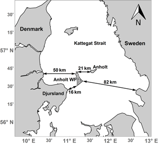
The Anholt Offshore Wind Farm is located in the Kattegat Strait of Denmark in the waters between Djursland and the island of Anholt in an area with fairly consistent water depths of about 15 to 19 m, see Fig. 1. The Anholt Offshore Wind Farm is approximately 20 km long and up to 8 km wide. The shortest distance to Djursland is 16 km, and there are 21 km to the island of Anholt. The Anholt wind farm consists of 111 Siemens SWT-120-3.6 MW wind turbines with a rotor diameter of 120 m with a total capacity of 400 MW and it was constructed during 2012–2013. The internal wind turbine spacing is 5–7 rotor diameters.
2.2 SAR wind fields
Wind fields retrieved from two different satellite SAR missions are used in this study. Envisat ASAR from the European Space Agency (ESA) acquired images between August 2002 and April 2012 before the construction of the Anholt wind farm. The mission was followed up by a constellation of two ESA satellites, Sentinel-1A and B, from which data are available since December 2014 and April 2016, respectively. Data until May 2017 are included for this study. The entire Sentinel-1 data series is recorded after construction of the wind farm at Anholt. The Copernicus programme publishes Envisat and Sentinel-1 A/B images under an open-access license, allowing for unlimited use, both for research and commercial applications.
SAR wind retrievals are indirect estimates of the wind speed that rely on the assumption that a measurement of the radar backscatter from the sea surface can be converted to a corresponding wind speed at the height 10 m. This is possible because the SAR observations are sensitive to centimetre-scale waves at the sea surface, which are generated by the instantaneous wind stress. Phenomena that modify the small-scale ocean surface waves, i.e. biological or mineral films (Gade and Alpers, 1997), and sea states (Alpers et al., 1981) influence the wind speed retrieval. This adds uncertainties to the wind speed retrieval. Global validation studies of satellite wind retrievals against modelled wind speeds found an RMSE of 1.30 m s−1 (Hersbach, 2010), while validations against in situ measurements in the Baltic showed an RMSE of 1.17 m s−1 (Hasager et al., 2011). Both studies show that while the accuracy of individual wind speed retrievals is somewhat low, SAR wind fields capture the mean wind speed and its spatial variability well.
An archive of processed wind maps from Envisat and Sentinel-1 A and B over Europe is available from DTU Wind Energy2. Our analyses are based on these readily available SAR wind maps. In the archive, wind speeds are retrieved from the SAR scenes using the SAR Ocean Products System (SAROPS; Monaldo et al., 2015). The GMF called CMOD5.N (Hersbach, 2010) is chosen for the wind speed retrieval, and wind directions are needed as an ancillary input for processing. We obtain the wind directions from the Climate Forecast System Reanalysis data set (CFSR3) during 2002–2010 and from the Global Forecasting System (GFS4) during 2011–2017. To reduce effects of random noise in the SAR imagery and to smooth out effects of longer period waves that modify the local radar incidence angle, the SAR scenes are resampled to 500 m pixel size in connection with the wind retrieval processing. Hard targets like wind turbines or offshore substations cause a strong signal in SAR images. The increased backscatter signal will cause an overestimation of the retrieved wind speed and therefore, extremely bright resolution cells are filtered out of the SAR wind maps prior to our analyses.
2.3 SCADA data
SCADA systems monitor and record wind turbine data, i.e. power production or pitch angle. The wind turbine power curve links the free wind speed to a power production. This wind speed (hereafter SCADA wind speed) can be derived from power and pitch combined with the power curve provided by the turbine manufacturer. The power is monotonically increasing with the wind speed between cut-in and rated power. Therefore, the wind speed can be inferred for this region. From rated power to cut-out, the power is constant but the blades are pitched increasingly. For this region, the wind speed can be inferred from the pitch signal. The resulting wind speed is equivalent to the reference wind speed used to create the power curve and is treated as a measurement at hub height. An intercomparison between the turbines reveals that this is, in general, an acceptable approach.
A qualification procedure is used to eliminate periods where the wind turbines are not grid connected and are not producing power during a complete 10 min period or have been curtailed, meaning their power generation has been reduced. Unfortunately, the wind speed for turbine A05 deviates due to unknown reasons and will be excluded from the analysis. The remaining periods are applicable for analysis after a final examination of the power curve. Due to a lack of undisturbed mast measurements, the inflow conditions need to be derived from the operational wind turbine data themselves. The inflow reference wind direction is determined from calibrated and undisturbed selected wind turbine yaw positions on the edge of the wind farm (cf. Peña et al., 2018, for further details).
2.4 Numerical wind simulations
The numerical simulations used in this study are performed with WRF version 3.5 without wind farm parameterization. The total simulated period covers 28 years from 1990 to 2017. Simulations are performed in 10-day chunks. Each individual simulation extends in total over 11 days, with the first day being disregarded as a spin-up period. The computational domain consists of three nests with an 18, 6, and 2 km grid spacing. Here the outermost domain is forced by the (ECMWF) ERA-Interim Reanalysis (Dee et al., 2011) and the results of the innermost domain are used for the analysis. In the horizontal direction, the innermost domain extends over 854 and 604 km in the x and y direction. In the vertical direction, 41 vertical levels with model top at 50 hPa are used, with 9 levels being within 1000 m from the surface. Wind speeds at the turbine hub height are derived by logarithmic interpolation between the two closest model levels.
The most relevant physics parameterizations in the model set-up are the Yonsei University Scheme (YSU) Planetary Boundary Layer (PBL) scheme (Hong et al., 2006), and the MM5 similarity surface-layer scheme, as well as sea surface temperatures from NOAA/NCEP (Reynolds et al., 2010). Further details of the model set-up and its validation are given in Peña and Hahmann (2017). WRF wind directions are extracted at the same locations as for the SCADA-derived wind direction and averaged to a time series of representative wind directions.
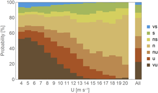
Figure 2Distribution of seven stability classes from very stable (vs) to very unstable (vu) based on 2.5 years of WRF simulations for wind speeds between 4 and 20 m s−1 and the distribution for all wind speeds labeled “all”.
The WRF model outputs include stability information expressed as the length scale z∕L. We use this to investigate the frequency of occurrence for different stability classes at the Anholt site. Stability classes at the turbine hub height are defined using the definitions from Hansen et al. (2012) for WRF simulations coinciding with the SCADA time series at the wind farm location, see Fig. 2. For low and intermediate wind speeds (< 15 m s−1), the atmospheric stratification is neutral up to 50 % of the time, whereas stable conditions occur less than 10 % of the time. The occurrence of neutral stratification is increasing with the wind speed. For wind speeds higher than 15 m s−1, the neutral stratification is dominant. These findings agree qualitatively with results from meteorological masts at the North Sea in Denmark (Floors et al., 2011; Peña et al., 2016) but differ from simulations and measurements of stratification in the Baltic, where stable stratification occurs more frequently (Smedman et al., 1997).
2.5 Wind speed extrapolation
SAR wind speeds are retrieved for a height of 10 m and SCADA wind speeds are representative for the wind turbine hub height at 81.6 m. A wind profile needs to be applied to perform wind speed extrapolation between these two levels, which will introduce additional uncertainty in the comparison. Lange et al. (2004) showed that uncertainties in extrapolating wind speeds from 10 to 50 m using different stability measurements introduce an RMSE of up to 6 %. For the Anholt site, local measurements of atmospheric stability effects are not available on site. Stability information from mesoscale models is not sufficiently accurate to perform a stability correction of the wind profile for individual SAR samples (Peña and Hahmann, 2012; Badger et al., 2016). For the present study, we assume a logarithmic wind profile with a wind speed dependent roughness length using Charnock's relation and the Charnock parameter (Grachev and Fairall, 1996). This will introduce larger uncertainties for extrapolation, especially under stable conditions. Low level jets that are known to occur in the region (Smedman et al., 1997) could add additional uncertainty in the wind speed extrapolation. It is out of the scope of this paper to assess the extrapolation uncertainty accurately, but we will test the influence of assuming a slightly stable or unstable wind profile (Wyngaard, 2010, p. 222).
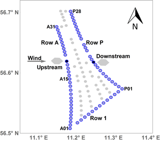
Figure 3Sketch of the Anholt wind farm where turbines in rows A, P, and 1 are used for comparisons and marked in blue. The remaining turbines are located at the grey circles. The grey hexagons are examples of footprints used for extracting the average SAR wind speeds upstream and downstream of the wind turbines for an example wind direction of 270∘. The turbines used for comparisons in this example are marked in black.
Four different methods are applied to analyse SAR wind fields around the Anholt wind farm. These are listed in Table 1 together with the temporal coverage for SCADA, SAR, and WRF data used in the respective analysis. The SCADA winds are used as reference measurements. “Wind direction” specifies the data input used for selection of SAR wind fields in contrast to the wind direction used for the SAR wind retrieval described in Sect. 2.2. Averaged wind speeds can show strong gradients in two directions. In the following, the term “wind speed gradient” refers to wind speed changes perpendicular to the coastline whereas the term “wind speed variability” refers to changes in the wind speed at the turbines located along Row A, see Fig. 3. For SAR-based wake studies in Sects. 3.3 and 3.4, we assume that all turbines at Anholt are operational. Data about the overall turbine availability is not available for publication for proprietary reasons.
3.1 Comparison of wind speeds from SAR and SCADA
Comparisons between SAR wind speeds and SCADA winds are carried out upstream (free-stream conditions) and downstream (wake conditions) of the wind turbines at Anholt. SAR wind maps at a resolution of 500 m need to be further averaged in order to better represent the wind conditions measured as 10 min means at the turbine locations (Christiansen and Hasager, 2005). SAR wind speeds at the turbine locations are contaminated by reflection from the wind turbines. It is thus necessary to extract resolution cells on the upstream or downstream side of the turbines. We extract and average SAR resolution cells within a hexagonal footprint inspired by the method of Gash (1986). The method was previously applied to SAR wind maps by Hasager et al. (2004). The hexagonal shape is aligned with the wind direction and extends from 600 to 2600 m from each turbine with a maximum width of 1200 m. Wind directions from SCADA are used for the directional alignment. Figure 3 shows example footprints for a situation with westerly winds. Resolution cells are extracted from the SAR wind maps if their centre point falls within the footprints defined. Within each footprint, the average wind speed is determined and compared with the corresponding SCADA wind speed. Comparisons are done along the turbine rows A, P, and 1 on the edge of the wind farm for the wind direction intervals shown in Table 2.
Logarithmic wind profiles are used to extrapolate SAR wind speeds up to the turbine hub height at 81.6 m. Extrapolation of SCADA winds from hub height down to 10 m, where the SAR winds are retrieved, is included as well since references on SAR wind speed accuracy are given for this height. The following results are based on SAR wind maps from 47 Sentinel-1A images collocated with the available SCADA data.
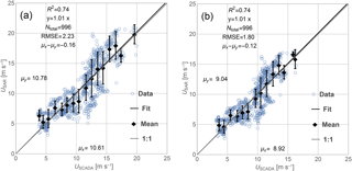
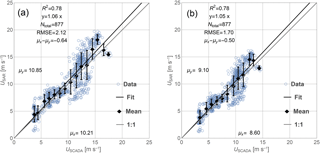
Figure 4Comparison between SCADA-derived wind speeds (USCADA) and SAR-derived wind speeds (USAR) upstream of the wind turbines: (a) for the turbine hub height (81.6 m) and (b) for the reference height (10 m).
3.1.1 Upstream
Comparisons at hub height upstream of the wind turbines are shown in Fig. 4. SCADA wind speeds at hub height range from 4 to 20 m s−1 covering most of the range of wind turbine operation. Comparisons with SAR wind speeds yield a mean bias of −0.16 m s−1, meaning a slight tendency of SAR to estimate higher winds. The correlations coefficient (R2) of the linear fit through the origin is 0.74, the slope of the fit is close to 1, and the RMSE is 2.33 m s−1. Wind speeds at 10 m in Fig. 4b are generally lower and the RMSE of the comparison is lower due to this (1.80 m s−1).
The low bias, good correlation, and slopes close to 1 suggest that averaged SAR wind speeds are a good representation of the wind conditions as experienced by the wind turbines under free-stream conditions. Using the wind direction from the SCADA system for the SAR wind retrieval process reduces the RMSE by approximately 0.1 m s−1 (not shown). This is a small improvement compared to the overall accuracy of the SAR wind retrieval, thus supporting the SAR processing choice. Assuming near-stable and near-unstable stratification changes the RMSE (Fig. 4b) by less than 0.1 m s−1 but it does change the bias to −0.68 and 0.19 m s−1, respectively.
3.1.2 Downstream
Figure 5 shows comparisons of SAR and SCADA wind speeds on the downstream side of the wind turbines for wind direction intervals defined in Table 2. At hub height, the averaged SCADA wind speed is 10.20 m s−1 and comparisons to SAR give a bias of −0.64 m s−1, again towards higher wind speeds from SAR. The correlation coefficient of 0.78 is good for a linear fit with a slope of 1.06, and the RMSE is 2.12 m s−1. Again, the correlation coefficient and the slope at 10 m height are similar whereas the RMSE is lower (1.7 m s−1). The mean bias is numerically smaller at 10 m (−0.50 m s−1) than at hub height (−0.64 m s−1).
The bias is numerically higher downstream compared to upstream of the wind farm whereas the RMSE for downstream conditions is approx. 0.1 m s−1 lower than for upstream conditions. The lower RMSE seems counterintuitive, since we expect the assumption of a single logarithmic wind profile from the surface to hub height to be better satisfied upstream than downstream of the wind turbines due to wake effects. The number of observation pairs is higher upstream (996) than for downstream (877) as a result of the SAR image coverage and a reduced number of turbine locations downstream for the prevailing westerly wind directions. The sampling difference may influence our results.
3.2 Wind speed variability along Row A
Observations of the past wind conditions are typically used in wind resource assessment to estimate the wind conditions a potential wind farm would be exposed to. Satellite SAR observations are available 10 years before the wind farm at Anholt was constructed. Peña et al. (2018) have shown a large variability of mean wind speeds for the western Row A between 245 and 275∘ from SCADA and WRF results. They are created by the roughness change between land and sea and are determined by differences in fetch caused by the shape of the peninsula (Van Der Laan et al., 2017). Here we investigate whether the variability in the mean wind speed at the site could be predicted from SAR wind maps prior to the wind farm construction. Our analysis of SAR wind maps is complemented by an analysis of numerical simulations from WRF, which are also available to a developer prior to the wind farm construction. The overall data availability for SCADA, SAR, and WRF is shown in Table 1 and the number of observations used in this analysis is shown in Table 3.
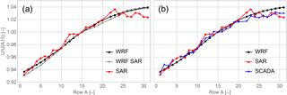
Figure 6Average wind speed relative to turbine A15 for wind directions between 245 and 275∘. (a) Data from WRF (2002–2012) and SAR (2002–2012). The entire time period is used for “WRF” and WRF data coinciding with SAR images are used in “WRF SAR”. (b) Data from full WRF time series, SAR, and SCADA (2013–2015). No turbine was erected at location A21.
SAR wind speeds at the turbine locations of Row A are extracted as described in Sect. 3.1 for upstream situations. For the WRF simulations, hourly WRF wind speeds at hub height are interpolated for each of the turbine locations before they are averaged. Both data sets are filtered according to the following conditions: (i) wind directions are between 245 and 275∘, (ii) there is full availability of measurements for all turbine locations along Row A, and (iii) wind speeds averaged over Row A are above the cut-in wind speed of the wind turbine. The averaged wind speeds are non-dimensionalized through division with the respective wind speed at turbine position A15 (see Fig. 3) giving a relative measure of wind speed variability along Row A.
The wind speed variability from SAR and WRF is first examined using two different sampling scenarios for the WRF simulations: the full WRF data set (2002 to 2012) and the WRF samples collocated with the SAR scenes, see Fig. 6a. For both scenarios, the WRF simulations show a smooth and monotonically increasing mean wind speed from south to north along Row A. The maximum deviation of mean wind speeds from the two WRF data sets is below 0.5 %. This suggests that the reduced sampling rate, which corresponds to the sampling of SAR observations, has little effect on the mean wind speed. The wind speed variability from SAR observations is less smooth and shows a local maximum at turbine A23. SAR winds are increasing from south to north until they stay approximately constant from turbine A24 on. The wind speed variability from SAR is in good agreement with the two WRF data sets from turbine A01 until A25 where the SAR wind speeds start to decrease.
The relative mean wind speeds from SAR and WRF along Row A are compared to SCADA wind speeds in Fig. 6b. All available data from both SAR and WRF before wind farm construction are used to best approximate the wind speed climatology from each data set. The SCADA winds, in contrast, cover a shorter period after the wind farm construction. There is a clear increase in the wind speed from turbine A01 until A20 in agreement with both the SAR and WRF data sets, but the result for turbine A05 has been left out as mentioned in Sect. 2.3. From position A24, SCADA and SAR winds show a similar behaviour, whereas WRF winds are consistently higher and with less spatial variability. We can summarize the findings above as wind speed differences between the southernmost and northernmost turbines. The difference ΔUN,S is defined as
where Ui is the mean wind speed at the turbine location. The difference between the northern and the southern part of the wind farm is given in Table 3. SCADA and SAR agree within 0.1 percentage point while WRF predicts a 1 percentage point larger difference than SCADA results suggest.
The wind speed variability along Row A, as shown in Fig. 6 and Table 3, is likely caused by varying fetch from the coastline of Djursland. The fetch at different positions along Row A can vary between 16 and 50 km for the same wind direction, see Fig. 1. The agreement between non-dimensional wind speeds from SAR and SCADA is remarkably good. We can conclude that for this site, wind speeds retrieved from SAR imagery could have predicted the relative wind speed gradients well, before construction of the wind farm.
We test the influence of extrapolation by assuming the turbine hub height is within the surface layer and that both the atmospheric stability and the aerodynamic roughness length are constant along turbine Row A. The relative wind speed should thus show little dependence in the height since the stability correction term has the same value. This has been tested assuming near-stable and near-unstable conditions. The resulting extrapolated wind speed (not shown) differs between −0.4 (unstable) and 0.6 m s−1 (stable), while the results relative to turbine position 15 show differences below 0.01 percentage points. These assumptions will not be valid at all times, but the extrapolation error of the mean wind speed from 10 m to hub height is expected to be reduced when the mean wind speed is divided by the mean wind speed at a reference location.
3.3 Wind farm wakes from SAR
To investigate the impact of the Anholt wind farm on the wind conditions in the area, we compare wind speeds extracted from SAR wind maps along two transects before and after wind farm construction. With this approach, a baseline of wind conditions before wind farm construction can be determined assuming that the wind conditions in the period before and after the wind farm construction are similar.
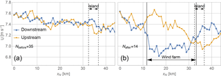
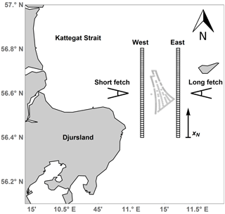
Figure 8Wind speed transects from (a) before and (b) after wind farm construction for wind directions between 75 and 105∘. Transect East is upstream and transect West is downstream of the (potential) wind farm location. The position of the wind farm to the east–west and Anholt Island to the east of the transects are indicated.
Wind farm wakes at Anholt are analysed for two wind direction sectors. The first sector (75–105∘) represents easterly wind directions and a long fetch. The second sector (255–285∘) represents westerly wind directions and a short fetch, see Fig. 1. Wind direction information from WRF is used for the selection of SAR wind maps within the two sectors as described in Sect. 2.4. Three additional criteria are set for SAR wind fields to be included in this analysis: (i) the images must fully cover both transects; (ii) the mean wind speed at 10 m over the inflow transect is within the interval 3–12 m s−1, where we expect wind farm wakes to be strongest; and (iii) visual inspection does not show any strong signals that are uncorrelated with the wind speed, e.g. rain contamination.
Figure 7 shows the position of the two transects. Transect “East” is located between 2 and 10 km to the east of the wind farm and transect “West” is located between 4 and 6 km to the west of the wind farm. Along each of the transects, wind speeds are extracted from all available SAR wind maps and averaged over rectangular bins of 1 km (in the transect direction) and 1.5 km (perpendicular to transect direction). Resolution cells showing more than 5 m s−1 difference from the median within each bin are filtered out as they likely result from reflection from ships.
Wind speed pairs extracted at the same latitude from the East and West transects are assumed to be upstream or downstream of each other for the two directional sectors investigated here. We can calculate the difference Δui between upstream and downstream observations depending on xN:
where ui,up(xN) and ui,down(xN) are the wind speeds on transect “upstream” and “downstream”, respectively. From Δu(xN) we can calculate the mean difference ΔU(xN) and the standard error SE(xN). As defined here, a positive ΔU corresponds to a wind speed reduction on the downstream transect.
3.3.1 Long fetch
For situations with easterly winds the transect “East” is upstream and transect “West” downstream of the wind farm. The fetch is approximately 80 km to the east with the exception of the Anholt Island, see Fig. 1. A total of 49 SAR wind maps live up to our selection criteria. Of these, 35 were acquired by Envisat before the wind farm was constructed and 14 were acquired by Sentinel-1 after the wind farm construction. Figure 8a shows the average wind speeds along upstream and downstream transects before the wind farm construction. The wind speeds at the same latitude are very similar over the distance 0 to 32 km. This is as expected since there is open water between the transects and the fetch is long. At 32–37 km, where Anholt island is upstream of both transects, the wind speeds on the upstream transect are slightly lower compared to those along the downstream transect. This is likely caused by the lee effects from the island. Figure 8b shows the average wind speed along the two transects after the wind farm was constructed. The wind speed along the downstream transect shows a reduction between 11 and 30 km. The wind speed along the upstream transect remains between 7.3 and 7.6 m s−1 from 0 to 25 km and decreases further north. The number of observations is much lower than before the wind farm construction.
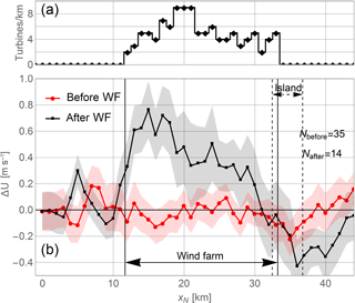
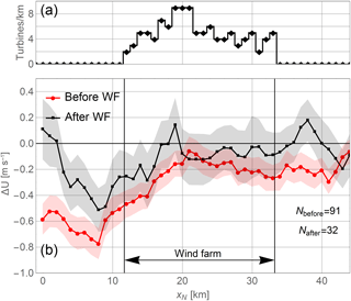
Figure 9(a) Density of turbines per unit kilometre between the transects. (b) Mean difference between wind speeds on the upstream and downstream transects before and after construction of the Anholt wind farm. Vertical lines indicate the position of the wind farm and dashed lines the position of the island Anholt to the east. The shaded area represents one standard error around the mean.
Figure 9 shows the mean wind speed differences ΔU with one standard error, SE, indicated by the shaded areas. The average density of turbines between the upstream and downstream transects are shown at the top. Before the wind farm construction, the differences range from −0.2 to 0.2 m s−1 from 0 until 30 km. ΔU is negative from 29 until 37 km around the position of Anholt Island, likely corresponding to a lee effect of the island. After the wind farm construction, the influence of the wind farm is clearly visible from a difference of 0.3 to 0.75 m s−1 between 11 and 27 km. This coincides with the distance where the highest density of turbines is found. Ranges of the standard error shown as the shaded regions are also clearly separated. Around the location of Anholt island, the differences are slightly negative and similar to the differences found before the wind farm construction. At 6 km, a peak around 0.3 m s−1 appears. The reason for this peak is unclear but could be non-wind effects such as bathymetry–current interaction or remaining effects of hard targets, which influence the radar backscatter and thus the wind speed retrieval.
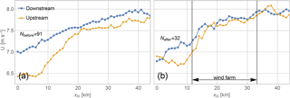
Figure 10Wind speed transects similar to Fig. 8 from (a) before and (b) after construction for wind directions between 255 and 285∘. Transect West is upstream and East is downstream of the (potential) wind farm location.
A sample size of 35 images creates the baseline of the wind conditions before construction of the wind farm. SAR wind speeds after construction show a clear wake, both absolute and relative to the state before construction of the wind farm, see Figs. 8 and 9. Even though the sample size of 14 images after wind farm construction is small, there is clear indication of the wind farm wake.
3.3.2 Short fetch
For situations with westerly winds the transect West is located upstream and transect East is downstream of the wind farm. The fetch is between 16 and 50 km to the west, see Fig. 1. Average wind speeds along the two transects are analysed in a similar manner as described for the long fetch situations in Sect. 3.3.1. A total of 92 images before and 31 after wind farm construction fulfil the selection criteria. Figure 10 shows the averaged wind speeds. The wind speeds are increasing from south to north along both transects. Wind speeds from before wind farm construction in Fig. 10a are consistently lower for the upstream compared to the downstream transect. This is expected due to the increasing wind speed further offshore. All transects in Fig. 10 show lower wind speeds in the southern end than in the northern end. This variability in the wind speed is similar to the one found in Sect. 3.2 and likely caused by the variation in fetch along the transects. Wind speed differences and standard error are calculated similar to Sect. 3.3.1 and are shown in Fig. 11.
The wind speed difference before wind farm construction ranges between −0.7 and −0.4 m s−1 for the area south of the potential wind farm. Further north from 17 km on, the difference ranges between −0.3 and −0.1 m s−1. This is consistent with a short fetch in the south where wind speed is expected to speed up more between the transects than in the northern part with longer fetches. Wind speed differences after construction of the wind farm show roughly the same pattern except between 0 and 8 km where differences are large. No clear evidence of wind farm wake effects are found since no significant difference is noted between the average wind speeds before and after wind farm construction. The number of observations before wind farm construction is approximately 3 times larger than after. The averaged wind speed after construction is less smooth. The convergence to a smoother mean wind speed is expected in the future as more observations from Sentinel-1 A and B become available.
3.4 Wind farm wakes and gradients
To analyse the cumulative effect of coastal wind speed gradients and the wind farm wake effect, four parallel transects are defined perpendicular to the coastline following the orientation of wind turbine Row 1. Figure 12 shows a reference transect to the north of the Anholt wind farm (labelled a) and three transects across the wind farm (labelled b, c, and d). Average wind speeds are extracted along these transects similarly to the extraction in Sect. 3.3.
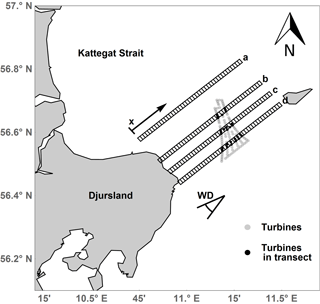
Figure 12Transects used for analysis of wind farm wakes and coastal gradients. Origin and direction of coordinate x, and the wind direction range (WD) used for the selection of satellite scenes are indicated.
For this analysis, SAR wind maps are selected according to the following three criteria: (i) there is full coverage over all four transects, (ii) SAR wind speeds at 10 m upstream of the wind farm are between 3 and 12 m s−1, and (iii) the wind is coming from directions within the sector 214.5–244.5∘ centred around the transect orientation and roughly corresponding to the prevailing wind direction at the site. WRF outputs are used to determine the wind direction as described in Sect. 2.4. A total of 57 images before and 35 after the wind farm construction fulfil these criteria.
SCADA wind speeds are extracted for the wind turbine locations covered by transectd b, c, and d. The following criteria are used for filtering of the SCADA wind speeds: (i) the turbine locations are within the transects and data are available for all those turbines, see Fig. 12; (ii) SAR wind speeds at 10 m upstream of the wind farm are between 3 m s−1 and 12 m s−1; and (iii) the wind is coming from directions within the sector 214.5–244.5∘. A total of 3371 10-min mean values of SCADA wind speeds live up to these criteria. Data from SAR and SCADA are not collocated in time. The wind turbines are placed in rows oriented from north to south. SCADA wind speeds are averaged for each row segment within each transect.
SAR wind speeds are presented as differences with respect to a reference wind speed, Uref, upstream of the wind farm (for transect b, c, and d). For transect a, the reference point is at the same x position as for transect b. SCADA winds are shown as wind speed differences compared to the free-stream turbines in Row A. Wind speed differences along transects a to d are shown in Fig. 11. Before the wind farm construction, there is a clear coastal wind speed gradient with increasing wind speeds with distance from the coastline for all four transects. For the reference transect a, the deviation between the results before and after wind farm construction is below 0.2 m s−1.
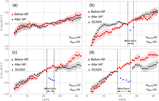
Figure 13Wind speed differences from SAR along transects a to d before and after construction of the wind farm. Differences calculated from SCADA wind speeds are also shown and the position of the wind farm is indicated.
Upstream of the wind farm, transects b, c, and d clearly show wind speed gradients both before and after wind farm construction. For transects c and d wind speed differences before and after the wind farm construction agree within 0.2 m s−1, whereas larger deviations are found at transect b. These deviations might be caused by variations in the fetch. Wind speeds extracted along transect b are likely to be very sensitive to the local wind direction because transect b is located close to the northern side of the Djursland peninsula. Here, a small change in the wind direction could lead to a large increase or decrease in the fetch, see Fig. 12. An increase in the fetch is usually associated with an increase in the wind speed. Therefore, a higher occurrence of wind directions west of 235∘ after construction of the wind farm could be the reason for the deviations observed for transect b. Transects c and d would be less affected by variations in the wind direction since they are located further south where the fetch varies less for southwesterly wind directions. The wind direction used for the selection of SAR images comes from WRF simulations at the wind farm location. Any local variability of the wind direction is not resolved by WRF and the true wind direction along the four transects might thus deviate from the WRF wind direction. Since we do not have in situ measurements for the entire period considered here, it is not possible to determine the exact difference in the wind direction distribution.
Wind speeds downstream of the wind farm show a positive wind speed gradient along transects b, c, and d. Here, the wind speed at transect b is similar before and after wind farm construction. This transect crosses a narrow part of wind farm with only three turbine rows. Transects c and d cross a larger number of turbines and show a significant change of the wind speed after the wind farm construction and we attribute this change to wake effects of the wind turbines. SAR wind speeds cannot be retrieved correctly within the wind farm itself due to radar reflection from the turbines. The SCADA wind speeds for turbines within transect b to d are used instead to describe the wind speed behaviour within the wind farm. The SCADA wind speeds suggest a reduction of wind speeds downstream of turbine Row A, which is most pronounced for transects c and d crossing many turbine rows.
SCADA wind speeds show the wind farm wake as a reduction in wind speed compared to the upstream turbine. SAR winds on transects c and d show a reduction of wind speed compared to the situation before construction of the wind farm. The deviations between these two types of wind speed information are between 0.3 and 0.6 m s−1. Differences between SAR and SCADA winds may be attributed to (i) a difference in the location with SCADA winds at the turbine positions and SAR winds downstream of the wind farm, (ii) differences in the sample size and measurements that are not collocated in time, or (iii) differences in the vertical position of the measurements. SCADA data are derived at the turbine operating height whereas the SAR wind retrievals are based on observations of the sea surface. The strongest wind turbine wake effect is expected at the turbine hub height, which is consistent with a stronger wake from SCADA winds compared to SAR.
We have demonstrated how an extensive archive of SAR wind maps can be used to identify the combined effects of a complex coastal geometry and wind farm wakes on the mean wind conditions around the Anholt wind farm. Our results illustrate how wind maps retrieved from SAR can predict the wind conditions that offshore wind turbines and whole wind farms experience before a wind farm is constructed.
For the first time, wind speeds derived from the SCADA system of an entire wind farm have been compared to SAR wind speeds, see Fig. 4. The correlation for free-stream conditions is good and the slope of the fit is very close to 1. This result is encouraging for using SAR-derived mean wind speeds to predict wind conditions as experienced by the wind turbines. GMFs used for SAR wind retrieval are tuned using observational data from buoys in the open ocean. Influences of internal boundary layers caused by the roughness change between land and sea, or effects of limited fetch on the ocean surface roughness are not fully accounted for. These effects are hard to quantify, but the RMSE compared to lidar measurements in the coastal zone is between 1.3 and 1.4 m s−1 (Ahsbahs et al., 2017). The SAR wind speed retrieval process needs a wind direction as an input. Readily available SAR wind maps using a global model wind direction are used throughout this study. Therefore, uncertainties in the modelled wind direction translate into errors in the wind speed retrievals.
The Anholt wind farm experiences strong variability in the wind speed along the westernmost row (Row A) for the prevailing wind directions from 245–275∘. Comparisons of WRF mean wind variability from the full time series with a downsampled data set matching 72 SAR images before construction show similar results. This strengthens the assumption that the available SAR images correctly represent the mean wind conditions at the Anholt site. The normalized mean wind speed obtained from SAR before construction of the wind farm agrees very well with results from SCADA winds of the first 2.5 years of wind farm operation. The mean wind speed between the south and north of Row A increases by 8.7 % in the SCADA wind speeds and 8.8 % in SAR-derived wind speeds, see Table 3. SAR wind maps are thus valuable for characterization of large-scale flow phenomena such as wind speed variations over long rows of turbines. Variability in the wind speed relative to a reference location is expected to show little influence from atmospheric stability as presented in Sect. 3.2. The validity of this claim hinges on assumptions of surface layer theory, constant roughness, and stability over the domain. A more detailed study to test these assumptions could support the use of SAR for detection of wind speed variabilities.
For this site, non-dimensional wind speeds from WRF at the turbine locations also predict wind speed variability very similar to results from SAR and SCADA. Models such as WRF are powerful tools to identify good wind resources, but cannot fully replace observations of the wind conditions on site. The presented analysis of SAR wind maps can complement modelling efforts by introducing an independent measurement for comparison, since both data sets are available before construction of a potential wind farm. A good agreement between WRF and SAR with regard to wind speed variability can add confidence to wind resource assessment. Further studies at locations where the mean wind speed is affected by an upstream shoreline could show if agreement between SAR and NWP modelling is common and if disagreements could point towards an increased uncertainty in the NWP modelled wind resources.
Comparisons in the wake (see Fig. 5) showed a lower scatter than free-stream comparisons suggesting a better fit in waked compared to free-stream conditions, even though the assumptions of a fully developed wind profile are violated by the presence of a wake. Further studies of SAR wind retrievals within wind farm wakes using high-quality reference measurements at several heights from the sea surface to the turbine hub height are needed to examine this finding in more detail.
The correlation of downstream comparison is good but the bias towards higher wind speeds from SAR has increased compared to the analysis upstream of the wind farm, see Figs. 4 and 5. The largest wake deficit is located at hub height (Porté-Agel et al., 2011) and this could cause an overprediction of the SAR wind speed when extrapolated in Fig. 5. Additionally, SAR winds are retrieved between 600 and 2600 m downstream of the turbine position but are compared to SCADA wind speeds at the turbine location and the wake is likely to recover. This is also consistent with the difference between SAR and SCADA winds in Fig. 13. To better quantify wind farm wakes from SAR images, further work is needed to understand how wakes interact with the ocean surface and how this influences SAR wind retrievals.
Anholt wind farm has irregular turbine spacing and the shape is elongated. Methods applied at other offshore wind farm sites for analysing wakes in SAR wind maps (Hasager et al., 2015b) are less suitable for Anholt. A new approach for analysing wind farm wakes from SAR images has therefore been suggested here, which explores the difference of SAR wind maps before and after the wind farm was constructed. The wind farm wake effects are analysed along transects approximately perpendicular to the wind direction on the upstream versus the downstream side of the wind farm and along transects crossing the wind farm aligned with the wind direction. For situations with a long fetch, perpendicular transects before wind farm construction provide a suitable baseline to check averaged differences between upstream and downstream transects, see Fig. 9. The wind farm wake estimated from SAR shows a structure that roughly follows the turbine density of the wind farm. In contrast, no indication of a wake is found in Fig. 11. The wind direction sector overlaps with the sector from Fig. 6 where strong horizontal wind speed variability was found, which will also affect the transects. A possible explanation could be that the upstream orography is more complex for the short compared to the long fetch scenario. This could affect the similarity of the wind conditions for the SAR images before and after wind farm construction, either due to difference in the wind direction or atmospheric stratification.
Transects crossing the wind farm can be used to investigate how the coastal wind speed gradient and wakes of the wind farm interact, see Fig. 13. No wind speed reductions compared to the upstream reference point are found but two transects going through an area of high wind turbine density show a reduction of the mean wind speed after wind farm construction compared to the situation before. This result stands in contrast to Fig. 11 and transect b in Fig. 13 where no evidence of a wind farm wake was found. Identification of wakes from SAR images is not trivial when an upstream coastline is influencing the flow. Further studies at locations with simple geometry of the coastline would help to understand the interplay of wind farm wakes and coastal wind speed gradients.
SAR wind maps are suitable for analysing large-scale wind conditions and they can show the combined effects of different flow phenomena. In this analysis, wind farm wakes, coastal wind speed gradients, and wind speed variability from differing fetch occur simultaneously. It is challenging to identify the contribution of one particular flow phenomenon, e.g. wind farm wakes from these data. In contrast to engineering wake models such as Fuga or Park that are run with a single wind speed and direction, SAR wind maps capture the full picture of the flow around a wind farm. The presented methods can potentially be repeated for any offshore wind farm site even before the wind farm construction.
The presented SAR data archive goes back to 2002 and offers the possibility of reference measurements before most of the current offshore wind farms were constructed. The analyses presented in this study will gain confidence as the satellite data archives are growing over time. With Sentinel-1 A and B, two new satellites are acquiring new scenes on a daily basis which are available in the public domain. This makes SAR observations and derived wind maps more accessible and the time is right to develop tools for SAR data analysis that are tailored to the needs of the offshore wind industry.
Large archives of SAR wind maps have recently become publicly available and the sampling frequency of the measurements has increased significantly with the European SAR missions Sentinel-1 A/B. Readily available SAR-based wind speed maps represent a computationally and monetarily cheap source of information about the large-scale wind speed variability offshore. The maps are available in hindcast and may thus be used from the earliest stages of a wind farm project. We have demonstrated that wind speed maps retrieved from SAR observations of radar backscatter can be used to predict the spatial wind speed variability at a potential wind farm site before construction begins. The satellite-based wind speed maps can also be used for characterization of wake effects around existing wind farms and to partially determine the cumulative effects of coastal wind speed gradients and wake effects.
Wind speeds retrieved from SAR correlate well with the SCADA-derived wind speeds for the turbines at Anholt wind farm. RMSEs are 2.23 and 2.12 m s−1 for comparisons upstream and downstream of the wind farm, respectively. Wind farm wakes are detected from SAR wind fields using a long time series with measurements before and after construction of the wind farm. This approach is promising, since a baseline of wind conditions before the construction is available. Wind farm wake effects are found for wind directions leading to a long fetch with a maximum deficit of 0.7 m s−1. Wind farm wakes at fetch-limited conditions are harder to identify possibly due to the complex interplay of different effects such as varying fetch and coastal wind speed gradients on the mean wind speed. More studies using these approaches for different wind farms are necessary, ideally with in situ reference measurements, to determine the capabilities of SAR for wind farm wake detection.
Our results show that SAR wind maps can resolve smaller-scale wind variability comparable to SCADA wind speeds. WRF and SAR data sets are independent of each other and are available in the early stages of planning an offshore wind farm. Alongside model simulations, satellite-based wind maps represent a valuable resource to introduce large-scale on-site measurements early in an offshore wind farm project, i.e. for planning of in situ measurement campaigns.
SAR wind fields are available at https://satwinds.windenergy.dtu.dk/ (DTU Wind Energy, 2018) and WRF model runs can be made available upon request. SCADA data are not available for publication.
TA developed methods and code. MB and CBH provided the processed SAR wind maps and contributed with guidance and comments. KSH prepared the SCADA data and PV provided the WRF data. TA prepared the manuscript with contributions from all co-authors. This work is part of TA's PhD under supervision of MB.
The authors declare that they have no conflict of interest.
We would like to acknowledge Ørsted for granting access to data from the
Anholt wind farm, Johns Hopkins University Applied Physics Laboratory and the
National Atmospheric and Oceanographic Administration (NOAA) for the use of
the SAROPS system and the ESA for providing public access to data from Sentinel-1A.
This work received funding from the EU H2020 program under grant agreement no. 730030 (CEASELESS project).
Personal thanks to Nicolai G. Nygaard from Ørsted for his approval and comments.
Edited by: Julie Lundquist
Reviewed by: two anonymous referees
Ahsbahs, T., Badger, M., Karagali, I., and Larsén, X. G.: Validation of Sentinel-1A SAR Coastal Wind Speeds Against Scanning LiDAR, Remote Sens., 9, p. 552, 2017.
Alpers, W. R., Ross, D. B., and Rufenach, C. L.: On the detectability of ocean surface waves by real and synthetic aperture radar, J. Geophys. Res., 86, 6481–6498, https://doi.org/10.1029/JC086iC07p06481, 1981.
Badger, M., Peña, A., Hahmann, A. N., Mouche, A. A., and Hasager, C. B.: Extrapolating Satellite Winds to Turbine Operating Heights, J. Appl. Meteorol. Climatol., 55, 975–991, 2016.
Barthelmie, R. J., Badger, J., Pryor, S. C., Hasager, C. B., Christiansen, M. B., and Jørgensen, B. H.: Offshore Coastal Wind Speed Gradients: issues for the design and development of large offshore windfarms, Wind Engin., 31, 369–382, 2007.
Barthelmie, R. J., Pryor, S. C., Frandsen, S. T., Hansen, K. S., Schepers, J. G., Rados, K., and Neckelmann, S.: Quantifying the Impact of Wind Turbine Wakes on Power Output at Offshore Wind Farms, J. Atmos. Ocean. Technol., 27, 1302–1317, 2010.
Christiansen, M. B. and Hasager, C. B.: Wake effects of large offshore wind farms identified from satellite SAR, Remote Sens. Environ., 98, 251–268, 2005.
Christiansen, M. B., Koch, W., Horstmann, J., Hasager, C. B., and Nielsen, M.: Wind resource assessment from C-band SAR, Remote Sens. Environ., 105, 68–81, 2006.
Dagestad, K.-F., Horstmann, J., Mouche, A., Perrie, W., and Shen, H.: Wind Retrieval From Synthetic Aperture Radar, an Overview, in: Seasar 2012 Oceanography Workshop, European Space Agency, ESA, 2013.
Dee, D. P., Uppala, S. M., Simmons, A. J., Berrisford, P., Poli, P., Kobayashi, S., and Vitart, F.: The ERA-Interim reanalysis: Configuration and performance of the data assimilation system, Q. J. Roy. Meteor. Soc., 137, 553–597, 2011.
Dörenkämper, M., Optis, M., Monahan, A., and Steinfeld, G.: On the Offshore Advection of Boundary-Layer Structures and the Influence on Offshore Wind Conditions, Bound.-Lay. Meteorol., 155, 459–482, https://doi.org/10.1007/s10546-015-0008-x, 2015.
DTU Wind Energy: Satellite Winds, available at: https://satwinds.windenergy.dtu.dk/ last access: 20 August 2018.
Fitch, A. C., Olson, J. B., Lundquist, J. K., Dudhia, J., Gupta, A. K., Michalakes, J., and Barstad, I.: Local and Mesoscale Impacts of Wind Farms as Parameterized in a Mesoscale NWP Model, Mon. Weather Rev., 140, 3017–3038, https://doi.org/10.1175/MWR-D-11-00352.1, 2012.
Floors, R., Gryning, S. E., Pena, A., and Batchvarova, E.: Analysis of diabatic flow modification in the internal boundary layer, Meteorol. Z., 20, 649–659, 2011.
Gade, M. and Alpers, W.: Using ERS-2 SAR images for routine observation of marine pollution in European coastal waters, Sci. Total Environ., 237/238, 441–448, 1997.
Gash, J. H. C.: A Note on Estimating the Effect of a Limited Fetch on Micrometeorological Evaporation Measurements, Bound.-Lay. Meteorol., 35, 409–413, 1986.
Grachev, A. A. and Fairall, C. W.: Dependence of the Monin-Obukhov Stability Parameter on the Bulk Richardson Number over the Ocean, J. Appl. Meteorol., 36, 406–414, 1996.
Hahmann, A. N., Vincent, C. L., Peña, A., Lange, J., and Hasager, C. B.: Wind climate estimation using WRF model output: Method and model sensitivities over the sea, Int. J. Climatol., 35, 3422–3439, 2015.
Hansen, K. S., Barthelmie, R. J., Jensen, L. E., and Sommer, A.: The impact of turbulence intensity and atmospheric stability on power deficits due to wind turbine wakes at Horns Rev wind farm, Wind Energy, 15, 183–196, 2012.
Hansen, K. S., Réthoré, P. E., Palma, J., Hevia, B. G., Prospathopoulos, J., Peña, A., and Volker, P.: Simulation of wake effects between two wind farms, J. Phys.-Conf. Ser., 625, 012008, https://doi.org/10.1088/1742-6596/625/1/012008, 2015.
Hasager, C. B., Dellwik, E., Nielsen, M., and Furevik, B. R.: Validation of ERS-2 SAR offshore wind-speed maps in the North Sea, Int. J. Remote Sens., 25, 3817–3841, 2004.
Hasager, C. B., Badger, M., Peña, A., Larsén, X. G., and Bingöl, F.: SAR-based wind resource statistics in the Baltic Sea, Remote Sens., 3, 117–144, 2011.
Hasager, C. B., Mouche, A., Badger, M., Bingöl, F., Karagali, I., Driesenaar, T., and Longépé, N.: Offshore wind climatology based on synergetic use of Envisat ASAR, ASCAT and QuikSCAT, Remote Sens. Environ., 156, 247–263, 2015a.
Hasager, C. B., Vincent, P., Badger, J., Badger, M., Di Bella, A., Peña, A., and Volker, P.: Using Satellite SAR to Characterize the Wind Flow around Offshore Wind Farms, Energies, 8, 5413–5439, 2015b.
Hersbach, H.: Comparison of C-Band Scatterometer CMOD5.N Equivalent Neutral Winds with ECMWF, J. Atmos. Ocean. Technol., 27, 721–736, 2010.
Hong, S.-Y., Noh, Y., and Dudhia, J.: A New Vertical Diffusion Package with an Explicit Treatment of Entrainment Processes, Month. Weather Rev., 134, 2318–2341, 2006.
Jensen, N. O.: A note on wind generator interaction (Risø-M-2411), Roskilde, 1983.
Lange, B., Larsen, S., Højstrup, J., and Barthelmie, R.: The influence of thermal effects on the wind speed profile of the coastal marine boundary layer, Bound.-Lay. Meteorol., 112, 587–617, 2004.
Larsen, G. C.: A simple stationary semi-analytical wake model, Risø National Laboratory for Sustainable Energy, Technical University of Denmark, 2009.
Li, X. and Lehner, S.: Observation of TerraSAR-X for Studies on Offshore Wind Turbine Wake in Near and Far Fields, IEEE J. Sel. Top. Appl., 6, 1757–1768, 2013.
Monaldo, F. M., Jackson, C. R., Pichel, W. G., and Li, X.: A Weather Eye on Coastal Winds, Eos, 96, 1–8, 2015.
Nygaard, N. G.: Wakes in very large wind farms and the effect of neighbouring wind farms, J. Phys. Conf. Ser., 524, 12162, https://doi.org/10.1088/1742-6596/524/1/012162, 2014.
Nygaard, N. G. and Hansen, S. D.: Wake effects between two neighbouring wind farms, J. Phys. Conf. Ser., 753, 32020, https://doi.org/10.1088/1742-6596/753/3/032020, 2016.
Ott, S., Berg, J., and Nielsen, M.: Linearised CFD Models for Wakes, Danmarks Tekniske Universitet, Risø Nationallaboratoriet for Bæredygtig Energi, 2011.
Peña, A. and Hahmann, A. N.: Atmospheric stability and turbulence fluxes at Horns Rev – an intercomparison of sonic, bulk and WRF model data, Wind Energy, 15 , 717–731, 2012.
Peña, A. and Hahmann, A. N.: 30-year mesoscale model simulations for the “Noise from wind turbines and risk of cardiovascular disease” project, DTU Wind Energy, 55, 1–27, 2017.
Peña, A., Floors, R., Sathe, A., Gryning, S. E., Wagner, R., Courtney, M. S., and Hasager, C. B.: Ten Years of Boundary-Layer and Wind-Power Meteorology at Hovsore, Denmark, Bound.-Lay. Meteorol., 158, 1–26, 2016.
Peña, A., Hansen, K. S., Ott, S., and van der Laan, M. P.: On wake modeling, wind-farm gradients, and AEP predictions at the Anholt wind farm, Wind Energ. Sci., 3, 191–202, https://doi.org/10.5194/wes-3-191-2018, 2018.
Platis, A., Siedersleben, S. K., Bange, J., Lampert, A., Bärfuss, K., Hankers, R., and Emeis, S.: First in situ evidence of wakes in the far field behind offshore wind farms, Sci. Rep., 8, 1–10, 2018.
Porté-Agel, F., Wu, Y.-T., Lu, H., and Conzemius, R. J.: Large-eddy simulation of atmospheric boundary layer flow through wind turbines and wind farms, J. Wind Eng. Ind. Aerod., 99, 154–168, 2011.
Quilfen, Y., Chapron, B., Elfouhaily, T., Katsaros, K., and Tournadre, J.: Observation of tropical cyclones by high-resolution scatterometry, J. Geophys. Res.-Ocean., 103, 2156–2202, 1998.
Reynolds, R. W., Gentemann, C. L., and Corlett, G. K.: Evaluation of AATSR and TMI satellite SST data, J. Clim., 23, 152–165, 2010.
Skamarock, W. C., Klemp, J. B., Dudhi, J., Gill, D. O., Barker, D. M., Duda, M. G., and Powers, J. G.: A Description of the Advanced Research WRF Version 3, NCAR Technical Note NCAR/TN-475+STR, 2008.
Smedman, A.-S., Bergström, H., and Grisogono, B.: Evolution of stable internal boundary layers over a cold sea, J. Geophys. Res.-Ocean., 102, 1091–1099, https://doi.org/10.1029/96JC02782, 1997.
Stoffelen, A. and Anderson, D.: Scatterometer data interpretation: Estimation and validation of the transfer function CMOD4, J. Geophys. Res., 102, 5767–2780, 1997.
Valenzuela, G. R.: Theories for the interaction of electromagnetic and oceanic waves-A review, Bound.-Lay. Meteorol., 13, 61–85, 1978.
Van Der Laan, M. P., Pena, A., Volker, P., Hansen, K. S., Sorensen, N. N., Ott, S., and Hasager, C. B.: Challenges in simulating coastal effects on an offshore wind farm, J. Phys. Conf. Ser., 854, 012046, https://doi.org/10.1088/1742-6596/854/1/012046, 2017.
Volker, P. J. H., Badger, J., Hahmann, A. N., and Ott, S.: The Explicit Wake Parametrisation V1.0: a wind farm parametrisation in the mesoscale model WRF, Geosci. Model Dev., 8, 3715–3731, https://doi.org/10.5194/gmd-8-3715-2015, 2015.
Wind Europe: Offshore Wind in Europe: Key trends and statistics, available at: https://windeurope.org/wp-content/uploads/files/about-wind/statistics/WindEurope-Annual-Offshore-Statistics-2017.pdf, last access: 14 August 2018.
Wyngaard, J. C.: Turbulence in the Atmosphere, Cambridge University Press, 2010.
https://scihub.copernicus.eu/dhus (last access: 30 May 2017)
https://satwinds.windenergy.dtu.dk (last access: 30 May 2017)
http://nomads.ncdc.noaa.gov/data.php?name=access#cfs-reanal-data (last access: 30 May 2017)
http://nomads.ncdc.noaa.gov/data/gfsanl (last access: 30 May 2017)


