the Creative Commons Attribution 4.0 License.
the Creative Commons Attribution 4.0 License.
 | 28 May 2024
Combining wake redirection and derating strategies in a load-constrained wind farm power maximization
Alessandro Croce
Stefano Cacciola
Federico Isella
Power derating and wake redirection are two wind farm control techniques proposed in the last decade as means for increasing the overall wind farm power output. While derating operations are associated with a limited gain in terms of farm energy harvesting and with a decrease in turbine loading levels, farm controls based on wake redirection proved, both in silico and experimental tests, to entail significant increases in the overall wind farm power output. However, according to wake redirection strategies, the upstream wind turbines may typically operate at large yaw misalignment angles, and the possible increase in loads that the machines may experience in such conditions represents a source of concern when it comes to testing this control on existing farms that are not specifically designed for prolonged misaligned operations. In this work, it is first demonstrated that a suitable derating level can compensate for the increase in the rotor loads associated with large misalignment angles. Secondarily, two load-constrained wind farm controls based on a combination of wake redirection and derating are proposed with the aim of maximizing the overall farm output while maintaining unaltered design load envelope of the wind turbines operating within the controlled wind farm.
- Article
(6092 KB) - Full-text XML
- BibTeX
- EndNote


Maximizing the power harvested by wind energy systems and minimizing the associated cost of the energy represent two of the most important goals in the development of any industrial wind energy project. In the last decade, the optimization paradigm has moved from turbine (Bottasso et al., 2022) to farm level (Gebraad et al., 2017, 2016). The concept of wind farm control refers to the synergistic control of all wind turbines within a farm with the goal of maximizing the overall power output, as opposed to the maximization of the single-machine output.
Among all possible techniques that have been proposed as wind farm controls, e.g., wake redirection (Fleming et al., 2019), steady axial induction (Annoni et al., 2016) or dynamic induction control (Frederik et al., 2020; Croce et al., 2023), wake redirection (WR) has proved to be highly effective for increasing wind farm energy harvesting. According to WR technique, the upstream turbine is intentionally yawed so as to deflect its wake away from downstream rotors, at the expense of possible load increase due to operations at large yaw misalignment (Damiani et al., 2018; Croce et al., 2022).
As reported in a recent review paper related to the flow control applied to wind farm optimization (Meyers et al., 2022), quantifying the impacts of wind farm control on turbine structural loads represents a critical area of investigation.
In fact, modern wind turbines are designed with the aim of minimizing the associated cost of energy by looking for a good balance between aerodynamic performance and reliability of the structural components (Bortolotti et al., 2016). The international standards, e.g., IEC 61400-1 Ed.3. (2004) and Germanischer Lloyd (2010), provide the guidelines for the design including a list of design load cases (DLCs) to be considered for quantifying fatigue and ultimate loads, as well as maximum structural deflection. An already existing turbine could have been designed without considering the possible impact of wind farm control on design loads. Consequently, in the case of WR control, the loads and displacements arising from prolonged yawed operations may be a source of concern when it comes to testing or applying a wind farm control technique to already existing farms.
As argued in Boorsma (2012), Damiani et al. (2018) and Croce et al. (2022), operating at large yaw misalignment angles, for an isolated (not-waked) turbine, can entail increased design loads, with severity depending on several parameters, such as wind velocity, turbulence intensity and shear layer.
To cope with this issue, wind farm control definitions employed in real farms often considered strong limitations in the allowable misalignment angles. For example, in a testing campaign reported in Howland et al. (2019) the misaligned turbines were persistently yawed by 20° clockwise for wind coming from a specific sector. In another field campaign, Fleming et al. (2019) employed the so-called “one-sided wake redirection”, where only clockwise yaw offsets are allowed. The reason for such a technique lies in the fact that, according to a preliminary study on misalignment-induced loads (Damiani et al., 2018), clockwise yaw misalignment angles are associated with a lower impact in terms of loads.
A notable exception to the persistent application of the “one-sided wake redirection” technique to real wind farms is represented by the testing campaign presented in Doekemeijer et al. (2021), in which both negative and positive misalignment angles were employed. However, the maximum misalignment assigned to turbines was limited to 20°, and the authors acknowledged that loads were not considered even if they may play a prominent role.
In this paper, we consider the combination of wake redirection and steady derating techniques, integrated in a load-constrained wind farm control. Meyers et al. (2022) acknowledged that while wake redirection can be associated with an increase in the loading status of the turbine, derated operations may entail load reduction.
The combination of the aforementioned strategies is not new, as witnessed by the work of Bossanyi (2018) and Debusscher et al. (2022) that proposed combined wind farm control with the aim of balancing power harvesting and fatigue loads at wind farm level. Both contributions suggested that, while wake redirection is exploited for power maximization, derated operations can be optimized to decrease turbine fatigue and adjust the overall power output to the demand.
In this paper, we follow a different methodology that is mainly based on the use of a suitable derating level to compensate for the possible increase in loads induced by yawed operations.
In particular, the methodology considers three steps. At first the maximum design loads and blade tip deflections, not only fatigue, are computed for different combinations of the derating level and misalignment angles. In the preliminary investigation, performed in this paper, only the isolated turbine is considered.
Next, from the map computed in the previous step, the derating level that compensates for the increase in design indicators induced by misalignment is computed. Such a compensating derating level is likely a nonlinear function of the misalignment angle and can be viewed as a load constraint that defines a safe envelope region in which combined operations, derated and misaligned, do not lead to increased design loads and blade deflections.
Finally, two open-loop combined and load-constrained controls are proposed by exploiting the safe envelope.
The first is an optimal combined approach in which the derating levels and the misalignment angles of all turbines within the farm are computed so as to optimize the farm power subject to the constraint that the turbine operations be inside the safe envelope.
The second one is a suboptimal combined control that only optimizes the misalignment angles without considering load limitations. The derating of all turbines is then computed, outside the optimization loop, by projecting the obtained misalignment on the load-constraint function.
The controls were tested in a simulation environment, through Floris simulations (NREL, 2019) of two-turbine and nine-turbine wind farms.
Both approaches proved effective in increasing the overall farm production, featuring power gains mildly lower than the ones associated with standard unconstrained wake redirection methodologies. Thanks to the proposed open-loop controls, it is not necessary to impose strong limitations on yaw misalignment angles, such as one-sided policies, as the load constraint automatically ensures load protection.
Moreover, the load-constrained combination of wake redirection and derating, as it is formulated in this work, can be easily employed in both open- and closed-loop wind farm control algorithms, even if here only open-loop controls are considered.
The paper is divided into three sections. Firstly, Sect. 2 is devoted to the description of the process used for defining the safe envelope and to the formulation of the load-constrained combined control. In Sect. 3 the reference wind turbine and the farm modeling are presented. This section includes also the details about the strategy employed to render derated operations. Section 4 deals with the results of all analyses performed to evaluate the load constraint of a 10 MW reference wind turbine and to quantify the performance of the proposed controls. Finally, Sect. 5 concludes the paper by summarizing the main findings of the work.
In this section, the methodology followed to define the load-constrained wind farm control combining wake redirection and turbine derating will be detailed.
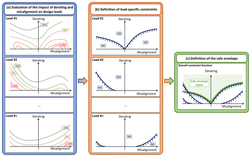
Figure 1Sketch of the process for defining the safe envelope. Left (blue) block: qualitative contour plots of the increase in all design indicators (e.g., fatigue and ultimate loads or maximum displacements) in terms of misalignment and derating. Middle (orange) block: definition of the constraint function for each indicator, i.e., derating level that compensates for the possible increase in the specific load or displacement entailed by the misalignment. Right (green) block: combination of all load-specific constraints to define the safe envelope region.
Such a process considers three consecutive steps. At first, in Sect. 2.1, a parametric analysis is performed in order to quantify the impact of the combination of yaw misalignment and derating operation on the different design loads of a wind turbine. Secondarily, from the output of the previous analysis, one has to identify the safe envelope region, i.e., the region comprising all those combinations of yaw misalignment and derating which are not associated with an increase in the design loads with respect to the reference condition with null misalignment and null derating. Finally, a load-constrained control can be formulated with the goal of finding the optimal wind farm output within the safe envelope region.
Figure 1 qualitatively illustrates this concept. At first, left plot, one evaluates the increase (or decrease) of different indicators (such as ultimate and fatigue loads as well as blade deformations) due to derated or yawed operations. Then, middle plot, for all considered indicators, the combinations of derating and yaw misalignment associated with null impact are obtained, generating multiple constraint lines. At last, right plot, all constraints are merged to define the safe envelope region, i.e., the region in the plane derating versus misalignment that satisfies all the constraints.
Clearly, to keep any turbine of the wind farm operating below or at its design loads, a wind farm controller should maximize the overall power within the safe envelope of all turbines, thereby combining derating and wake redirection.
The forthcoming Sect. 2.1 and 2.2 will better detail the definition of the misalignment–derating constraint and the load-constrained maximization of the overall wind farm output, respectively.
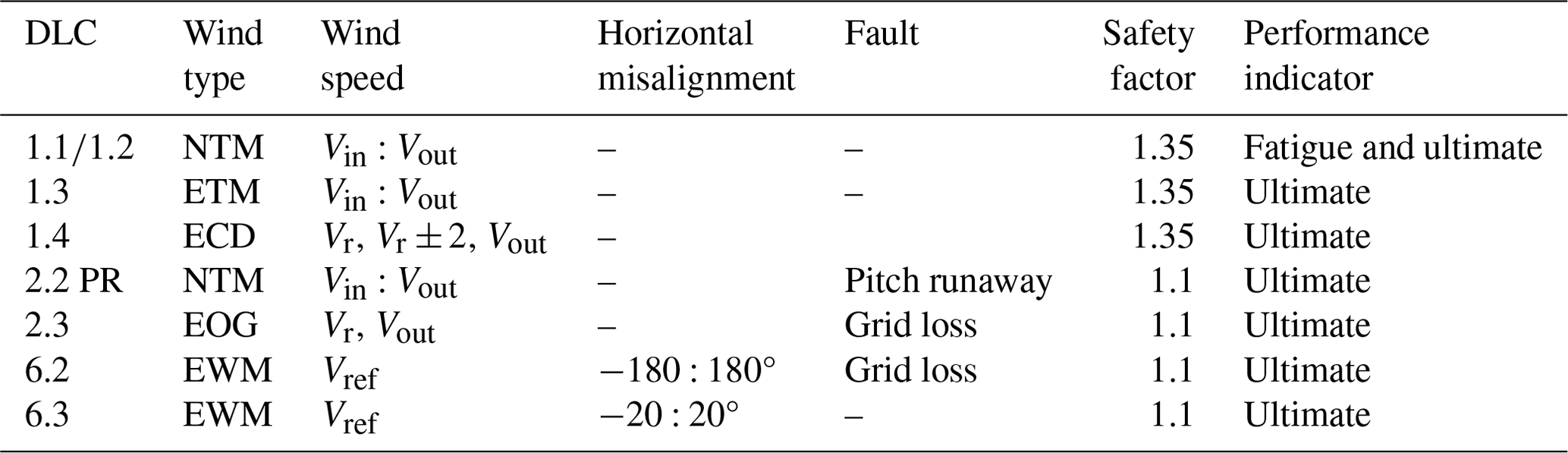
Table 1Definition of the DLCs considered in the analyses. NTM: normal turbulence model; ETM: extreme turbulence model; ECD: extreme coherent gust with direction change; EWS: extreme wind shear; EOG: extreme operating gust; EWM: extreme wind speed model.
2.1 Definition of the misalignment–derating constraint through the analysis of fatigue and ultimate loads
As already discussed in the introduction, a parametric study of the impact of derated and yawed operations on ultimate and fatigue loads and maximum blade tip deflection of the isolated wind turbine is first analyzed. The behavior of downstream machines is not considered in this work, and clearly this represents a limitation of the present analysis. The proposed approach is then to be viewed as a preliminary investigation on the possibility of combining wake redirection and derating farm control strategies to keep wind turbines operating within their load limits. The findings that will be detailed in Sect. 4 apply to the sole turbines belonging to the front row of the farm, but clearly an extension to downstream machines can be certainly done, provided that a simulator of fatigue and ultimate indicators for all turbines of the farm is available.
The parametric analysis for the isolated turbine takes into account a subset of the well-known list of design load cases (DLCs) (see IEC 61400-1 Ed.3., 2004, Sect. 7.4), reported in Table 1, chosen according to the findings of Croce et al. (2022), which highlighted the most impacting cases in terms of rotor loads of the same turbine model considered in this work, i.e., the INNWIND.EU reference 10 MW machine (Bak et al., 2013). Possible farm control failure modes are not considered within DLC2.x, because it is reasonable to think that supervisors of farm operations can be implemented so as to disengage the farm control if malfunctions are detected, in order to minimize their impact on the operations of the single turbines
The DLC list should be repeated for different couples of turbine yaw misalignment angles and derating levels.
The misalignment angle ϕ corresponds to the angle between the wind direction and the projection of the rotor axis on a horizontal plane. A positive value of the misalignment angle is, in this work, associated with a counterclockwise rotation of the rotor seen from above. Consequently, the turbine experiences positive yaw misalignment if the wind velocity, viewed by an observer located on the rotor center and looking in front of the turbine, has a lateral component coming from the right side.
The derating ξ, on the other side, is defined as the ratio between the power reduction and the reference one in the same wind condition. Accordingly,
where Pnom is the nominal power, Pder is the derated one and V is the wind velocity.
Fatigue and ultimate loads for all turbine subcomponents are then stored in look-up tables generating an overall map related to the variation of the design indicators as functions of the typical wind farm control parameters (i.e., yaw misalignment and derating).
It is expected that, independently of the turbine type and of its location within the farm, derated operations will entail a general reduction in maximum and fatigue loads. On the other side, yawed operations may increase the overall loading status of the machine with respect to the reference condition associated with null yaw misalignment and null derating. The left block in Fig. 1 provides a sketch of what one could expect from such a sensitivity analysis: all different design loads (fatigue and ultimate loads or maximum displacement) feature a complex behavior (typically non-linear and discontinuous) in terms of derating levels and misalignment angles, which can be quantified numerically.
Starting from this consideration, one can infer that given a specific load of interest, it is possible to find a derating level for each yaw misalignment angle that compensates for the possible increase in the design loads.
To this end, consider the jth generic design indicator (e.g., maximum displacement, fatigue, or ultimate load) associated with the ith turbine within the farm, named function of the turbine misalignment and derating. For all one can find a compensating derating level by imposing the equality between the design indicator and those associated with the reference condition, as
where ξi and φi are respectively the derating and misalignment angle of the ith turbine, Nturb is the number of the turbine within the farm, Nind is the number of design indicators considered, and refers to the design indicator of the reference conditions with .
The function that solves Eq. (2) is named and links the yaw misalignment angles with the load-compensating derating as
The left and middle blocks of Fig. 1 qualitatively depict this process: from the map of the increase in the interested design loads and displacements, functions of misalignment and derating, one can easily extract the constraint function seeking the null increase. Notice that each load is expected to feature different constraint functions.
Once the load-specific constraints of the ith turbine of the farm are determined for all indicators of interest, these are to be combined to define the overall turbine constraint function , by selecting the most limiting constraints for each misalignment as
The right block of Fig. 1 qualitatively shows how to combine the different load-specific constraints, into an overall one. For each turbine in the farm, the constraint function splits the domain derating–misalignment into two regions. The first one, indicated with the green texture in Fig. 1, is the safe envelope region where all combinations of derating and yaw misalignment do not entail an increase in any of the design loads and displacements with respect to the reference conditions. Such a region can be mathematically indicated as
It is expected that larger misalignment angles imply higher derating levels to compensate for possible increases in design indicators.
Then, a second region, when , comprises all combinations of misalignment and derating, where at least one load-specific constraint is violated, implying that it is possible that the ith turbine may experience an increase in that design load or displacement.
From a practical point of view, assuming that a turbine was designed and certified for standard operations with limited yaw misalignment angles, when it comes to implementing a farm control logic based on wake redirection, in order to keep the machine within its safe envelope, one has to simply enforce a certain level of derating when the turbine is subject to important yawed operations. Notice that this approach represents an interesting alternative to employing one-side wake steering policies or, in general, imposing strong limitations on the possible yaw misalignment angles, such as those used in many field applications of the wind farm control based on wake redirection (Fleming et al., 2019). In fact, it is not important to avoid a turbine working at misalignment angles potentially dangerous for its structural integrity, but rather to limit the increase in the machine loading status, a task that can be also accomplished by unloading the turbine through a suitable derating level.
Before describing possible uses of the safe envelope region within the synthesis of wind farm control, it is worthwhile clarifying some aspects.
First of all, the process described in this section to define the safe envelope region could lead to a constraint curve excessively limiting. In fact, the DLC list, which is typically employed to design turbines, also considers extreme events and faults. Consequently, operating for a limited time outside the safe envelope does not necessarily imply a structural failure of the turbine. For example, if one expects that a maximum tip deflection that is too large may be experienced at a large yaw misalignment during a coherent gust with extreme direction change (DLC 1.4), operating at that misalignment angle is not dangerous unless this extreme event happens. Clearly, such a risk is avoidable if the wind farm operator has one or more systems that allow the super-controller to measure and predict such extreme events in advance (e.g., a lidar). Moreover, the constraint curve, as it is defined in Eq. (5), applies to the turbine operations no matter the wind speed and turbulence. This fact could be limiting as the ultimate loads are typically experienced around the rated speed. Consequently, yawed operations at low speeds are seldom considered problematic. Clearly, a more thorough analysis could be performed so as to evaluate possible dependencies of the safe region with respect to wind velocity, direction and turbulence intensity. This improvement of the process, although interesting, falls outside the scope of the paper, which is aimed at proposing a possible way of combining derating and wake redirection control in a load-constrained algorithm.
That being said, the proposed combination of derating and wake redirection, even in its simplest form without wind speed and TI dependency, is less restrictive than other envelope protection alternatives, such as the one-sided wake steering, which may impose strong limitations on the misalignment angles. In fact, all potentially dangerous yaw angles do not need to be excluded but simply reached providing a suitable level of derating. It is expected that a more sophisticated definition of the safe envelope region (e.g., including speed and TI dependency) may lead to improvement in the effectiveness of the proposed solution.
2.2 Load-constrained maximization of wind farm power output based on wake redirection and derating strategies
In this section, we will consider the definition of a wind farm control based on wake steering and derating, which includes also the load constraints as defined in Eq. (5).
Three different optimal set point definitions are considered. The first refers to the classical wake redirection controller corresponding to an unconstrained optimization of the misalignment angles of all turbines in the farm for maximum overall power production. The second strategy is a constrained optimization where both misalignment angles and derating levels are optimized, while the load constraint in Eq. (5) for each turbine is enforced in the procedure. The third strategy represents a suboptimal strategy that suitably mixes the previous approaches to limit the number of optimization parameters.
2.2.1 Reference wake redirection control
Consider a generic steady-state wind farm controller based on the single wake redirection and unbounded, i.e., without considering the limitations entailed by structural issues. In this case, the control in its simplest definition consists in finding the yaw misalignment set points of all turbines belonging to the farm so as to maximize the produced power. To this end, let us collect the yaw angle ϕ of all turbines in an array Θref, as
where N is the number of turbines in the farm. Similarly, the ambient characteristics, wind speed V, turbulence intensity TI and direction ϕwind, are collected into an array p as
The optimal control set points related to the reference wake redirection strategy are computed by maximizing the overall farm power P as
where
is the overall farm power, i.e., the sum of the power of the single turbines Pi with . Clearly, the power of the single turbines Pi and, in turn, the overall farm power depend on the yaw angles of all turbines Θ and the ambient conditions p.
Equation 8) requires a non-linear optimization, usually gradient-based, with a number of optimization variables equal to the number of turbines belonging to the farm. For very large farms the optimization could be computationally expensive, especially if sophisticated simulation tools, such as those based on computation fluid dynamics, are used. For this reason, engineering or surrogate wind farm models can be employed to estimate the overall power as suggested by Doekemeijer et al. (2020) and Hulsman et al. (2020). Moreover, in order to limit the number of optimization parameters it is also possible to apply the yaw control to a limited number of turbines, for example, those which mostly affect the overall power output, as proposed by Archer and Vasel-Be-Hagh (2019).
Obviously, since no bounds for the misalignment angles have been considered, it is possible that one or more turbines experience increases in their design loads and displacements.
2.2.2 Optimal load-constrained control combining wake redirection and derating
To cope with the possible increase in loads due to misaligned operations, an optimal load-constrained control is proposed that combines derating and wake redirection, exploiting the constraint function defined in Eq. (5).
To this end, the array of optimization variables is extended by adding the derating level of all turbines, as in Θcomb,
where ξi is the derating level of the ith turbine of the farm.
The load-constrained optimal combined control set points for all machines are then computed by solving the following constrained maximization problem:
The proposed methodology has some specific advantages with respect to other control techniques developed for a similar aim. Firstly, contrary to the method considered by Hulsman et al. (2020), it does not require the construction of a surrogate model from cost-expensive CFD simulations that would also result invariably dependent on the farm configuration and on the selected scenarios employed to train the surrogate model itself. Secondarily, with respect to what was also proposed by Bossanyi (2018), we also include the ultimate loads and displacements in the analysis. In fact, the sizing of many turbine subcomponents is driven by ultimate rather than fatigue loads and, as witnessed by Croce et al. (2022) and Bottasso et al. (2014), only the modification of such ultimate indicators has an effect on the design of the system.
2.2.3 Suboptimal constrained and combined control
The solution of problem (Eq. 11) also requires the evaluation of the constraint for each wind turbine belonging to the farm and its linearization in case gradient-based optimization techniques are employed. Moreover, the number of optimization parameters is doubled with respect to that of the unconstrained problem in Eq. (8).
In order to limit the number of optimization parameters, one can employ a suboptimal algorithm that considers the load constraint in a practical and straightforward way starting from the set point obtained with the standard wake redirection control.
The idea comes from the fact that, as it will be demonstrated in Sect. 4.2, the optimal yaw misalignment angles ϕopt, solutions of problems (Eqs. 8 and 11), are similar for the majority of the analyzed cases. Along with a misalignment angle, the solution of the optimal combined problem also features a specific level of derating, which is needed to maintain the turbine operation within its safe envelope. From this consideration, one can easily devise a different set point definition that optimizes the sole misalignment angles without imposing the constraint, as it is done in the reference case object of Sect. 2.2.1. Subsequently, the level of derating for each turbine is computed a posteriori as the minimum one that is needed to satisfy the constraint in Eq. (5). It is expected that this process will generate suboptimal set points compliant with the load constraint and associated with a marginally lower increase in farm power than that associated with the optimal combined case.
To this end, one may define the array with the variable to be optimized in the suboptimal case, Θconstr, exactly as it was defined in the reference wake redirection control:
The optimal problem, as in the reference case, is formalized through an unconstrained optimization, as
which yields the suboptimal set points for all misalignment angles of all turbines.
Finally, the constraint is imposed for all turbines by finding the minimum derating level that satisfies Eq. (5), as
where is the misalignment angle of the ith turbine computed through Eq. (13), while is the related derating level, evaluated to satisfy the load constraint. Notice also that the “greater-than-or-equal-to” symbol in Eq. (5) is now substituted by a simple “equal” sign, to emphasize that the derating is computed to bring the turbine operation on the onset of its safe envelope.
In order to show what we could typically expect from the three control techniques, a qualitative plot is depicted in Fig. 2. The behavior of the control methodology, hitherto expected, will be subsequently deeply analyzed in the result section (Sect. 4). The scheme refers to a hypothetical contour plot of the increase of the overall power related to a simple two-turbine farm for a generic wind condition. The horizontal and vertical axes are associated respectively with the misalignment angle and the derating level of the upstream machine, representing the sole optimization variables, since the downstream turbine will not modify its operating condition. The contour is typically non-symmetric and may feature one or more local maxima. Moreover, levels of derating that are too high may also entail a reduction in the overall power output. As wake redirection is typically more efficient in increasing overall farm output than steady derating, the absolute maximum is expected to be found in a condition with a specific misalignment and null derating. Consequently, we may envision that the solution of the reference wake redirection problem coincides with the absolute maximum as indicated by the square marker. Clearly, this behavior depends on the specific case: as it will be shown in Sect. 4, it is possible to find the absolute maximum for non-null derating, especially when extremely reduced spacings are considered. Superimposed to the contour plot of the farm power increase, as in Fig. 2, one can draw the load constraint, emphasizing what we previously called safe envelope region (see Eq. 5). The lower bounds of the safe envelope region are reported as a solid red line. The solution of the load-constrained and combined control seeks the optimum in the upper part of the plot, where the constraint is satisfied. In general, imposing derating on the upstream machine, when it is yawed to deflect its wake out of downstream rotors, entails a reduction of the overall power output. This means that often, but not always, the optimal set point of the combined and constrained control will be found exactly on the safe envelope boundary, where the constraint is tangent to the contour line with the highest power increase. This point is marked in the plot with a circle. Finally, the suboptimal case is simply derived by projecting the solution of the reference wake redirection on the constraint, yielding the suboptimal set point in correspondence with the × marker.
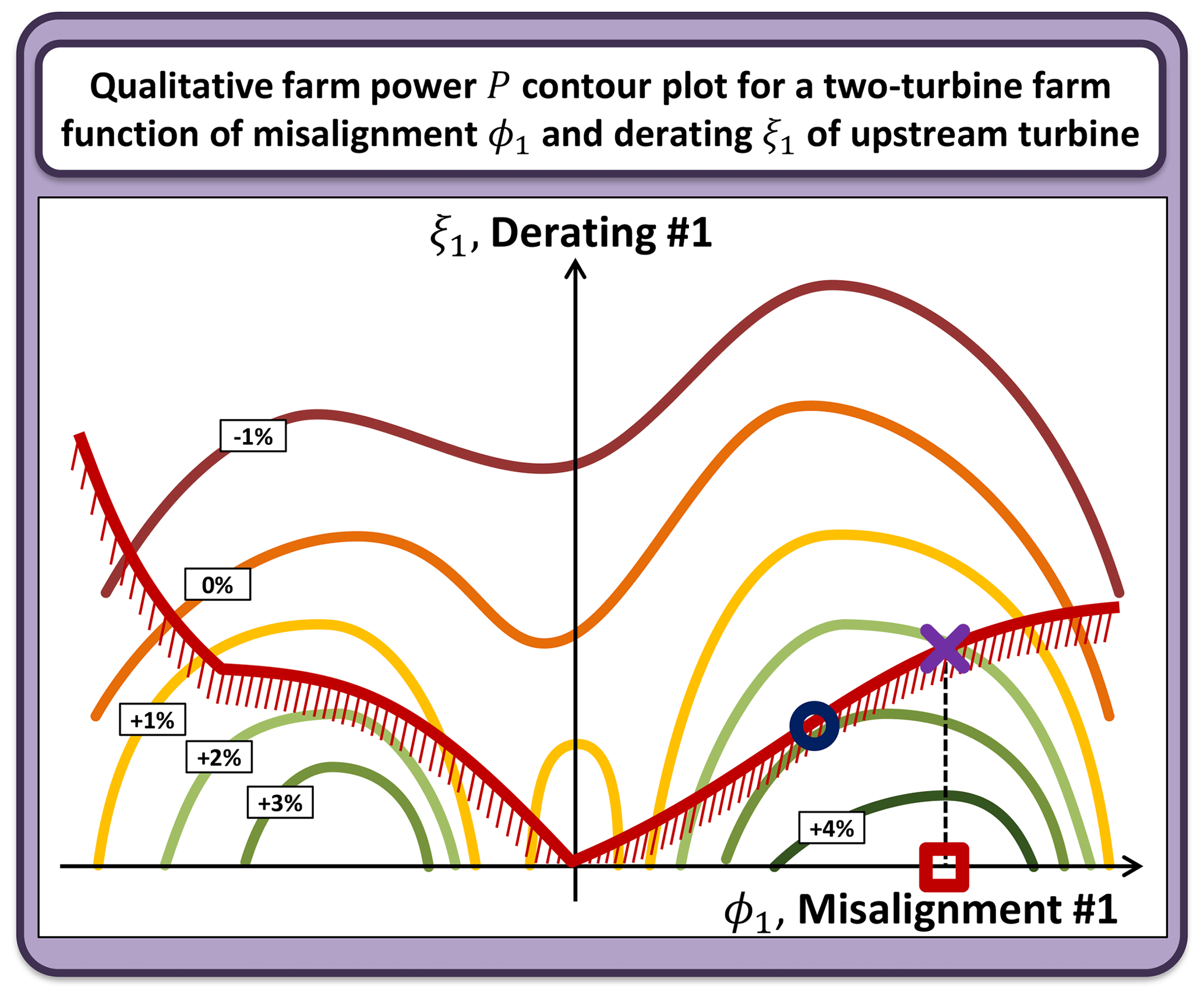
Figure 2Qualitative definition of the control set points for the three techniques in the case of a simple two-turbine farm, where only misalignment ϕ1 and derating ξ1 of the upstream turbine are optimized. Contour plot: generic increase in the overall power as a function of ϕ1 and ξ1. Solid red line: load constraint. Square marker: unconstrained optimum related to the reference wake redirection control. Circle marker: combined and constrained optimal condition. × marker: suboptimal condition.
As it will be demonstrated later on, the difference between the solution of the combined and suboptimal control is typically marginal, as well as the performance of the two techniques in terms of overall farm power increase. Hence, one could in principle define the turbine's operative set points through a simpler suboptimal algorithm without a strong detrimental impact on the overall power output.
The study object of this work considers the 10 MW INNWIND.EU model. This turbine is an upwind pitch-regulated machine of a diameter equal to about 178 m, which is described in Bak et al. (2013). The model was implemented in the general-purpose multibody software Cp-Lambda (Bottasso and Croce, 2009–2018; Bottasso et al., 2006). Turbine flexible elements, such as the blades, the tower and the shaft, are implemented through a nonlinear, kinematically exact beam formulation with fully populated cross-sectional stiffness matrices (Bauchau, 2011). Rotor aerodynamics are rendered through the classical blade element momentum theory. Lifting lines are used for modeling blade aerodynamic forces and moments, as well as for reproducing the drag of the nacelle and the tower. Hub and tip losses and tower shadow are also considered. The overall modeling of the aerodynamics implemented in Cp-Lambda was also recently validated against field data coming from a 2.3 MW wind turbine with a diameter of 80 m in sheared and yawed inflow conditions (Boorsma et al., 2023).
The turbine model considers also a first-order dynamic model for the generator and a second-order one for pitch actuators.
The control of the turbine in all operating conditions, including derated operations, is managed by the POLI-Wind controller and is based on a linear quadratic regulator (LQR), as described in Riboldi (2012) and Bottasso et al. (2012). At first, the turbine operating points can be computed from the standard Cp−λ curves as functions of the wind speed and the derating level. A linear model is extracted by linearizing the torque balance equation about all these operating points and then used within the LQR algorithm for automatically computing the control gains. Thereby, the LQR control technique automatically provides for control gains suitably scheduled for all wind speeds and all derating levels, without the need for hand-tuning.
In particular, in derated conditions, the operating point of the turbine was found by modifying only the pitch settings leaving unaltered the tip-speed ratio with respect to the nominal case at the same wind speed. Hence, for all wind speeds from the cut-in to cut-out, the pitch setting, realizing the desired derating level βderat, was found by solving the following equation:
where ρ is the air density, λnom is tip-speed ratio associated with the nominal case, β the pitch settings and Cp(λ,β) is the well-known Cp−λ look-up table. Given βderat and λnom for all desired derating levels, it is also possible to evaluate the thrust coefficients, by simply interpolating the thrust coefficient look-up table, Ct(λ,β).
Finally, misalignment angles are reproduced in the simulation by rotating the nacelle. Control architecture and gains are not modified in yawed conditions with respect to the reference, i.e., aligned, case.
Idling, faults, startup and shutdown maneuvers and, more in general, all the non-operating conditions and the transition among the different operating states are managed by the POLI-Wind Supervisor (Riboldi, 2012).
The analyzed wind farms are modeled through the software FLORIS (FLOw Redirection and Induction in Steady State), jointly developed by NREL and TUDelft (NREL, 2019). This software features a multitude of engineering wake models, which can be employed to characterize the steady flow within the farm. The turbines are included in the farm according to their power and thrust coefficients defined as functions of the wind speed. The outputs of all turbines and, in turn, the overall farm power production are computed according to the mean flow at each rotor location. In this work, the Gaussian wake model and wake combination based on kinetic energy were employed.
Within FLORIS, the impact of misalignment on wake deflection is included in the wake models, whereas derating can be rendered by modifying the power and thrust coefficients of each turbine.
In this work, we did not develop a dedicated formulation for capturing the impact of derating on wake behavior, but we simply relied on the wake model already implemented in FLORIS, which is based on the treatment of Bastankhah and Porté-Agel (2016). In such a model, the turbine thrust coefficient CT affects multiple wake characteristics including speed deficit, lateral displacement of wake center, in-wake turbulence intensity and the downstream location associated with the onset of the far-wake region. Having said this, derating a turbine indirectly affects its wake through the variation of the thrust coefficient associated with the lower power coefficient. For this reason, the Bastankhan and Porté-Agel model is considered adequate, at least for the scope of our work, to capture the combined and mutual impact of derating and misalignment on wake behavior.
Dynamical variations of wind direction, derating and misalignment are not considered.
4.1 Definition of the load constraint and of the safe envelope region
The DLC list in Table 1 was simulated with the reference 10 MW turbine model so as to evaluate fatigue and ultimate loads as well as maximum blade tip deflections for all combinations of five yaw misalignment angles (0, ±15, ±25)° and five derating levels (0 %, 2.5 %, 5.0 %, 10 %, 15 %).
Clearly, the DLC6.n series was considered only for the nominal case with null misalignment and null derating, as it refers to a non-operative phase where any farm control is not active. Since this case can result in design loads, however, it is critical to take this into account in this scenario as well. This, in general, raises another general issue regarding the impact of a wind farm controller on ultimate loads or other indicators: if design loads came from non-controlled conditions (e.g., parking) or from conditions where the wind farm control does not operate (at high winds, for example), then clearly this constitutes a condition that can allow the controller to operate without any constraints.
In this analysis, only wind farm controls scheduled with respect to the sole wind speed are considered, and an upper limit for its activation equal to 15 m s−1 is imposed, no matter the turbulence intensity (TI), as it was already done by Croce et al. (2022).
Finally, notice that the list in Table 1 refers to a selection from the whole cases prescribed by the standards (IEC 61400-1 Ed.3., 2004). In fact, only the most impacting DLCs were considered on the basis of previous analysis on the same machine, reported in detail in Croce et al. (2022).
In order to present the idea, in this paper only rotor loads are taken into account, neglecting the impact of wake redirection and derating on tower and hub loads. However, the very same process can be extended to other turbine subcomponents, without any modifications.
Figure 3 shows the two most affecting ultimate indicators related to the blade. The blade-root combined ultimate load and the maximum blade tip deflection are displayed respectively on the left and on the right. Both plots present the percentage variation of such indicators as functions of the misalignment and the derating. In order to evaluate the maximum blade tip deflection, we considered the displacements of all three blades within an azimuthal segment of 60° around the tower position, so as to capture only those conditions exposed to the risk of a blade–tower strike.
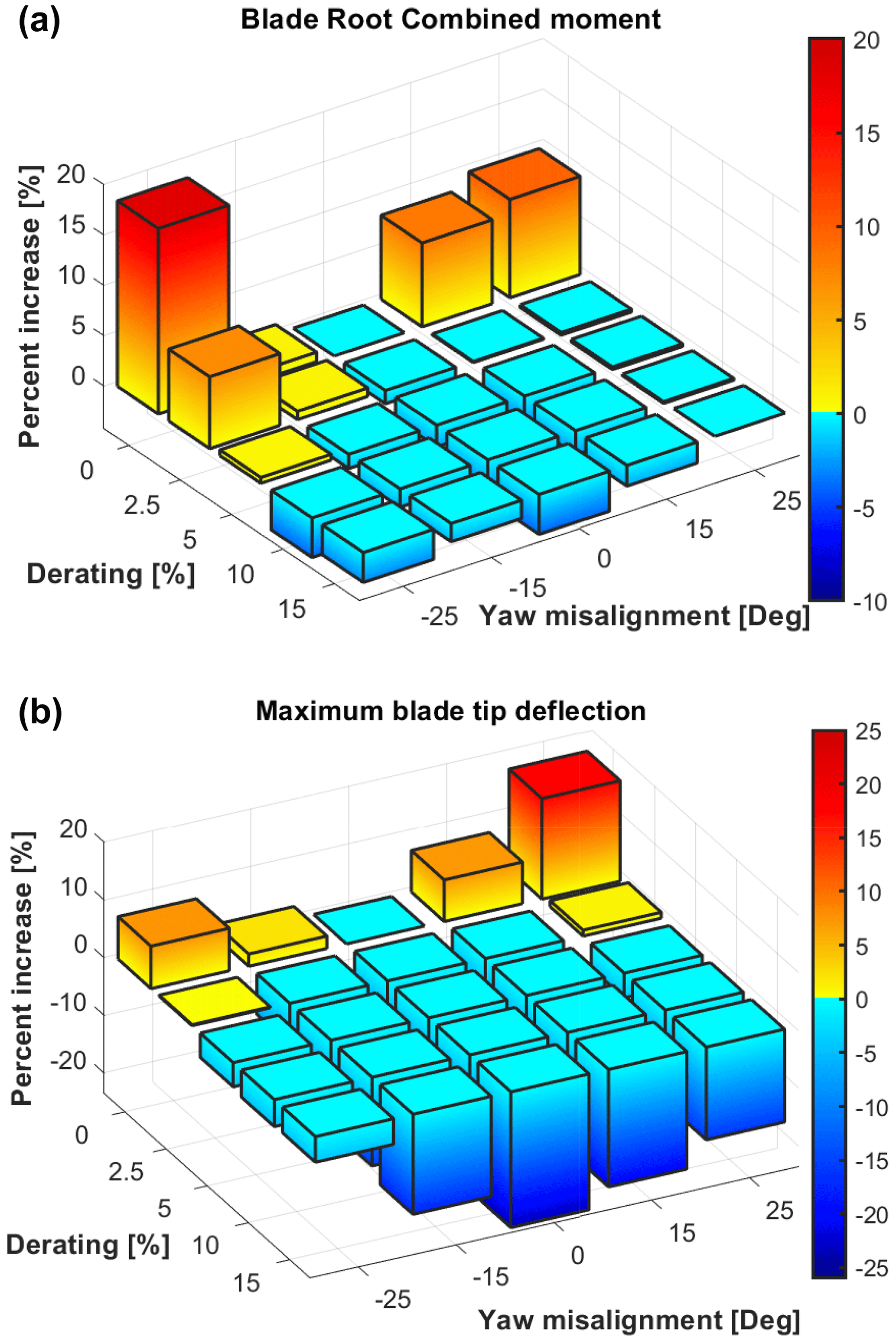
Figure 3Percentage variation of blade root combined load (a) and maximum blade tip deflection (b) as functions of misalignment and derating, taken with respect to nominal condition (i.e., null misalignment and derating).
Both plots feature similar trends: significant increases are experienced at higher misalignment angles. Furthermore, as expected, even small derating levels entail sensible reductions in the indicators, such that it is even possible to fully compensate for the increments caused by large misalignment angles. Notice also how the plots are non-symmetric as the maximum increases in blade root combined loads are experienced for negative misalignment angles, while the blade tip deflection is highest for negative ones. Quantitatively, at −25° the derating level that compensates for the increase in blade root loads is slightly higher than 5 % (see left plot of Fig. 4), whereas at +25° the increase in maximum blade deflection is compensated by a derating slightly less than 5 % (see right plot of Fig. 4). Such values are apparently limited and compatible with turbine standard operating conditions.
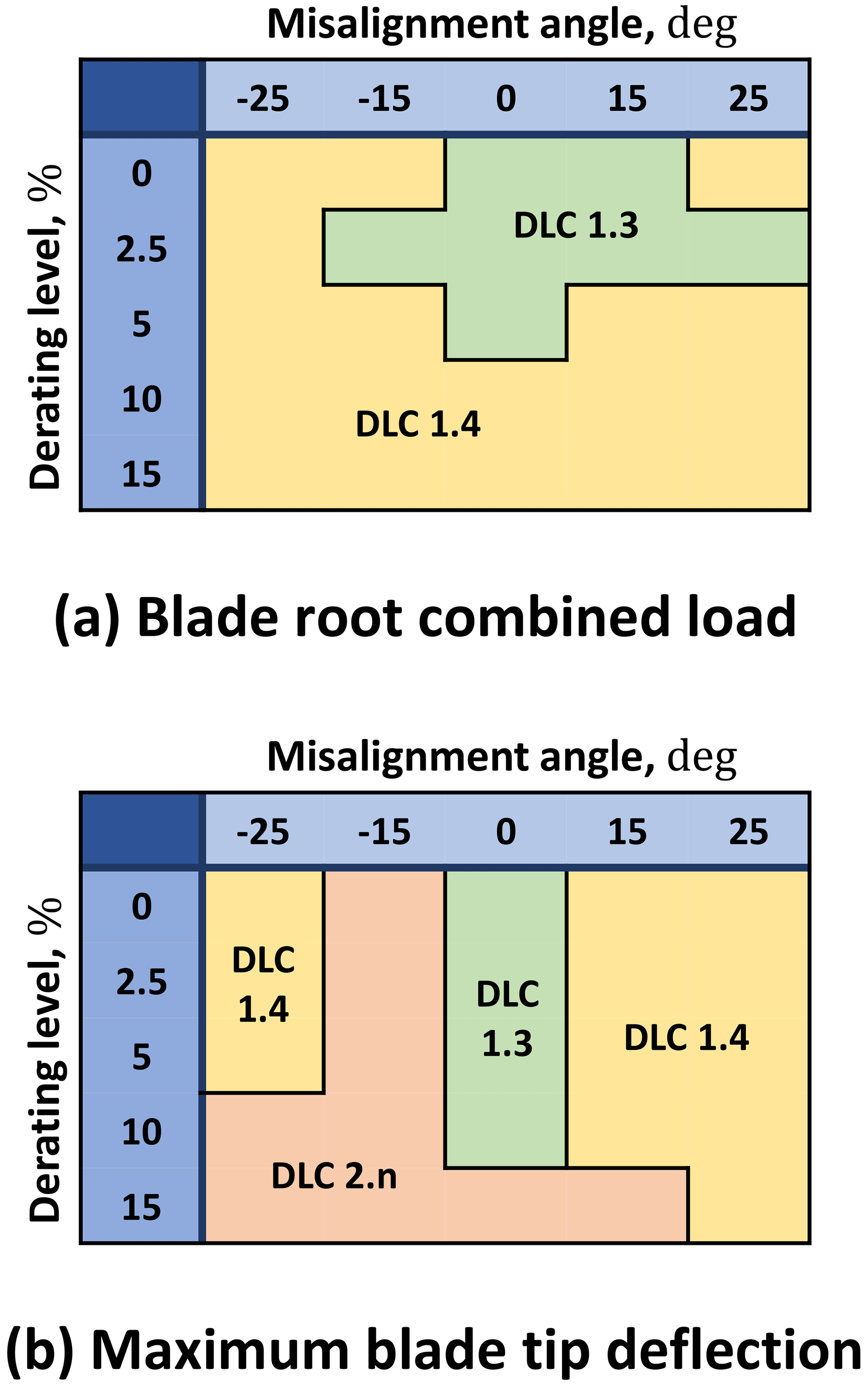
Figure 4DLC types associated with the ultimate indicators for blade root combined load (a) and maximum blade tip deflection (b) as functions of misalignment and derating.
Figure 4 shows the DLC type reporting the ultimate indicators for blade root combined load (left) and maximum blade tip deflection (right). Notice how the cases associated with ultimate loads and displacements may vary on the basis of the chosen parameters. This represents further evidence that a global overview of all operative regimes of the turbines is needed to evaluate the actual impact of the farm-controlled operations on the design drivers.
Fatigue loads, on the other side, seem less impacted by the misalignment, as can be noticed in Fig. 5 showing the cumulated DEL for blade root flapwise. The maximum percentage increase is limited, i.e., less than 2 %, and is experienced only for positive and large misalignment angles. As in the previous analyses, the positive impact of derating on loads can be clearly noticed.
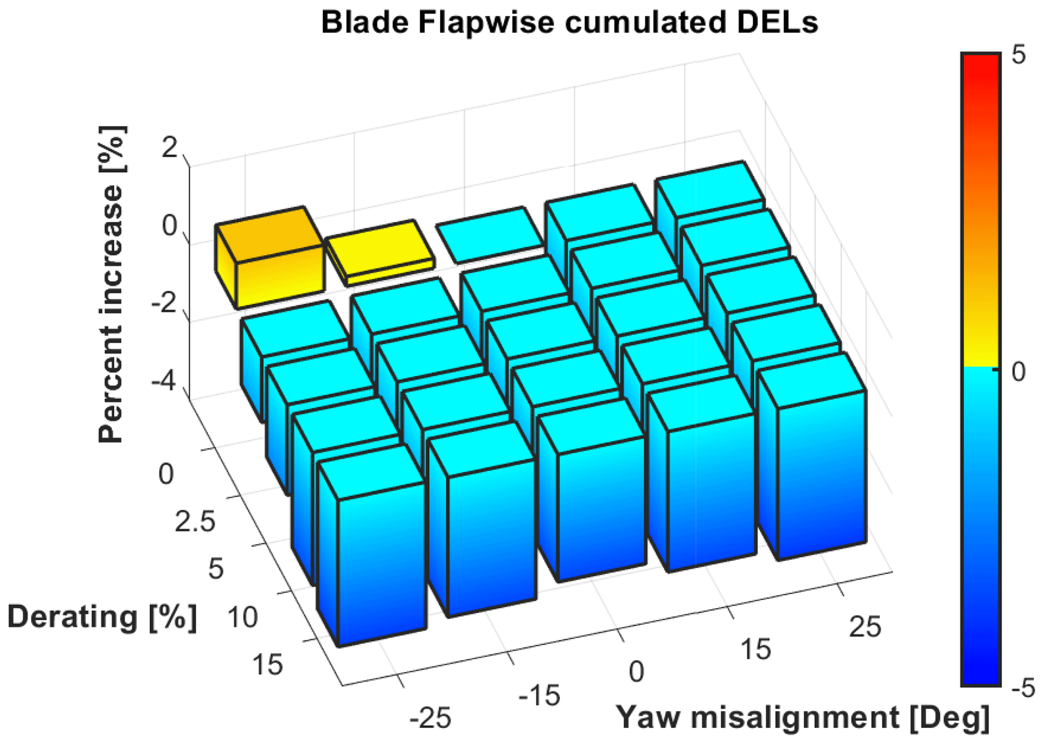
Figure 5Percentage increase in blade root flapwise fatigue load as a function of misalignment and derating, taken with respect to nominal condition (i.e., null misalignment and derating).
From the maps of the variation of the design indicators, one can easily find the specific constraint functions defined in Eq. (3) by numerically solving Eq. (2). Dealing with the solution of Eq. (2), the maps associated with loads and displacements were linearly interpolated.
Figure 6 displays the constraint functions, i.e., the derating level that compensates for the possible increase in loads and displacements induced by misalignment, for the three analyzed quantities (square markers: blade root combined ultimate load; circle markers: maximum blade tip deflection; triangle marker: blade root flapwise fatigue load).
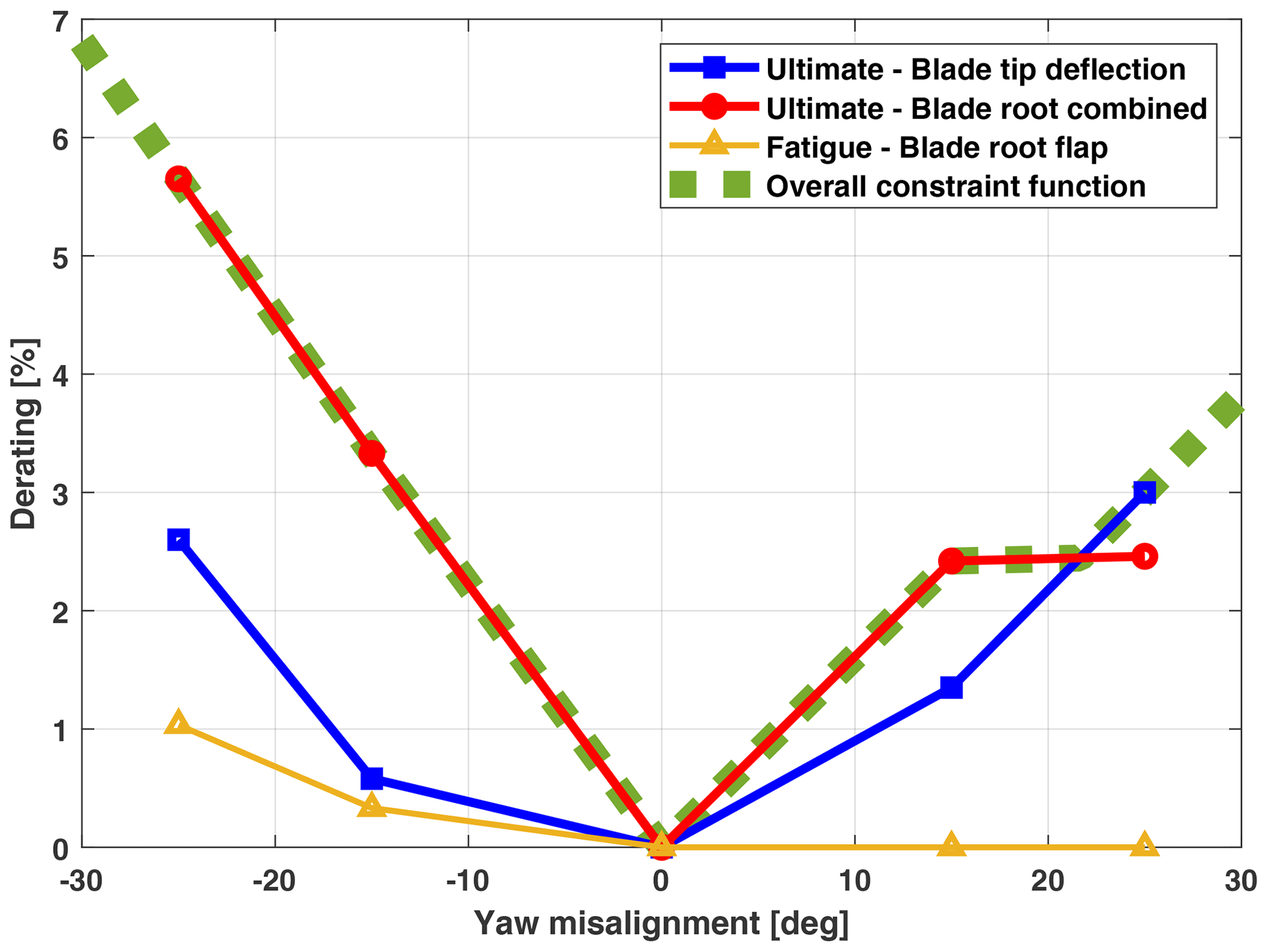
Figure 6Constraint function definition for blade root combined ultimate load, maximum blade tip deflection and blade root flapwise fatigue load.
As it can be easily seen from the graph, for this machine, the most constraining function is associated with the blade root combined ultimate load, while the fatigue of the blade root flapwise features an inactive constraint, as it is associated with lower derating levels for all misalignment angles. The constraint associated with the maximum blade tip deflection, on the other side, is active only for the highest positive misalignment angles.
Finally, the overall constraint function, visualized by a dashed thick line, can be simply extracted from load-specific constraints by taking the maximum derating level as defined in Eq. (4).
To cover the range of misalignment angles outside the bounds of the performed analyses, i.e., (±25)°, the overall constraint function was linearly extrapolated.
4.2 Optimal load-constrained farm control for different inflow conditions, spacing and overlaps
In this section, the performance of the reference, combined and suboptimal controllers is evaluated in terms of the overall power output of a simple two-turbine wind farm. The analyses were made for different inflow conditions, defined in terms of wind speed V and turbulence intensity TI, and different geometries of the farm, defined in terms of the spacing s between the turbines and the lateral offset yh of the downstream machine. Figure 7 offers an easy-to-interpret visual representation of the farm geometry parameters. In particular, we considered all combinations of the following parameters:
for a total number of 945 cases. The range of wind speed, between 7 and 14 m s−1, was chosen so as to focus on the region where the farm control is expected to be highly effective. In fact, below 7 m s−1 its impact is mild due to low speed, whereas above 14 m s−1 the control becomes ineffective as the low thrust coefficients, characterizing the upstream turbine, entail a small speed deficit inside the wake. Clearly, a comprehensive analysis for design purposes of for the evaluation of the control impact of large farms should consider a wider range, extended especially towards the cut-in speed.
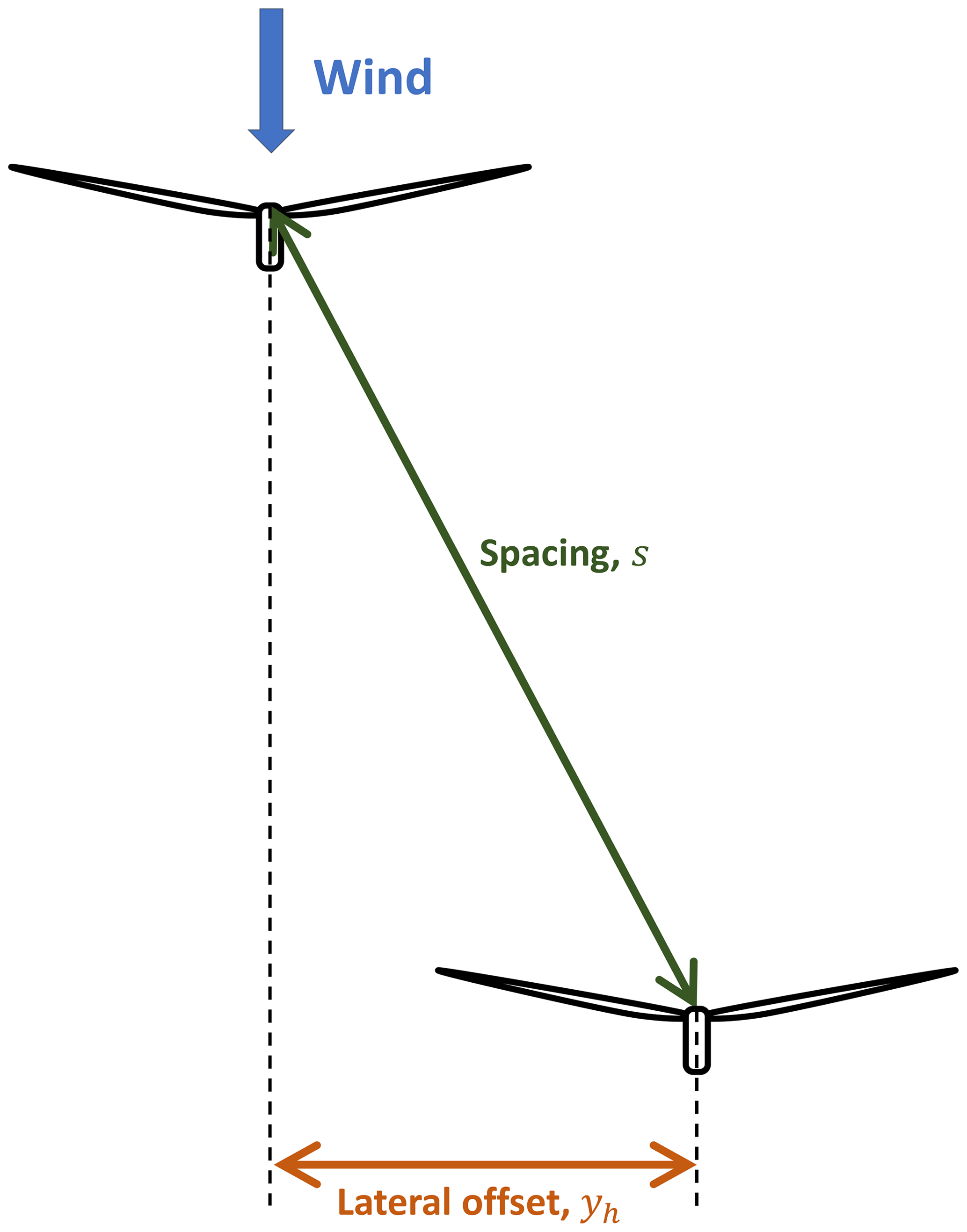
Figure 7Top view of the simple two-turbine farm with the most important geometry parameters, i.e., spacing s and lateral offset yh. The lateral offset is positive if the downstream turbine is on the right with respect to wind direction if viewed from above.
The optimal load-constrained solutions of Eq. (11) and of the suboptimal one of Eq. (13) presented here below have been computed in MATLAB, by solving the constrained optimization problem with a gradient-based algorithm (i.e., fmincon) coupled with the wind farm solver Floris (NREL, 2019).
At first, consider a reference case with wind velocity V=11.4 m s−1, corresponding to the rated speed, TI=6 %, spacing s=5 D, with D being the rotor diameter, and lateral spacing yh=0 representing a full wake impingement.
Figure 8 shows the contour plot of the farm power gain as a function of the upstream misalignment and derating. The overall constraint function, a solid red curve, is superimposed on the contour, splitting the domain into two regions, where the constraint is satisfied (i.e. the safe envelope) and where it is not. Moreover, Table 2 summarizes the control set points and the associated power gains for the three control strategies.
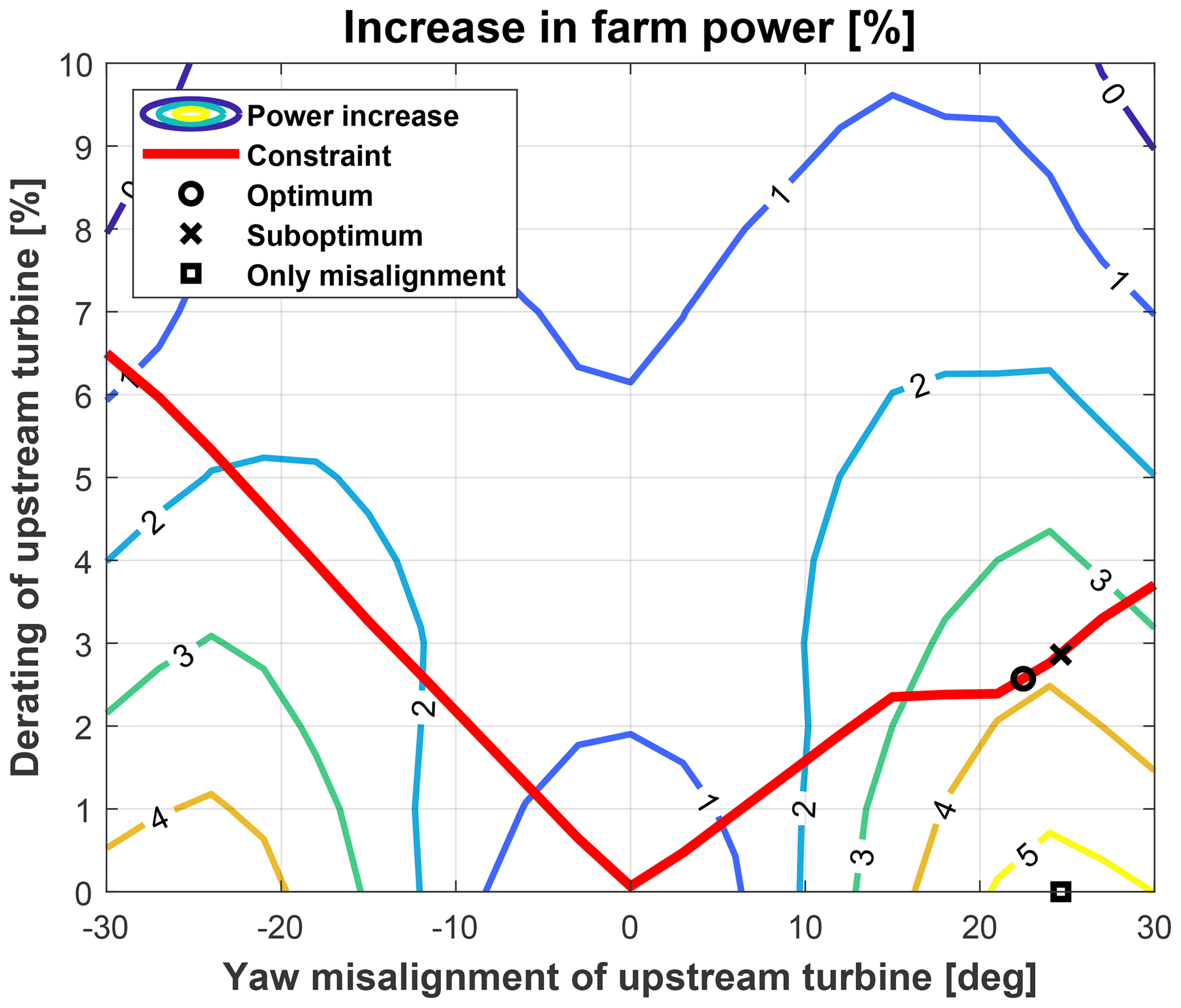
Figure 8Contour plot of the overall power output of the two-turbine farm with s=5 D, yh=0 and at V=11.4 m s−1 and TI=6 %. Solid red line represents the overall constraint function. Optimal control set points are also visualized as a square marker (reference wake redirection, only misalignment), circle marker (combined and constrained control) and × marker (suboptimal control).
Table 2Optimal set point and power gain. Two-turbine wind farm with s=5 D and yh=0 at V=11.4 m s−1 and TI=6 %.
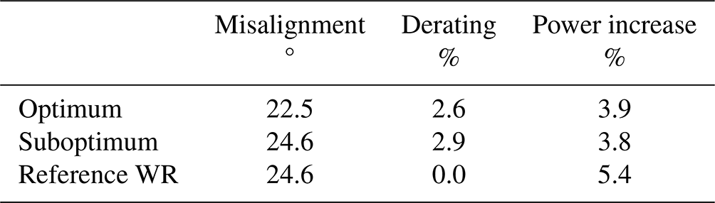
The standard unconstrained wake redirection control finds the optimum at about 24.6° and obviously with null derating, outside the safe envelope, with a net increase in the farm output of 5.4 %. The optimum found according to the combined strategy, on the other hand, features a slightly lower misalignment (i.e., 24.6°) and a mild level of derating (i.e., 2.6 %). Notice that this set point lies exactly on the constraint line. As expected, the inclusion of the constraint into the optimization strategy entails a reduction of the power gain of about 1.5 percentage points. In any case, the gain associated with the combined strategy, 3.9 %, still remains significant. Consequently, derating the upstream machine, while it is yawed, to fulfill the load constraint, reduces but does not annihilate the effectiveness of the wake redirection.
An important discussion should be made concerning the suboptimal approach. As said in Sect. 2.2.3, combined and reference wake redirection strategies typically feature similar optimal misalignment angles. This fact is clearly visible in the results shown in Fig. 8 and Table 2, providing preliminary evidence of the rationale behind the suboptimal control.
The analyzed case shows that, in the suboptimal control, the derating set point of the upstream machine (i.e., 2.9 %) is higher than that of the combined strategy as a result of the higher optimal misalignment angle. However, the gain increment in the suboptimal case (i.e., 3.8 %) appears to be only marginally lower than that of the combined control approach equal to 3.9 %. The fact that the two controls are characterized by similar performance could favor the use of the simplest strategy, the suboptimal one, especially in farms containing a large number of turbines.
Tables 3 and 4 report the optimal parameters and gains for two other cases. The first one refers to a condition with wind speed V=10.0 m s−1 and TI=6 % with spacing equal to 5 D and lateral offset equal to 0.5 D corresponding to a partial wake impingement on the left side of the downstream rotor. The second case is characterized by wind speed V=11.4 m s−1 and TI=6 % with spacing equal to 7 D and lateral offset equal to −0.5 D, corresponding now to an impingement on the right side of the downstream machine.
Table 3Optimal set point and power gain. Two-turbine wind farm with s=5 D and yh=0.5 D at V=10.0 m s−1 and TI=6 %.
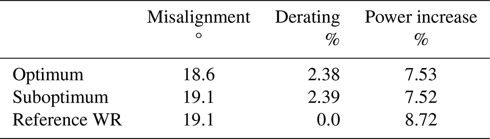
Table 4Optimal set point and power gain. Two-turbine wind farm with s=7 D and D at V=11.4 m s−1 and TI=6 %.
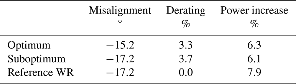
From both tables, one can immediately notice that the same conclusions that were derived for the case related to the full impingement scenario (see Fig. 8 and Table 2) are still valid. In particular, the optimal misalignment for the combined control is slightly lower in modulus than the one related to the reference wake redirection control and features a significant power gain even if lower than the one related to the unconstrained case. The difference in power gain is about 1.5 percentage points.
On the other side, suboptimal control performs similarly to the combined one, with marginally lower power gains, i.e., less than 0.2 percentage points. This last remark demonstrates again that suboptimal control represents a valuable strategy.
A last case was also considered to show how the three controllers might behave differently in extreme cases, such as those related to very tight spacing. To this end, Fig. 9 and Table 5 report the results of an analysis with a spacing s=3 D and lateral offset yh=0 at V=11.4 m s−1 and TI=6 %.
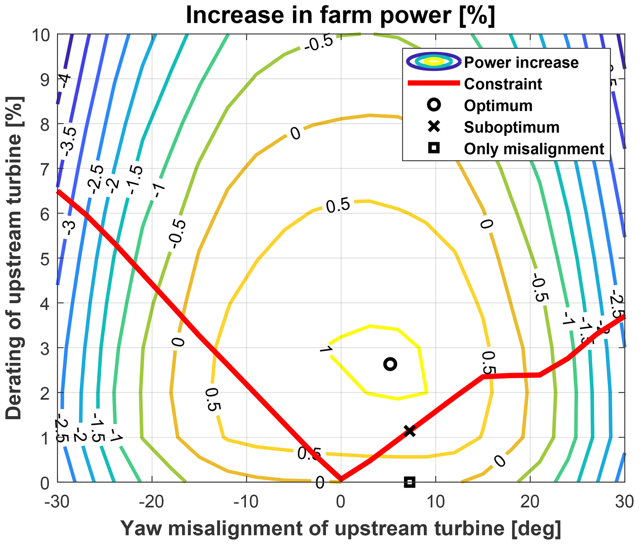
Figure 9Contour plot of the overall power output of the two-turbine farm with s=3 D and yh=0 at V=11.4 m s−1 and TI=6 %. The solid red line represents the overall constraint function. Optimal control set points are also visualized as a square marker (reference wake redirection, only misalignment), circle marker (combined and constrained control), and × marker (suboptimal control).
Table 5Optimal set point and power gain. Two-turbine wind farm with s=3 D and yh=0 at V=11.4 m s−1 and TI=6 %.
In this case, the pure wake redirection is not as effective as in the previous conditions as the close spacing between the turbine does not allow the wake to actually move away from the downstream rotor. Derating strategy, on the other hand, appears to be more effective. In this extreme situation, the optimal combined control outperforms the standard wake redirection and features optimal misalignment angles noticeably lower, i.e., from 7.2 to 4.6°. As a consequence of that, the differences in the performance between combined and suboptimal controls are quite evident.
Clearly, especially for all unusual cases such as the previous example with 3 D spacing, a question arises over the validity of the employed steady wake model and the impact of derating on wake characteristics. In fact, it is well-known that steady wake modeling may overestimate the impact of the variation of axial induction on wake development. This said, the obtained increase in power output associated with derating, even in this rather extreme case, does not deviate too far from wind tunnel or field test observations (Kim et al., 2016; van der Hoek et al., 2019; Bossanyi and Ruisi, 2021; Campagnolo et al., 2023).
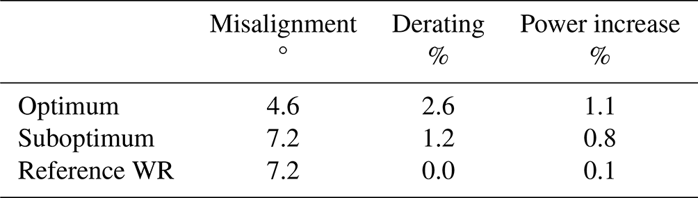
An overall analysis of the differences in the performance of the three controls, considering the whole set of 945 analyzed conditions, was also performed with the aim of analyzing this procedure applied to this specific wind farm in more detail. Figure 10 displays the histograms representing the number of occurrences associated with specific differences in terms of power gain between the reference wake redirection and the optimal combined controls, on the left, and between combined and suboptimal controls, on the right. The number of occurrences is reported in the y axis, while the difference in the power gains is in the x axis.
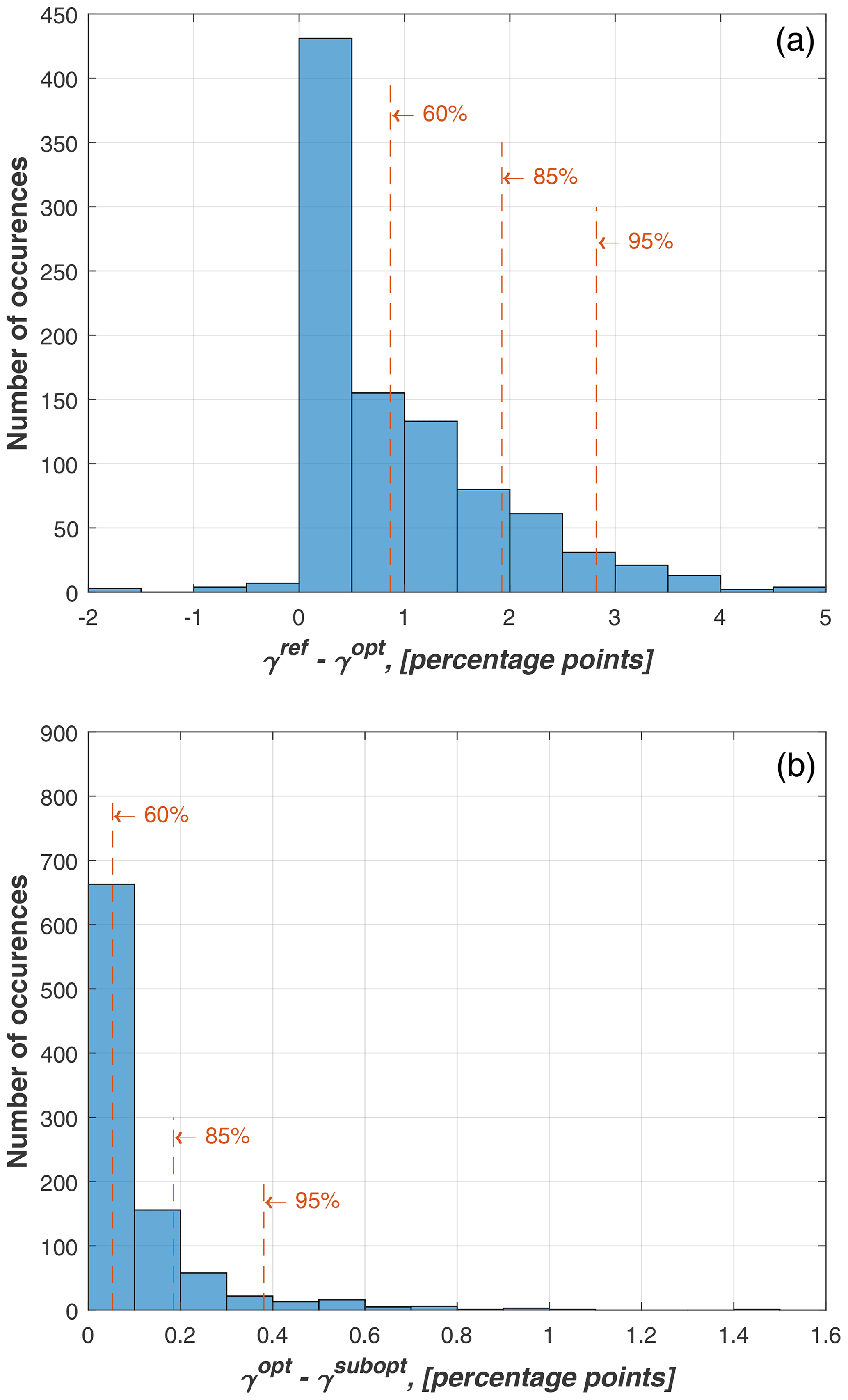
Figure 10Histograms representing the number of occurrences associated with the differences between the power gains of the three control strategies. (a) Difference between the percentage gain associated with reference wake redirection control γref and that related to the optimal combined one γopt. (b) Difference between the percentage gain associated with the optimal combined control γopt and that related to the suboptimal one γsubopt. Vertical dashed lines indicate the range associated with 60 %, 85 % and 95 % of the occurrences.
From the left plot of Fig. 10, it is possible to verify that the overall impact of the load constraint on the power output is in general limited, as the difference between the percentage gain associated with reference control γref and that related to the combined one γref is quite limited for the majority of the analyzed cases. As indicated by the vertical dashed lines, the difference between the gains of the two strategies is below 0.8 percentage points for 60 % of the cases, below 2 percentage points for 85 % of the cases, and below 2.75 percentage points for 95 % of the cases. Negative values in the x axis of the left plot in Fig. 10 refer to those extreme conditions with spacing equal to 3 D, for which the optimal combined control outperforms the reference one.
The difference between combined and suboptimal controls is even less marked, as witnessed by the right plot of Fig. 10. For 95 % of the cases, the power gain of the suboptimal control is lower than that of the combined one for at most 0.4 percentage points.
4.3 Evaluation of control performance for a nine-turbine wind farm
In order to evaluate the robustness of the controls described in Sect. 2.2, in a more realistic scenario, a nine-turbine farm is considered. The goal of the present example is to simply verify that the increased number of optimization variables and the introduction of the constraints do not lead to a problem that is difficult to resolve as the number of turbines grows.
The farm layout is organized such that the farm is square-shaped with three rows and three columns spaced by 5 D. The farm is also oriented so as to have the diagonals aligned in the north–south and east–west directions, respectively. The direction the wind is blowing from is indicated by ϕwind. When ϕwind=0° the wind is blowing from the north, whereas when ϕwind=90° it is blowing from the east.
The wind farm layout is represented in Fig. 11, where also the turbine numbering is reported.
Two relevant conditions are considered. The first considers and inflow with speed and direction ϕwind=0°, i.e., coming from the north. The second one refers to the same speed but to a different direction, ϕwind=45°, representing the most impacting condition, being associated with minimum distance between upstream and downstream rotors and with full impingement levels.
In this analysis, it is assumed that the constraint function stays the same for all turbines, independently of the location within the farm, as
Notice that, when the wind is coming from the north, the inner wind turbine (WT) 5 is inside the wake of WT 1 and influences through its wake the performance of WT 9. Hence, it is both waked and performing a control action. The hypothesis in Eq. (17) for this turbine (and similarly for any inner turbine) should then be carefully evaluated. We expect that for fatigue loads the assumption of free-stream flow is strong but can be acceptable for the evaluation of the ultimate loads and displacements that, in the case at hand, represent the active constraints.
Tables 6 and 7 display the results of the two analyses, reporting, along with the turbine-specific and overall power gains, the derating and the misalignment angle of all machines, for all controls.
Table 6Wind farm analysis at V=9 m s−1 and ϕwind=0°. ϕi and ξi: misalignment angle in ° and derating level of the i turbine; γ: overall farm power gain in percentage. The behavior of WT 4, WT 7 and WT 8 is respectively equal to that of WT 2, WT 3 and WT 6. The performance of WT 8 is equal to that of WT 6.
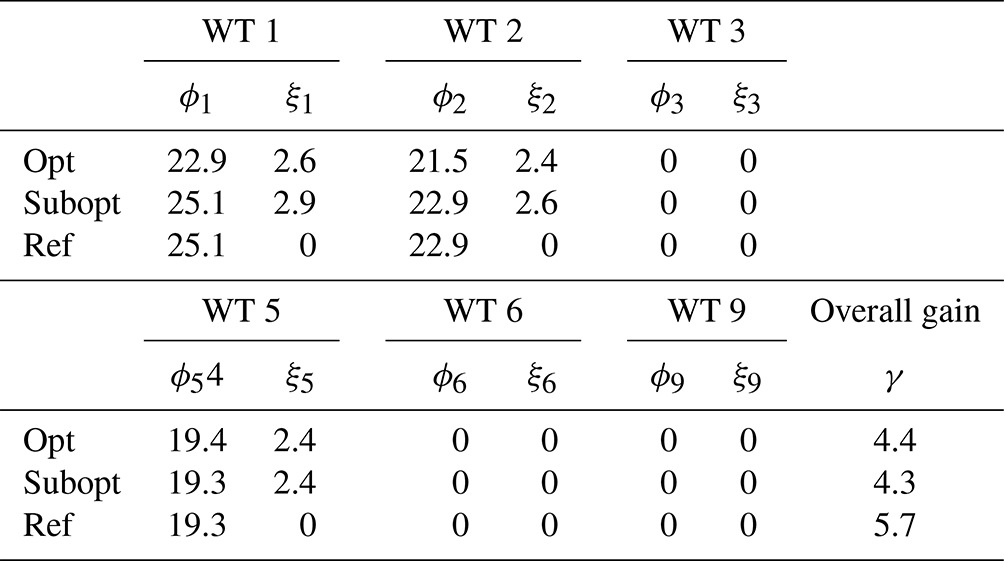
Table 7Wind farm analysis at V=9 m s−1 and ϕwind=45°. ϕi and ξi: misalignment angle in ° and derating level of the i turbine; γ: overall farm power gain in percentage. The behavior of WT 2 and WT 3 is equal to that of WT 1. The behavior of WT 5 and WT 6 is equal to that of WT 4. The behavior of WT 8 and WT 9 is equal to that of WT 7.
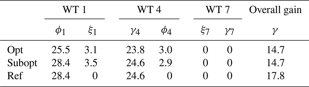
From the results obtained considering the nine-turbine wind farm, one can derive the same conclusions related to the simpler cases, analyzed in Sect. 4.2. In particular, the optimal combined control features lower optimal misalignment in the upstream turbines than those associated with the reference control. The inclusion of the load constraint entails a mild reduction in the optimal farm output, without, in any case, jeopardizing the effectiveness of the wake redirection strategy. Finally, the performance of the suboptimal control is similar to that of the optimal combined one, with a negligible reduction in the gain potentially achievable.
In this paper, we first presented a parametric analysis related to the impact of the combination of derating and misalignment angles on the design indicators (i.e., fatigue and ultimate loads, maximum displacements) of an isolated multi-MW wind turbine. The parametric analysis, thanks to the fact that derating entails a general reduction in the loading status of the turbine, was then used for deriving a safe envelope region, i.e., a region where the combination of the two parameters is not associated with an increase in any of the machine design indicators. The safe envelope can be easily formulated in terms of the minimum derating level needed to compensate for possible increases in design indicators due to yawed operations. From the performed analyses, such compensating derating was expressed as a nonlinear function of the sole misalignment angle, neglecting possible dependencies on wind speed and turbulence intensity.
Finally, two novel wind farm control techniques, based on a combination of wake redirection and derating, are proposed. The main idea is to exploit a combined use of derating and misalignment to optimize farm production while maintaining all the turbines in the farm within the respective save envelope region.
In a combined approach, the turbine operation set points, in terms of derating and misalignment, are defined so as to maximize the farm power subject to the constraint that the operation of all turbines be inside the safe envelope. In a suboptimal approach, the load constraint is directly imposed on the optimal misalignment angles defined by the standard wake redirection control.
The entire procedure, from the computation of the safe envelope region to the definition of the load-constrained controls, was tested in a simulation environment using a 10 MW reference turbine model and two simple reference farms, made by two and nine turbines.
From the results shown in this paper, as well as from extensive practice on the same topic, the following conclusions can be derived.
-
Derating the turbine when it is yawed has the advantage of reducing the impact that misaligned operations may have on turbine design indicators. In particular, not only blade fatigue loads are reduced but also ultimate loads and maximum blade tip deflections.
-
With a simple parametric study, it is possible to find a derating level, function of the misalignment angles, that is able to compensate for the possible increase in the design indicators entailed by the yawed operations. In this study, the obtained compensating derating levels were quite small, of the order of a few percentage points.
-
When tested on simple two-turbine and nine-turbine farms, the optimal combined control performs as expected. Clearly, a penalty of a few percentage points in the power gain is experienced as a result of the imposition of the load constraint. However, the optimal combined farm control remains highly effective in increasing the overall power output.
-
With extremely low spacing, i.e., 3 D, the optimal combined control outperforms the standard wake redirection. This was due to the fact that for such reduced spacing the derating is more effective than the wake redirection technique.
-
The suboptimal control, interestingly, features a performance in terms of overall power gain, really similar to that of the optimal combined control, and requires an optimization with fewer variables.
-
With the proposed controls it could no longer be necessary to limit the yaw misalignment angle of the upstream turbine or to employ “one-sided wake steering” methodology to limit the impact on loads due to large yaw operations. The “derating versus misalignment” constraint automatically ensures that the turbine operates within its load limits.
Clearly, the work object of this paper represents a preliminary investigation, and much still needs to be done before this technique reaches maturity.
The most important improvement of the analysis deals with the tuning of the steady wake model. Even if the farm power output increases, obtained in the present analyses, do not significantly differ from the expectation based on the current literature, it is certainly possible that different wake parameters or different turbine types could lead to quantitatively different results. However, a dramatic loss of effectiveness of the load-constrained combined control is not expected in different scenarios.
In terms of extension of the proposed control strategy, one can easily list multiple opportunities.
Firstly, the definition of the safe envelope region should include a dependency on wind speed and, possibly, turbulence intensity. This may improve the effectiveness of the optimal combined control, which, as it is implemented in this work, considers the load constraint also at low speeds, which are typically associated with a minor impact on the loading status of the machine.
Secondarily, it will also be important to include in the formulation fatigue and ultimate loads of the downstream machines. In fact, the constraint function was here computed only for the upstream turbine in out-of-wake conditions. This will be investigated in further research activities.
Moreover, we considered only rotor loads and displacement in the definition of the safe envelope. One should also evaluate the constraints related to other measurements such as tower and hub moments.
Last, the proposed methodology, with a few modifications in the tools used, may be employed to further analyze the combination of other wind farm control techniques (i.e., dynamic induction controls).
Finally, the inclusion of the proposed controls in a turbine design framework is certainly an extension of interest.
All the aforementioned extensions and possibilities are currently under investigation.
All figures and corresponding numerical data are available for download at https://doi.org/10.5281/zenodo.10959098 (Croce et al., 2024). The linked MATLAB–Python tool implementing the combined controls can be made available upon request.
All authors provided fundamental inputs to this work through discussions, feedback and analyses of the obtained results. AC and SC devised the main idea of the load-constrained controls and wrote the manuscript. AC supervised the research activities. FI performed the Floris analyses.
At least one of the (co-)authors is a member of the editorial board of Wind Energy Science. The peer-review process was guided by an independent editor, and the authors also have no other competing interests to declare.
Publisher's note: Copernicus Publications remains neutral with regard to jurisdictional claims made in the text, published maps, institutional affiliations, or any other geographical representation in this paper. While Copernicus Publications makes every effort to include appropriate place names, the final responsibility lies with the authors.
The authors gratefully acknowledge Gianluca Dadda for his contribution to the preparation of the multibody aero-servo-elastic simulations of the design load cases for the reference 10 MW wind turbine combining wake redirection and derating.
This paper was edited by Jan-Willem van Wingerden and reviewed by Daan van der Hoek and one anonymous referee.
Annoni, J., Gebraad, P. M., Scholbrock, A. K., Fleming, P., and v. Wingerden, J.-W.: Analysis of axial-induction-based wind plant control using an engineering and a high-order wind plant model, Wind Energy, 19, 1135–1150, 2016. a
Archer, C. L. and Vasel-Be-Hagh, A.: Wake steering via yaw control in multi-turbine wind farms: Recommendations based on large-eddy simulation, Sustain. Energ. Technol. Assess., 33, 34–43, https://doi.org/10.1016/j.seta.2019.03.002, 2019. a
Bak, C., Zahle, F., Bitsche, R., Kim, T., Yde, A., Henriksen, L. C., Hansen, M. H., Blasques, J. P. A. A., Gaunaa, M., and Natarajan, A.: The DTU 10-MW Reference Wind Turbine Project Site, Tech. rep., DTU, https://orbit.dtu.dk/en/publications/the-dtu-10-mw-reference-wind-turbine (last access: 17 May 2024), 2013. a, b
Bastankhah, M. and Porté-Agel, F.: Experimental and theoretical study of wind turbine wakes in yawed conditions, J. Fluid Mech., 806, 506–541, https://doi.org/10.1017/jfm.2016.595, 2016. a
Bauchau, O. A.: Flexible Multibody Dynamics, in: vol. 176 of Solid Mechanics and Its Applications, 1st Edn., Springer Netherlands, ISBN 978-94-007-0334-6, e-ISBN 978-94-007-0335-3, https://doi.org/10.1007/978-94-007-0335-3, 2011. a
Boorsma, K.: Power and loads forwind turbines in yawed conditions — Analysis of field measurements and aerodynamic predictions, Tech. Rep. ECN-E–12-047, ECN – Energy reserach Center of the Netherlands, https://publications.tno.nl/publication/34629178/y56dz3/e12047.pdf (last access: 17 May 2024), 2012. a
Boorsma, K., Schepers, G., Aagard Madsen, H., Pirrung, G., Sørensen, N., Bangga, G., Imiela, M., Grinderslev, C., Meyer Forsting, A., Shen, W. Z., Croce, A., Cacciola, S., Schaffarczyk, A. P., Lobo, B., Blondel, F., Gilbert, P., Boisard, R., Höning, L., Greco, L., Testa, C., Branlard, E., Jonkman, J., and Vijayakumar, G.: Progress in the validation of rotor aerodynamic codes using field data, Wind Energ. Sci., 8, 211–230, https://doi.org/10.5194/wes-8-211-2023, 2023. a
Bortolotti, P., Bottasso, C. L., and Croce, A.: Combined preliminary–detailed design of wind turbines, Wind Energ. Science, 1, 71–88, https://doi.org/10.5194/wes-1-71-2016, 2016. a
Bossanyi, E.: Combining induction control and wake steering for wind farm energy and fatigue loads optimisation, J. Phys.: Conf. Ser., 1037, 032011, https://doi.org/10.1088/1742-6596/1037/3/032011, 2018. a, b
Bossanyi, E. and Ruisi, R.: Axial induction controller field test at Sedini wind farm, Wind Energ. Sci., 6, 389–408, https://doi.org/10.5194/wes-6-389-2021, 2021. a
Bottasso, C., Croce, A., Nam, Y., and Riboldi, C.: Power curve tracking in the presence of a tip speed constraint, Renew. Energy, 40, 1–12, https://doi.org/10.1016/j.renene.2011.07.045, 2012. a
Bottasso, C., Campagnolo, F., and Croce, A.: Multi-disciplinary constrained optimization of wind turbines, Multibod. Syst. Dynam., 27, 21–53, https://doi.org/10.1007/s11044-011-9271-x, 2022. a
Bottasso, C. L. and Croce, A.: Cp-Lambda user manual, Tech. rep., Dipartimento di Scienze e Tecnologie Aerospaziali, Politecnico di Milano, Milano, Italy, http://www.poliwind.polimi.it/ (last access: 17 May 2024), 2009–2018. a
Bottasso, C. L., Croce, A., Savini, B., Sirchi, W., and Trainelli, L.: Aero-servo-elastic modeling and control of wind turbines using finite element multibody procedures, Multibod. Syst. Dynam., 16, 291–308, 2006. a
Bottasso, C. L., Croce, A., Riboldi, C. E. D., and Salvetti, M.: Cyclic pitch control for the reduction of ultimate loads on wind turbines, J. Phys.: Conf. Ser., 524, 012063, https://doi.org/10.1088/1742-6596/524/1/012063, 2014. a
Campagnolo, F., Tamaro, S., Mühle, F., and Bottasso, C. L.: Wind Tunnel Testing of Combined Derating and Wake Steering, 22nd IFAC World Congress, IFAC-PapersOnLine, 56, 8400–8405, https://doi.org/10.1016/j.ifacol.2023.10.1034, 2023. a
Croce, A., Cacciola, S., and Sartori, L.: Evaluation of the impact of active wake control techniques on ultimate loads for a 10 MW wind turbine, Wind Energ. Sci., 7, 1–17, https://doi.org/10.5194/wes-7-1-2022, 2022. a, b, c, d, e, f
Croce, A., Cacciola, S., Montero Montenegro, M., Stipa, S., and Praticó, R.: A CFD-based analysis of dynamic induction techniques for wind farm control applications, Wind Energy, 26, 325–343, https://doi.org/10.1002/we.2801, 2023. a
Croce, A., Cacciola, S., and Isella, F.: Figures and data: Combining wake redirection and derating strategies in a load-constrained wind farm power maximization, Zenodo [data set], https://doi.org/10.5281/zenodo.10959098, 2024. a
Damiani, R., Dana, S., Annoni, J., Fleming, P., Roadman, J., van Dam, J., and Dykes, K.: Assessment of wind turbine component loads under yaw-offset conditions, Wind Energ. Sci., 3, 173–189, https://doi.org/10.5194/wes-3-173-2018, 2018. a, b, c
Debusscher, C. M. J., Göçmen, T., and Andersen, S. J.: Probabilistic surrogates for flow control using combined control strategies, J. Phys.: Conf. Ser., 2265, 032110, https://doi.org/10.1088/1742-6596/2265/3/032110, 2022. a
Doekemeijer, B. M., van der Hoek, D., and van Wingerden, J.-W.: Closed-loop model-based wind farm control using FLORIS under time-varying inflow conditions, Renew. Energy, 156, 719–730, https://doi.org/10.1016/j.renene.2020.04.007, 2020. a
Doekemeijer, B. M., Kern, S., Maturu, S., Kanev, S., Salbert, B., Schreiber, J., Campagnolo, F., Bottasso, C. L., Schuler, S., Wilts, F., Neumann, T., Potenza, G., Calabretta, F., Fioretti, F., and van Wingerden, J.-W.: Field experiment for open-loop yaw-based wake steering at a commercial onshore wind farm in Italy, Wind Energ. Sci., 6, 159–176, https://doi.org/10.5194/wes-6-159-2021, 2021. a
Fleming, P., King, J., Dykes, K., Simley, E., Roadman, J., Scholbrock, A., Murphy, P., Lundquist, J. K., Moriarty, P., Fleming, K., van Dam, J., Bay, C., Mudafort, R., Lopez, H., Skopek, J., Scott, M., Ryan, B., Guernsey, C., and Brake, D.: Initial results from a field campaign of wake steering applied at a commercial wind farm – Part 1, Wind Energ. Sci., 4, 273–285, https://doi.org/10.5194/wes-4-273-2019, 2019. a, b, c
Frederik, J. A., Weber, R., Cacciola, S., Campagnolo, F., Croce, A., Bottasso, C., and van Wingerden, J.-W.: Periodic dynamic induction control of wind farms: proving the potential in simulations and wind tunnel experiments, Wind Energ. Sci., 5, 245–257, https://doi.org/10.5194/wes-5-245-2020, 2020. a
Gebraad, P., Thomas, J. J., Ning, A., Fleming, P., and Dykes, K.: Maximization of the annual energy production of wind power plants by optimization of layout and yaw-based wake control, Wind Energy, 20, 97–107, 2017. a
Gebraad, P. M. O., Teeuwisse, F. W., van Wingerden, J. W., Fleming, P. A., Ruben, S. D., Marden, J. R., and Pao, L. Y.: Wind plant power optimization through yaw control using a parametric model for wake effects – a CFD simulation study, Wind Energy, 19, 95–114, https://doi.org/10.1002/we.1822, 2016. a
Germanischer Lloyd: Part IV – Rules and Guidelines Industrial Services, 1 Guideline for the Certification of Wind Turbines, Edition 2010, Germanischer Lloyd Industrial Services GmbH, Hamburg, Germany, https://www.dnv.com/publications/the-new-guideline-for-the-certification-of-wind-turbines-edition (last access: 17 May 2024), 2010. a
Howland, M. F., Lele, S. K., and Dabiri, J. O.: Wind farm power optimization through wake steering, P. Natl. Acad. Sci. USA, 116, 14495–14500, https://doi.org/10.1073/pnas.1903680116, 2019. a
Hulsman, P., Andersen, S. J., and Göçmen, T.: Optimizing wind farm control through wake steering using surrogate models based on high-fidelity simulations, Wind Energ. Sci., 5, 309–329, https://doi.org/10.5194/wes-5-309-2020, 2020. a, b
Kim, H., Kim, K., Paek, I., Bottasso, C. L., and Campagnolo, F.: A Study on the Active Induction Control of Upstream Wind Turbines for total power increases, J. Phys.: Conf. Ser., 753, 032014, https://doi.org/10.1088/1742-6596/753/3/032014, 2016. a
IEC 61400-1 Ed.3.: Wind Turbines – Part 1: Design requirements, Tech. rep., Garrad Hassan and Partners Ltd, St Vincent's Works, Silverthorne Lane, Bristol, UK, 2004. a, b, c
Meyers, J., Bottasso, C. L., Dykes, K., Fleming, P., Gebraad, P., Giebel, G., Göçmen, T., and van Wingerden, J.-W.: Wind farm flow control: prospects and challenges, Wind Energ. Sci., 7, 2271–2306, https://doi.org/10.5194/wes-7-2271-2022, 2022. a, b
NREL – National Renewable Energy Laboratory: FLORIS. Version 3.0, GitHub [code], https://github.com/NREL/floris (last access: 17 May 2024), 2019. a, b, c
Riboldi, C. E. D.: Advanced control laws for variable-speed wind turbines and supporting enabling technologies, PhD thesis, Politecnico di Milano, https://hdl.handle.net/10589/56887 (last access: 17 May 2024), 2012. a, b
van der Hoek, D., Kanev, S., Allin, J., Bieniek, D., and Mittelmeier, N.: Effects of axial induction control on wind farm energy production – A field test, Renew. Energy, 140, 994–1003, https://doi.org/10.1016/j.renene.2019.03.117, 2019. a