the Creative Commons Attribution 4.0 License.
the Creative Commons Attribution 4.0 License.
Brief communication: Real-time estimation of the optimal tip-speed ratio for controlling wind turbines with degraded blades
Devesh Kumar
Mario A. Rotea
Rotor performance is adversely affected by the wear and tear of blade surfaces caused, for example, by rain, snow, icing, dirt, bugs and aging. Blade surface degradation changes the aerodynamic properties of the rotor, which in turn changes the optimal tip-speed ratio (TSR) and the corresponding maximum power coefficient. Below the rated wind speed, if a turbine continues to operate at the manufacturer-designed optimal TSR, the rotor power could decrease more than necessary unless the optimal TSR is corrected to compensate for blade degradation or blade surfaces are restored. Re-tuning the tip-speed ratio can lead to an improvement in energy capture without blade repairs. In this work, we describe a real-time algorithm to re-tune the tip-speed ratio to its optimal but unknown value under blade degradation. The algorithm uses power measurements only and the Log-Power Proportional-Integral Extremum Seeking Control (LP-PIESC) strategy to re-tune the TSR. The algorithm is demonstrated in simulations to command the set-point TSR required by a generator speed control loop that maximizes power at below-rated wind speeds. Comparison of this solution with a baseline controller that uses the optimal TSR for a rotor with clean blades demonstrates improvements in energy capture between 0.5 % and 3.4 %, depending on the severity of blade degradation and the wind conditions. These results are obtained using the OpenFAST simulation tool, the National Renewable Energy Laboratory (NREL) 5 MW reference turbine and the NREL-developed Reference Open-Source Controller (ROSCO).
- Article
(4131 KB) - Full-text XML
- BibTeX
- EndNote
Below the rated wind speed, a wind turbine is typically controlled to maximize the power extracted from the wind. In this regime, the rotor power is proportional to the power available in the wind times the power coefficient (CP). For a typical variable-speed, variable-pitch wind turbine, CP is a unimodal function of the tip-speed ratio (TSR; λ) and the blade-pitch angle (β) (Manwell et al., 2010; Burton et al., 2011). This implies that there is an optimal tip-speed ratio and blade-pitch angle for maximizing CP and hence the output power. Intuitively, maximizing power at below-rated wind speeds requires keeping the blade-pitch angle constant at its ideal value βopt while adjusting the rotor speed to maintain the optimal tip-speed ratio λopt despite wind speed changes (Pao and Johnson, 2011; Burton et al., 2011; Abbas et al., 2022).
Rotor performance is adversely affected by the wear and tear of blade surfaces caused, for example, by rain, snow, icing, dirt, bugs and aging. Blade surface degradation changes the aerodynamic properties of the rotor, which in turn changes the optimal tip-speed ratio λopt and the corresponding maximum power coefficient . If a turbine continues to operate at the originally designed λopt, the rotor power can decrease more than necessary unless the optimal tip-speed ratio is corrected to compensate for blade degradation. Re-tuning the optimal tip-speed ratio in these off-design conditions can lead to an improvement in energy capture.
Annual energy production (AEP) losses due to blade degradation have been reported in the literature. For example, Han et al. (2018) showed that contamination and erosion at the leading edge of blade tips can reduce AEP by 2 %–3.7 %. Ehrmann et al. (2013, 2017) and Wilcox et al. (2017) studied the effect of surface roughness on wind turbine performance. Ehrmann et al. (2013) observed that roughness leads to a consistent increase in drag compared to a clean configuration. Ehrmann et al. (2017) showed that the maximum lift-to-drag ratio decreases 40 % for 140 µm roughness, corresponding to an approximate 2.3 % loss in AEP. AEP losses of 4.9 % and 6.8 % for National Advisory Committee for Aeronautics (NACA) 633-418 and National Renewable Energy Laboratory (NREL) S814 airfoils, respectively, operating with 200 µm roughness were observed in Wilcox et al. (2017). Wilcox and White (2016) studied the power loss due to insect contamination on the blades. They concluded that insect impingement simulations should be considered in airfoil design. A numerical approach capable of simulating the ice accretion transient phenomenon and its effects on wind turbine performance was presented in Zanon et al. (2018). This reference shows that keeping the tip-speed ratio at its designed optimal value can reduce the power coefficient by 3 % after the icing event.
In this brief communication we attempt to answer the following question: can re-tuning control parameters recover power/AEP losses before blade repairs are made? This question is considered in the context of torque control systems that use optimal values of TSR to calculate the set point for the generator angular speed that maximizes power.
In principle, online methods to estimate the power coefficient can be useful to answer this question. Due to space limitations, we do not elaborate on these methods. Instead, we provide references to such literature. See, for example, the work of Odgaard et al. (2008), De Kooning et al. (2013) and Petković et al. (2013).
In this work, we explore the use of a recently develop variant of extremum-seeking control (ESC) for re-tuning control parameters to maximize power capture for rotors with degraded aerodynamic performance. More specifically, we apply the Log-Power Proportional-Integral Extremum Seeking Control (LP-PIESC) algorithm to identify the optimal tip-speed ratio (TSR) for contaminated or eroded blades in real time. This algorithm requires one measurement only, i.e., the rotor power. The LP-PIESC algorithm has been shown to be a faster variant of the traditional perturbation-based ESC (Kumar and Rotea, 2022).
The LP-PIESC algorithm is used to identify optimal-TSR set points to be tracked by a generator speed control loop operating at below-rated wind speeds. Due to its widespread availability, we have chosen the Reference Open-Source Controller (ROSCO) developed by Abbas et al. (2022) and the NREL 5 MW reference turbine model (Jonkman et al., 2009) to illustrate our approach.
The use of extremum-seeking control to identify optimal control parameters for a single wind turbine is not new; an early reference is Creaby et al. (2009), followed by work using large-eddy simulations in Ciri et al. (2017) and an experimental campaign in Xiao et al. (2019). Due to the lack of consistent convergence across different wind speeds of the standard ESC, the log-power extremum-seeking control (LP-ESC) was introduced in Rotea (2017) to have predictable consistent convergence time and to produce an algorithm that after calibration at one single wind speed exhibits the same performance at all below-rated wind speeds. LP-ESC was then tested using high-fidelity simulations to demonstrate its advantages over the conventional ESC in Ciri et al. (2019).
The organization of the paper is as follows. The main characteristics of ROSCO are given in Sect. 2. This section also describes the specific blade degradation cases considered (contamination and erosion) and gives a brief description of the LP-PIESC algorithm. This algorithm has two distinct (but coupled) functions. The control function, which is described in Sect. 2, and a parameter estimation function, whose main features are given in Appendix A. Section 3 focuses on the real-time identification of the optimal tip-speed ratio with the LP-PIESC algorithm. To facilitate the paper's readability, the algorithm parameters and the most relevant equations for parameter estimation are provided in Appendix A. The results of simulations using OpenFAST (NREL, 2020) for several wind profiles are given in Sect. 3. These results provide numerical evidence that the LP-PIESC algorithm can find the unknown optimal tip-speed ratio despite variations in the mean wind speed, turbulence intensity and level of blade degradation, thus increasing energy capture in off-design conditions. Conclusions are given in Sect. 4.
2.1 Reference Open-Source Controller (ROSCO)
The Reference Open-Source Controller (ROSCO) has been introduced in Abbas et al. (2022) to update the legacy NREL 5 MW controller (Jonkman et al., 2009). ROSCO is available for download and implementation on GitHub at https://github.com/NREL/ROSCO (NREL, 2021). This controller is proposed as a modern control architecture that can be deployed on multiple wind turbine models and simplifies the tuning procedure in OpenFAST (NREL, 2020). In this architecture, both the generator torque (τg) and the blade-pitch angle (β) are governed by PI controllers. The set-point tip-speed ratio (λsp) is a tunable parameter required to determine the generator speed reference value. Using the set-point tip-speed ratio and estimated wind speed (), a generator speed reference (ωg,ref) is obtained from Eq. (1).
where R is the rotor radius and N is the gear ratio. The generator speed reference ωg,ref is the reference input to the generator torque PI controller for generator speed (ωg) control to maximize the power capture at below-rated wind speeds. Details of the ROSCO framework can be found in Abbas et al. (2022).
In this work, we tune the set-point tip-speed ratio λsp in the ROSCO controller using the LP-PIESC algorithm to maximize the power capture at below-rated wind speeds. We did not modify the control logic of ROSCO and used it as it is defined for the NREL 5 MW reference turbine in OpenFAST. In our simulations, ROSCO takes the wind speed estimate from the rotor disk average (RtVAvgxh) calculated by OpenFAST. We do not use the wind speed estimator in ROSCO because this estimator makes use of parameters that could change with blade degradation or contamination. Recent methods with the potential to provide accurate estimates of the wind speed despite changes in blade properties are in Lio et al. (2021), and these require real-time turbine time series to develop a wind speed estimator using a Gaussian process regression approach. A more expensive alternative would be using lidar as done in Meng et al. (2022). We have not pursued any of these methods because our study is meant to provide evidence of the potential the LP-PIESC algorithm has to estimate unknown parameters such as the optimal TSR despite uncertainty in turbine parameters; see also Kumar and Rotea (2022), where the LP-PIESC algorithm is used to tune the torque gain and blade-pitch angle to optimal values, starting from non-optimal parameters.
2.2 Performance loss due to leading-edge blade degradation
Rotor performance is adversely affected by the wear and tear of blade surfaces caused, for example, by rain, snow, icing, dirt, bugs and aging. Blade surface degradation changes the aerodynamic properties of the rotor, which in turns changes the manufacturer-designed optimal tip-speed ratio (λopt) and the corresponding maximum power coefficient (). If a turbine continues to operate at the designed λopt, the rotor power can decrease more than necessary unless the optimal tip-speed ratio (TSR) is corrected to compensate for blade degradation. Re-tuning the tip-speed ratio in these off-design conditions can lead to an improvement in energy capture. In this article we provide numerical evidence demonstrating that extremum-seeking control can re-tune the TSR to its new optimal value.
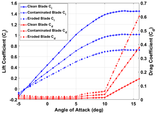
Han et al. (2018) studied the impact on annual energy production of blade leading-edge contamination and erosion. In particular, they studied the aerodynamic performance of the blade tip airfoil (NACA64) for the NREL 5 MW wind turbine (Jonkman et al., 2009). To demonstrate the ability of the LP-PIESC algorithm for finding the optimal TSR for rotors with degraded blades, we selected two cases from Han et al. (2018): (i) contamination of blades, which decreased the lift coefficient (Cl) by 30 % and increased the drag coefficient (Cd) by 150 %, and (ii) erosion of blades, which decreased the lift coefficient (Cl) by 50 % and increased the drag coefficient (Cd) by 300 %. These changes in the lift and drag coefficients occur at an angle of attack (AoA) between −5 to 16°. Note that the NACA64 airfoil is in the tip region of the NREL 5 MW turbine blade and is approximately 30 % of the blade length. A schematic with the degraded-blade sector is in Fig. 1. The lift and drag coefficients for the clean blade as well as the contaminated and eroded blades are shown in Fig. 2.

Figure 1Tip section of the NREL 5 MW blade with the NACA64 airfoil. It is 30 % of the blade length, 43.05 m from the blade root to 61.5 m.
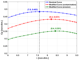
The CP–λ curves with degraded blades were obtained from NREL OpenFAST (NREL, 2020) using the modified lift and drag coefficients. Figure 3 shows the results for all the cases. Note that the designed optimal values for a clean blade are λopt=7.6 and . The modification of the lift and drag coefficients leads to a shift in the optimal CP–λ curve. When the blade is contaminated, the optimal TSR increases to λopt=8.2, with . For the eroded blade, the curve shift is more pronounced and the maximum power coefficient drops to at λopt=8.4. We can observe from these plots that if the turbine is still controlled using the clean-blade set point for both the contaminated and degraded blade, it will produce less power than the maximum power it could produce were the set-point TSR to be changed to its new optimal values. The CP loss would be roughly 1.4 % for the contaminated blade and 3.5 % for the eroded blade if the TSRs are not re-tuned. Thus, it is advantageous to change the set-point TSR to the new optimal values. In this study, the LP-PIESC algorithm is used to search for these new optimal tip-speed ratios.
2.3 Log-Power Proportional-Integral Extremum Seeking Control (LP-PIESC)
In this study, we use the Log-Power Proportional-Integral Extremum Seeking Control (LP-PIESC) strategy introduced in Kumar and Rotea (2022). The algorithm is gradient-based, which can adjust the tunable parameters to maximize a system's performance index in real time without detailed physical models. The use of the log of power (LP) as a feedback signal enables consistent convergence across varying mean wind speeds (Rotea, 2017; Ciri et al., 2019), and PIESC achieves rapid convergence to the optimum (Guay and Dochain, 2017).
Let us assume that we seek the value of the scalar parameter u (tip-speed ratio) that maximizes a scalar-valued function f(u) (power). To solve this problem, the proportional-integral extremum-seeking controller proposed in Guay and Dochain (2017) has been modified to add a back-calculation anti-windup and is given by Eq. (2):
where sat(⋅) is a linear function between a TSR of 4 and 10, kp is the proportional gain, τI is the integral time constant, kb is the anti-windup gain and is a scalar parameter to be estimated. This parameter is representative of the derivative of the log of power with respect to the change in tip-speed ratio. A sinusoidal dither signal is chosen and is denoted by d. In comparison to the more popular version of extremum seeking (Krstić and Wang, 2000), which is essentially the integrator equation in Eq. (2) for , the proportional term accelerates convergence. The difference between the saturated output us and the calculated controller output u is fed back into the input of the integrator through an anti-windup gain kb, which is similar to the design of the anti-windup ESC proposed in Creaby et al. (2009). Intuitively, the addition of the proportional term increases the control bandwidth (speed of response) that results when substituting a pure integral controller with a PI control law.
The strategy utilized to find the unknown time-varying parameter also contributes to convergence time improvements and is discussed in Appendix A. This approach is not the conventional perturbation–demodulation method used to extract gradient information in previous versions of ESC (Krstić and Wang, 2000). Rather, it draws inspiration from continuous-time recursive least squares with forgetting as well as estimation of time-varying parameters and adaptive control (Guay and Dochain, 2017; Krstić et al., 1995; Shaferman et al., 2021).
As mentioned already, blade surface degradation changes the aerodynamic properties of the rotor, which results in shifting of the manufacturer-designed optimal TSR. Therefore, real-time identification of the modified optimal TSR for degraded blades is needed to the avoid loss of energy. The LP-PIESC algorithm can be used to do an online search of the modified optimal TSR in real time.
3.1 LP-PIESC design
This subsection provides the basic block diagram of a turbine equipped with the LP-PIESC algorithm for optimal-TSR estimation. The algorithm itself is described in detail in Eq. (2) and Appendix A. The latter also contains a description of the tuning of parameters in the LP-PIESC algorithm.
3.1.1 System architecture
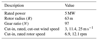
The NREL 5 MW turbine reference model with OpenFAST is used in this work (Jonkman, 2013). Table 1 lists the major parameters of this turbine model.
This study considers a wind turbine operating at below-rated wind speeds, as this is the region where wind turbine control algorithms seek to maximize power. A high-level block diagram of the entire system is shown in Fig. 4. The input to the LP-PIESC algorithm is the logarithm of the rotor power P normalized with respect to the rated power Pr=5 MW after a moving-average filter is applied to the instantaneous power signal to remove high-frequency fluctuations. The output of the LP-PIESC algorithm is the estimate of the set-point tip-speed ratio (us). A rate limit of 0.1 s−1 is applied to the estimated set-point tip-speed ratio to produce the actual set-point TSR (λsp) for the ROSCO controller (as in Eq. 1).
The LP-PIESC parameters (Eq. 2 and Appendix A) are designed using a clean blade (no contamination or erosion) and then fixed at these design values for implementation with the degraded-blade cases. First the most relevant dynamics is identified using step responses to select dither frequency and amplitude. Then, the remaining parameters of the LP-PIESC algorithm are calibrated by trial and error to achieve convergence to the optimal TSR for the clean blade at 8 m s−1 wind speed and with 10 % turbulence intensity. To maintain continuity in the exposition, the equations for the LP-PIESC parameter estimation methods and the numerical values for all the algorithm parameters can be found in Appendix A.
3.2 Results
3.2.1 Simulation conditions
The LP-PIESC controller with the parameters shown in Table A1 of Appendix A is evaluated with OpenFAST simulations for hub-height mean wind speeds of 7, 8 and 9 m s−1; for a vertical shear exponent α=0.2; and under turbulence intensities of 10 % and 15 %, respectively.
The wind profiles for the simulations were obtained using NREL TurbSim (Jonkman, 2009). TurbSim follows International Electrotechnical Commission (IEC) 61400-1 (IEC, 2005) to generate the wind profiles. We specified five parameters in the TurbSim input file to generate the wind input files for our simulations. (1) The turbulence model chosen is Kaimal (IECKAI). (2) The IEC turbulence type is set as the Normal Turbulence Model (NTM). (3) The hub height is 90 m for the NREL 5 MW reference turbine. (4) The mean wind speed is input. (5) The turbulence intensity is in percentage. All other parameters were left to their default values in TurbSim. The mathematical expression for the Kaimal spectrum can be found in IEC (2019).
Figure 5 illustrates the time series of the hub-height wind speeds with means of 7, 8 and 9 m s−1 and 10 % turbulence intensity (TI). We use these wind profiles to evaluate the performance of the LP-PIESC algorithm for both the contaminated-blade case and the eroded-blade case (from Sect. 2.2). We also simulate cases with 15 % TI and the same mean values. In all simulations, we set the set-point tip-speed ratio in ROSCO at the clean-blade optimum, i.e., , for the first 500 s of the simulation and then turn on the LP-PIESC algorithm to evaluate the convergence of the set-point TSR to the new optimal values for contaminated and eroded blades, respectively.
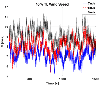
Figure 5Wind speed (velocity, V) time series at hub height: mean wind speeds of 7, 8 and 9 m s−1 and 10 % turbulence intensity.
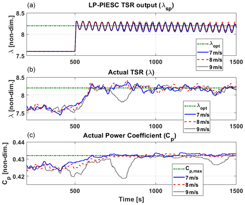
Figure 6Contaminated-blade performance of the LP-PIESC algorithm with the parameters in Table A1 and hub-height wind speed from Fig. 5. The LP-PIESC algorithm is turned on at 500 s. Rate-limited LP-PIESC set-point tip-speed ratio λsp (a). Tip-speed ratio λ (b) and estimated power coefficient CP (c) from the OpenFAST output file. The horizontal dashed green lines indicate true optimal parameters λopt and CP,max (Fig. 3).
3.2.2 Simulation results
Results for the contaminated blade with the wind profile in Fig. 5 are shown in Fig. 6. The top plot shows the set-point tip-speed ratio (λsp) given to ROSCO (see Fig. 4), the middle plot shows the actual tip-speed ratio (λ) output and the estimated power coefficient (CP) is shown in the bottom plot; these latter two parameters are from OpenFAST. Both the tip-speed ratio (λ) and the power coefficient (CP) time series are shown after applying a 100 s moving-average filter to the OpenFAST outputs to smooth these signals. Recall from Fig. 3 that the optimal value of the tip-speed ratio and the maximum value of CP for this case are 8.2 and 0.431, respectively.
The LP-PIESC algorithm converges to the new optimal tip-speed ratio almost instantaneously for all the cases. The actual tip-speed ratio (λ) and the estimated power coefficient (CP) converge in less than 100 s. With 9 m s−1 mean wind speed there are some drops in the estimated power-coefficient (CP) around 500, 800 and 1400 s. From Fig. 5, we can see that during those instances the wind speed moves into above-rated operation of the NREL 5 MW turbine (Jonkman et al., 2009). This can also be seen from Fig. 7 where the blade pitch (bottom right plot) is activated at those times to regulate the generator speed close to its rated value of 1173.7 rpm. The increase to above-rated wind speed and approximate regulation of generator speed provided by ROSCO explain the dips observed in the power coefficient and tip-speed ratio in Fig. 6.
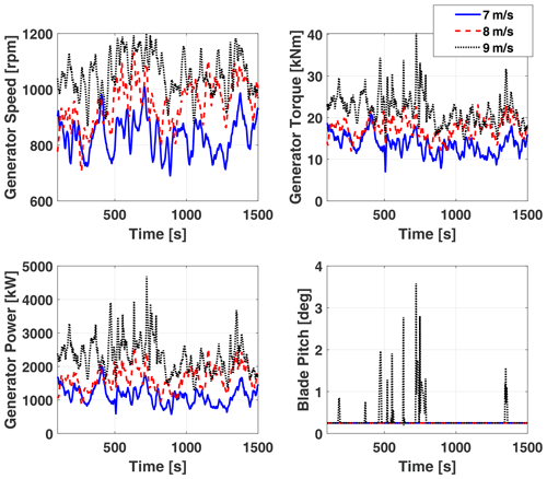
Figure 7Contaminated-blade response of turbine parameters with the LP-PIESC algorithm and the wind profiles in Fig. 5.
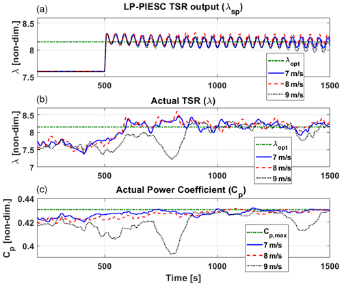
Figure 8Contaminated-blade performance of the LP-PIESC algorithm with the parameters shown in Table A1 and wind input with 15 % TI. The LP-PIESC algorithm is turned on at 500 s. Rate-limited LP-PIESC set-point tip-speed ratio λsp (a), tip-speed ratio from the OpenFAST output λ (b), estimated power coefficient CP (c). The horizontal dashed green lines indicate true optimal parameters λopt and CP,max (Fig. 3).
We also evaluate the performance of the LP-PIESC algorithm with an increased turbulence intensity of 15 %. The simulation results are shown in Fig. 8. It is observed that increasing the turbulence intensity does not affect the transient or steady-state performance of the LP-PIESC algorithm. The LP-PIESC algorithm continues to converge quickly, and the drop in CP for 9 m s−1 wind speed is due to the turbine entering the above-rated wind speed region.
Next, we evaluate the performance of the LP-PIESC algorithm for the eroded-blade case using the same mean wind speeds and turbulence intensity as before. Recall from Fig. 3 that the optimal value of the tip-speed ratio and the maximum value of CP for this case are 8.4 and 0.351, respectively. Results for this case are shown in Figs. 9 and 10. It can be observed that as the LP-PIESC algorithm is turned on at 500 s, it converges to the optimal tip-speed ratio almost instantaneously for all the cases. The drops in CP for 9 m s−1 mean wind speed can be explained as before.
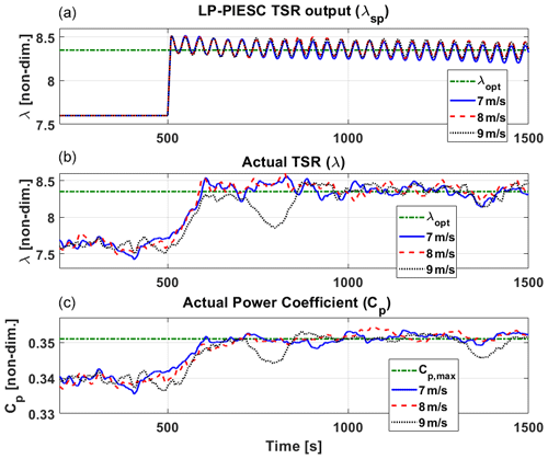
Figure 9Eroded-blade performance of the LP-PIESC algorithm with the parameters shown in Table A1 and hub-height wind from Fig. 5. The LP-PIESC algorithm is turned on at 500 s. Rate-limited LP-PIESC set-point tip-speed ratio λsp (a). Tip-speed ratio λ (b) and estimated power coefficient CP (c) from the OpenFAST output file. The horizontal dashed green lines indicate true optimal parameters λopt and CP,max (Fig. 3).
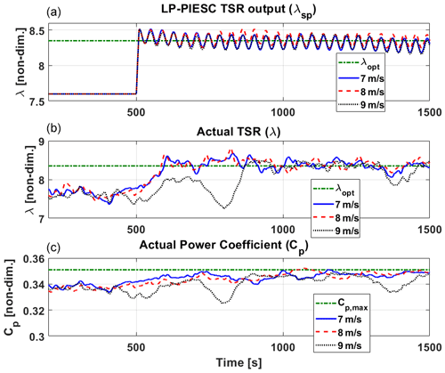
Figure 10Eroded-blade performance of the LP-PIESC algorithm with the parameters shown in Table A1 and wind input with 15 % TI. The LP-PIESC algorithm is turned on at 500 s. Rate-limited LP-PIESC set-point tip-speed ratio λsp (a), tip-speed ratio from the OpenFAST output λ (b), estimated power coefficient CP (c). The horizontal dashed green lines indicate true optimal parameters λopt and CP,max (Fig. 3).
The results in this section provided evidence, via simulations, that the LP-PIESC algorithm can quickly find the unknown optimal tip-speed ratio despite variations in the mean wind speed, turbulence intensity and level of blade degradation.
3.2.3 Energy capture
The energy capture using the LP-PIESC algorithm for both the contaminated-blade case and the eroded-blade case (Fig. 3) is evaluated and compared with the baseline controller (i.e., the controller with the tip-speed ratio constant and corresponding to clean blades). The controllers are evaluated for hub-height mean wind speeds of 7, 8 and 9 m s−1; vertical shear exponent α=0.2; and turbulence intensities of 10 % and 15 %, respectively. TurbSim (Jonkman, 2009) is used to generate the wind profiles from six different seeds for each wind speed and turbulence intensity. An average energy capture over those six wind profiles is presented here. All the calculations are done using the data from the time the LP-PIESC algorithm is turned on (500 s) until the end of the simulation (1500 s).
The contaminated-blade case is shown in Fig. 11. The average energy capture with the LP-PIESC algorithm is compared with that of the baseline controller. Both the controllers were applied to the same blades (contaminated for this case). The baseline controller applies a constant set-point tip-speed ratio λsp=7.6 to ROSCO, while the LP-PIESC algorithm applies the optimized tip-speed ratio time series λsp from Figs. 6 and 8. The energy capture with the LP-PIESC algorithm for the eroded blade was also compared with the baseline controller using the same approach. The average energy capture comparison for the eroded blade is shown in Fig. 12.
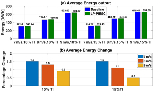
Figure 11Contaminated-blade energy capture comparison: baseline vs. LP-PIESC. Average energy output with the clean-blade optimal tip-speed ratio and the LP-PIESC (a), percentage change in energy capture (b).
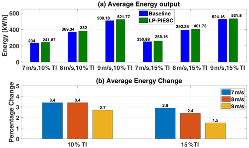
Figure 12Eroded-blade energy capture comparison: baseline vs. LP-PIESC. Average energy output with the clean-blade optimal tip-speed ratio and the LP-PIESC (a), percentage change in energy capture (b).
The results suggest that the LP-PIESC algorithm can find the unknown optimal tip-speed ratio for degraded rotor blades and improve the energy capture. The maximum improvement is observed with the mean wind speed of 7 m s−1 and 10 % TI wind for both the contaminated- (1.5 %) and the eroded-blade (3.4 %) cases. It is interesting to note that these improvements in energy capture are very close to the reported improvements in the power coefficient in Sect. 2.2 as explained in the caption of Fig. 3. The percentage of energy increase for the mean wind speed of 9 m s−1 was the lowest. In this case, turbulence takes the wind speed and generator speed in the above-rated region where the turbine blade-pitch controller gets activated to constrain the generated speed to the rated value.
The Log-Power Proportional-Integral Extremum Seeking Control (LP-PIESC) algorithm is presented to estimate the optimal tip-speed ratio (TSR) at below-rated wind speeds despite changes in the rotor aerodynamics. Knowledge of the optimal TSR is necessary when the wind turbine controller uses this information to determine to the generator speed set point for optimal power extraction.
The LP-PIESC algorithm's ability to identify optimal-TSR set points is demonstrated using OpenFAST simulations with the ROSCO reference controller introduced in Abbas et al. (2022). Optimal TSRs for blades with contaminated or eroded airfoils can be found despite variations in mean wind speed or turbulence intensity. The simulations show that re-tuning the TSR to optimal values can lead to increases in energy capture ranging from 0.5 % to 1.5 % for contaminated blades and from 1.5 % to 3.4 % for eroded blades. The highest energy increases occur at lower wind speeds, which is a favorable situation. Energy increases with eroded blades are higher than with contaminated blades for all cases considered. These positive results need to be balanced with the fact that, for both contaminated- and eroded-blade optimal-TSR increases, higher rotor speeds are required. The implications of this fact on the progression of blade degradation need to be better understood. However, the method proposed can be used to increase energy capture until blades need to be cleaned or repaired.
The LP-PIESC technique provides rapid and consistent convergence across different below-rated wind speed conditions. Calibration of algorithm parameters at one wind condition works at other wind conditions. However, the design of the PIESC algorithm requires tuning more parameters than the conventional ESC. Therefore, additional work is needed to establish practical guidelines for parameter design. The dither signal does create a harmonic component in the generator torque. While the impact of this dither-induced harmonic has not been studied, it should be noted that a stopping criterion could be added to eliminate the dither or the dither could be turned off after a fixed number of cycles. In fact, given the speed of convergence, even a partial cycle may suffice to estimate the optimal TSR. It is also important to note that if the turbine controller requires the CP–λ curve for wind speed estimation or another control function, then estimating the optimal set-point TSR under blade degradation may not suffice to realize power gains; additional parameters would need to be estimated in this case to optimize power for aerodynamically degraded rotors.
The method utilized to determine the unknown time-varying parameter contributes to the improvement in convergence time for this class of extremum-seeking control algorithms. This appendix describes the main features of the parameter estimation used. Let y(t) represent the log-of-power signal entering the LP-PIESC algorithm shown in Fig. 4. Using Guay and Dochain (2017), the rate of change in y is parameterized as
where u and are defined in Eq. (2), is the “regressor” in Eq. (A1) and is the two unknown time-varying parameters. Although θ0 is not used in the control equation (Eq. 2), this parameter is required to estimate θ1 properly (Guay and Dochain, 2017).
The parameter vector θ is estimated by minimizing an output prediction error e of the log-power signal y. The prediction error e is computed using
where is the prediction of the output y, obtained from the following ODE:
The positive scalar K is a parameter to be determined, and c(t) is a filtered regressor calculated from
It should be noted that the output prediction dynamics in Eq. (A3) comprises two additional terms, one proportional to the error e and the other proportional to the time derivative of the estimated time-varying parameter , in addition to a model of the dynamics . Intuitively, the addition of this latter term facilitates tracking time-varying parameters.
Finally, the updating law for parameter estimation is
where the Lipschitz projection operator Proj(⋅) is used to assure stability and that the estimates are bounded within the constraint set. This projection algorithm was implemented as described in Appendix E of Krstić et al. (1995), and the constraint set adaptation was adopted in accordance with Adetola and Guay (2011). The auxiliary variable estimate is given by
The 2×2 matrix Σ is the solution of the matrix differential equation
with σ and kT as positive scalar constants. The inverse of Σ is given by the solution of the ODE:
This is the ODE we integrate in the algorithm to obtain the gain matrix in the update law (Eq. A5). The matrix update law in Eq. (A7) is similar to the one in continuous-time least squares with forgetting (Shaferman et al., 2021).
A condition for the convergence of the PIESC algorithm (Guay and Dochain, 2017) is the level of excitation provided by the filtered regressor c(t) in Eq. (A4). This is quantified by the following persistence-of-excitation (PE) condition: there exists constants ρ>0 and T>0 such that
The dither signal provides a sufficient condition to satisfy Eq. (A9), which is the PE condition in assumption 5 of Guay and Dochain (2017). This assumption is used to prove the convergence of the PIESC algorithm to a neighborhood of the unknown optimum using a Lyapunov stability argument. While our dither is of low frequency, we have observed that the PE condition is satisfied after turning the dither on as shown by the following integral calculated over 1 s after turning on the algorithm:
At this time, we do not have a full explanation for the rapid satisfaction of the PE condition.
It must be noted that six parameters are needed to define the PIESC algorithm: kp, τI and kb for the PI control (Eq. 2) and K, kT and σ for the parameter estimation. In this paper we have used trial and error to determine these parameters. The selection of these parameters was done using a clean blade (no contamination or erosion), and then they were fixed at the design values for the degraded-blade cases, which would be a reasonable way of deploying the algorithm in the field. The parameters were designed assuming 8 m s−1 mean wind speed and 10 % TI. Parameter selection by trial and error requires initial conditions for the TSR other than the optimal value for clean blades λopt=7.6. These initial conditions taken were λ=9 (above optimal) and λ=6 (below optimal). Both the dither frequency and amplitude were determined following the procedure explained below.
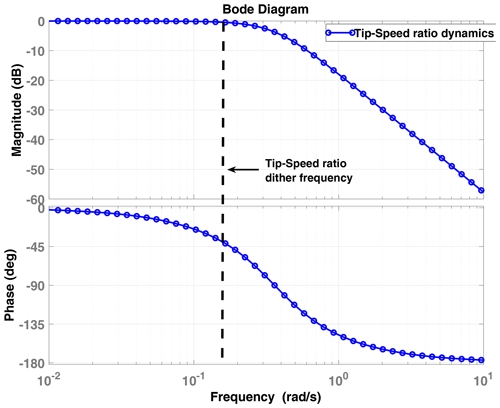
To complete the PIESC design, the frequency and amplitude of the sinusoidal dither signal d(t) in Eq. (2) must be specified. Again, assuming a clean blade operating at its optimal TSR, the dither frequency is chosen within the bandwidth of the plant dynamics as recommended in Ariyur and Krstic (2003) and Rotea (2000). The rotor inertia and the actuator dynamics yield the input dynamics. The input dynamics is merged with the plant and estimated using open-loop step responses under constant wind input to simplify the design. The response of the rotor speed (ωr) under staircase step changes in the tip-speed ratio indicates a second-order dynamics (a first-order wind turbine dynamics and the dynamics of the generator torque PI controller, approximately), as shown in Fig. A1. Figure A1a shows the staircase tip-speed ratio command to ROSCO and the OpenFAST tip-speed ratio output, while the rotor speed is shown in Figure A1b. The test was performed for the hub-height mean wind speed of 8 m s−1 with no turbulence. Based on the step response of the rotor speed, the natural frequency (ωn) and damping ratio (ζ) were calculated for each step change case. The undamped natural frequency ωn ranged between 0.36 to 0.5 rad s−1 while ζ ranged between 0.56 and 0.77. Then we calculated the time constant (i.e., ) for each case, and the slowest combination (i.e., largest time constant) was adopted for the LP-PIESC design, i.e., ωn=0.36 rad s−1 and ζ=0.76. The corresponding bandwidth is 0.33 rad s−1. Since dither frequency should be selected within the estimated bandwidth, it was selected conservatively as 0.16 rad s−1. The Bode plot for the estimated plant dynamic is shown in Fig. A2. The dither amplitude was selected using trial and error.
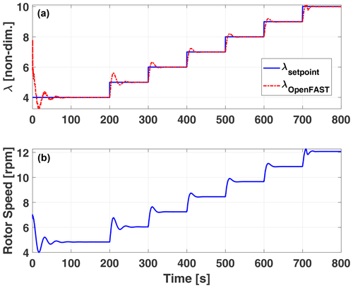
Figure A1The top plot shows the staircase tip-speed ratio command to ROSCO and the OpenFAST tip-speed ratio output, while the bottom plot shows the rotor speed response.
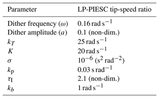
Finally, the parameters of the LP-PIESC scheme are listed in Table A1. The minimum and maximum saturation limits for the set-point tip-speed ratio were set at 4 and 10 (Eq. 2) to avoid very low or very high set-point TSR changes.
Table A1LP-PIESC parameters for set-point tip-speed ratio adjustment (see Fig.4).
We conclude this appendix with further details concerning tuning the six PIESC parameters needed to define the algorithm: kp, τI and kb for the PI control in Eq. (2) and K, kT and σ for the estimator in Eq. (A5). The trial-and-error process is a simulation-based method where we looked for consistent parameter convergence and converging to zero, which we know is the correct asymptotic value for this parameter. Once these three parameters were tuned, we tuned the PI parameters for better TSR convergence to its known value for a clean blade. After the desired response was obtained (on a clean blade), parameters were fixed and used for all other simulations with the LP-PIESC algorithm and different mean wind speeds and turbulence intensities.
The data presented in this work can be made available upon request.
DK: data curation, formal analysis, investigation, software, visualization, writing (original draft preparation). MAR: conceptualization, funding acquisition, methodology, resources, supervision, visualization, writing (review and editing).
The contact author has declared that neither of the authors has any competing interests.
Publisher's note: Copernicus Publications remains neutral with regard to jurisdictional claims made in the text, published maps, institutional affiliations, or any other geographical representation in this paper. While Copernicus Publications makes every effort to include appropriate place names, the final responsibility lies with the authors.
This work was supported in part by the Center for Wind Energy at the University of Texas at Dallas.
A preliminary version of this work was presented at the Wind Energy Science Conference 2023, Glasgow, UK, with partial support from the Center for Wind Energy, Strategic Center Investment, UT Dallas.
This paper was edited by Jan-Willem van Wingerden and reviewed by four anonymous referees.
Abbas, N. J., Zalkind, D. S., Pao, L., and Wright, A.: A reference open-source controller for fixed and floating offshore wind turbines, Wind Energ. Sci., 7, 53–73, https://doi.org/10.5194/wes-7-53-2022, 2022. a, b, c, d, e
Adetola, V. and Guay, M.: Robust adaptive MPC for constrained uncertain nonlinear systems, Int. J. Adapt. Contr. Sig. Process., 25, 155–167, 2011. a
Ariyur, K. B. and Krstic, M.: Real-time optimization by extremum-seeking control, John Wiley & Sons, print ISBN 9780471468592, online ISBN 9780471669784, https://doi.org/10.1002/0471669784, 2003. a
Burton, T., Jenkins, N., Sharpe, D., and Bossanyi, E.: Wind energy handbook, John Wiley & Sons, print ISBN 9780470699751, online ISBN 9781119992714, https://doi.org/10.1002/9781119992714, 2011. a, b
Ciri, U., Rotea, M., Santoni, C., and Leonardi, S.: Large-eddy simulations with extremum-seeking control for individual wind turbine power optimization, Wind Energy, 20, 1617–1634, https://doi.org/10.1002/we.2112, 2017. a
Ciri, U., Leonardi, S., and Rotea, M. A.: Evaluation of log-of-power extremum seeking control for wind turbines using large eddy simulations, Wind Energy, 22, 992–1002, 2019. a, b
Creaby, J., Li, Y., and Seem, J. E.: Maximizing Wind Turbine Energy Capture Using Multivariable Extremum Seeking Control, Wind Eng., 33, 361–387, 2009. a, b
De Kooning, J. D. M., Gevaert, L., Van de Vyver, J., Vandoorn, T. L., and Vandevelde, L.: Online estimation of the power coefficient versus tip-speed ratio curve of wind turbines, in: IECON 2013 – 39th Annual Conference of the IEEE Industrial Electronics Society, 10–13 November 2013, Vienna, Austria, 1792–1797, https://doi.org/10.1109/IECON.2013.6699403, 2013. a
Ehrmann, R. S., White, E. B., Maniaci, D. C., Chow, R., Langel, C. M., and Van Dam, C. P.: Realistic leading-edge roughness effects on airfoil performance, in: 31st AIAA Applied Aerodynamics Conference, 24–27 June 2013, San Diego, CA, p. 2800, https://doi.org/10.2514/6.2013-2800, 2013. a, b
Ehrmann, R. S., Wilcox, B., White, E. B., and Maniaci, D. C.: Effect of Surface Roughness on Wind Turbine Performance, Tech. rep., SNL-NM – Sandia National Lab., Albuquerque, NM, USA, https://energy.sandia.gov/wp-content/uploads/2017/10/LEE_Ehrmann_SAND2017-10669.pdf (last access: 27 October 2024), 2017. a, b
Guay, M. and Dochain, D.: A proportional-integral extremum-seeking controller design technique, Automatica, 77, 61–67, 2017. a, b, c, d, e, f, g
Han, W., Kim, J., and Kim, B.: Effects of contamination and erosion at the leading edge of blade tip airfoils on the annual energy production of wind turbines, Renew. Energy, 115, 817–823, https://doi.org/10.1016/j.renene.2017.09.002, 2018. a, b, c
IEC: Wind energy generation systems – part 1: design requirements, https://dlbargh.ir/mbayat/46.pdf (last access: 27 October 2024), 2005. a
IEC: Wind energy generation systems – Part 1: Design requirements, International Electrotechnical Commission, Geneva, Switzerland, https://webstore.iec.ch/en/publication/26423 (last access: 27 October 2024), 2019. a
Jonkman, B. J.: TurbSim user's guide: Version 1.50, Tech. rep., NREL – National Renewable Energy Lab., Golden, CO, USA, https://www.nrel.gov/docs/fy09osti/46198.pdf (last access: 27 October 2024), 2009. a, b
Jonkman, J.: The New Modularization Framework for the FAST Wind Turbine CAE Tool, in: 51st AIAA Aerospace Sciences Meeting including the New Horizons Forum and Aerospace Exposition, AIAA 2013-0202, 7–10 January 2013, Grapevine, Dallas/Ft. Worth Region, Texas, 1–26, https://doi.org/10.2514/6.2013-202, 2013. a
Jonkman, J., Butterfield, S., Musial, W., and Scott, G.: Definition of a 5-MW reference wind turbine for offshore system development, Tech. rep., NREL – National Renewable Energy Lab., Golden, CO, USA, https://www.nrel.gov/docs/fy09osti/38060.pdf (last access: 27 October 2024), 2009. a, b, c, d
Krstić, M. and Wang, H.-H.: Stability of extremum seeking feedback for general nonlinear dynamic systems, Automatica, 36, 595–601, 2000. a, b
Krstić, M., Kokotovic, P. V., and Kanellakopoulos, I.: Nonlinear and Adaptive Control Design, in: 1st Edn., John Wiley & Sons, Inc., USA, ISBN 0471127329, 1995. a, b
Kumar, D. and Rotea, M. A.: Wind Turbine Power Maximization Using Log-Power Proportional-Integral Extremum Seeking, Energies, 15, 1004, https://doi.org/10.3390/en15031004, 2022. a, b, c
Lio, W. H., Li, A., and Meng, F.: Real-time rotor effective wind speed estimation using Gaussian process regression and Kalman filtering, Renew. Energy, 169, 670–686, https://doi.org/10.1016/j.renene.2021.01.040, 2021. a
Manwell, J. F., McGowan, J. G., and Rogers, A. L.: Wind energy explained: theory, design and application, John Wiley & Sons, print ISBN 9780470015001, online ISBN 9781119994367, https://doi.org/10.1002/9781119994367, 2010. a
Meng, F., Lio, W. H., and Larsen, G. C.: Wind turbine LIDAR-assisted control: Power improvement, wind coherence and loads reduction, J. Phys.: Conf. Ser., 2265, 022060, https://doi.org/10.1088/1742-6596/2265/2/022060, 2022. a
NREL: OpenFAST, Version 2.3.0, GitHub [code], https://github.com/OpenFAST/openfast (last access: 12 February 2024), 2020. a, b, c
NREL: ROSCO, Version 2.4.0, GitHub [code], https://github.com/NREL/ROSCO/ (last access: 27 October 2024), 2021. a
Odgaard, P. F., Damgaard, C., and Nielsen, R.: On-Line Estimation of Wind Turbine Power Coefficients Using Unknown Input Observers, in: 17th IFAC World Congress, IFAC Proc. Vol., 41, 10646–10651, https://doi.org/10.3182/20080706-5-KR-1001.01804, 2008. a
Pao, L. Y. and Johnson, K. E.: Control of Wind Turbines, IEEE Control Syst., 31, 44–62, 2011. a
Petković, D., Žarko Ćojbašič, and Nikolić, V.: Adaptive neuro-fuzzy approach for wind turbine power coefficient estimation, Renew. Sustain. Energ. Rev., 28, 191–195, https://doi.org/10.1016/j.rser.2013.07.049, 2013. a
Rotea, M. A.: Analysis of multivariable extremum seeking algorithms, in: ACC (IEEE Cat. No. 00CH36334), vol. 1, Proceedings of the 2000 American Control Conference, 28–30 June 2000, Chicago, IL, USA, 433–437, https://doi.org/10.1109/ACC.2000.878937, 2000. a
Rotea, M. A.: Logarithmic Power Feedback for Extremum Seeking Control of Wind Turbines, IFAC-PapersOnLine, 50, in: 20th IFAC World Congress, 9–14 July 2017, Toulouse, France, 4504–4509, https://doi.org/10.1016/j.ifacol.2017.08.381 2017. a, b
Shaferman, V., Schwegel, M., Glück, T., and Kugi, A.: Continuous-time least-squares forgetting algorithms for indirect adaptive control, Eur. J. Control, 62, 105–112, 2021. a, b
Wilcox, B. and White, E.: Computational analysis of insect impingement patterns on wind turbine blades, Wind Energy, 19, 483–495, https://doi.org/10.1002/we.1846, 2016. a
Wilcox, B. J., White, E. B., and Maniaci, D. C.: Roughness sensitivity comparisons of wind turbine blade sections, Albuquerque, NM, https://energy.sandia.gov/wp-content/uploads/2017/10/LEE_Wilcox_SAND2017-11288.pdf (last access: 27 October 2024), 2017. a, b
Xiao, Y., Li, Y., and Rotea, M. A.: CART3 Field Tests for Wind Turbine Region-2 Operation With Extremum Seeking Controllers, IEEE T. Control Syst. Technol., 27, 1744–1752, 2019. a
Zanon, A., De Gennaro, M., and Kühnelt, H.: Wind energy harnessing of the NREL 5 MW reference wind turbine in icing conditions under different operational strategies, Renew. Energy, 115, 760–772, https://doi.org/10.1016/j.renene.2017.08.076, 2018. a
- Abstract
- Introduction
- Background
- Real-time identification of the optimal TSR with the LP-PIESC algorithm
- Conclusions
- Appendix A: Algorithm and design parameters for LP-PIESC estimation
- Data availability
- Author contributions
- Competing interests
- Disclaimer
- Acknowledgements
- Financial support
- Review statement
- References


