the Creative Commons Attribution 4.0 License.
the Creative Commons Attribution 4.0 License.
Comparison of different feedback controllers on an airfoil benchmark
Loïc Michel
Caroline Braud
Jean-Pierre Barbot
Franck Plestan
Dimitri Peaucelle
Xavier Boucher
The present paper proposes a comparison of three well-established controllers: a robust proportional–integral–derivative (PID) controller (Conord and Peaucelle, 2021), a model-free control (Fliess and Join, 2013, 2022) and an adaptive sliding-mode control based on the super-twisting algorithm (Shtessel et al., 2023). The benchmark considered is an airfoil section equipped with trailing edge jets, load sensors and a perturbation system. The objective is to track the lift command under external wind perturbations. The outcome of this work is the comparison of performances for three control laws that are suitable when little knowledge is known from the physics. This study quantifies performance not only in terms of load control, but also in the needed implementation effort.
- Article
(4493 KB) - Full-text XML
- BibTeX
- EndNote
The control of wind turbines is generally performed globally (rotor yaw or blade pitch control) to optimize the energy extraction or minimize the rotor's loads for a rotor's lifetime extension. This means that up to now no information from the blade aerodynamics has been taken into account in the control loop, but it is well understood that wind inflow interaction with blade aerodynamics can lead to power loss, load fluctuations and noise generation (see, e.g., Wagner et al., 2012; Rezaeiha et al., 2017). Wind turbines are exposed to inflow turbulence of different scales due to the atmosphere in which they operate (see, e.g., Schepers et al., 2021) as well as to rotor misalignment with the inflow or wakes of neighboring turbines. This is even more significant for offshore wind turbines whose rotor diameters are significantly larger, with local shear inflow over the rotor sweep area and even along the blades. To alleviate loads, the pitch control (Bossanyi, 2000) can be complemented by local and sometimes faster aerodynamic controllers. Local actuator types (e.g., vortex generators, flaps, slats, microjets/plasma) and sensor types (e.g., e-penons) have been developed for that purpose. Few contributions of control algorithms sufficiently robust to operate on the wind turbine blade aerodynamics have been proposed so far. Particularly, a significant number of controllers were investigated for NACA profiles with objectives towards aeronautic applications (see, e.g., Becker et al., 2007). More recently, different control technologies for wind energy applications were reviewed in Aubrun et al. (2017). Along with the development of active flow control (AFC) devices and open-loop tests came the development of closed-loop tests using advanced controllers, with the early work of Allan et al. (2000) using a model-based approach. A comprehensive review of control strategies dedicated to gust alleviation problems using active flow control is presented in Williams and King (2018). Feedback and feedforward structures based on system identification have been investigated for active load reduction in the context of a controlled wind turbine blade (see, e.g., Becker et al., 2005; Barlas et al., 2008; Li and Balas, 2013; Jaunet and Braud, 2018; Peaucelle et al., 2019; Bartholomay et al., 2021). At last, some model-free approaches were explored with a load alleviation objective in Becker et al. (2005), Michel et al. (2022) and Michel et al. (2024) based on different well-established modeling techniques from Scheinker (2024), Fliess and Join (2022), and Shtessel et al. (2023), respectively.
However, none of the control algorithms were compared on the same airfoil benchmark. It is well known that airfoils exhibit very different phenomena due to different shapes, Reynolds numbers etc. (see, e.g., McCullough and Gault, 1951; Gault, 1957) that are still being investigated (see, e.g., Brunner et al., 2021; Braud et al., 2024). In the present work different control strategies, model-based and model-free types, were investigated on the same airfoil configuration, which serves as a benchmark to highlight pros and cons with respect to different criteria.
The purpose of this study is to evaluate the performances of some selected feedback control strategies under different operating conditions of an experimental airfoil bench. The main goal is to alleviate aerodynamic load fluctuations, and this is tested with respect to large mean flow variations with turbulence superposed to it. The experimental setup is by itself a contribution as it can serve in the future to test more control laws in different configurations which are both simple and realistic compared to industrial applications. The second albeit main contribution is to design and test three types of controls: the robust PID controller (Conord and Peaucelle, 2021), a model-free control (Fliess and Join, 2013, 2022) and an adaptive sliding-mode control based on the super-twisting algorithm (Shtessel et al., 2023). The tests allow the characterization of operating domains for each control law regarding criteria like the nominal lift responses, the rejection of high-frequency fluctuations, and the robustness with respect to modifications on the dynamics due to changes in the air flow characteristics. The outcome of the study is a comprehensive exposure of the pros and cons of each feedback control approach, not only for the produced performances for the load control itself, but also in terms of needed efforts for the design and the implementation of these controls.
In this work, three control laws are being investigated. They have been chosen based on the experience of the automatic control collaborators of this study; rather than investigating all possible solutions at hand, we specifically selected those control strategies that are suitable for cases in which there is little precise knowledge on the system to control it and limited algorithmic complexity on the implementation level. The three control laws are as follows: (a) a robust proportional–integral–derivative (PID) controller (Conord and Peaucelle, 2021), which has the simplicity of the classic basic PID while providing potential robustness and being close to equilibrium perturbation rejection performances; (b) a model-free control (Fliess and Join, 2013, 2022), which requires little online tuning; and (c) an adaptive sliding-mode control based on the super-twisting algorithm (Shtessel et al., 2023), which also requires little knowledge about the model and has interesting finite-time convergence properties.
The paper is structured as follows. Section 2 presents the experimental setup. Section 3 presents the control problem and the control strategies that will be exploited. Section 4 discusses the results, and Sect. 5 gives some concluding remarks.
The main purpose of this experiment is to highlight the feasibility of using advanced control algorithms within a simplified flow configuration. Simplifications stand in the Reynolds number, the blade shape and the 2D section (no rotation and no transverse flow). This means that the flow characteristics (location of flow transition from laminar to turbulent, location of flow separation and thus aerodynamic loads) may differ from real applications. However, we show that even with such basic assumptions, the feedback control of the lift is possible and has sufficient robustness for potential usage in more realistic situations beyond 2D blade section assumptions.
In order to be self-content, we recall that the experimental closed-loop bench already presented in Michel et al. (2024) (see Fig. 1 for pictures and Fig. 2 for a functional scheme) is composed of a wind tunnel with its perturbation system (gust generator), a 2D aerodynamic blade profile equipped with microjets and load sensors to measure lift and drag.
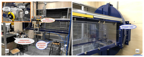
Figure 1The wind tunnel test bench is composed of the following: (a) the test section with all needed instrumentation (blade, load measurement system, angle sensor, acquisition and actuation systems) and (b) the perturbation system, also called the chopper (see Neunaber and Braud, 2020). The actuation system consists of a pressurized air circuit (blue tube) that is connected to a first reservoir on the bottom right of the image and to the solenoid valves set on the stool. Two vinyl tubes are connected from the exit of two solenoid valves to the ends of the hollow tube inside the blade. Reproduced from Michel et al. (2024).
2.1 Wind tunnel facility and gust generator
The LHEEA aerodynamic wind tunnel is a recirculating one. The test section has a cross-section of 500 mm×500 mm and a length of 2300 mm (Fig. 2). The turbulence intensity of an undisturbed inflow in the wind tunnel is around 0.3 %. In the present study, a grid is installed at the inlet of the test section to generate turbulent inflow with a turbulence intensity of 3 %. This bypasses the laminar-to-turbulent transition occurring at low Reynolds numbers and low angles of attack (AoAs) with respect to this blade geometry (see the linear part of the lift curve in Fig. 3).
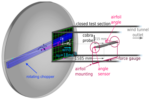
Figure 2Schematic of the wind tunnel test bench including the chopper and the uniform grid, the mounted airfoil, the angle sensor, and the force gauge (load sensor). Reproduced from Michel et al. (2024).
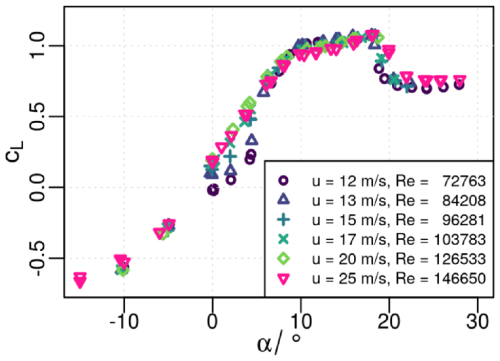
Figure 3Reynolds number effect on the lift coefficient curve: CL vs. the angle of attack α. Reproduced from Michel et al. (2024).
The inlet of the test section is additionally equipped with a system which enables the generation of a sudden variation of the mean flow with turbulence superimposed on it (for more details, see Neunaber and Braud, 2020). This system is called “chopper” and consists of a rotating bar that cuts through the inlet of the test section (Fig. 2).
2.2 Aerodynamic profile
A 2D blade section of type NACA 654-421 with a chord length of c=9.6 cm is installed in the test section of the wind tunnel.1 It is a thick profile with two changes in the lift curve corresponding to a first boundary layer separation at the trailing edge of the profile and a second flow separation at the leading edge, indicating stall (see Soulier et al., 2021, for more details on the blade aerodynamics). In the present study, the angle of incidence is set to α=20°, which corresponds to the maximum increase of the lift (see Fig. 3) considering the additional microjet.2 Further investigations are needed to extend the present work to other angles of incidence.
2.3 Microjets
To control the flow around the airfoil, holes of 1 mm diameter with equidistant 8 mm spacing are placed 1.92 cm from the airfoil's trailing edge, along the entire spanwise direction (Fig. 4). They are connected to a plenum chamber, itself fed with pressurized air at 6 bar. The plenum chamber is a hollow tube placed along and inside the blade, in the spanwise direction, tangent to the airfoil surface, with holes on it. Jets come out of these holes when hollow tube ends are connected to the air circuit. This prevents the individual control of jets; however, this ensures the jet amplitude homogeneity in the spanwise direction. The air circuit is connected to solenoid valves that switch on/off simultaneously, using a single control law so that synchronously pulsed microjets can be generated with a repetition rate of up to 300 Hz.
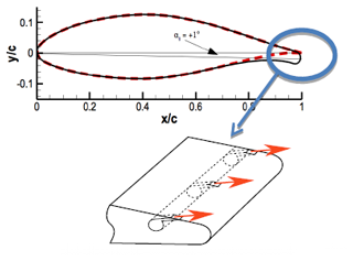
Figure 4Mechanical configuration of microjets on the blade section. Reproduced from Michel et al. (2024).
The action of the microjets is physically limited to the injection of pressurized air of a maximum of 6 bar, thus defining the range of the lift variations that can be compensated by the microjet actuator system. It is identified by a simple succession of valves opening and closing.
2.4 Lift and drag measurements
Two Z6FC3 HBM bending beam load cell sensors were used on each side of the blade support to measure the lift (Y1, Y2) and drag forces (X1, X2). They were calibrated in situ using calibrated weights from 0–5 kg in steps of 0.5 kg.
2.5 Control hardware
The control is managed by the STM32 Nucleo board H743ZI2, allowing a 16-bit ADC acquisition as well as the possibility of monitoring the signals in real time on the computer. The lift force is measured by the force balances (Y1,Y2) and is acquired at a sampling rate of 20 kHz using the Nucleo board. The signal is filtered using a fourth-order Butterworth filter with a cut-off frequency of 20 Hz. The control updates at 20 kHz and drives the valve at 200 Hz in response to the input from the force balances.
In this section, the control problem is presented with respect to the lack of aerodynamic modeling well adapted to the control design.
3.1 Problem statement
Throughout paper, the control of the lift is performed by a control loop that drives the pressurized air towards holes on the blade surface (Fig. 4), named microjets, which modifies the local pressure (which induces the lift), to track the lift reference. Since we use a small scale of the blade (), all the holes are driven by a single control law, assuming that the wind profile is equally distributed along the considered section of the blade under study.
In the sequel, the control input of the system is denoted u, and the output that is controlled, denoted y, is the lift force. Considering the lift reference y*, the goal of the closed-loop control is to ensure that the measured lift y converges accurately to y*.
The purpose of the study is to perform comparisons between controllers in order to evaluate performances such as time response, tracking precision and the delay of desaturation, taking into account the properties and the practical implementation of each controller, regarding several operating conditions of the lift control system.
3.1.1 PID robust control (PID)
The lift variation in response to microjet actuation can be modeled as a second-order system in first approximation (see Brunton and Rowley, 2011). Such an approximate model is highly dependent on the particular aerodynamic operating condition, including specific inflow velocity, and pitch. One way to cope with several operating points as a whole is to consider such second-order models with uncertain parameters. A rather simple way to build uncertain models can be achieved by considering a finite set of relevant operating points at which specific models are identified, assuming that the true parameters are in the convex set of the parameters obtained at these relevant operating points. Such modeling is known as polytopic modeling where state-space matrices can take infinitely many possible values within the set composed of all convex combinations of finitely many vertices. Robust control aims at assessing stability (and other performances) for all possible realizations of the system in the polytope. Robust evaluations of performances are necessarily pessimistic compared to the true performance of the system at one specific operating condition. On the other hand, it gives guarantees of the stability and other performances, at least as long as the modeling assumptions hold true.
In this paper, we used control design results from Conord and Peaucelle (2021) that are implemented in the R-RoMulOC toolbox Peaucelle et al. (2014). These results allow the design of state-feedback controllers. They rely on Lyapunov-type methods and solve the design problem based on linear matrix inequality formulas solved by semi-definite programming tools. We identified state-space representation in controllable canonical form where the states are the error between the reference y* and the true lift measure y and the time derivative of this error. An artificial state as the integral of the error is added; hence, the state-space design provides exactly a PID controller of the following type:
where Kp, Ki and Kd are designed gains.
In order to evaluate the influence of the identified models on the performances of the closed-loop system, we performed the design procedure for three different choices of polytopes. The design is systematic assuming the learning of appropriate second-order models is done and does not rely on tuning skills of some smart operator. The more operating points are considered, the more robust the controller shall be. Due to the above defined pessimism, it may also have poor performance at specific operating conditions. Poor performance can also come from discrepancies between true dynamics, which are non-linear, and the identified models.
3.1.2 Model-free control (MFC)
Full details on model-free control are given in Fliess and Join (2013). Its usefulness in many situations, including compensating severe non-linearities and time-varying reference signals, has been demonstrated (see, e.g., Lafont et al., 2020; Park et al., 2021). The corresponding intelligent controllers are much easier to implement and to tune than standard PID controllers, which are today the main tool in industrial control engineering (see, e.g., Åström and Murray, 2008).
The ultra-local model
In the current application, the unknown description of the plant is restricted to a SISO (single-input–single-output) system because the objective is to control only the lift y (output) using the actuator u (input). The unknown description of the SISO plant is replaced by an ultra-local first-order model (i.e., that approximates very locally the overall dynamics of the system; see Fliess and Join, 2013):
where the control and output variables are, respectively, u and y; the time-varying quantity F is estimated online and subsumes the unknown internal structure and the external disturbances. The constant β∈ℝ is chosen by the practitioner such that and βu are of the same magnitude. Therefore, β does not need to be precisely estimated.
Equation (2) is only valid during a short time lapse that must be continuously updated: it implies that F is estimated online through the knowledge of the control output u and the numerical differentiation of y. It is natural to consider firstly the ultra-local model (2) of the first order, for which, in the considered case, experimental results show that this particular order of the F model gives results that are accurate enough regarding the present objective of the paper (track lift reference).
Intelligent P controllers
The control law reads as the intelligent P controller (i-P controller):
where β is a parameter, and Kp is the usual tuning gain that has to be set by the user.
The i-P controller (3) compensates the poorly known term F. Controlling the system therefore boils down to the control of an elementary pure integrator. To numerically estimate the derivative of y, homogeneous semi-implicit differentiators have been used (see Michel et al., 2021; Mojallizadeh et al., 2023).
3.1.3 Adaptive super-twisting (AST) control
Full details on adaptive super-twisting can be found in Mirzaei et al. (2022). The dynamics of the tracking error are assumed to be given by
where a and b are unknown terms that are bounded in the operational domain; following the gained experience with MFC, it assumes that the relative degree is equal to one.3 The objective in this work is to leverage the properties of the adaptive super-twisting algorithm as a model-free control law, i.e.,, without any knowledge of a and b. From Plestan and Taleb (2021), the adaptive super-twisting controller is defined as
This includes the adaptive rules for the gains k1 and k2:
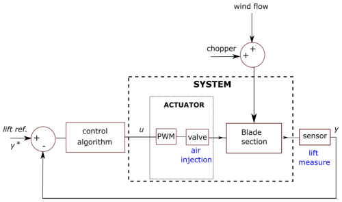
Figure 5Closed-loop schematic. The system is made of a plant, an actuator, and a perturbation that are, respectively, the blade section, the solenoid valves connected to compressed air and command through PWM signals, and variation of the mean flow or the chopper system.
where , and is the numerical estimation of . The main advantages of the AST controller are the following:
-
The adaptive algorithm requires only limited information about the system modeling.
-
The adaptive algorithm is well known for its robustness.
-
The adaptation of gains k1 and k2 helps reduce input energy consumption.
Note that these two approaches have different principles: the MFC can be considered an extended classical control, based on an internal estimation of an ultra-local model, that approximates online the dynamics of the controlled system, whereas the AST is a high-order sliding-mode controller whose gains are auto-adapted online and has conceptually a finite time convergence instead of an asymptotic convergence for all other tested control laws.
Figure 5 depicts the corresponding closed loop of the proposed control architecture, including the wind and chopper perturbations.
3.2 Control law improvement
To deal with the physical limits of the microjet actuator, which may create uncontrollable situations and unexpected behavior in the control algorithm in the presence of strong perturbations of the lift, an anti-windup procedure from Tarbouriech et al. (2011) is proposed to manage the integration part of the robust PID controller and the adaptive super-twisting algorithm when physical saturation occurs. In this study, only upper saturation is in effect due to the choice of particular experiment tests. Nevertheless, the actuator has upper and lower limitations due to the physical limitations of the experimental test bench.
3.2.1 Discretization of the control
To implement the control laws into the STM board, discretized versions have been derived from the continuous versions presented in the previous section. All control laws are “sampled” under basic Euler discretization strategies regarding the integrators' parts: PID contains a single integrator, and AST contains four integrators; these integrators were solved using for example a numerical trapezoidal rule. However, contrarily to the PID (1), the MFC ultra-local model structure (2) does not contain integrators. Consequently, the sole discretization problem refers to the numerical time derivative.
Due to the binary nature of the solenoid valves, the “continuous evolution” of the control output is converted into variations of the duty-cycle signal of a square signal that drives the valves; the period of the pulse-width modulation (PWM) is set to Tc=200 Hz. The quantification of the duty cycle is a very important issue that may affect the quality of the tracking, even the stability of the overall control. Although the control algorithms provide “continuous” values, the conversion into the duty-cycle format requires the quantification of the values of the control output since the practical implementation of the duty cycle is incremental: in particular, the pressure of 6 bar has been “swept” under a precision of 4000 points, meaning that the error of quantification of the pressure injected to the valve actuator is about bar. A high error of quantification gives less output resolution for the control to drive the pressure inducing strong oscillations of the measured lift. The choice of the precision is a compromise between “minimal” tracking performances of the lift and the capabilities of the STM board (related to the maximum clock frequency) to increase the incremental precision of the duty cycle since the control algorithm is updated at 20 kHz.
3.2.2 Definition of the saturation
The control is designed with respect to the saturation/physical limitation of the microjet actuator including a hysteresis and an anti-windup algorithm that interact with the numerical integration schemes of the controller.
Due to the physical limitation of the actuator, the output of the control is blocked/bounded when the control attempts to drive the lift outside the physical range of the admissible pressure of the valve actuator. The purpose of the anti-windup (AW) algorithm is complementary to the control blocking and holds the value of the control by freezing the integration part of the control algorithms to prevent divergence or an unexpected issue with the control. The anti-windup is tested in this work by considering the start of the lift reference greater than the physical allowed pressure.
-
In the PID case, the simplest solution is to freeze the integrator part during the saturation time.
-
In the AST case, the simplest solution is also to freeze all the integrators during the saturation time, especially the integration of the adaptive gains k1 and k2 since such adaptation is totally wrong while saturating.
-
In the MFC case, blocking on the control law, the output of the control using a simple saturation is a solution to maintain the “learning effect” of the control and satisfy the input constraints.
4.1 Practical implementation
The model-free-based approaches (MFC and AST) require little information, like the relative degree and the sign of gain of the system. Regarding the robust PID control, it requires transfer function modeling at some specific operating points.
-
A robust PID controller is typically the simplest controller to implement within an embedded calculator, and it can give excellent results for “unknown” dynamics, based on very rough modeling, but it is also very sensitive to changes and error in the modeling, which make the solution not efficient for such application, as the unsteady aerodynamics on wind turbine blades may vary significantly with atmospheric conditions. The recent advances in robust control design allow building a robust control based on rough polytopic modeling. This polytopic modeling induces also some implicit assumptions with respect to the model validity domain with regards to our application. Three polytopic models have been considered from different operating conditions (inflow velocity variations and different blockage ratios), in order to synthesize three PID controllers, whose robustness has been tested separately against the different proposed modeling. This approach requires an identification procedure to build the polytopes, and the resulting synthesis of the robust control has been done using a dedicated MATLAB® toolbox. The more precise the polytopic approximation, the more effective the control is, but this will require a lot of time and effort.
-
The MFC is of the same complexity as the PID, including a prediction part that requires the estimation of a numerical time derivative of y.
-
The AST contains several integrators that manage the dynamics of the internal integrator and the dynamics of the gains.
Both model-free solutions are of interest because they do not need any prior modeling of the system, making these solutions pretty well adapted to control fluid dynamics applications. The tuning of the MFC and AST has been done according to the experience gained by Michel et al. (2022, 2024) and is consequently faster than the PID robust design, which requires a complete identification procedure (see, e.g., Albertos and Sala, 2002).
4.2 Scenarios of operation
Several cases of operating conditions have been considered to compare the model-based approach (robust PID control) and the model-free-based approach (MFC and AST) in terms of usual performances: the sum of square error (SSE) representing the energy of the control signal (), the variation of the control input (), the usual standard deviation of the output y (), and the time responses and the desaturation time.
The efficiency of the lift tracking is evaluated for several scenarios that illustrate different operating conditions, defined by different inflow velocities and different fixed positions of the chopper in the test section, for which the characteristics are described below and are summarized in Table 1. The chopper induces different perturbation levels, defined as the ratio in percentage , with Sbar the chopper surface area introduced in the test section and S the surface area of the test section such as . Due to the difference in dynamics between the chopper displacement and aerodynamic phenomena including the microjet feedback loop, in this paper, the chopper is maintained at a fixed position for which its displacement is considered instantaneous.
The experiments are conducted considering a constant inflow velocity of 20 m s−1, except for scenario 1. The latter considers an inflow velocity of 19 m s−1, measured with a Pitot tube in front of the airfoil in the undisturbed flow (before the chopper) and an angle of attack of 20°. The tracking lift reference starts with a half sine that aims to provide some dynamics to initiate the control, and then, the reference is composed of several constant piecewise parts to induce small variations of the controlled lift. The chopper, when introduced slightly in the test section, reduces the mean inflow velocity and adds turbulence. The chopper is used to evaluate the robustness of the controllers under perturbations of the lift and is quantified using the ratio between the chopper surface area and the test section area as introduced in Sect. 2.1. Reported in percentage, it represents the blockage coefficient created by the chopper; the time duration during which the chopper is introduced in the test section is indicated together with the blockage coefficient in Table 1.
-
Scenario 1. This starting scenario considers the simplest case where the inflow velocity is set to a constant low value of 19 m s−1, and no perturbation is introduced.
-
Scenario 2. The inflow velocity is set to 20 m s−1, and the chopper is manually introduced at t<10 s to disturb the air flow (fixed at 0.6 %).
-
Scenario 3. The inflow velocity is set to 20 m s−1, and the chopper is manually introduced at t<10 s to disturb the air flow (fixed at 2.5 %).
-
Scenario 4. The inflow velocity is set to 20 m s−1, and then it is changed to 21 m s−1 at t=10 s. The chopper is manually introduced at the beginning to disturb the air flow (fixed at 0.6 %).
-
Scenario 5. The inflow velocity is set to 20 m s−1, and then it is changed to 21 m s−1 at t=10 s. The chopper is manually introduced at the beginning to disturb the air flow (fixed at 2.5 %).
-
Scenario 6. The inflow velocity is set to 20 m s−1. The chopper is introduced between t=10 s and t=60 s to disturb the air flow (fixed at 2.5 %).
To illustrate the operation of the saturation mode, a higher output reference than the maximum reachable lift is considered first in order to saturate the microjet actuator. Then a piecewise constant reference is applied to track the lift.
4.3 Setup of the controllers
Table 2 summarizes parameters of controllers that have been used for each scenario. In particular, concerning the PID control, the A, B and C controllers have been synthesized based on three polytopes that combine several operating conditions, which are summarized in Table 3.
If one adds the model identified for 2.5 % for the inflow velocity of 21.3 m s−1 to polytope A, the R-RoMulOC toolbox fails to find a solution. This could be either because of the conservativeness of the coded method or because no such robust PID exists.
4.4 Results and discussion
In this section, the experimental results are presented considering firstly no actuator saturation during the lift tracking and, then, with actuator saturation.
4.4.1 Analysis of performances in the case no control saturation
Throughout this subsection, it has been verified that the measured lift does not saturate, meaning that the evolution of the input u is not limited by the AW algorithm.
The performances of the controllers with respect to the tracking error are evaluated using the usual performances index: SSE, SD and VarU criteria, which inform about the control effort of each controller. Each index is averaged over the scenarios of operation, and the global comparison is presented in a histogram in Fig. 6. This histogram is found representative of all scenarios of Table 1, even when different blockage ratios were set (scenarios 2 and 3). Scenario 2 has been arbitrarily selected in the rest of the analysis to illustrate the averaged performance of Fig. 6. Figures 7–11 illustrate the tracking of the instantaneous lift for each MFC, AST, PID(A), PID(B) and PID(C) controller, according to the evolution of the corresponding duty cycle.
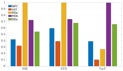
Figure 6Normalized performances of SSE, SD and VarU of the control laws (PID, MFC and AST) averaged over scenarios for each controller.
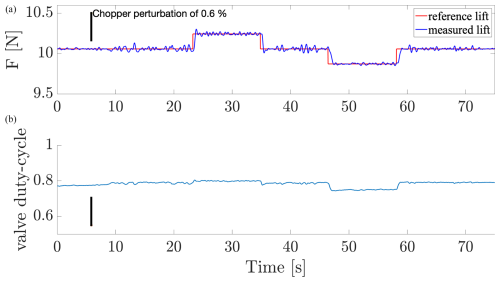
Figure 7Time evolution of the lift controlled by the MFC with respect to the lift reference (top) and associated duty cycle (bottom). The chopper introduction is marked by the vertical black line.
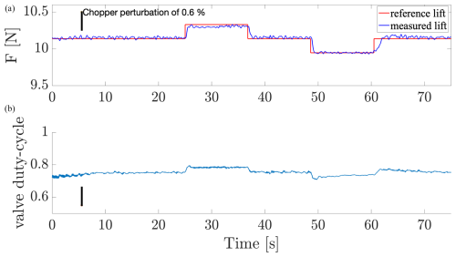
Figure 8Time evolution of the lift controlled by the AST with respect to the lift reference (top) and associated duty cycle (bottom). The chopper introduction is marked by the vertical black line.
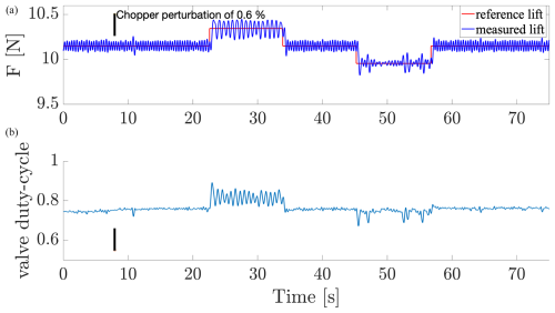
Figure 9Time evolution of the lift controlled by the PID(A) with respect to the lift reference (top) and associated duty cycle (bottom). The chopper introduction is marked by the vertical black line.
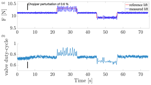
Figure 10Time evolution of the lift controlled by the PID(B) with respect to the lift reference (top) and associated duty cycle (bottom). The chopper introduction is marked by the vertical black line.
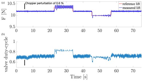
Figure 11Time evolution of the lift controlled by the PID(C) with respect to the lift reference (top) and associated duty cycle (bottom). The chopper introduction is marked by the vertical black line.
The model-free-based approaches require very little information about the dynamical system to control. In particular, the lack of information about the system uses learning properties or adaptive properties of such controller that has to “guess” the behavior of the system. The AST offers globally better performances over all scenarios than MFC controller due to the adaptive integrator and adaptive gains associated with a sliding-mode controller, which smooth the response according to high-frequency variations of the lift dynamics. The performances are however very similar in scenario 2 (depicted in Figs. 7 and 8). On the other hand, the MFC contains an anticipating action (via numerical derivation) instead of the adaptive action, which makes this controller more reactive to small aerodynamic perturbations.
The comparison of the tracking between the three PID controllers shows that the particular controller, associated with polytope C, shows a good tracking of the lift in the case of the perturbed wind flow including an inflow velocity change, meaning that this particular polytopic model matches the overall dynamics best, whereas the other polytope-based controllers give worse performances. Despite the strong difficulty to model the dynamics of the lift, one can assume that a very particular choice of the operating conditions to build the polytopic model could give interesting results. Note that the identification process of tuning the robust PID control makes it difficult to maintain rigorous operating conditions in the wind tunnel, considering the additional turbulence generated by the presence of the chopper. The identification has been performed by averaging several step responses of the measured lift. It is assumed that the dynamics of the microjet action are very fast compared to the dynamics of the wind flow, to consider such an averaged approximation. We still notice a posteriori that the identification assumption that the models depend on operating conditions and not on the average duty cycle (the effective actuation force) seems erroneous: this reflects very different dynamics depending on the value of the reference lift, for which a closer identification would improve the models.
Focusing on the static response of each controller around 15 s, Figs. 12 and 13 highlight the behavior of each controller for scenarios 2 and 5, respectively. In both cases, MFC and AST show smoother responses than PID controllers. The responses of the PID controllers remain harmonic, inducing a worse rejection of the aerodynamic perturbation. Globally, the nonlinear properties of AST and MFC allow a better reduction of the aerodynamic perturbations, whereas PID control is limited to rejecting disturbances and tends to amplify oscillations (Fig. 12). Nevertheless, if the perturbation induced by the chopper and variations of the mean inflow velocity increases, the rejection becomes less efficient for the nonlinear control AST and MFC (Fig. 13) but remains better than PID. Moreover, as observed previously in scenario 2, Figs. 9–11 highlight differences in the tracking efficiency according the level of the lift reference, hence showing the limitation of the considered robust PID control.
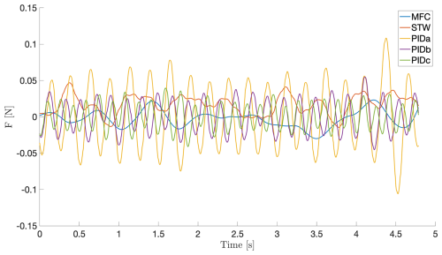
Figure 12Starting sequence of scenario 2 (see Table 1): comparison of the time evolution of the lift with each controller (PID, AST and MFC) for a constant inflow of 20 m s−1 and no perturbation from the chopper system.
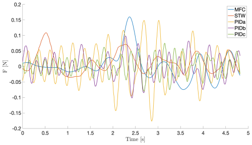
Figure 13Starting sequence of scenario 5 (see Table 1): comparison of the time evolution of the lift with each controller (PID, AST and MFC) for a constant inflow of 20 m s−1 and no perturbation from the chopper system.
In Fig. 8, the time needed for the AST controller to converge to the reference is slower due to the adaptation of the gains; this convergence issue is not general and depends strongly on the operation conditions. Due to the internal anticipation of the MFC structure, Fig. 7 shows good convergence to the reference, which is very similar to the behavior of the PID controllers.
Regarding the MFC and AST, these strategies are based on very minimal knowledge of the system dynamics under study: like the sign of the global transfer and the relative degree (the number of times that the input of the system is derived in order to obtain the output), the sampling period is also of importance since it imposes limitations in the range of the gains. From the gained experience, a rough tuning of the parameters already provides correct performances. Better performances could be obtained by using an online optimization procedure that aims for example to minimize the sum of square error of the controlled lift over several sections of time. Nevertheless, this approach has not been envisaged in this paper because of limited available time in the wind tunnel. It requires further developments to include an optimization algorithm in the embedded control, and measurements take time.
4.4.2 Analysis of performances in case of control saturation
The problem of saturation comes from the presence of an integrator inside the controllers, hence introducing an anti-windup algorithm to prevent the integrators from diverging (which induces in this case a saturation of the output y). As the MFC controller does not contain a numerical integrator, the problem of the desaturation using an AW algorithm concerns only the AST and PID controllers.
In the case of scenario 2, Figs. 14–17 illustrate the tracking of the instantaneous lift for, respectively, the AST, PID(A), PID(B) and PID(C) controllers during the saturation mode, involving the anti-windup (AW) algorithm, at the beginning of the control operation.
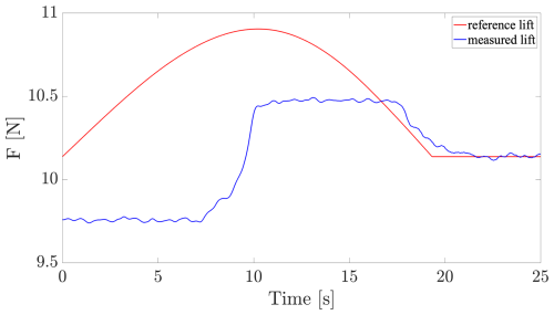
Figure 14Saturation test: time evolution of the lift controlled by the AST algorithm under saturation (in blue) with respect to the lift reference (in red).
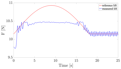
Figure 15Saturation test: time evolution of the lift controlled by the PID(A) algorithm under saturation (in blue) with respect to the lift reference (in red).
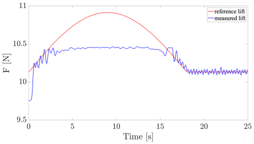
Figure 16Saturation test: time evolution of the lift controlled by the PID(B) algorithm under saturation (in blue) with respect to the lift reference (in red).
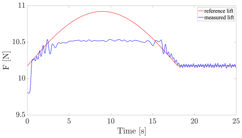
Figure 17Saturation test: time evolution of the lift controlled by the PID(C) algorithm under saturation (in blue) with respect to the lift reference (in red).
The easiest AW algorithm is typically applied for the PID control (see, e.g., Franklin et al., 1994, chap. 9 of the sixth edition) for which a single integrator needs to be frozen when saturation occurs. Conversely, the more complex one is the AST, for which it is required to freeze four integrators (v, μ, k1 and k2) using a particular sequencing with respect to the gains management, which makes the tuning of its AW more difficult. The desaturation depends mainly on the integrators and gains; hence, the AST desaturation is slower. This is due to the time needed to re-adapt the gains (in the considered PID, the gains are fixed). In Fig. 14, the behavior until 10 s corresponds to the initialization sequence of k1 and k2 integrators. In order to highlight the initial adaptive time, both gains are initialized at very small values.
This work provides comprehensive knowledge from the gained experience about the practical design and implementation of some feedback control laws that succeed in performing aerodynamic lift control with active flow actuators. The investigations lead us to conceive an appropriate test bench focusing on the lift control problem. Three control strategies have been selected, the parameters of the controllers have been designed and implementation has been carried out on the test bench. In summary, the conclusions of each control are the following. The model-based strategy for the design of robust PID control has the advantage of being rather systematic but is highly dependent on prior model identification. As it assumes linear representation of the plant, it is expected to perform mainly when the system is close to the set point. The two other control strategies are model-free (or assuming basic properties on the plant) but require hand-tuning, which may not be systematic. It revealed to be rather simple in the MFC case and did not need a posteriori to build some anti-windup strategy to cope with saturation issues. The features of the adaptive super-twisting control revealed rather smooth time responses. Comparing all tuned controllers in terms of closed-loop performances as well as the design and development time, MFC appears to be a good compromise in case of saturation, while AST provides slightly smoother responses. We are conscious that the conclusions in terms of performances may differ when applying other values on the control parameters. We do not claim that the values are unique or optimal. It may well be that the hierarchy of results changes for other versions of these same controls. One of the perspectives of the automatic-control colleagues involved in the project is to establish mathematical tools to tune control parameters such that the controllers, at least locally, provide similar results. But this is beyond the scope of the present work.
All data (dataset and MATLAB scripts to plot all figures) are available on Zenodo: https://doi.org/10.5281/zenodo.10617751 (Michel, 2024).
LM carried out the conceptualization, the methodology, investigations, the software design and the preparation of the full paper. CB, JPB and FP carried out the conceptualization, the methodology, investigations and the preparation of the full paper. In addition, CB provided the experimental resources, and CB and FP carried out the funding acquisition. DP provided knowledge about robust PID design tools as well as a ready-to-use code for designing the control gains for given polytopes and participated to the review of the paper. XB participated in the software design and the writing of the paper.
The contact author has declared that none of the authors has any competing interests.
Publisher's note: Copernicus Publications remains neutral with regard to jurisdictional claims made in the text, published maps, institutional affiliations, or any other geographical representation in this paper. While Copernicus Publications makes every effort to include appropriate place names, the final responsibility lies with the authors.
The authors thank Michel Fliess and Cédric Join for their fruitful advice with respect to the model-free control algorithm implementation, which was the starting point of our previous investigations of this study. The authors thank Pierre Molinaro for the design of the electronic control board in the experimental setup.
This research has been supported by the Agence Nationale de la Recherche (grant no. CREATIF ANR-20-CE05-0039), the WEst Atlantic Marine Energy Community (ASAPe and FOWTBLADE), and the Association des Instituts Carnot (CARNOT MERS – project GOWIBA). Jean-Pierre Barbot is supported by Région Pays-de-la-Loire within the Connect Talent GENYDROGENE project.
This paper was edited by Jens Nørkær Sørensen and reviewed by three anonymous referees.
Albertos, P. and Sala, A.: Iterative identification and control: advances in theory and applications, Springer, ISBN 978-1-4471-1098-9, https://doi.org/10.1007/978-1-4471-0205-2, 2002. a
Allan, B. G., Juang, J., Raney, D. L., Seifert, A., Pack, L. G., and Brown, D. E.: Closed-loop separation control using oscillatory flow excitation, Tech. rep., NASA/CR-2000-210324, ICASE Report 2000-32, NASA, https://ntrs.nasa.gov/api/citations/20000108735/downloads/20000108735.pdf (last access: 16 January 2025), 2000. a
Åström, K. J. and Murray, R. M.: Feedback systems, Princeton University Press, ISBN 13:978-0-691-13576-2, 2008. a
Aubrun, S., Leroy, A., and Devinant, P.: A review of wind turbine-oriented active flow control strategies, Exp. Fluids, 58, 134, https://doi.org/10.1007/s00348-017-2412-0, 2017. a
Barlas, T., van Wingerden, J. W., Hulskamp, A., and van Kuik, G.: Closed-Loop control wind tunnel tests on an adaptive wind turbine blade for load reduction, in: 46th AIAA Aerospace Sciences Meeting and Exhibit, 7–10 January 2008, Reno, Nevada, https://doi.org/10.2514/6.2008-1318, 2008. a
Bartholomay, S., Wester, T. T. B., Perez-Becker, S., Konze, S., Menzel, C., Hölling, M., Spickenheuer, A., Peinke, J., Nayeri, C. N., Paschereit, C. O., and Oberleithner, K.: Pressure-based lift estimation and its application to feedforward load control employing trailing-edge flaps, Wind Energy Science, 6, 221–245, https://doi.org/10.5194/wes-6-221-2021, 2021. a
Becker, R., Garwon, M., Gutknecht, C., Barwolf, G., and King, R.: Robust control of separated shear flows in simulation and experiment, J. Process Control, 15, 691–700, 2005. a, b
Becker, R., King, R., Petz, R., and Nitsche, W.: Adative Closed-loop separation control on a high-lift configuration using extremum seeking, AIAA J., 45, 1382–1392, 2007. a
Bossanyi, E.: The design of closed loop controllers for wind turbines, Wind Energy, 3, 149–163, 2000. a
Braud, C., Podvin, B., and Deparday, J.: Study of the wall pressure variations on the stall inception of a thick cambered profile at high Reynolds number, Phys. Rev. Fluids, 9, 014605, https://doi.org/10.1103/PhysRevFluids.9.014605, 2024. a
Brunner, C. E., Kiefer, J., Hansen, M. O. L., and Hultmark, M.: Study of Reynolds number effects on the aerodynamics of a moderately thick airfoil using a high-pressure wind tunnel, Exp. Fluids, 62, 178, https://doi.org/10.1007/s00348-021-03267-8, 2021. a
Brunton, S. and Rowley, C.: Low-dimensional state-space representations for classical unsteady aerodynamic models, in: 49th AIAA Aerospace Sciences Meeting including the New Horizons Forum and Aerospace Exposition, 4–7 January 2011, Orlando, Florida, https://doi.org/10.2514/6.2011-476, 2011. a
Conord, T. and Peaucelle, D.: Multi-Performance State-Feedback for Time-Varying Linear Systems, in: Third IFAC Conference on Modelling, Identification and Control of Nonlinear Systems – MICNON 2021, September 2021, Online, Japan, https://hal.laas.fr/hal-03176042 (last access: 10 January 2025), 2021. a, b, c, d
Fliess, M. and Join, C.: Model-free control, Int. J. Control, 86, 2228–2252, 2013. a, b, c, d, e
Fliess, M. and Join, C.: An alternative to proportional-integral and proportional-integral-derivative regulators: Intelligent proportional-derivative regulators, Int. J. Robust Nonlin. Control, 32, 9512–9524, 2022. a, b, c, d
Franklin, G., Powell, J., and Emami-Naeini, A.: Feedback control of dynamic systems, Addison-Wesley, ISBN 10:0201527472, ISBN 13:978-0201527476, 1994. a
Gault, D. E.: A correlation of low-speed airfoil-section stalling characteristics with Reynolds number and airfoil geometry, Tech. Rep. Technical note 3963, National Advisory Committee for Aeronautics, https://ntrs.nasa.gov/citations/19930084707 (last access: 17 January 2025), 1957. a
Isidori, A.: Nonlinear control systems: an introduction, Springer, ISBN 3662025817, ISBN 9783662025819, 1985. a
Jaunet, V. and Braud, C.: Experiments on lift dynamics and feedback control of a wind turbine blade section, Renew. Energ., 126, 65–78, 2018. a
Lafont, F., Balmat, J.-F., Join, C., and Fliesś, M.: First steps toward a simple but efficient model-free control synthesis for variable-speed wind turbines, International Journal of Circuits, Systems and Signal Processing, 14, 1181–1191, 2020. a
Li, N. and Balas, M. J.: Adaptive Flow Control of Wind Turbine Blade Using Microtabs with Unsteady Aerodynamic Loads, in: 2013 IEEE Green Technologies Conference (GreenTech), 4–5 April 2013, Denver, CO, USA, 134–139, https://doi.org/10.1109/greentech.2013.28, 2013. a
McCullough, G. B. and Gault, D. E.: Example of three representative types of airfoil-section stall at low speed, Technical Note NACA TN 2502, National Advisory Committee for Aeronautics, Moffett Field, California, USA, https://ntrs.nasa.gov/citations/19930083422 (last access: 17 January 2025), 1951. a
Michel, L.: Feedback flow controllers to reattach the flow over airfoils, Zenodo [code and data set], https://doi.org/10.5281/zenodo.10617751, 2024. a
Michel, L., Selvarajan, S., Ghanes, M., Plestan, F., Aoustin, Y., and Barbot, J.-P.: An experimental investigation of discretized homogeneous differentiators: pneumatic actuator case, IEEE Journal of Emerging and Selected Topics in Industrial Electronics, 2, 227–236, https://doi.org/10.1109/JESTIE.2021.3061924, 2021. a
Michel, L., Neunaber, I., Mishra, R., Braud, C., Plestan, F., Barbot, J.-P., Boucher, X., Join, C., and Fliess, M.: Model-free control of the dynamic lift of a wind turbine blade section: experimental results, J. Phys. Conf. Ser., 2265, 032068, https://doi.org/10.1088/1742-6596/2265/3/032068, 2022. a, b
Michel, L., Neunaber, I., Mishra, R., Braud, C., Plestan, F., Barbot, J.-P., and Hamon, P.: A novel lift controller for a wind turbine blade section using an active flow control device including saturations: experimental eesults, IEEE T. Contr. Syst. T., 32, 1590–1601, https://doi.org/10.1109/TCST.2023.3345208, 2024. a, b, c, d, e, f, g, h
Mirzaei, M. J., Hamida, M. A., Plestan, F., and Taleb, M.: Super-twisting sliding mode controller with self-tuning adaptive gains, Eur. J. Control, 68, 100690, https://doi.org/10.1016/j.ejcon.2022.100690, 2022. a
Mojallizadeh, M. R., Brogliato, B., Polyakov, A., Selvarajan, S., Michel, L., Plestan, F., Ghanes, M., Barbot, J.-P., and Aoustin, Y.: A survey on the discrete-time differentiators in closed-loop control systems: experiments on an electro-pneumatic system, Control Eng. Pract., 136, 105546, https://doi.org/10.1016/j.conengprac.2023.105546, 2023. a
Neunaber, I. and Braud, C.: First characterization of a new perturbation system for gust generation: the chopper, Wind Energ. Sci., 5, 759–773, https://doi.org/10.5194/wes-5-759-2020, 2020. a, b
Park, B., Zhang, Y., Olama, M., and Kuruganti, T.: Model-free control for frequency response support in microgrids utilizing wind turbines, Electr. Pow. Syst. Res., 194, 107080, https://doi.org/10.1016/j.epsr.2021.107080, 2021. a
Peaucelle, D., Tremba, A., Arzelier, D., Bortott, A., Calafiore, G., Chevarria, G., Dabbene, F., Polyak, B., Shcherbakov, P., Sevin, M., Spiesser, P., and Tempo, R.: R-RoMulOC: randomized and robust multi-objective control toolbox, https://projects.laas.fr/OLOCEP/rromuloc/ (last access: 17 January 2025), 2014. a
Peaucelle, D., Guilmineau, E., and Braud, C.: Towards robust control design for active flow control on wind turbine blades, in: Wind Energy Science Conference 2019, 706, 17–20 June 2019, Cork, Ireland, https://hal.science/hal-02888544 (last access: 17 January 2025), 2019. a
Plestan, F. and Taleb, M.: Adaptive supertwisting controller with reduced set of parameters, in: 2021 European Control Conference (ECC), 29-June–2 July 2021, Delft, the Netherlands, 2627–2632, https://doi.org/10.23919/ECC54610.2021.9655180, 2021. a
Rezaeiha, A., Pereira, R., and Kotsonis, M.: Fluctuations of angle of attack and lift coefficient and the resultant fatigue loads for a large horizontal axis wind turbine, Renew. Energ., 114, 904–916, https://doi.org/10.1016/j.renene.2017.07.101, 2017. a
Scheinker, A.: 100 years of extremum seeking: A survey, Automatica, 161, 111481, https://doi.org/10.1016/j.automatica.2023.111481, 2024. a
Schepers, J., Boorsma, K., Madsen, H., Pirrung, G., Bangga, G., Guma, G., Lutz, T., Potentier, T., Braud, C., Guilmineau, E., Croce, A., Cacciola, S., Schaffarczyk, A. P., Lobo, B. A., Ivanell, S., Asmuth, H., Bertagnolio, F., Sørensen, N., Shen, W. Z., Grinderslev, C., Forsting, A. M., Blondel, F., Bozonnet, P., Boisard, R., Yassin, K., Hoening, L., Stoevesandt, B., Imiela, M., Greco, L., Testa, C., Magionesi, F., Vijayakumar, G., Ananthan, S., Sprague, M. A., Branlard, E., Jonkman, J., Carrion, M., Parkinson, S., and Cicirello, E.: IEA Wind TCP Task 29, Phase IV: Detailed Aerodynamics of Wind Turbines, Zenodo [data set], https://doi.org/10.5281/zenodo.4813068, 2021. a
Shtessel, Y., Plestan, F., Edwards, C., and Levant, A.: Adaptive sliding mode and higher order sliding-mode control techniques with applications: a survey, pp. 267–305, Springer International Publishing, Cham, https://doi.org/10.1007/978-3-031-37089-2_11, 2023. a, b, c, d
Soulier, A., Braud, C., Voisin, D., and Podvin, B.: Low-Reynolds-number investigations on the ability of the strip of e-TellTale sensor to detect the flow features over wind turbine blade section: flow stall and reattachment dynamics, Wind Energ. Sci., 6, 409–426, https://doi.org/10.5194/wes-6-409-2021, 2021. a
Tarbouriech, S., Garcia, G., Silva, J., and Queinnec, I.: Stability and stabilization of linear systems with saturating actuators, Springer, ISBN 978-0-85729-940-6, https://doi.org/10.1007/978-0-85729-941-3, 2011. a
Wagner, S., Bareiß, R., and Guidati, G.: Wind turbine noise, Springer Science & Business Media, ISBN 3642887104, ISBN 9783642887109, 2012. a
Williams, D. R. and King, R.: Alleviating unsteady aerodynamic loads with closed-loop flow control, AIAA J., 56, 2194–2207, https://doi.org/10.2514/1.J056817, 2018. a
Note that “2D blade section” here refers to a two-dimensional shape that is extruded in the third dimension so that the blade section spans the whole length of the wind tunnel.
Some additional open-loop tests for have been performed to choose this value (see, e.g., Fig. 4 in Michel et al., 2024). It has been shown that only a low range of the lift variation (or controllability margin of the lift) can be reached for α=0° when the flow is still attached (i.e., maximum lift force gain ΔFL=2.5 N). At α=10°, the controllability margin is 3 times higher (ΔFL=7 N), but it decreases with the inlet pressure from p=1 bar. An angle α=20° is therefore chosen to operate the control algorithm, as the controllability margin is higher and linearly increases according to the inlet pressure.


