the Creative Commons Attribution 4.0 License.
the Creative Commons Attribution 4.0 License.
 | 22 Oct 2025
Airborne wind energy system test bench electrical emulator
Carolina Nicolás-Martín
David Santos-Martín
Francisco DeLosRíos-Navarrete
Jorge González-García
Airborne wind energy systems (AWESs) offer a promising route to high-altitude wind harvesting, but their commercialization remains limited by the challenge of converting highly dynamic tethered flight power into stable electrical energy. While most research has focused on flight trajectories and control, the mechanical-to-electrical conversion stage requires further experimental validation. This paper introduces a validated electrical test bench emulator and a torque-ripple-optimized model predictive control (MPC) strategy, evaluated using two real AWES flight datasets.
The emulator reproduces variable tether forces and reeling dynamics under optimal figure-eight crosswind flight. Two DC-bus topologies are compared: a separated bus that accurately mimics AWES storage dynamics (≈ 98 % fidelity) but demands 45 %–55 % more battery capacity and a common bus that recirculates energy, reducing storage needs by two-thirds. When realistic storage dynamic emulation is required, the separated-bus configuration is the only suitable option. The proposed MPC ensures precise generator speed and torque regulation, achieving torque-tracking root mean squared errors (RMSEs) below 0.11 % (Dataset 1) and 0.14 % (Dataset 2) and speed-tracking RMSEs of 0.44 % and 0.82 %, respectively.
Overall energy efficiencies reach 82 % with Dataset 1 and 60 % with Dataset 2, with peak instantaneous efficiencies of 93 % and 88 %. Permanent magnet synchronous generators (PMSGs) outperform induction machines (IMs) by 4 % in Dataset 1 and up to 20 % in Dataset 2, with instantaneous gains of 2 %–10 % at high power. Off-nominal operation degrades cycle efficiency and drives higher battery cycling even in a common-bus setup, highlighting the importance of correct machine dimensioning. However, when storage dynamics are not under study, the common-bus configuration is the most cost-effective option, requiring less hardware and imposing lower peak discharge stresses.
These results establish electrical test bench emulators as essential platforms for systematic evaluation and optimization of AWES power conversion, informing both machine design and control strategies for scalable, efficient AWES deployment.
- Article
(2339 KB) - Full-text XML
- BibTeX
- EndNote


Airborne wind energy systems (AWESs) are an innovative renewable energy technology designed to harvest high-altitude winds using autonomous, tethered aircraft. These systems offer access to stronger and more consistent wind resources than those available at lower altitudes, leading to improved capacity factors and higher energy yields (Bechtle et al., 2019). Additionally, unlike traditional horizontal-axis wind turbines, AWESs eliminate the need for large, static support structures, reducing construction costs and minimizing environmental impacts (Hagen et al., 2023).
Since their initial conceptualization in the 1980s (Loyd, 1980), AWESs have undergone significant development. Over the past 2 decades, researchers have proposed a variety of system architectures, ranging from small-scale prototypes (Fagiano et al., 2014; Zgraggen et al., 2016; Wood et al., 2017; Fagiano et al., 2018; Schmidt et al., 2020; Castro-Fernández et al., 2023) to pre-commercial systems with rated power capacities of up to 200 kW (Kitepower, 2023; SkySails Power, 2023). These systems are commonly classified based on the location of energy conversion: aboard the aircraft via wind turbines or on the ground using the traction forces exerted on the tether to drive a generator. Ground-generation AWESs, which are the focus of this study, typically operate in a pumping cycle consisting of two phases: the traction (reel-out) phase, where energy is generated as the aircraft flies crosswind, and the retraction (reel-in) phase, where the aircraft is reeled back at an angle that ensures minimal energy consumption.
Over the past decades, AWESs have witnessed remarkable advancements in aerodynamic design and control, with numerous studies optimizing tethered aircraft trajectories, lift-to-drag ratios, and energy-harvesting strategies (Fagiano et al., 2022). These developments have enabled AWESs to reach high operational efficiency, making them a promising alternative to traditional wind energy technologies. However, while aerodynamic aspects of AWESs have matured significantly, the electrical power conversion systems required for ground generation remain relatively underexplored.
AWESs operate in a highly dynamic environment where mechanical power generation fluctuates due to variations in wind conditions, flight trajectories, and tether forces (Freeman et al., 2021). To effectively harness and stabilize this intermittent energy, robust electrical systems and advanced control strategies are crucial. Despite extensive optimization of mechanical power extraction, research on power conversion in AWES ground stations remains limited. As AWESs move toward commercialization, addressing challenges such as energy storage optimization, fault tolerance, and reactive power control is essential to ensure reliable and scalable operation.
Existing studies (Pavković et al., 2018; Uppal et al., 2021) have made notable contributions by proposing power conversion topologies and control strategies, including optimal damping (Pavković et al., 2018) and cascade control approaches for induction generators (Uppal et al., 2021). Nevertheless, many of these approaches would benefit from experimental validation that incorporates AWES-specific flight data. For larger-scale systems, Coleman et al. (2014) proposed a multi-machine AWES park using permanent magnet synchronous generators, with later studies (Ebrahimi Salari et al., 2018; Salari et al., 2019) exploring a direct AC bus connection for offshore applications. While reducing reliance on converters, this approach raises challenges in reactive power and tether torque control. Very advanced power converter control techniques have been explored by Magdy Gamal Eldeeb (2019) and Saberi and Rezaie (2022) for AWES applications. Both strategies showing an enhancement on control performance, although validation under AWES-specific conditions is still needed. Research on machine selection and energy storage has identified electrically excited synchronous machines and permanent magnet synchronous machines with high-energy magnets as promising candidates (Urbanek et al., 2019). Studies on power electronics (Bagaber et al., 2020) and energy storage (Joshi et al., 2022b; Pavković et al., 2014) highlight battery storage as a viable option for power smoothing, considering its efficiency and cost-effectiveness compared to alternatives.
Significant further research is required to complement these valuable first contributions, and experimental validation is key to refining AWES power conversion. Electrical test bench emulators offer a crucial tool in bridging the gap between aerodynamic advancements and electrical system maturity. By accurately replicating AWES flight conditions in a controlled environment, these emulators allow for in-depth analysis, optimization, and validation of power conversion architectures before large-scale deployment. They enable researchers to evaluate system efficiency, investigate new control methodologies, and assess the impact of various energy storage and grid-integration strategies. Previous work has contributed significantly to the development of laboratory-scale test bench emulators for AWESs. For instance, Kumar et al. (2023) introduced a real-time emulator utilizing a permanent magnet synchronous generator (PMSG) with field-oriented control techniques, providing valuable insights into the emulation of airborne wind turbine dynamics.
1.1 Novelty, scope, and limitations
Existing AWES test bench emulators typically focus on a single machine type and a single-DC-bus topology, without evaluating how these choices impact dynamic emulation fidelity. For example, Kumar et al. (2023) present a PMSG-only emulator with one fixed DC-bus arrangement and field-oriented control but do not compare alternative machines or storage interconnections.
1.1.1 Key novel contributions
- 1.
Dual-machine comparison under realistic AWES cycles. Both a permanent magnet synchronous machine and an induction machine are evaluated using real flight tether-force and reel-speed data from two publicly available datasets (Aruba and Leiden). This allows assessment of how machine choice affects torque tracking, efficiency, and ripple performance under identical AWES dynamics.
- 2.
Two DC-bus configurations. Unlike prior work that adopts a single storage topology, two configurations are implemented and compared:
- -
separated DC buses – two independent DC–DC converters and batteries to emulate both charge and discharge dynamics;
- -
common DC bus – a single DC–DC stage enabling direct energy recirculation.
The separated-bus topology is suited for tests requiring realistic storage charge–discharge behavior, while the common bus is suited for tests focused solely on machine dynamics and repeated operation with minimal battery cycling.
- -
- 3.
Ripple-optimized model predictive control (MPC) for torque-ripple minimization. The control strategy explicitly considers the dynamic demands of AWES operation by selecting a model predictive control scheme that offers improved dynamic response while actively reducing torque ripple, which is critical for preserving drivetrain components. A three-state sequence (Si, S0, Si) is applied each sampling period to achieve low ripple levels not addressed in previous emulators.
1.1.2 Scope and limitations
All results presented in this work are based on detailed numerical simulations in MATLAB/Simulink with Simscape Electrical. A physical test bench has not yet been built, as the focus of this work is on an initial validation stage that supports design decisions for future experimental platforms. By comparing different machine types, DC-bus topologies, and control strategies under identical and well-controlled conditions, the simulation environment enables informed choices on configurations that would be most effective to implement and test in hardware.
The system is represented as follows:
-
Electrical machines (PMSG and IM), converters, battery storage, and the model predictive control with ripple-optimization are fully modeled in simulation.
-
Torque and reel-in/reel-out speed profiles are derived from experimental AWES flight data recordings, using two publicly available datasets.
-
Machine parameters, converter ratings, and mechanical relations are based on typical values reported in the literature and reference texts, adapted to the requirements of this study where specific AWES-oriented data were not available.
This approach provides a rigorous basis for guiding the design of future physical test benches while enabling a comprehensive evaluation of emulator behavior in a controlled environment. The absence of experimental implementation and validation is acknowledged as a current limitation of this study and is identified as a key priority for future work.
The remainder of this paper is structured as follows. Section 2 presents the proposed emulator topology and control strategies. Section 3 describes the validation methodology using measured AWES flight data. Section 4 discusses the results and their implications for AWES power conversion systems. Finally, Sect. 5 concludes with key findings and recommendations for future work.
This section outlines the methodology used to develop and validate the proposed AWES test bench emulator. The emulator is designed to replicate the dynamic behavior of a real AWES during the reel-in and reel-out phases. Figure 1 provides an overview of the workflow, starting with the definition of the AWES electrical power conversion system and the emulator structure, and the modeling of key components such as the generator, emulator machine, power converters, and energy storage. It then incorporates experimental flight data to derive torque and speed profiles, applies a ripple-optimized model predictive control strategy, and implements the resulting configurations in a Simulink/Simscape environment. Within this methodology section, these steps are presented in detail: first, the generic AWES electrical power conversion system and emulator structure; next, the aerodynamic inputs and reference profile generation; then, the two proposed electrical topologies; and finally, the control strategy and discretization approach. Both induction machines and permanent magnet synchronous generators are evaluated under separated- and common-DC-bus topologies, with performance compared in terms of speed tracking, torque fidelity, efficiency, and storage behavior.
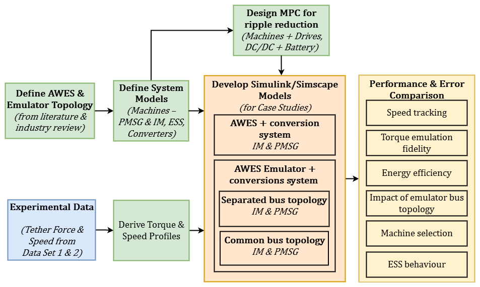
Figure 1Overview of the methodology, showing the workflow from system definition and data processing to simulation and performance evaluation.
2.1 AWES electrical power conversion system and emulator structure
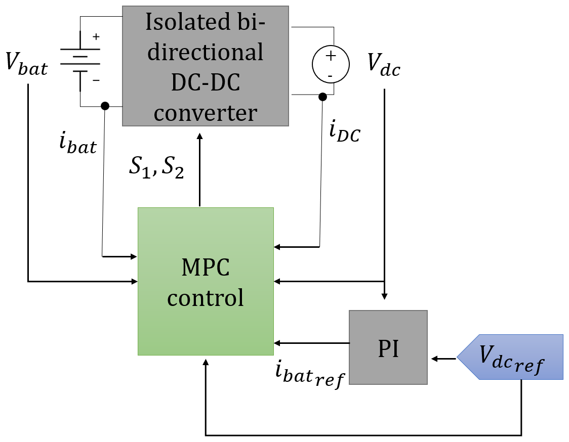
Publicly available, detailed information on specific topologies for mechanical-to-electrical conversion in ground-based airborne wind energy (AWE) systems remains scarce, to the best of the authors' knowledge. This is largely due to the fact that most existing prototypes are still in a pre-commercial phase. Nevertheless, both academic literature such as Uppal et al. (2021), Stuyts et al. (2015), and Rapp et al. (2019) and available industrial reports such as Kitepower (2024) and SkySails Power GmbH (2024) consistently indicate that an electrical three-phase machine controlled by a power converter is typically employed for the mechanical-to-electrical conversion. Furthermore, the alternating load patterns arising from the reel-in and reel-out phases make direct grid connection particularly challenging. This underlines the need for an energy storage system to smooth power fluctuations and ensure a steady electrical output (Bagaber and Mertens, 2022; Joshi et al., 2022a). This requirement is corroborated by the limited industrial disclosures from leading AWES developers – such as Skysails, Kitepower, and Kitemill – which report the use of DC battery storage in their systems. Drawing on this information, Fig. 2 presents a generalized representation of the most common power conversion process in a ground-station AWES.
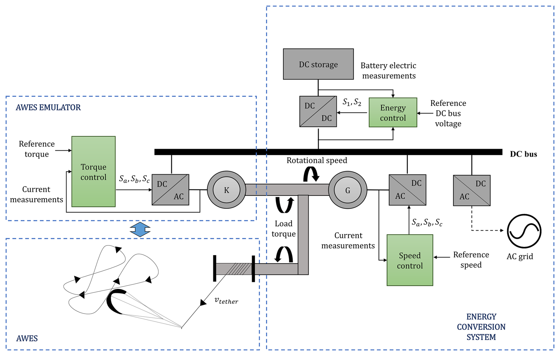
Figure 2Schematic representation of the power conversion process in AWESs, including the AWES emulator, energy conversion system, and control interactions.
Figure 2 illustrates the power conversion process in an AWES; control components are represented in color green for clarity. To optimize mechanical power extraction in an AWES, an electrical machine (G) regulates the kite's reeling speed, vtether, via a DC–AC power converter, ensuring consistent rotation, despite varying tether forces. During the reel-out phase, G operates as a generator, converting mechanical to electrical energy, which is transferred to a high-voltage DC bus. During the reel-in phase, G operates as a motor, spinning in the opposite direction and allowing the tether to retract. A bi-directional DC–DC converter stabilizes the bus voltage by charging a storage device (e.g., a battery) during the reel-out phase and discharging it during the reel-in phase when G functions as a motor to retract the kite. This process ensures efficient energy management and stable system operation during both phases of the AWES cycle. This topology supports both connection to an external AC grid and islanded operation.
The proposed AWES emulator simulates the effect of the changing tether forces on the electric machine shaft using another electrical machine (K) that regulates the shaft load torque via a DC–AC power converter. Precise and robust control of this converter is essential to accurately replicate the kite's mechanical behavior.
2.2 Aerodynamic inputs for AWES power conversion
To maximize mechanical power output during the traction phase of the cycle, an AWES aircraft must follow a closed trajectory in crosswind conditions (Loyd, 1980). Commonly used flight paths include circular and lemniscate (figure-eight) patterns, with the latter offering more consistent tether forces, Ftether, which are advantageous for power generation (Erhard and Strauch, 2015) and for grid integration (Eijkelhof et al., 2024). Along this path, tether forces increase during downward turns and decrease during climbing segments due to variations in apparent wind velocity caused by gravity.
The efficiency of mechanical power generation depends on the reeling factor f, which is defined as
where vtether is the tether reel-out speed and vwind is the wind speed at the wing. The optimal reeling factor, fopt, for straight tethers is given by (Schmehl et al., 2013)
where θ and ϕ are the azimuth and elevation angles of the kite, respectively. These variables are used to calculate the reference torque, Tload, and rotational speed, ωm, for the emulator, which are defined as
where Rdrum is the drum radius and i is the overall gear ratio of the system's drivetrain. For the sake of simplicity, Rdrum is assumed constant and a value of i = 1 is considered for this study.
To better understand how these variables influence the operation of the electrical power conversion system and kite emulator, Fig. 3 illustrates the distribution of time spent at each combination of angular speed and torque values (Tload, ωm) during a reference AWES cycle from Schmehl (2023). The reel-out phase, during which the tether is extended and mechanical power is converted into electrical energy, is characterized by a wide range of operating points. Conversely, in the reel-in phase, where the tether is retracted and energy is consumed to pull the kite back, the torque values exhibit lower variability, and the electrical machine operates as a motor rather than a generator.
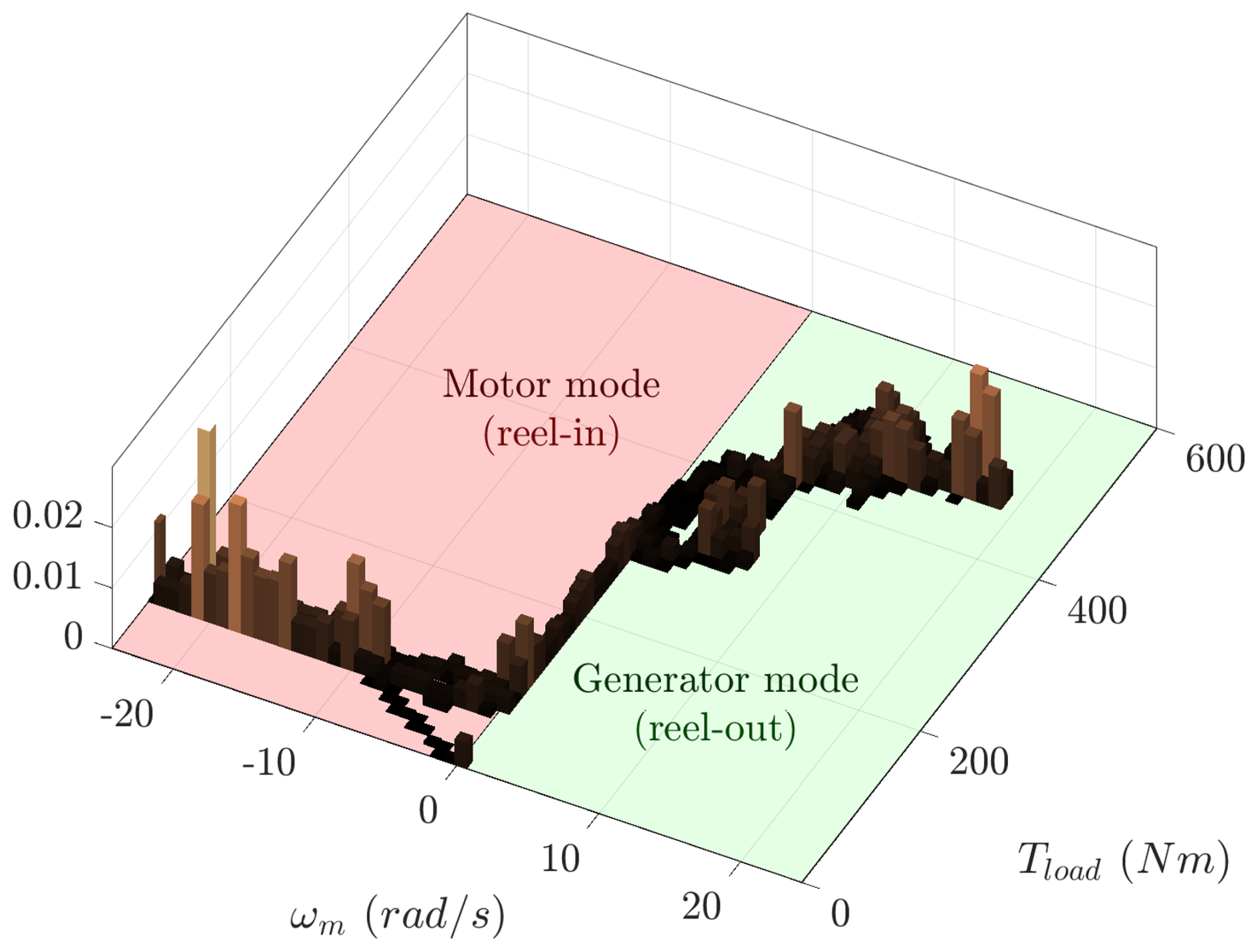
Figure 3Distribution of time spent at each combination of angular speed and torque during the AWES cycle, highlighting the operational differences between the reel-out (generation) and reel-in (motor operation) phases.
2.3 Electric topology for an airborne wind energy system and its test bench emulator
Building on the generalized scheme shown in Fig. 2, in this work we propose a specific implementation for both the AWES ground station and its test bench emulator. The proposed configuration employs a DC battery as the energy storage element, a two-level three-phase DC–AC converter as the machine drive, and a bi-directional DC–DC converter to interface the battery with the DC bus. For the purposes of this study, the system is operated in islanded mode, without connection to an external AC grid.
The electric topology is fundamental for replicating the energy conversion dynamics of an AWES and enabling efficient power flow in the proposed test bench emulator. This section describes the topology for a real AWES and the two emulator configurations designed to simulate its behavior.
2.3.1 Topology for an airborne wind energy system
As shown in Fig. 4a, the proposed topology for a real AWES uses a kite tether wound around a drum connected to a three-phase electrical machine (G). During the reel-out phase, machine G acts as a generator, converting the kite's mechanical energy into electrical energy. During the reel-in phase, it operates as a motor, consuming energy to retract the tether.
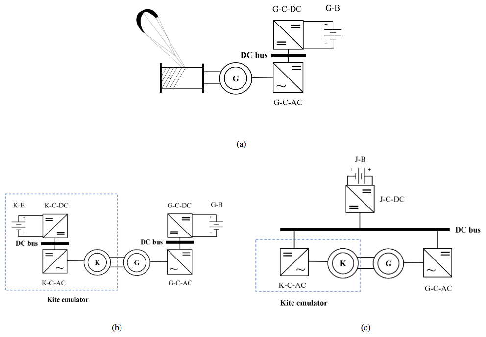
Figure 4Proposed power conversion topologies for the AWES test bench emulator: (a) proposed power conversion topology for a real AWES, (b) proposed dual-DC-bus topology approach for the AWES electrical emulator, and (c) proposed common-DC-bus topology approach for the AWES electrical emulator.
Machine G is controlled by a DC–AC converter (G-C-AC) to manage power flow, while the generated energy is stored in a battery (G-B) via a DC–DC converter (G-C-DC). The system's power generation and consumption are governed by the kite's flight dynamics, which dictate the torque applied to the drum.
2.3.2 Proposed emulator topologies
The AWES test bench emulator simulates the interaction between the kite and the generator using an additional three-phase electrical machine (K), mechanically coupled to machine G. Machine K operates in opposition to G, acting as a motor during the reel-out phase to emulate the kite's mechanical forces and as a generator during the reel-in phase to recover the mechanical energy applied by G. Two topologies are proposed in Fig. 4 for the emulator, each tailored to specific testing requirements.
The first topology, shown in Fig. 4b, uses two separate DC buses. Machine G connects to its own battery (G-B) through a DC–DC converter (G-C-DC) to store energy generated during the reel-out phase. Similarly, machine K is powered by a separate battery (K-B) through its own DC–DC converter (K-C-DC). This configuration closely replicates the energy storage and flow dynamics of a real AWES, making it ideal for studying energy storage requirements. However, it increases system complexity by requiring two batteries and two DC–DC converters.
The second topology, illustrated in Fig. 4c, simplifies the system by using a common DC bus shared by machines G and K. A single battery (J-B) and a single DC–DC converter (J-C-DC) manage energy storage. During the reel-out phase, energy generated by G is recirculated directly to K, reducing battery usage. This topology is more efficient and cost-effective, particularly for extended tests, but it sacrifices accuracy in emulating the distinct energy storage dynamics of a real AWES.
2.4 Model predictive control strategy
The control scheme for the power converters is designed to address the dynamic and multi-variable nature of AWESs. Compared to conventional wind energy systems, AWESs are characterized by lower inertia, exposure to higher and more unpredictable wind conditions, and a highly variable flight cycle profile. These unique features demand a control strategy capable of rapid adjustments and robust performance under changing operating conditions.
MPC was selected for its capability to manage constraints, non-linearities, and fast-changing dynamics. Its excellent steady-state performance and rapid dynamic response make it particularly well suited for AWES applications, where precise regulation of torque and energy flow is critical (Zhang et al., 2016; Hosseinzadeh et al., 2018). In addition, extensive benchmarking in related high-performance drive applications has shown that MPC can outperform conventional strategies such as field-oriented control (FOC) and direct torque control (DTC) in terms of torque tracking, current ripple, and efficiency (Rodriguez et al., 2022; Wang et al., 2018). These findings from the broader literature provide indirect but strong evidence of MPC's superiority, supporting its use in this study. This section outlines the implementation of MPC for regulating the power converters in the proposed topologies (as shown in Sect. 2.3). Key features include a ripple optimization strategy that minimizes fluctuations in controlled variables, ensuring that the kite emulator accurately reproduces the dynamic torque profile of a real AWES. Figure 5 illustrates the generalized structure of the MPC applied to a power converter, with specific details on its implementation for each system component provided in subsequent sections.
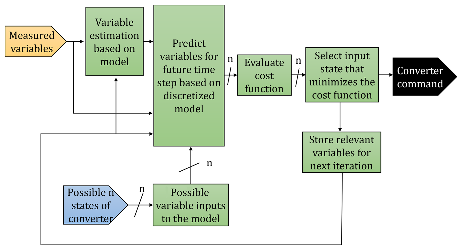
2.4.1 MPC ripple optimization vector strategy
The ripple optimization strategy is a critical enhancement of the proposed MPC, designed to minimize fluctuations in the controlled variables and improve the fidelity of the kite emulator. The MPC algorithm determines the switching states of either the bi-directional DC–DC converter or the two-level three-phase DC–AC converter. For the DC–DC converter, there are n = 2 possible states, while for the DC–AC converter n = 7 due to redundant states that produce the same voltage vector (Rodriguez et al., 2007). The selection of input states directly impacts the system's performance, particularly the accuracy of torque reference tracking and ripple suppression.
Two state selection strategies are evaluated:
-
Classical Si strategy. This conventional approach selects a single optimal state Si (e.g., S0 to S6 for the DC–AC converter and S0 to S1 for the DC–DC converter) that minimizes the error between the predicted and reference output variables over the entire sampling period Ts. Once selected, this state remains constant throughout Ts. While computationally simple, this strategy can lead to higher ripple in the controlled variables, as it does not adjust for intermediate changes within Ts.
-
Symmetrical strategy. This enhanced approach introduces a three-state symmetric input sequence () to achieve finer control of the output variables. The controller calculates the fraction of Ts during which Si will be applied using a discrete parameter fduty, which divides Ts into three intervals:
Predefined discrete values for fduty are . Unlike the classical strategy, this method predicts the output variables at three points within Ts (T1, T2, and T3), enabling a closer match to the reference values.
The symmetrical Si, S0, Si strategy provides notable benefits, including reduced ripple in controlled variables, enhanced torque precision, and lower switching frequency. These advantages stem from the inclusion of the intermediate state S0, which smooths transitions between Si states, as shown in Fig. 6. While this approach incurs a slightly higher computational cost, it is well supported by modern microcontrollers (Yu and Long, 2024).
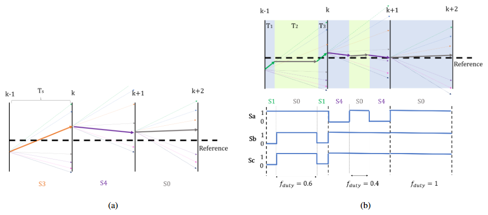
Figure 6Comparison of MPC input vector strategies for three sample periods: (a) single input vector Si strategy and (b) symmetrical Si, S0, Si input vector strategy.
The comparison in Fig. 6 highlights the superior performance of the Si, S0, Si strategy in suppressing ripple and achieving greater accuracy over multiple sampling periods. This optimized strategy plays a vital role in ensuring that the kite emulator accurately replicates the dynamic torque profile of an actual AWES.
2.4.2 Model predictive control discretization
The discretization of the system models is essential for implementing MPC. Each component of the system is described in terms of discrete-time equations, enabling the MPC to predict and optimize the control variables. The number of switching states (n), and consequently the number of possible input variables for the model (as shown in Fig. 5), is determined by the type of converter being controlled: n = 7 for a two-level three-phase DC–AC converter, which maps to seven distinct stator voltage vectors Vs, and n = 2 for a bi-directional DC–DC converter with two switching states. This section details the discretization process for IM and PMSG, as well as the bi-directional DC–DC converter.
Induction machine
The induction machine's electrical model is expressed in matrix form as follows:
Here, v, s, and r are vectors containing the system variables, including space vectors for the stator voltage , stator flux , stator current , rotor flux , and rotor current , as shown in Eq. (8).
The values for matrices A, B, C, and D are provided in Appendix A.
The electromagnetic torque Te is computed as
where p is the number of pole pairs and Im{…} denotes the imaginary part of a complex number.
The model is discretized using the forward Euler method (Butcher, 2016):
The matrices Av and As are calculated as
where Ts is the sampling time and I is the identity matrix.
Permanent magnet synchronous generator
The PMSG is modeled in the synchronous reference frame as
where , , and are the space vectors for the stator voltage, stator current, and magnetic flux, respectively, defined as
The values for matrices F, G, and L are provided in Appendix B.
The forward Euler method is applied to discretize the current space vector:
where the matrices are
The electromagnetic torque is calculated as
where Ld and Lq are the d-axis and q-axis inductances, and φm is the permanent magnet flux linkage.
Bi-directional DC–DC converter
The bi-directional DC–DC converter is modeled as
where g and m are vectors defined as
Here, Vdc is the DC-bus voltage, iL is the inductor current of the converter, Vbat is the battery voltage, and Idc is the DC-bus current.
The matrices S and H are defined as
where the variable s1 represents the state of the bi-directional DC–DC converter's top switch (either 1 or 0), and the number of possible states, n, in this case is 2. The parameter C1 represents the capacitance on the DC-bus side of the converter, while L corresponds to the converter's inductance.
Discretizing with the forward Euler method gives
where Am and Ag are the system matrices
The discretization simplifies the control implementation while maintaining the model's dynamic accuracy.
2.4.3 Control of the generating machine DC–AC converter (G-C-AC)
The G-C-AC converter ensures the electrical machine tracks the commanded rotational speed regardless of load torque. A proportional-integral (PI) controller calculates the reference electromagnetic torque, , from the mechanical speed error, which is then used by the MPC as a reference.
For the induction machine (IM), the MPC employs the discretized model seen in Sect. 2.4.2 and minimizes the normalized errors of the stator flux and torque, as shown in the cost function:
where λφ and λT are weighting factors and and are base values used for normalization.
For the PMSG, the MPC focuses on minimizing the torque error and reducing the d-axis stator current to enhance efficiency:
where λi and λT are weighting factors and and are base values used for normalization.
Control diagrams for both machine types are shown in Fig. 7.
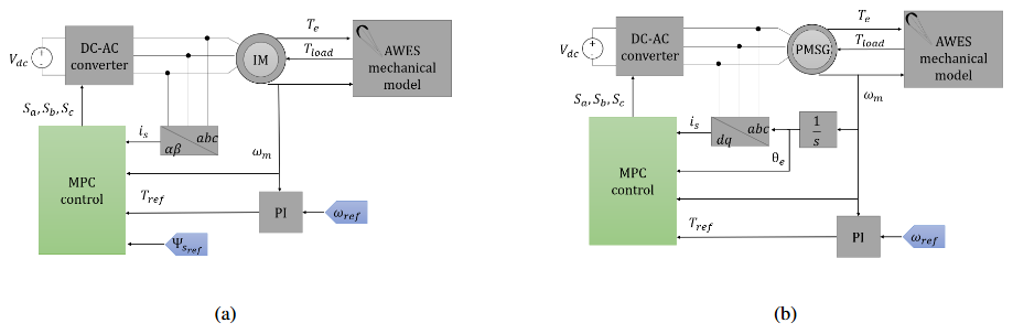
Figure 7Control schemes for the generator machine DC–AC converter (G-C-AC): (a) control scheme when an induction machine is used and (b) control scheme when a permanent magnet synchronous generator is used.
2.4.4 Control of the kite emulator machine DC–AC converter (K-C-AC)
The K-C-AC converter applies a reference torque to emulate the kite's mechanical behavior during the AWES cycle. This torque is computed using the single-mass mechanical model:
where Jeq is the equivalent inertia, Te is the electromagnetic torque, and Tload is the load torque.
Similar to the G-C-AC, the MPC for the K-C-AC uses the machine's discretized model and minimizes reference variable errors according to Eq. (26) for the IM and Eq. (27) for the PMSG. Control schemes for the IM and PMSG implementations are presented in Fig. 8.
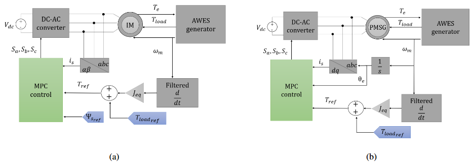
Figure 8Control schemes for the emulator machine DC–AC converter (K-C-AC): (a) control scheme when an induction machine is used and (b) control scheme when a permanent magnet synchronous generator is used.
2.4.5 Control of the DC–DC converter
The DC–DC converter maintains a constant DC-bus voltage by regulating power flow between the battery and the DC bus. The MPC uses measured currents and voltages to minimize the normalized errors in battery current (iL) and DC-bus voltage (Vdc) using the cost function:
where and λv are weighting factors and and are base values used for normalization. The control scheme for the DC–DC converter maintaining a stable DC bus is found in Fig. 9
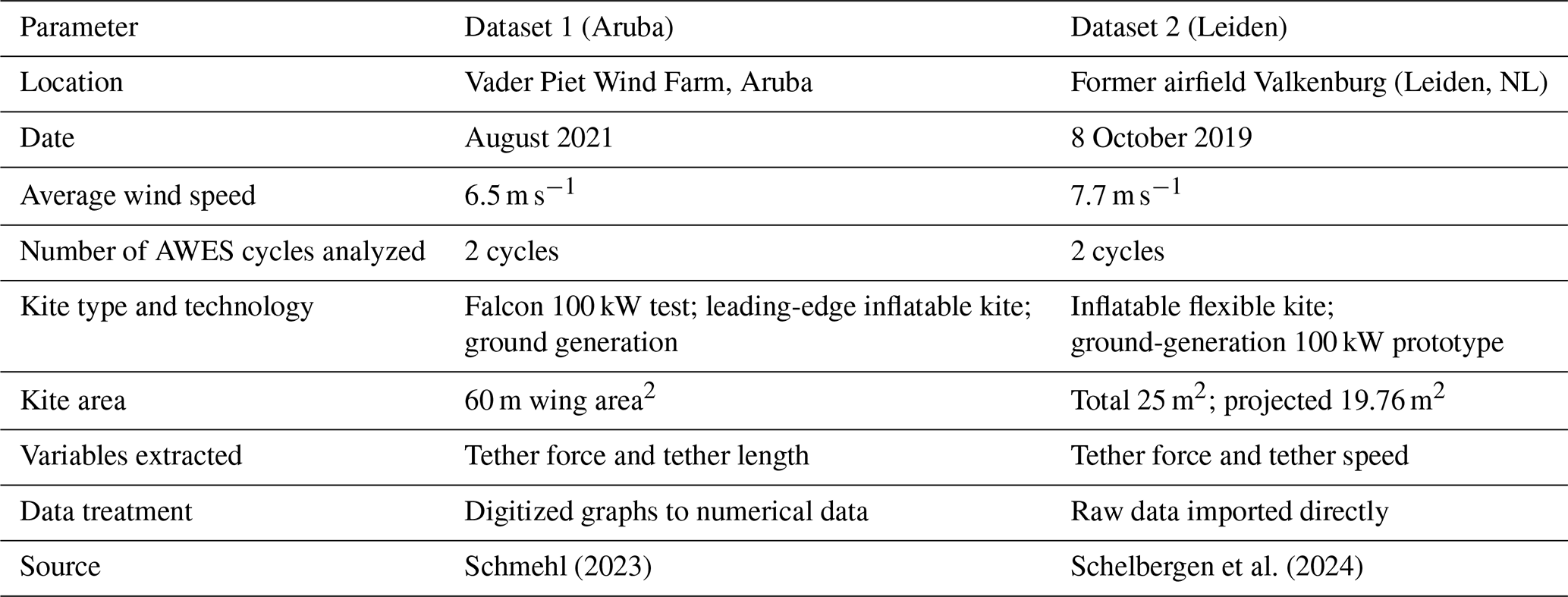
The validation of the AWES electric emulator topology and the proposed MPC control was carried out using two publicly available Kitepower flight datasets, as summarized in Table 1. Dataset 1 (Aruba) provides digitized time series of tether force and tether length for two AWES cycles recorded at Vader Piet Wind Farm in August 2021 (Schmehl, 2023). Dataset 2 (Leiden) contains raw measurements of tether force and tether speed for two AWES cycles recorded at the former Valkenburg airfield in October 2019 (Schelbergen et al., 2024).
Schmehl (2023)Schelbergen et al. (2024)Table 1Summary of publicly available Kitepower datasets used in this study.
In both datasets, the recorded linear variables were translated into equivalent torque and rotational speed reference signals for the emulator using the methodology described in Sect. 2.2, assuming a drum radius of Rdrum = 0.2 m. This procedure ensures that the emulator operates under representative mechanical conditions derived from actual AWES operation, enabling a consistent evaluation of control performance across the two datasets.
3.1 Case study and test environment
The evaluation was carried out in two stages using the mechanical profiles from the two datasets summarized in Table 1. For each dataset, reference profiles of the optimum reel-out and reel-in speeds, together with the corresponding torque acting on the generator, were derived for two complete AWES cycles.
In the first stage, the mechanical-to-electrical power conversion system shown in Fig. 4a was tested using these reference profiles. The generator was commanded to follow the optimum reel-out and reel-in speed profile from the dataset, while the electrical machine experienced the corresponding reference torque profile. This configuration was tested for two machine types: an induction machine and a permanent magnet synchronous generator.
In the second stage, the two emulator topologies shown in Fig. 4b and c were evaluated using the same datasets. In these configurations, the generator machine was again commanded to follow the reference speed profile, while the emulator machine was torque-controlled to reproduce the reference torque profile corresponding to the AWES operation. Both IM and PMSG machines were used in various combinations for the emulator tests. All analyses in both stages were repeated for each of the two datasets in order to enable consistent performance comparison across different operating conditions.
The tests were conducted in the MATLAB/Simulink environment, with all electrical hardware modeled using Simscape Electrical. Parameters for modeling and control are detailed in Appendix C.
3.2 Control objectives and performance indicators
The main objectives of the proposed MPC control, along with their corresponding performance metrics, are as follows:
-
Accurate torque tracking with minimal ripple. Ensure that the kite emulator machine precisely follows the reference load torque of the AWES while minimizing electromagnetic torque ripple. Performance is evaluated using the RMSE between the measured load torque on the shaft and the reference torque from the AWES dynamic profile.
-
Precise speed regulation of the generator machine. Maintain accurate tracking of the optimal reference speed during both transient and steady-state operation. This is assessed using the normalized RMSE between the measured mechanical shaft speed and the reference speed from the AWES dynamic profile.
-
Maximization of energy conversion efficiency. Optimize the total electrical energy extracted from the available mechanical energy of the AWES cycle. Efficiency is quantified as the ratio of total energy stored in the battery to the total mechanical energy generated by the kite.
-
Stable and regulated DC-bus voltage. Ensure a steady and well-regulated DC-bus voltage throughout operation. This is evaluated using the normalized RMSE between the measured DC-bus voltage and the reference voltage.
This section presents the performance evaluation of the proposed AWES test bench emulator for the two proposed datasets, highlighting its ability to replicate the dynamic behavior of a real AWES. Key numerical performance metrics are summarized in Tables 2 and 3. Experimental results for the kite emulator and generator dynamics are detailed in Figs. 10 and 11, focusing on the torque, speed, and power profiles for two optimal figure-eight AWES cycles.
4.1 Numerical performance metrics
4.1.1 Dataset 1
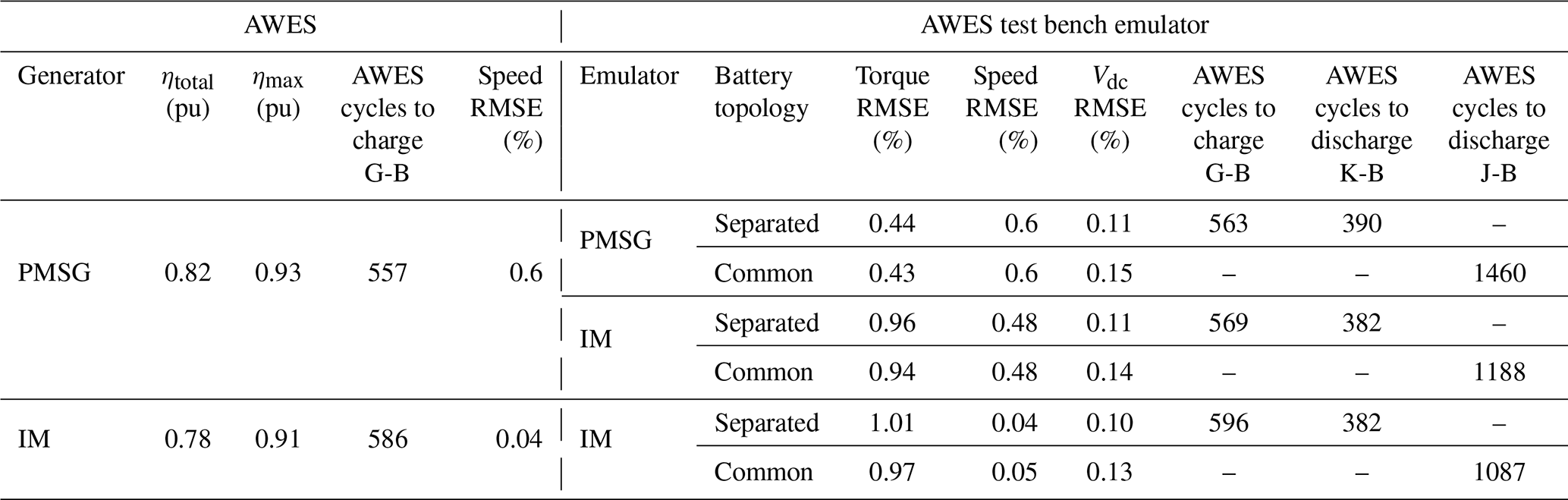
Table 2 summarizes the numerical performance metrics obtained when applying the mechanical profiles from Dataset 1 (Aruba). The table reports the overall and maximum energy efficiencies (ηtotal and ηmax) for both generator types, as well as root mean square errors (RMSE) for speed, torque, and DC-bus voltage. In addition, battery performance is characterized by the number of AWES cycles required to charge or discharge the batteries under both separated- and common-DC-bus topologies. The PMSG configuration achieves slightly higher efficiency, particularly during reel-in phases, whereas the IM configuration exhibits comparable tracking accuracy in speed and torque.
Table 2Performance evaluation for Dataset 1 (Aruba) across generator types and emulator topologies.
4.1.2 Dataset 2
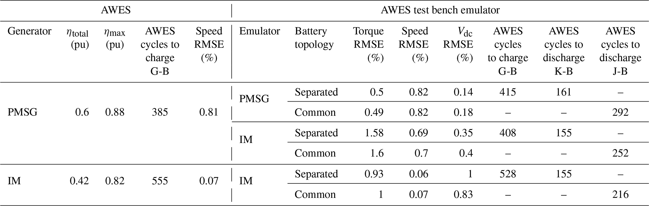
A parallel evaluation was performed using the mechanical profiles from Dataset 2 (Leiden). The same performance indicators are reported in Table 3, following the structure used for Dataset 1. PMSG again demonstrates higher energy efficiency compared to IM, while IM offers marginally improved speed tracking. Torque tracking errors are slightly higher for both machines compared with the results from Dataset 1, likely due to the more dynamic nature of this dataset. Overall, both configurations exhibit reduced global efficiency, as the operating points deviate further from the machines' nominal torque and speed ratings.
Table 3Performance evaluation for Dataset 2 (Leiden) across generator types and emulator topologies.
4.2 Emulated mechanical dynamics
4.2.1 Dataset 1
Figure 10 illustrates the performance of the AWES emulator for two optimal figure-eight cycles when using PMSG machines for both the generator and the kite emulator for Dataset 1. In Fig. 10a, the torque applied by the emulator closely reproduces the reference torque profile from the real AWES, with low ripple and high accuracy. Figure 10b demonstrates that the generator tracks the commanded optimal rotational speed with a root mean square error below 1 %. The results correspond to the separated-DC-bus configuration; the corresponding torque and speed profiles for the common-DC-bus configuration were found to be nearly identical, indicating that the bus topology has minimal influence on these dynamic variables.
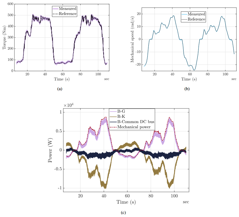
Figure 10Case study results for two optimal figure-eight cycles of the AWES emulator using PMSG machines from Dataset 1 (Aruba): (a) emulated kite torque, (b) mechanical speed of the system, and (c) filtered power readings for the generator and emulator batteries.
4.2.2 Dataset 2
A parallel evaluation was conducted using the profiles from Dataset 2 (Leiden). Figure 11 follows the same layout as that used for Dataset 1 and illustrates the torque tracking, speed tracking, and filtered power readings. Similar to the results shown for Dataset 1, the proposed control strategy enables the emulator to closely reproduce the torque profile from the AWES with low ripple and high accuracy, while the generator accurately tracks the reference speed. As with Dataset 1, the torque and speed profiles shown correspond to the separated-DC-bus configuration, since the results obtained with the common-DC-bus configuration were found to be nearly identical.
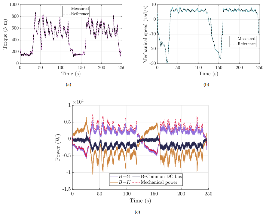
Figure 11Case study results for two optimal figure-eight cycles of the AWES emulator using PMSG machines from Dataset 2 (Leiden): (a) emulated kite torque, (b) mechanical speed of the system, and (c) filtered power readings for the generator and emulator batteries.
4.3 Battery performance, power profiles, and efficiency analysis
The filtered power profiles in Fig. 10c highlight the fundamental differences between our two DC-bus configurations for Dataset 1. In the separated topology, the G-B and K-B legs exhibit distinct charge and discharge waves, closely matching true AWES battery cycling. By contrast, the common DC bus redirects most generated energy back into the machine emulator, yielding a near-zero net bus flow, so that under these test conditions the battery sees only small net transfers. This internal recirculation, for this dataset, reduces battery wear and delivers roughly 280 %–370 % more cycles per charge, making it ideal for rapid, repeatable electric machine control-strategy tuning. It is not intended to mimic a real grid-tied system, where excess power would be exported via a grid-tie converter, but rather to offer a low-degradation test mode. For studies focused on realistic storage dynamics (for example battery sizing, round-trip efficiency, or state-of-charge effects) the separated-bus layout remains the preferred choice.
When the same evaluation is performed using Dataset 2 (see Fig. 11c), both electrical machines exhibit significantly lower global efficiency. This reduction is attributed to the operating points in Dataset 2 being further from the machines' nominal torque and speed regions, where electrical machines typically perform less efficiently. Under these conditions, the separated-bus topology remains the only configuration that accurately reproduces realistic storage dynamics. However, the common-bus topology still offers a reduced hardware requirement, using fewer converters and batteries, and although the battery-cycling reduction is less pronounced than in Dataset 1, it continues to require fewer charge–discharge cycles than the separated-bus configuration. It therefore remains the preferred option for repeated test campaigns where only the emulation of electrical machine dynamics is relevant and storage behavior is not under study.
To summarize these trade-offs and to make the discussion clearer for the reader, Table 4 provides a concise side-by-side comparison of both topologies. It highlights the hardware requirements, fidelity to actual AWES storage behavior and machine dynamics, the efficiency-dependent battery-cycling characteristics observed in both datasets, and the type of studies each configuration is best suited for.
Table 4Comparison of separated- and common-DC-bus configurations.
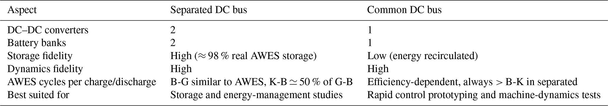
Figure 12 shows the instantaneous efficiency profiles of IM and PMSG machines during the generating (reel-out) phase for both datasets. In Dataset 1 (Fig. 12a), PMSG consistently outperforms IM at low power levels, with a maximum efficiency difference of about 6 %. At higher power levels, both machines reach similar efficiencies, with differences below 2 %. For Dataset 2 (Fig. 12b), overall efficiencies for both machines are lower, consistent with operation at points further from their nominal ratings. The efficiency gap between PMSG and IM remains visible and is more pronounced, though still below 10 %. An increase in power ripple also appears to affect partial efficiencies, contributing to the larger fluctuations seen in the efficiency profiles.
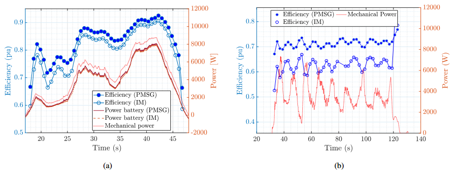
Figure 12Instantaneous energy efficiency of the power conversion system during the generating phase of one AWES cycle: (a) for Dataset 1 and (b) for Dataset 2.
This paper presents a validated electric topology and torque ripple – optimizing MPC strategy for an airborne wind energy system generator and its corresponding test bench electrical emulator. While extensive research has focused on optimizing AWES flight trajectories and aerodynamic performance, the mechanical-to-electrical power conversion process remains underexplored. This study addresses that gap by reviewing key AWES power conversion architectures and validating an efficient control framework using experimental data from two AWES flight cycles: Dataset 1 recorded in Aruba and Dataset 2 recorded in Leiden.
The proposed electric topology and MPC control effectively convert the mechanical energy extracted from an optimal AWES flight path into electrical energy, achieving a total system efficiency of 82 % for Dataset 1 (Aruba) and 60 % for Dataset 2 (Leiden), with maximum instantaneous efficiencies of 93 % and 88 %, respectively. The system maintains precise speed control, tracking the reference rotational speed within 0.44 % RMSE for Dataset 1 and 0.82 % RMSE for Dataset 2, and the emulator tracks the reference torque with 0.11 % and 0.14 % RMSE, respectively. Across both datasets, permanent magnet synchronous generators outperform induction machines, achieving 4 % higher total energy efficiency in Dataset 1 and an even larger – but still under 20 % – efficiency gap in Dataset 2, with instantaneous efficiency improvements of 2 %–6 % in high-efficiency regions.
The test bench emulator accurately reproduces AWES mechanical dynamics, providing a controlled environment for evaluating power conversion and control strategies. The separated-DC-bus topology achieves about 98 % fidelity in replicating real AWES storage dynamics but requires 45 %–55 % greater battery capacity for the emulator, making it the preferred configuration when studying energy management or storage behavior. By contrast, the common-DC-bus topology recirculates energy between the generator and emulator, reducing battery requirements by roughly two-thirds. Although it does not reproduce detailed storage operation, it enables long-duration, repeated machine-dynamics tests with minimal battery cycling.
Across both datasets, operating the electrical machines outside their nominal region results in a degradation of AWES cycle efficiency, highlighting the critical importance of proper machine dimensioning. Reduced conversion efficiency in off-nominal regions drives significantly higher battery cycling even under a common-bus setup. Nevertheless, if, and only if, storage dynamics are not under study and only machine dynamics are required, the common-bus configuration is the most cost-effective solution, using less hardware and imposing lower peak discharge stresses than the separated configuration.
These findings highlight the effectiveness and versatility of the proposed AWES power conversion strategies and emulator. By bridging a gap in AWES research, this work provides a foundation for integrating mechanical and electrical efficiency considerations into AWES system design, making it highly relevant to both power system and flight control researchers.
Future work should focus on co-optimizing flight trajectories and power conversion strategies, exploring efficiency gains at varying power levels, and expanding the test bench framework to support grid integration and larger-scale AWES applications. In addition, the proposed control strategy should be benchmarked against alternative control approaches to further validate its relative performance. Experimental validation is also required to strengthen and build upon the design conclusions presented here. Finally, when detailed ground-station models become available, incorporating a more specific mechanical model to estimate rotational variables from tether length and speed data would enhance the fidelity of the emulator and improve the applicability of the results.
The following matrices define the state-space representation of the induction motor (IM) model in a stationary reference frame. In these matrices, Rs and Rr represent the stator and rotor resistances, respectively, while Ls, Lr, and Lm denote the stator, rotor, and magnetizing inductances. The parameter ωe corresponds to the electrical angular speed of the rotor.
The following matrices describe the state-space representation of the PMSG model in a rotating direct-quadrature (dq) reference frame. Here, Rs represents the stator resistance, while Ld and Lq correspond to the direct-axis and quadrature-axis inductances. The parameter ωe denotes the electrical angular speed of the rotor.
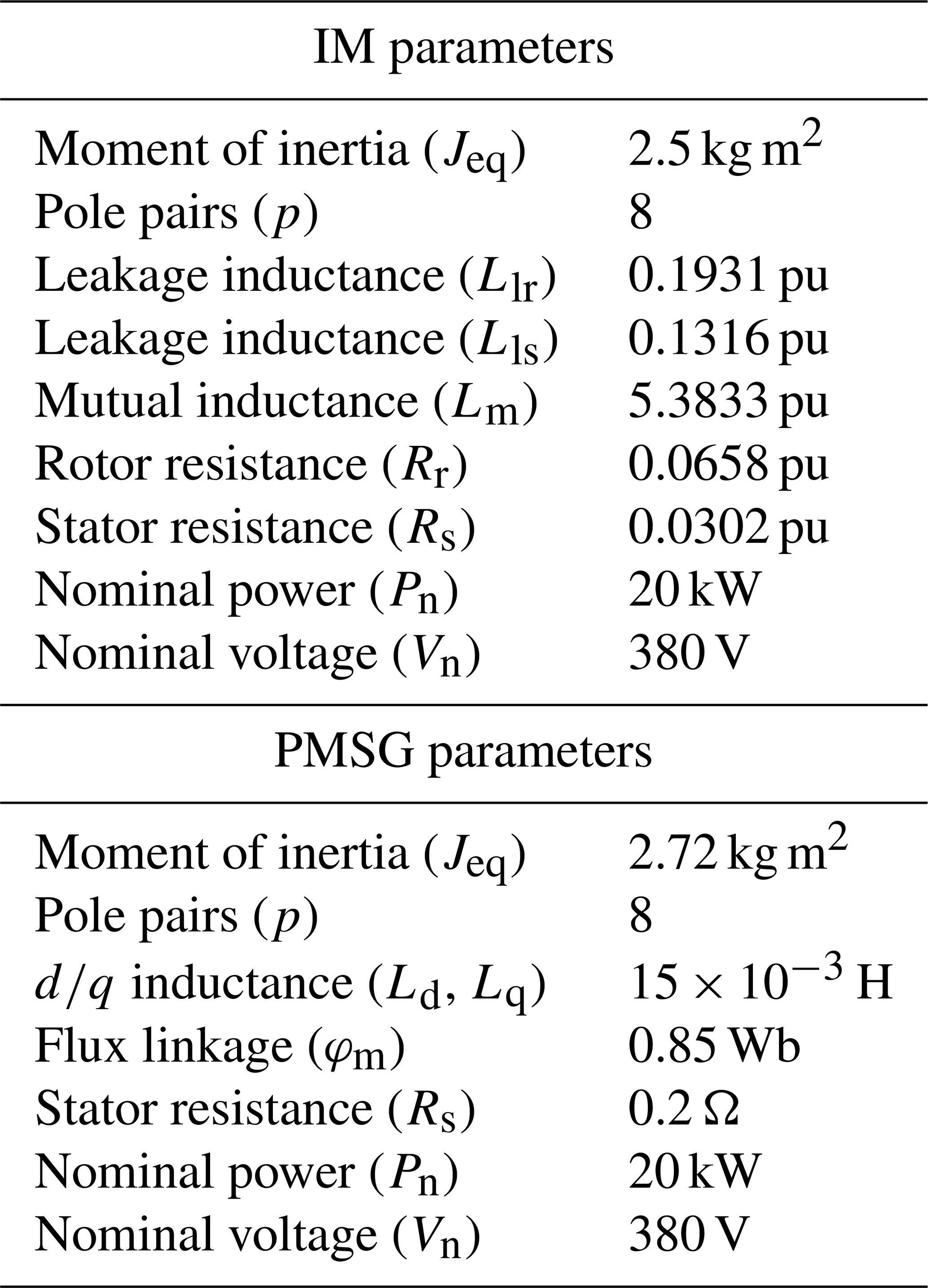
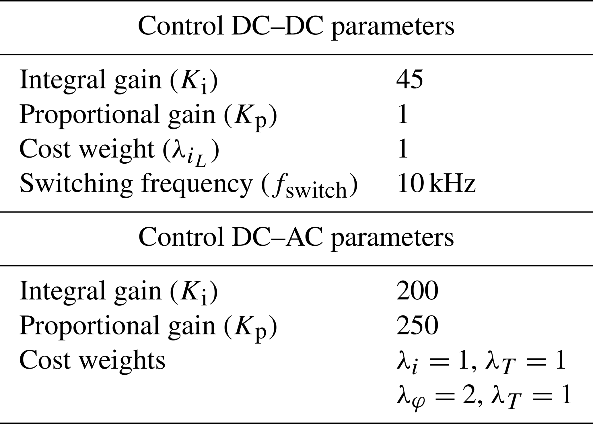
This section summarizes the key electrical and control parameters used in the case study, including battery specifications, converter characteristics, and machine properties. These values define the operational limits and dynamic behavior of the AWES test bench emulator.
The PMSG and IM parameters used in this study (see Table C3) were adapted from well-established designs for 10–30 kW class wind energy machines, which align with those implemented in early AWES prototypes and laboratory test benches (Ebrahimi Salari et al., 2016). Ground-generation systems such as the Ampyx 12 kW and TU Delft 20 kW platforms demonstrate similar operating ranges and machine characteristics, supporting their suitability for emulating AWES dynamics. These parameters are consistent with values reported in wind energy literature for machines of comparable scale (Yaramasu and Wu, 2016), ensuring the emulator reflects realistic hardware while allowing future updates as more AWES-specific data become available.
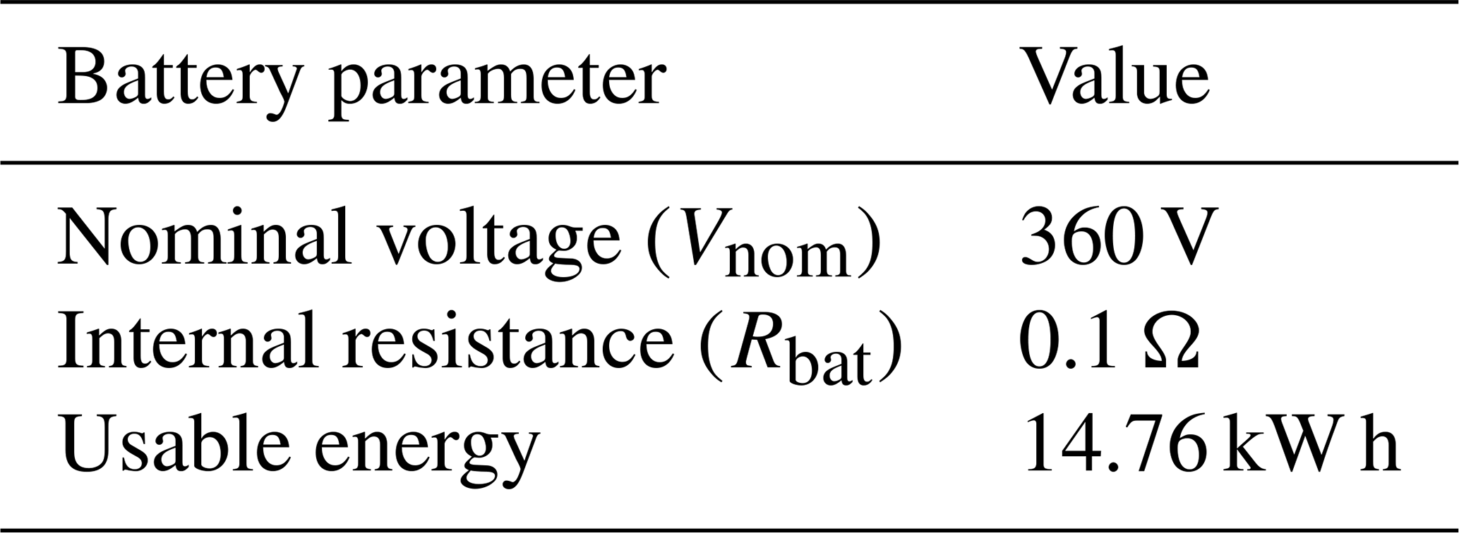
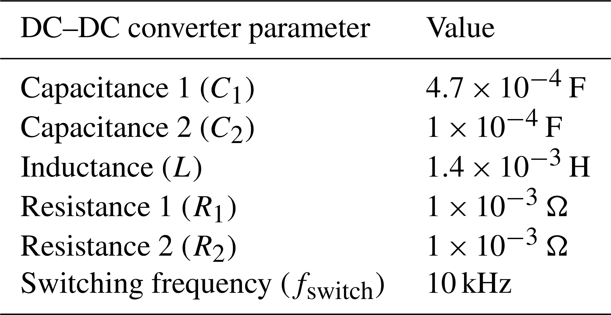
Table C3Parameters for induction machine and permanent magnet synchronous generator.
The MATLAB and Simulink source code developed for this study is publicly available on Zenodo: https://doi.org/10.5281/zenodo.17312516 (Martín, 2025). The repository includes the simulation models, control scripts, and post-processing routines supporting all results presented in this work.
The datasets required to reproduce the results of this study are included in the same public repository on Zenodo: https://doi.org/10.5281/zenodo.17312516 (Martín, 2025). The archive contains the .mat files used for the case studies, as well as the original airborne wind energy system (AWES) flight data obtained from publicly available sources cited in the manuscript (Kitepower “Aruba” and “Leiden” datasets).
DS and CN: conceptualization. CN, DS, FD, and JG: methodology. CN: software. CN: validation. CN and FD: formal analysis. CN: investigation. DS: resources. CN and JG: data curation. CN and FD: writing – original draft preparation. CN, FD, DS, and JG: writing – review and editing. CN, DS, FD, and JG: visualization. DS: supervision and project administration. All authors have read and agreed to the published version of the manuscript.
The contact author has declared that none of the authors has any competing interests.
Publisher's note: Copernicus Publications remains neutral with regard to jurisdictional claims made in the text, published maps, institutional affiliations, or any other geographical representation in this paper. While Copernicus Publications makes every effort to include appropriate place names, the final responsibility lies with the authors. Views expressed in the text are those of the authors and do not necessarily reflect the views of the publisher.
This work is part of the project PID2022-141520OB-I00 funded by MICIU/AEI/ https://doi.org/10.13039/501100011033. Work by Francisco DeLosRíos-Navarrete was supported by the grant with reference IND2022/AMB-23521 funded by Comunidad de Madrid. AI tools have been used exclusively to proofread and format specific parts of the manuscript.
This research has been supported by Comunidad de Madrid (grant no. IND2022/AMB-23521) and MICIU/AEI/10.13039/501100011033 (grant no. PID2022-141520OB-I00).
This paper was edited by Amir R. Nejad and reviewed by two anonymous referees.
Bagaber, B. and Mertens, A.: Energy Storage Systems for Airborne Wind Generators, in: 2022 24th European Conference on Power Electronics and Applications (EPE'22 ECCE Europe), 5–9 September 2022, Hanover, Germany, IEEE, 1–11, electronic ISBN: 978-9-0758-1539-9, ISBN: 978-1-6654-8700-9, 2022. a
Bagaber, B., Junge, P., and Mertens, A.: Lifetime Estimation and Dimensioning of the Machine-Side Converter for Pumping-Cycle Airborne Wind Energy System, in: 2020 22nd European Conference on Power Electronics and Applications (EPE'20 ECCE Europe), IEEE, P.1–P.10, https://doi.org/10.23919/EPE20ECCEEurope43536.2020.9215594, 2020. a
Bechtle, P., Schelbergen, M., Schmehl, R., Zillmann, U., and Watson, S.: Airborne wind energy resource analysis, Renew. Energ., 141, 1103–1116, https://doi.org/10.1016/j.renene.2019.03.118, 2019. a
Butcher, J. C.: Numerical methods for ordinary differential equations, John Wiley & Sons, ISBN: 9781119121503, 2016. a
Castro-Fernández, I., DeLosRíos-Navarrete, F., Borobia-Moreno, R., Fernández-Jiménez, M., García-Cousillas, H., Zas-Bustingorri, M., Ghobaissi, A. T., López-Vega, F., Best, K., Cavallaro, R., and Sánchez-Arriaga, G.: Automatic testbed with a visual motion tracking system for airborne wind energy applications, Wind Energy, 26, 388–401, https://doi.org/10.1002/we.2805, 2023. a
Coleman, J., Ahmad, H., Pican, E., and Toal, D.: Modelling of a synchronous offshore pumping mode airborne wind energy farm, Energy, 71, 569–578, 2014. a
Ebrahimi Salari, M., Coleman, J., and Toal, D.: Airborne wind energy – A review, in: 3rd International Congress on Energy Efficiency and Energy Related Materials (ENEFM2015) Proceedings, Oludeniz, Turkey, 19–23 October 2015, Springer, 81–92, https://doi.org/10.1007/978-3-319-45677-5_10, 2016. a
Ebrahimi Salari, M., Coleman, J., and Toal, D.: Power Control of Direct Interconnection Technique for Airborne Wind Energy Systems, Energies, 11, 3134, https://doi.org/10.3390/en11113134, 2018. a
Eijkelhof, D., Rossi, N., and Schmehl, R.: Optimal Flight Pattern Debate for Airborne Wind Energy Systems: Circular or Figure-of-eight?, Wind Energ. Sci. Discuss. [preprint], https://doi.org/10.5194/wes-2024-139, in review, 2024. a
Erhard, M. and Strauch, H.: Flight control of tethered kites in autonomous pumping cycles for airborne wind energy, Control Eng. Pract., 40, 13–26, https://doi.org/10.1016/j.conengprac.2015.03.001, 2015. a
Fagiano, L., Zgraggen, A. U., Morari, M., and Khammash, M.: Automatic Crosswind Flight of Tethered Wings for Airborne Wind Energy: Modeling, Control Design, and Experimental Results, IEEE T. Contr. Syst. T., 22, 1433–1447, https://doi.org/10.1109/TCST.2013.2279592, 2014. a
Fagiano, L., Nguyen-Van, E., Rager, F., Schnez, S., and Ohler, C.: Autonomous Takeoff and Flight of a Tethered Aircraft for Airborne Wind Energy, IEEE T. Contr. Syst. T., 26, 151–166, https://doi.org/10.1109/TCST.2017.2661825, 2018. a
Fagiano, L., Quack, M., Bauer, F., Carnel, L., and Oland, E.: Autonomous airborne wind energy systems: accomplishments and challenges, Annual Review of Control, Robotics, and Autonomous Systems, 5, 603–631, 2022. a
Freeman, J., Roberts, O., Fiffick, J., Baring-Gould, E., Musial, W., and Duffy, M.: Airborne Wind Energy, Tech. Rep. NREL/TP-5000-79992, National Renewable Energy Laboratory (NREL), NREL/TP-5000-79992, https://docs.nrel.gov/docs/fy21osti/79992.pdf (last access: 10 January 2025), 2021. a
Hagen, L. v., Petrick, K., Wilhelm, S., and Schmehl, R.: Life-Cycle Assessment of a Multi-Megawatt Airborne Wind Energy System, Energies, 16, 1750, https://doi.org/10.3390/en16041750, 2023. a
Hosseinzadeh, M. A., Sarbanzadeh, M., Sarebanzadeh, E., Rivera, M., and Muñoz, J.: Predictive Control in Power Converter Applications: Challenge and Trends, in: 2018 IEEE International Conference on Automation/XXIII Congress of the Chilean Association of Automatic Control (ICA-ACCA), Concepcion, Chile, 17–19 October 2018, IEEE, 1–6, https://doi.org/10.1109/ICA-ACCA.2018.8609704, 2018. a
Joshi, R., Von Terzi, D., Kruijff, M., and Schmehl, R.: Techno-economic analysis of power smoothing solutions for pumping airborne wind energy systems, J. Phys. Conf. Ser., 2265, 042069, https://doi.org/10.1088/1742-6596/2265/4/042069, 2022a. a
Joshi, R., Von Terzi, D., Kruijff, M., and Schmehl, R.: Techno-economic analysis of power smoothing solutions for pumping airborne wind energy systems, J. Phys. Conf. Ser., 2265, 042069, https://doi.org/10.1088/1742-6596/2265/4/042069, 2022b. a
Kitepower: Kitepower - Airborne Wind Energy, https://thekitepower.com/ (last access: 23 October 2023), 2023. a
Kitepower: The Hawk, https://thekitepower.com/the-hawk/#:~:text=Converts%20the%20mechanical%20energy%20of,the%20generator%20as%20a%20motor (last access: 24 July 2025), 2024. a
Kumar, P., Kashyap, Y., Castelino, R. V., Karthikeyan, A., Sharma K., M., Karmakar, D., and Kosmopoulos, P.: Laboratory-Scale Airborne Wind Energy Conversion Emulator Using OPAL-RT Real-Time Simulator, Energies, 16, 6804, https://doi.org/10.3390/en16196804, 2023. a, b
Loyd, M. L.: Crosswind kite power (for large-scale wind power production), J. Energy, 4, 106–111, https://doi.org/10.2514/3.48021, 1980. a, b
Magdy Gamal Eldeeb, H.: Modelling, Control and Post-Fault Operation of Dual Three-phase Drives for Airborne Wind Energy, PhD thesis, Technische Universität München, https://mediatum.ub.tum.de/doc/1464393/1464393.pdf (last access: 15 March 2025), 2019. a
Martín, C. N.: c-nicomar/AWES-test-bench-emulator: Version 1.0 – initial public release (v1.0), Zenodo [data set adn code], https://doi.org/10.5281/zenodo.17312516, 2025. a, b
Pavković, D., Hoić, M., Deur, J., and Petrić, J.: Energy storage systems sizing study for a high-altitude wind energy application, Energy, 76, 91–103, 2014. a
Pavković, D., Cipek, M., Hrgetić, M., and Sedić, A.: Modeling, parameterization and damping optimum-based control system design for an airborne wind energy ground station power plant, Energ. Convers. Manage., 164, 262–276, 2018. a, b
Rapp, S., Schmehl, R., Oland, E., and Haas, T.: Cascaded Pumping Cycle Control for Rigid Wing Airborne Wind Energy Systems, J. Guid. Control Dynam., 42, 1–18, https://doi.org/10.2514/1.G004246, 2019. a
Rodriguez, J., Pontt, J., Silva, C., Correa, P., Lezana Illesca, P., Cortes, P., and Ammann, U.: Predictive Current Control of a Voltage Source Inverter, IEEE T. Ind. Electron., 54, 495–503, https://doi.org/10.1109/TIE.2006.888802, 2007. a
Rodriguez, J., Garcia, C., Mora, A., Davari, S. A., Rodas, J., Valencia, D. F., Elmorshedy, M., Wang, F., Zuo, K., Tarisciotti, L., Flores-Bahamonde, F., Xu, W., Zhang, Z., Zhang, Y., Norambuena, M., Emadi, A., Geyer, T., Kennel, R., Dragicevic, T., Khaburi, D. A., Zhang, Z., Abdelrahem, M., and Mijatovic, N.: Latest Advances of Model Predictive Control in Electrical Drives – Part II: Applications and Benchmarking With Classical Control Methods, IEEE T. Power Electr., 37, 5047–5061, https://doi.org/10.1109/TPEL.2021.3121589, 2022. a
Saberi, S. and Rezaie, B.: Robust adaptive direct speed control of PMSG-based airborne wind energy system using FCS-MPC method, ISA T., 131, 43–60, 2022. a
Salari, M. E., Coleman, J., and Toal, D.: Analysis of direct interconnection technique for offshore airborne wind energy systems under normal and fault conditions, Renew. Energ., 131, 284–296, 2019. a
Schelbergen, M., Schmehl, R., Buchholz, B., Breuer, J., and Peschel, J.: Kite power flight data acquired on 8 October 2019, Version 1, 4TU.ResearchData [data set], https://doi.org/10.4121/19376174.v1, 2024. a, b
Schmehl, R.: Kitepower Deploying Airborne Wind Energy in Ireland, Zenodo, https://doi.org/10.5281/zenodo.8005844, 2023. a, b, c
Schmehl, R., Noom, M., and van der Vlugt, R.: Traction Power Generation with Tethered Wings, Springer Berlin Heidelberg, Berlin, Heidelberg,23–45, https://doi.org/10.1007/978-3-642-39965-7_2, ISBN 978-3-642-39965-7, 2013. a
Schmidt, E., De Lellis Costa de Oliveira, M., Saraiva da Silva, R., Fagiano, L., and Trofino Neto, A.: In-Flight Estimation of the Aerodynamics of Tethered Wings for Airborne Wind Energy, IEEE T. Contr. Syst. T., 28, 1309–1322, https://doi.org/10.1109/TCST.2019.2907663, 2020. a
SkySails Power: Wind power: Unleashing its true potential, https://skysails-power.com/ (last access: 23 October 2023), 2023. a
SkySails Power GmbH: How Power Kites Work, https://skysails-power.com/how-power-kites-work/#:~:text=5 Ground station and grid,connection module (last access: 24 July 2025), 2024. a
Stuyts, J., Horn, G., Vandermeulen, W., Driesen, J., and Diehl, M.: Effect of the Electrical Energy Conversion on Optimal Cycles for Pumping Airborne Wind Energy, IEEE T. Sustain. Energ., 6, 2–10, 2015. a
Uppal, A. A., Fernandes, M. C., Vinha, S., and Fontes, F. A.: Cascade Control of the Ground Station Module of an Airborne Wind Energy System, Energies, 14, 8337, https://doi.org/10.3390/en14248337, 2021. a, b, c
Urbanek, S., Heide, D., Bagaber, B., Lohss, M., Specht, B., Paulig, X., Mertens, A., and Ponick, B.: Analysis of External Rotor Electric Drives for an All-Automatic Airborne Wind Energy System, in: 2019 IEEE International Electric Machines & Drives Conference (IEMDC), IEEE, 1599–1606, https://doi.org/10.1109/IEMDC.2019.8785132, 2019. a
Wang, F., Zhang, Z., Mei, X., Rodríguez, J., and Kennel, R.: Advanced control strategies of induction machine: Field oriented control, direct torque control and model predictive control, Energies, 11, 120, https://doi.org/10.3390/en11010120, 2018. a
Wood, T. A., Hesse, H., and Smith, R. S.: Predictive Control of Autonomous Kites in Tow Test Experiments, IEEE Control Systems Letters, 1, 110–115, https://doi.org/10.1109/LCSYS.2017.2708984, 2017. a
Yaramasu, V. and Wu, B.: Model predictive control of wind energy conversion systems, John Wiley & Sons, ISBN: 978-1-118-98858-9, 2016. a
Yu, Z. and Long, J.: Review on Advanced Model Predictive Control Technologies for High-Power Converters and Industrial Drives, Electronics, 13, 4969, https://doi.org/10.3390/electronics13244969, 2024. a
Zgraggen, A. U., Fagiano, L., and Morari, M.: Automatic Retraction and Full-Cycle Operation for a Class of Airborne Wind Energy Generators, IEEE T. Contr. Syst. T., 24, 594–608, https://doi.org/10.1109/TCST.2015.2452230, 2016. a
Zhang, Y., Xia, B., Yang, H., and Rodriguez, J.: Overview of model predictive control for induction motor drives, Chinese Journal of Electrical Engineering, 2, 62–76, 2016. a
- Abstract
- Introduction
- Methodology
- Proposed case study
- Results
- Conclusions
- Appendix A: Values for induction motor model matrices using a static reference frame
- Appendix B: Values for the PMSG model matrices using a dq reference frame
- Appendix C: Case study parameters
- Code availability
- Data availability
- Author contributions
- Competing interests
- Disclaimer
- Acknowledgements
- Financial support
- Review statement
- References