the Creative Commons Attribution 4.0 License.
the Creative Commons Attribution 4.0 License.
 | 08 Dec 2025
The influence of wind veer and drivetrain flexibility on fatigue loading for large floating wind turbines
Veronica Liverud Krathe
Jason Jonkman
Erin E. Bachynski-Polić
To reduce costs, offshore wind turbines are expected to be designed with significantly increased rotor diameters. Larger turbines become more flexible and span a larger portion of the atmospheric boundary layer. With these changes, the validity of traditional modeling assumptions should be investigated. This work challenges two common assumptions: (1) that the drivetrain can be considered rigid (except in torsion) and does not couple with the rotor and tower and 2) that wind directional change with height (veer) does not greatly influence the fatigue damage in the tower, blades and drivetrain.
Two large semi-submersible floating wind turbines are considered: a 15 and a 22 MW reference turbine. Both use direct-drive generators. Aero-hydro-servo-elastic simulations are performed using OpenFAST, with drivetrain bending flexibility and main bearing response implemented in the coupled analysis. The turbines are subjected to a set of load cases at below-, near- and above-rated mean wind speeds, assembled based on the 3 km Norwegian reanalysis (NORA3) hourly wind and wave hindcast data for Utsira Nord, off the coast of Norway. In each load case, conditions with and without veer are simulated to evaluate the influence of veer on damage equivalent loads (DELs) of the turbine tower, blades and main bearings. Further, these load cases are applied to evaluate the influence of drivetrain flexibility on aero-elastic turbine response.
The results indicate that, depending on the veer gradient, mean wind speed, operating regime and turbine size, veer can be very important for tower-top DELs and the fluctuations of main bearing radial loads, while main bearing and blade-root flapwise DELs are less affected. Considering these specific load cases and turbine models, drivetrain flexibility is found to significantly influence tower-top DELs of the largest turbine: the tower-top fore-aft and torsional damage equivalent moments of the 22 MW turbine are reduced by more than 20 % at near-rated wind speeds when the drivetrain is modeled as flexible.
- Article
(3861 KB) - Full-text XML
- BibTeX
- EndNote


The U.S. Government retains and the publisher, by accepting the article for publication, acknowledges that the U.S. Government retains a nonexclusive, paid-up, irrevocable, worldwide license to publish or reproduce the published form of this work, or allow others to do so, for U.S. Government purposes.
Offshore wind turbines are expected to reach the rated capacities of 15 MW and beyond (IRENA, 2019). With increasing turbine size, the assumptions behind current modeling approaches may no longer be valid, and mechanisms that are neglected for smaller turbines may become important. Increased structural flexibility is one feature that introduces new demands on state-of-the-art analysis tools (Veers et al., 2023; Torsvik, 2020). Another challenge emerges from the rotor spanning a larger portion of the atmospheric boundary layer (ABL). The ABL ranges from 100 to 3000 m in height, with the smallest heights occurring in stable conditions (Stull, 1988). As the rotor spans more of (or beyond) the ABL, prior assumptions related to the wind profile and wind field are called into question (Veers et al., 2023).
Previous studies by the authors have examined the influence of turbulence modeling and wake effects on main bearing loads and rating lives, utilizing a novel flexible drivetrain model implemented in aero-elastic code and verified against coupled multibody simulations (Krathe et al., 2025a, b). The model enables the analysis of how drivetrain flexibility influences overall turbine response. It also allows for the inclusion of main bearing off-diagonal stiffness terms and the direct extraction of main bearing response from aero-elastic simulations. The aforementioned studies focused on a 10 MW bottom-fixed turbine and a 15 MW floating turbine, respectively. The first study (Krathe et al., 2025a) identified deficiencies in standardized turbulence models compared to large eddy simulations (LES) and demonstrated that the coupled aero-elastic-drivetrain model could predict main bearing loads. The second (Krathe et al., 2025b) highlighted significant wake-induced effects on main bearing loads and rating lives, focusing on below-rated conditions, and showed that drivetrain flexibility had limited influence on bearing rating lives for this specific case.
The present work extends these investigations to 15 and 22 MW semi-submersible-type floating turbines applying the flexible drivetrain implemented in aero-elastic code. The effects of wind veer (variation of mean wind direction with height) are investigated by examining tower, blade-root and main bearing (all prone to failure (Chou and Tu, 2011; Boopathi et al., 2022; Hart et al., 2023; Pulikollu and Fitchett, 2024)) damage equivalent loads (DELs) along with load response. Additionally, the study examines how incorporating drivetrain flexibility in aero-elastic analyses affects these loads. Realistic environmental conditions (veer gradients, turbulence intensities, shear profiles and wave states) were derived from NORA3 (the 3 km Norwegian reanalysis) data for the Utsira Nord floating wind site (Haakenstad et al., 2021; Cheynet et al., 2024, 2023).
While veer and drivetrain flexibility are not directly coupled phenomena, both may influence turbine and main bearing loads. The load cases established for assessing veer effects also serve as a basis for evaluating the influence of drivetrain flexibility. Therefore, this study addresses both topics, both linked to the challenges posed by increasing turbine size. The corresponding research questions are:
-
How does drivetrain flexibility influence the tower, blade and main bearing structural response, and DELs of large floating wind turbines?
-
How are tower, blade and main bearing loads, and DELs of large floating wind turbines influenced by wind veer?
Section 2 provides a discussion on relevant background information and motivation for performing this study. Section 3.1 describes the reference wind turbines and the flexible drivetrain model. Section 3.2 presents the load cases and the derivation of the environmental conditions. Section 3.3 explains the calculation of DELs. Section 4 presents and discusses the results, including the influence of drivetrain flexibility on turbine response (Sect. 4.1) and the DELs of the tower, blades and main bearings subjected to various wind fields (Sect. 4.2). The conclusions are summarized in Sect. 5.
2.1 Main bearings
The main bearings transfer non-torque loads from the shaft to the wind turbine bedplate and tower. The main bearings in modern wind turbines are predominantly rolling element bearings. Spherical roller bearings (SRBs), cylindrical roller bearings (CRBs) and tapered roller bearings (TRBs) are most common, with TRBs gaining increased interest, especially for direct-drives and large turbines (Hart et al., 2020; Torsvik, 2020; Broadbent, 2023). Double-row tapered roller bearings (DTRBs) are also an option (Broadbent, 2023; Stirling, 2023).
Research indicates that wind turbine main bearings fail prematurely (Hart et al., 2023; Pulikollu and Fitchett, 2024). Recent studies investigate potential sources for failure prior to design life, such as shortcomings in standardized damage calculations (Kenworthy et al., 2024) and inaccuracies in main bearing load estimates (Stirling et al., 2021; Hart et al., 2022; Krathe et al., 2025a, b; Wang et al., 2021). In this work, the second objective is considered, investigating deficiencies in the modeling of the incoming wind field and inaccuracies in aero-elastic analyses.
2.2 Drivetrain modeling in aero-elastic codes
Based on the assumption of a relatively rigid drivetrain and motivated by the need for computationally efficient simulation tools (Torsvik, 2020), the drivetrain is by default only represented by a torsional spring and damper in most aero-hydro-servo-elastic codes (also referred to in this text as aero-elastic codes for brevity), such as Orcaflex (Orcina, 2025), SIMA (SINTEF, 2025), HAWC2 (DTU, 2025), OpenFAST (Jonkman et al., 2024) and 3DFloat (Nygaard et al., 2016). An exception is Det Norske Veritas Bladed (DNV, 2025b), which, in addition to the simple torsional degree-of-freedom (DOF) drivetrain, offers the option to include shaft flexibility or model the drivetrain by means of an external dynamic-link library (DNV, 2025a).
In line with the assumptions of aero-elastic codes, main bearing and drivetrain loads have traditionally been obtained through decoupled (one-way coupled) analyses (Torsvik et al., 2018; Torsvik, 2020). First, an aero-elastic analysis is conducted, including the simplified drivetrain torsional spring and damper. This analysis outputs shaft loads and possibly nacelle kinematics (important for floating turbines (Wang et al., 2021; Krathe et al., 2025b)). Then, aero-elastic outputs are applied in analytical equations to estimate, for example, main bearing loads (see for instance Guo et al. (2015); Hart et al. (2019, 2022); Stirling (2023)) or in local finite-element or multibody models (Torsvik, 2020). Analytical approaches are fast but complex to derive for bearings that have off-diagonal or moment-carrying stiffness terms. Stirling et al. (2021) derived such analytical equations for moment-carrying DTRBs. Furthermore, main bearing stiffness may be load dependent (Stirling, 2023). Local models are accurate but computationally expensive and time-consuming to develop (Torsvik, 2020).
For larger, more flexible turbines, drivetrain flexibility may influence aero-elastic response, altering turbine natural frequencies (Krathe et al., 2025a, b) and reducing the accuracy of decoupled approaches (Torsvik, 2020). For instance, Wang et al. (2021) found non-torsional drivetrain modes with lower natural frequencies than the torsional mode in a fully coupled drivetrain-turbine model. It is therefore beneficial to incorporate a more detailed drivetrain model in aero-elastic code, both to evaluate effects on turbine response and to ease the extraction of main bearing loads.
2.3 Veer
Design standards typically assume sheared wind profiles (mean speed varying with height) but ignore variation in mean wind direction (IEC, 2019). “Veering” wind is commonly defined as clockwise rotation with height, while “backing” refers to winds rotating counterclockwise (Lundquist, 2022). Veer is commonly associated with stable boundary layers (Stull, 1988). Offshore measurements near Martha's Vineyard showed frequent occurrences of strong veer, especially in spring and summer and with low wind speeds (average values of up to 0.1° m−1 and extreme values above 0.3° m−1) (Bodini et al., 2019, 2020). Veer and backing occurred 70 % and 30 % of the time, respectively. Off the coast of Hong Kong, Shu et al. (2020) found the largest veer angles for neutrally stratified boundary layers, and the veer gradient decreased with increasing wind speed.
Two studies investigated the sensitivity of a 5 MW wind turbine to various modeling parameters, including veer; Robertson et al. (2019) considered an onshore variant, while Wiley et al. (2023) considered the same turbine atop a semi-submersible. Robertson et al. (2019) observed that turbine fatigue loads (tower, blade-root and main shaft bending moments) were less influenced by veer than by turbulence and shear. Similarly, Wiley et al. (2023) found low sensitivity of fatigue-proxy loads to veer compared to wind velocity standard deviation, turbulence coherence and wave conditions. On the other hand, Hart et al. (2022) found that veer significantly influenced the main bearing radial load fluctuations, more so than the other deterministic effects they evaluated (shear, yaw offset, mean wind speed) for a 5 MW onshore turbine. They used a simplified load response model and deterministic wind fields. Larger veer led to larger fluctuations, while negative veer (backing) of the same magnitude led to a smaller increase in radial load fluctuations. Applying similarity scaling to 7.5 and 10 MW turbines, veer-induced increases in main bearing radial loads were seen to scale more than cubically with rotor radius.
Wagner et al. (2010) illustrated how the angle of attack and relative wind speed seen by the airfoil changes with the azimuth position of a rotor blade. For a simple rotor at 8 m s−1 without blade pitch, for veering wind, they found that the angle of attack was larger than for uniform wind, while the relative wind speed was lower. The opposite was true for backing. These combinations of angle of attack and relative wind speed led to larger amplitudes in the oscillations of the lift force for veer compared to backing.
To the authors' knowledge, there are no studies on the influence of veer on turbine loads for turbines larger than 10 MW, and the IEC 61400-1 wind turbine design standard (IEC, 2019) does not mention veer, even though it is an inherent characteristic of the wind field. A rotor spanning 200 to 300 m can potentially sample a large variation of wind directions, and it is important to understand the effects of veer on turbine loads.
2.4 Damage equivalent loads
The DEL is a simple but somewhat crude indicator of the fatigue damage of turbine components (Burton et al., 2021). It is based on the S–N curve approach described in design guidelines (DNV, 2019) but with a single slope. The DEL facilitates the investigation of fatigue damage caused by individual load components. The DEL is analogous to the damage equivalent stress (Sutherland, 1999), but the DEL does not account for load combinations (for example, the combined axial stress resulting from the axial loads and bending moments in 2 degrees of freedom). Instead, the DEL rather assumes the stress range to be proportional to the load range. Thus, the DEL is useful for comparing separate load components, but it cannot be directly translated to fatigue life.
For the main bearings, rolling contact fatigue (RCF) is considered, applying the basic rating life (L10) defined in ISO 281 (International Organization for Standardization, 2007). The RCF mechanism differs from fatigue considered for structural components (Sadeghi et al., 2009). The L10 life represents the life that 90 % of a group of bearings will achieve before failure (Budynas and Nisbett, 2011) and is highly driven by mean loads (Kenworthy et al., 2024). Research indicates that the L10 methodology, in combination with standardized turbulence and aero-elastic simulation models, fails to predict main bearing failure rates observed in the field (Kenworthy et al., 2024). Further, ISO 281 does not account for local deformations and pressures that may be important for large bearings. Hence, the ISO 281 method contains limitations and uncertainties with regard to accurately predicting main bearing fatigue. However, more advanced fatigue analyses require detailed information about the bearings in question. Therefore, despite its limitations, the ISO 281 method is applied in this work but only for comparative analysis and without considering detailed fatigue assessment. Additionally, main bearing load standard deviations are evaluated to better understand the effects of veer and drivetrain flexibility on load variations.
3.1 Wind turbine model
3.1.1 Base cases and numerical setup
Two floating reference turbines, the International Energy Agency (IEA) 15 MW (Gaertner et al., 2020; Allen et al., 2020) and the IEA 22 MW turbine (Zahle et al., 2024a) were considered in this work. Both have direct-drive generators and are supported by semi-submersible floating platforms with one centered column, three radially spaced columns and three catenary mooring lines. The main properties of the turbines are listed in Table 1, and the drivetrain and floater of the IEA 15 MW turbine are shown in Fig. 1.
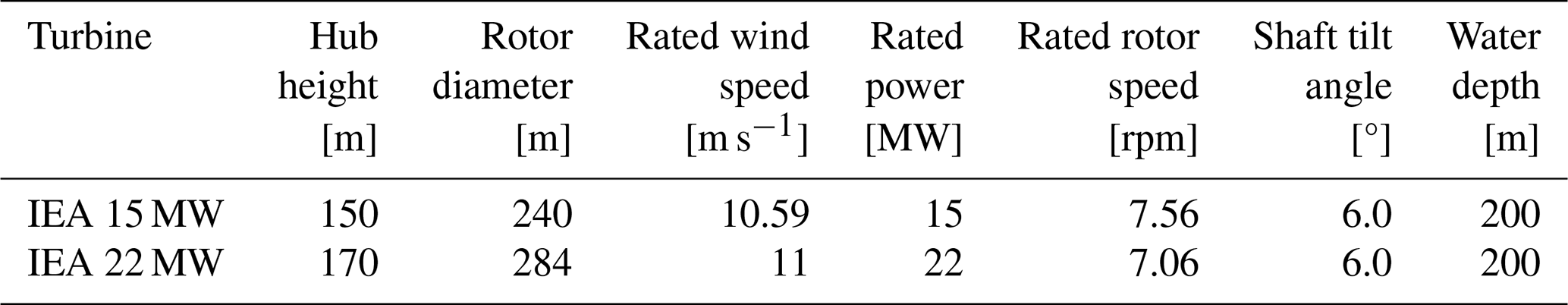
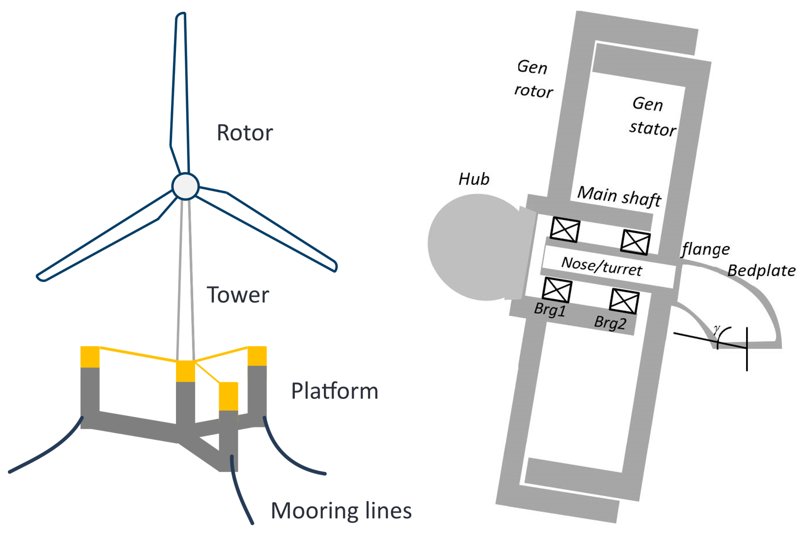
Figure 1The IEA 15 MW reference turbine (Krathe et al., 2025b) and its direct-drive generator (Gaertner et al., 2020). The IEA 22 MW turbine has a similar design.
The turbines were modeled in the aero-hydro-servo-elastic code OpenFAST (Jonkman et al., 2024). A ROSCO controller (Abbas et al., 2024) was applied for each turbine. Tower influence on wind speed was included using potential flow theory with the Bak correction (Bak et al., 2001). For such large rotors, it is generally recommended to account for large deflections in OpenFAST by modeling the blades using the geometrically exact beam theory in the module BeamDyn. Unfortunately, it was not computationally feasible to combine BeamDyn and the drivetrain model described in Sect. 3.1.2 for the floating turbines. Instead, ElastoDyn was applied, using a modal representation of the blades. A comparison between BeamDyn and ElastoDyn blades, using a traditional ElastoDyn tower and shaft (with combined modal and multibody representation), shows that while the specific values differ, the trends and magnitudes of veer effects with BeamDyn blades remain consistent with those presented in this paper.
3.1.2 Drivetrain model
In this work, the two reference OpenFAST models (Barter et al., 2024; Zahle et al., 2024b) were modified to include a flexible drivetrain, modeled together with the tower in the OpenFAST linear finite-element module SubDyn (NREL, 2024). This methodology allows for coupling of the structural dynamics of the rotor, tower and drivetrain. It was previously verified against a coupled multibody model and applied for a 10 MW geared drivetrain (Krathe et al., 2025a) and for the IEA 15 MW direct-drive turbine (Krathe et al., 2025b). In short, a flexible drivetrain was included in the aero-elastic analyses. Flexible beams were applied to represent the bedplate and shaft. Additional drivetrain mass and inertia were modeled using point masses. Main bearings were represented by constant stiffness springs. Bearing housing flexibility was not included. More details of this modeling approach can be found in the two aforementioned papers and on GitHub (Krathe, 2024). For comparison, OpenFAST models with rigid drivetrains and flexible towers were also built in SubDyn. Figure 2 presents the two versions of the aero-elastic model with flexible and rigid drivetrains. The bedplate and shaft's geometry and material properties of the flexible drivetrain were obtained directly from the WISDEM framework for each turbine (Barter et al., 2024; Zahle et al., 2024b).
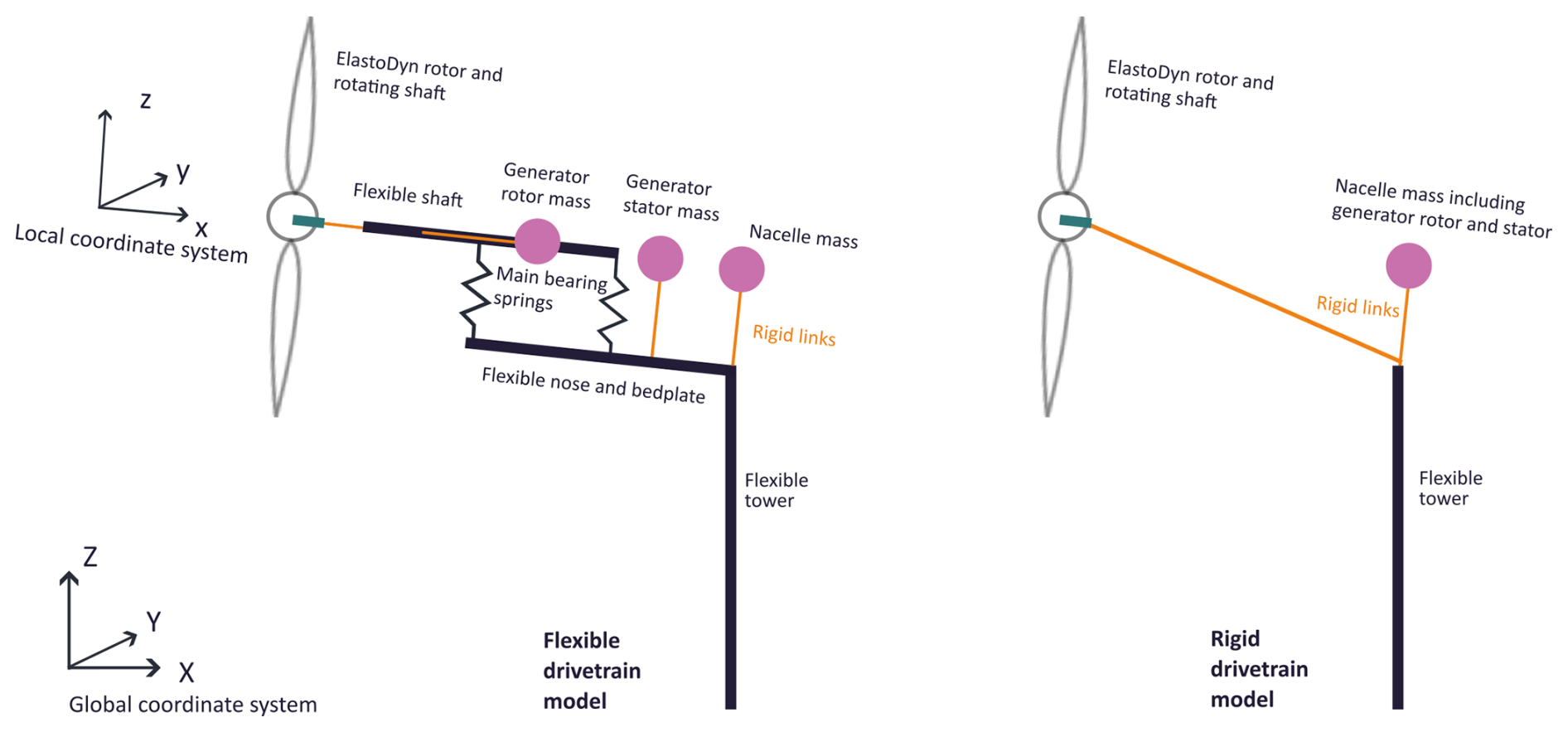
Figure 2Flexible and rigid drivetrain models in an aero-hydro-servo-elastic simulation framework. For simplicity, only main bearing springs in the local z-direction are illustrated. Local and global coordinate systems, applied for the main bearings and tower response, respectively, are also presented. From Krathe et al. (2025b) with modifications.
3.1.3 Main bearing representation in the drivetrain model
The main bearings were represented by 6 DOF constant springs, as follows. The force–displacement relationship (represented by F and u, respectively) in each spring was modeled by 6 × 6 stiffness matrices (K) as F=Ku. In K, for these specific bearings, any rotational stiffness was set to zero, and off-diagonal terms (discussed below) were included to represent coupling between axial loads and transverse loads. This is illustrated in Eq. (1), where x is in the axial direction (see for instance Chopra, 2020 and Nielsen (2024)).
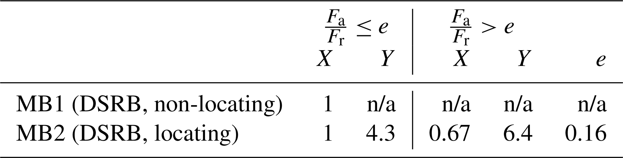
Based on discussions with industry and because TRBs require accounting for preload and undertaking advanced fatigue analyses beyond the scope of this work (Torsvik, 2020), two double-row spherical roller bearings (DSRBs) were considered: a downwind locating DSRB and an upwind non-locating DSRB (SKF, 2025). The upwind and downwind main bearings are referred to as MB1 and MB2, respectively. To the authors' knowledge, design details of main bearings suitable for turbines the size of 15 and 22 MW are not publicly available. In this work, the diagonals of the main bearing stiffness matrices were estimated using Schaeffler's tool (Schaeffler, 2025), which evaluates the load–deflection relationships of several smaller bearings for a number of different combinations of constant loads, extrapolating to the size of the 15 and 22 MW shaft.
DSRBs subjected to combined radial and axial loads have cross-coupling stiffness terms that are not easily estimated based on the aforementioned method. Royston and Basdogan (1998) found that these off-diagonal terms, kxy=kyx and kxz=kzx, were typically an order of magnitude smaller than the values of kxx and kyy, respectively. Therefore, the cross-coupling terms were crudely estimated as .
The estimated spring stiffnesses are summarized in Table 2. Note that there are large uncertainties in the main bearing stiffness estimates and that applying constant stiffnesses is in itself an approximation because main bearing stiffnesses are generally a function of load. Therefore, to understand how different main bearing stiffnesses influence the loads, upper, medium and lower stiffness estimates are presented (“high”, “medium” and “low”). The majority of the simulations were run with the “medium” stiffness, but in Sect. 4.1.3, the sensitivity of results to main bearing stiffness is discussed. This sensitivity test does not give conclusive answers regarding the effects of load-dependent stiffnesses, but it provides information regarding the uncertainty due to the applied constant stiffness, and (as will be discussed in Sect. 4.1.3) it indicates how much the main bearings contribute to drivetrain flexibility.
Table 2Main bearing spring stiffness in local coordinates. Low (L), medium (M) and high (H) values are shown as L/M/H. The “medium” values were applied in all simulations, except for the sensitivity study presented in Sect. 4.1.3.
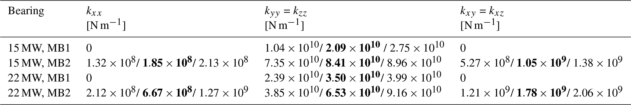
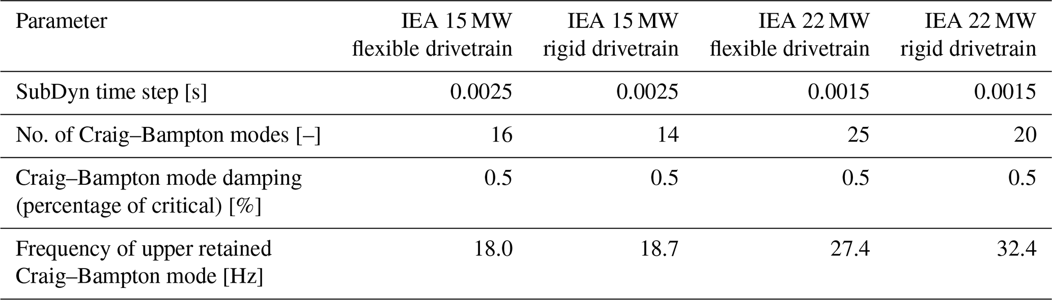
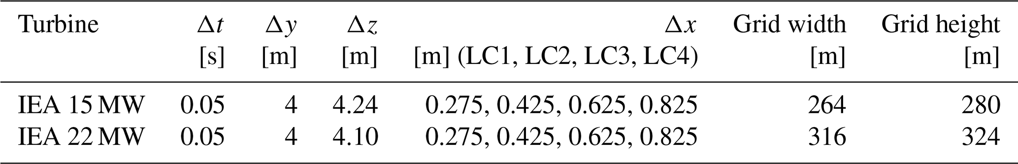
Table 3 documents the numerical setup in SubDyn for the different versions of the two turbine models. The IEA 22 MW turbine and IEA 15 MW turbine were run with a glue-code (OpenFAST) time step of 0.0015 and 0.0025 s, respectively. These were chosen to ensure numerical stability of the simulations and convergence of the Craig–Bampton model in SubDyn.
Table 3SubDyn numerical setup. The glue-code (OpenFAST) time steps were set similar to the SubDyn time steps.
3.2 Environmental load cases
3.2.1 Environmental data
NORA3 (Haakenstad et al., 2021; Haakenstad and Breivik, 2022) is a wind and wave hindcast dataset for northern Europe (Cheynet et al., 2024). It spans from 1982 to 2022, has a horizontal resolution of 3 km, a temporal resolution of 1 h and is a downscale of the ERA5 reanalysis (Hersbach et al., 2020). Based on NORA3, Cheynet et al. (2023, 2024) generated spatially averaged data for two Norwegian offshore wind turbine locations. In this work, 1 h median data for the deep-sea location Utsira Nord, designated for floating offshore wind farms, are applied to estimate environmental load conditions. Data are available at heights of 10, 20, 50, 100, 150, 250, 500 and 750 m.
The veer gradient was calculated using an expression for bulk veer (Murphy et al., 2020):
where θtop and θbottom are the mean wind direction at heights ztop=250 m and zbottom=10 m, respectively, to obtain wind directions representative of the rotor span. While the datasets yield different gradients for veer and backing, for comparability, the estimates for veer gradients were applied for the load cases with backing. Moreover, a constant gradient was assumed. Although several researchers have shown that the power law profile is not able to represent realistic wind profiles (Sathe et al., 2013; Lundquist, 2022; Murphy et al., 2020; Cheynet et al., 2024), in this work, the power law is applied for simplicity. It yields the mean wind speed as a function of height, , as follows:
The power law exponent, α, was found by fitting the power law using Scipy's non-linear least-squares fit (Virtanen et al., 2020), with data points up to 500 m. Although the two turbines in question have different hub heights, for simplicity, the reference mean wind speed is taken at the hub height of the IEA 15 MW turbine, that is, zhub=150 m and m.
3.2.2 Load cases
Four mean wind speeds at 150 m were selected: two below rated wind speed (5.5, 8.5 m s−1), one near rated (12.5 m s−1) and one above rated (16.5 m s−1). For each of the four mean wind speeds, the 99th percentile of β, given , was chosen. The power law exponent, α, was found as the mean value conditional on (±0.5 m s−1) and β (±0.3° m−1). Turbulence intensity at zhub was estimated based on the model by Andersen and Løvseth (2006) and described by Cheynet et al. (2024):
Although this formulation of turbulence intensity was developed for neutral conditions and moderate to strong wind speeds, it is assumed to be sufficient for the comparative nature of this study. Coherence was set in accordance with IEC standard 61400-1 Ed. 3 (IEC, 2005) (au=12.0 and ; av, aw→∞; bv, bw=0). The significant wave height, Hs, and peak period, Tp, were also estimated from the NORA3 dataset at Utsira Nord. Hs was taken as the 90th percentile conditional on and Tp as the mean value conditional on Hs. The Pierson–Moskowitz spectrum (Pierson and Moskowitz, 1964) was applied for the generation of long-crested irregular waves aligned with the mean wind direction.
The environmental load cases are summarized in Table 4, and the estimated wind directions are plotted in Fig. 3. Note that the turbulence intensity increases with wind speed, while the veer gradient decreases with wind speed. For each load case, a number of different wind fields were simulated to evaluate the influence of the different wind properties. These wind fields are summarized in Table 5.
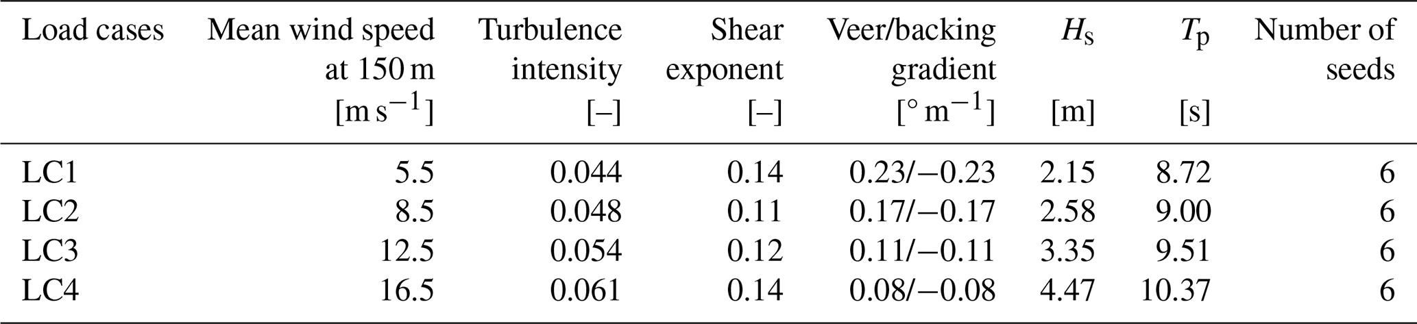
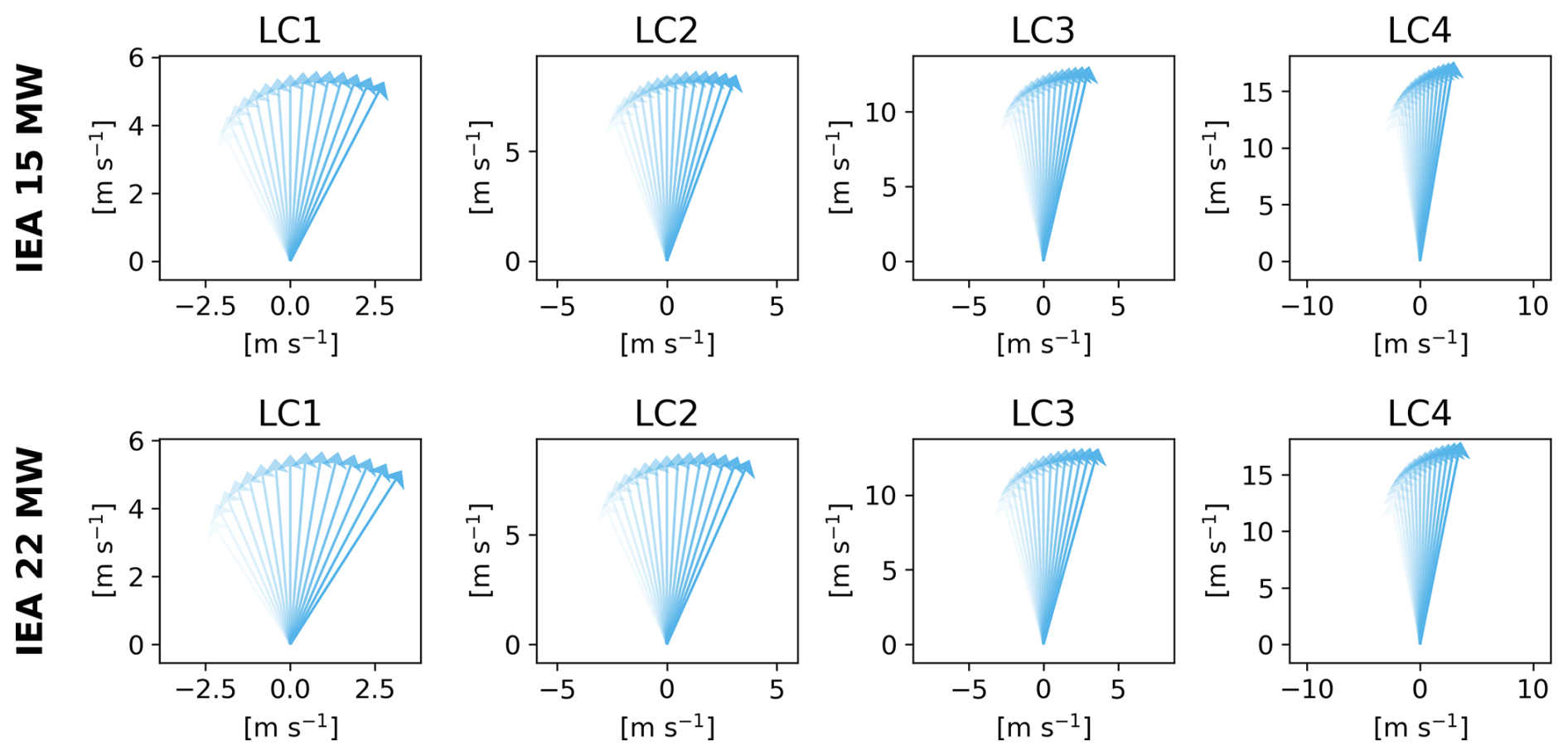
Figure 3Mean wind vector at different heights for each load case and turbine showing changes in wind direction (veer) and mean velocity (shear) with height. The color strength increases with height.
Table 5Wind fields including different properties. All conditions include waves.
The turbulent inflows were based on the Kaimal spectrum with the exponential coherence model (Kaimal et al., 1972) and generated using TurbSim (Jonkman, 2016). The TurbSim temporal and spatial resolution is presented in Table 6.
Simulations of 1 h were considered for each load case. To avoid transients, a total simulation length of 4600 s was applied, but only the final 3600 s were used in post-processing.
3.3 Damage equivalent loads
3.3.1 Tower and blade damage equivalent load
Short-term DELs were calculated for each time series according to Eq. (5) (Hayman, 2012) using Python scripts from the Wind Energy Library (Branlard, 2024, 2017). The load ranges, assuming zero mean and without the Goodman correction, , were found from rainflow counting. ni is the number of load cycles for each load range, neq is the total number of cycles in the time series and m is the Wöhler exponent.
The DEL has a constant amplitude and frequency, feq, in hertz, and produces the same short-term fatigue damage, D, as the variable loads (Hayman, 2012):
where T is the length of the time series in seconds, Neq is the equivalent number of load cycles until failure under the calculated DEL, and Ni and ni are the ith cycles to failure and number of load cycles for a time series, respectively. Here, an equivalent frequency, feq, of 1 Hz was applied. The load ranges were divided into 100 bins. The Wöhler exponent was taken as 10 for the blades (Jonkman and Matha, 2011) and 4 for the tower. The latter choice was a compromise based on an investigation of tower stress cycles from the analyses, showing stress cycles distributed on both sides of the transition point of the bi-linear S–N curve (m=3 and m=5, in accordance with DNV-RP-C203 (DNV, 2019)).
3.3.2 Main bearing damage equivalent loads
The bearing DEL formulation is different from that of the tower and blades. First, the dynamic equivalent radial load, P, is calculated:
Here, and Fa=Fx are the time series of the radial and axial bearing loads. The upwind, non-locating bearing was assumed to experience zero axial loads. Hence, for the upwind bearing, Fa=0 and P=Fr.
X and Y are radial and axial load factors, depending on the ratio between axial and radial loads, . X and Y were estimated based on product catalogs from two bearing manufacturers (Koyo, 2022; NSK, 2025), as described by Krathe et al. (2025b), and are listed in Table 7.
For each time step, i, the equivalent radial load, Pi, is calculated and combined with the shaft speed, ni, and the duration of each time step, ti, to form the short-term DELs of the roller bearings. Similarly as for the DELs of the blade and tower, this is a constant equivalent load that results in the same damage as a time-varying load (Budynas and Nisbett, 2011).
3.4 Modal analysis
Accurate estimation of full system natural frequencies is important to achieve a viable wind turbine design (Nielsen, 2024). Tower and rotor natural frequencies were found through modal analysis by linearizing the standstill turbine (generator locked) in OpenFAST (Jonkman et al., 2018) using the automated Campbell diagram code (ACDC) (Slaughter, 2024). The mooring lines were replaced by linear springs to facilitate the detection of modes in the modal analysis. Rigid-body-mode natural frequencies were found through decay tests. Aerodynamics were omitted and still water was considered for both methods. Such procedures are commonly applied to identify modes and natural frequencies of floating wind turbines (Browning et al., 2014; Robertson et al., 2014, 2017).
3.5 Load analysis
3.5.1 Main bearing loads
It is difficult to compare main bearing loads directly between the rigid and flexible drivetrain models, as the rigid drivetrain model does not output bearing loads. Analytical calculations could be applied, but they are complex to derive when bearings have coupling terms in their stiffness matrices. To address this limitation, shaft axial loads and shaft pitch and yaw moments are used as proxies for main bearing loads.
Because main bearing DELs are primarily driven by mean loads, shaft mean loads will be most important for this metric. However, given the uncertainty in using L10 lives to predict main bearing failure, load standard deviations are also reported to provide additional insight. The aim is to give a broader understanding of drivetrain flexibility and veer effects on main bearing loads.
Main bearing load statistics (mean and standard deviation) and their sensitivity to bearing stiffness are discussed in Sect. 4.1.3. The influence of veer on load standard deviations is presented in Sect. 4.2.3. Shaft loads as proxies for main bearing loads are applied when comparing response with rigid and flexible drivetrain models, detailed in Sect. 4.1.2.
3.5.2 Spectral analysis
The spectral analysis (Ochi, 1990; Naess and Moan, 2012) of loads enables the investigation of energy distribution across frequencies and facilitates the identification of the sources of response differences (Nybø et al., 2021). Response spectra were calculated by means of Welch's method with a Hamming window using six segments and 50 % overlap, averaged across seeds.
3.5.3 Isolated veer and backing effects
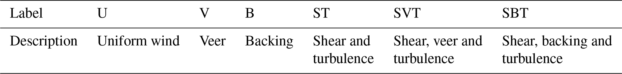
To understand the variations in loads with and without veer and backing, a simplified study similar to that of Wagner et al. (2010) was conducted for the 15 MW turbine. These simulations were run without waves and controller, with constant blade pitch and rotor speed, and with rigid blades. Tower shadow was included. The load cases with 8.5 and 16.5 m s−1 mean wind speed at hub height were considered (LC2 and LC4, respectively). In LC2, the average blade pitch was zero, and in LC4, the blade pitch was 13.5°. Wind fields without turbulence and shear were evaluated: “U” (uniform wind), “B” (backing, no shear or turbulence) and “V” (veer, no shear or turbulence). The results of this study are presented in Sect. 4.2.5.
4.1 Sensitivity to drivetrain flexibility
4.1.1 Modal analysis
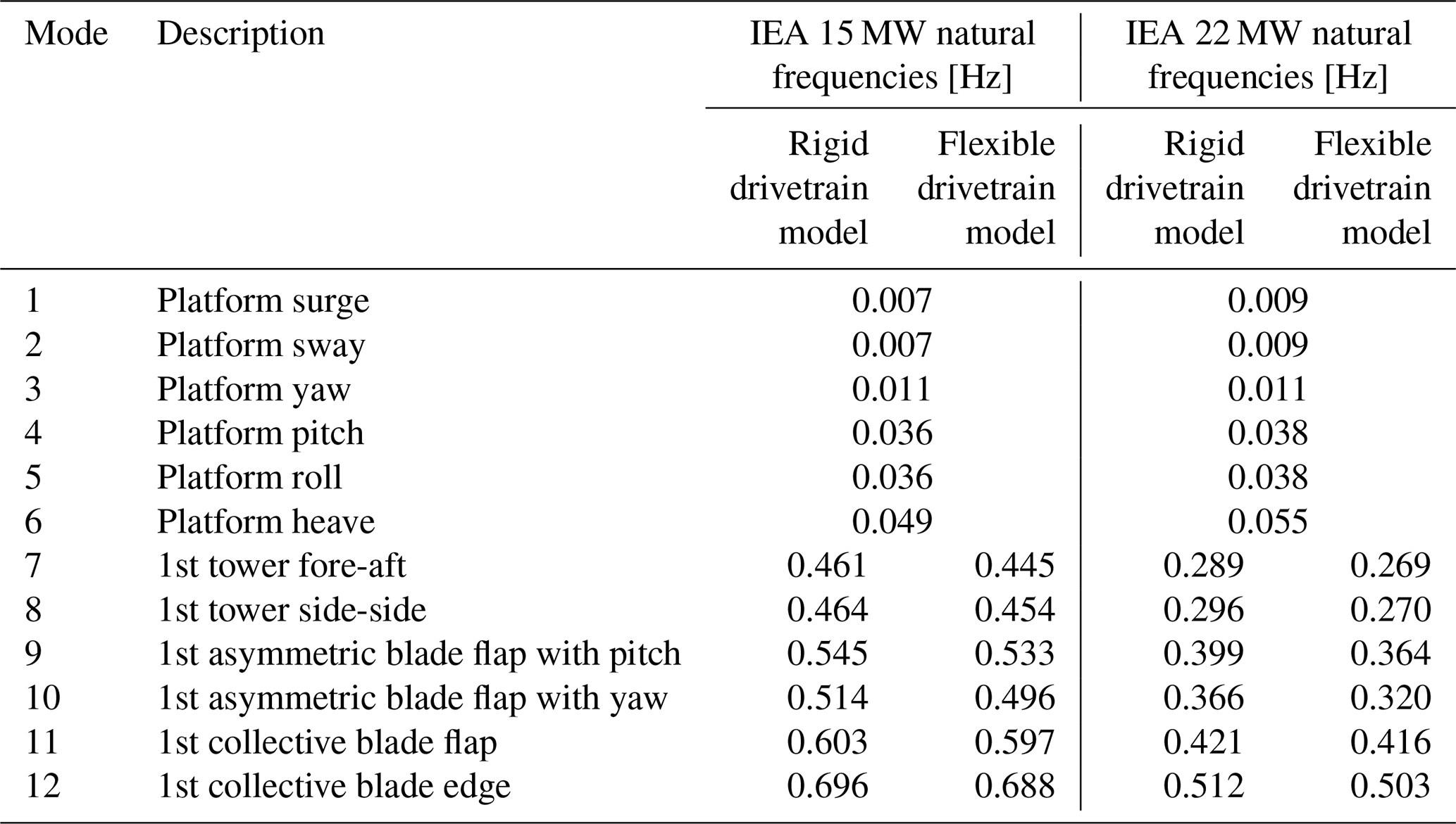
The results of the modal analyses are summarized in Table 8 for the two turbines with rigid and flexible drivetrains. For the IEA 15 MW turbine, the tower natural frequencies are reduced by 2.2 % and 3.5 % when including the flexible drivetrain. Similarly, the natural frequencies of the asymmetric blade flap mode with pitch and blade flap with yaw are reduced by 2.2 % and 3.5 %, respectively. Considering the IEA 22 MW turbine, the tower mode natural frequencies are reduced by 7 %–9 % with the flexible drivetrain, and the natural frequencies of the first asymmetric blade flap with pitch and yaw are reduced by 9 % and 12.5 %, respectively. Notably, for the 22 MW, the blade flap with yaw natural frequency (0.32 Hz) falls within the 3P (blade-passing frequency) regime (0.35 Hz at rated wind speed). It is, however, important to recognize that the rotational speed will influence the natural frequencies of the asymmetric rotor modes (typically, one will increase and one will decrease with rotational speed) (Holierhoek, 2022).
Table 8Damped natural frequencies (Hz) of the standstill floating IEA 15 and 22 MW turbines. The rigid body modes are the same across drivetrain models.
4.1.2 Comparison of loads and DELs of rigid and flexible drivetrains
A comparison of DELs extracted from simulations of the flexible and rigid drivetrain models is presented in Fig. 4 for each turbine. Only the SVT (shear, veer and turbulence) wind fields are considered. Six seeds were simulated for all cases. The differences are evaluated as follows:
Based on these simulations, it is clear that the flexibility of the drivetrain influences aero-elastic response, and the effect is significant for the 22 MW turbine tower-top moments. For the tower-top fore-aft bending moment (My) and the torsional moment (Mz), the flexible drivetrain reduces the DELs by up to 6.8 % for the 15 MW turbine. The same responses are reduced by up to 21.5 % for the 22 MW with a flexible drivetrain. The differences are greatest at near- and above-rated wind speed. Note that the tower-base and tower-top torsional moments are equal. The blade-root flapwise damage equivalent moments are less influenced when considering results averaged across seeds. They are reduced by a maximum of 1.6 % for the 15 MW turbine and by a maximum of 4.1 % for the 22 MW turbine. However, at 5.5 m s−1, the 22 MW turbine shows a large scatter in blade-root flapwise DELs.
For the tower-base fore-aft bending moment, the effect is generally small (below 3 % difference), except at 8.5 m s−1 for the 22 MW turbine, where the flexible drivetrain increases seed-averaged DELs by 7 %. The first tower natural frequencies of the IEA 22 MW turbine fall within the 3P region. At 8.5 m s−1, the tower natural frequency is close to the 3P frequency (0.26 Hz) and is shifted even closer when the flexible drivetrain is included. This could explain the increase in the tower-base fore-aft bending moment DEL with flexible drivetrain in LC2. Ideally, the tower should be designed so that its natural frequencies are outside of the 3P region, or the controller should be adjusted.
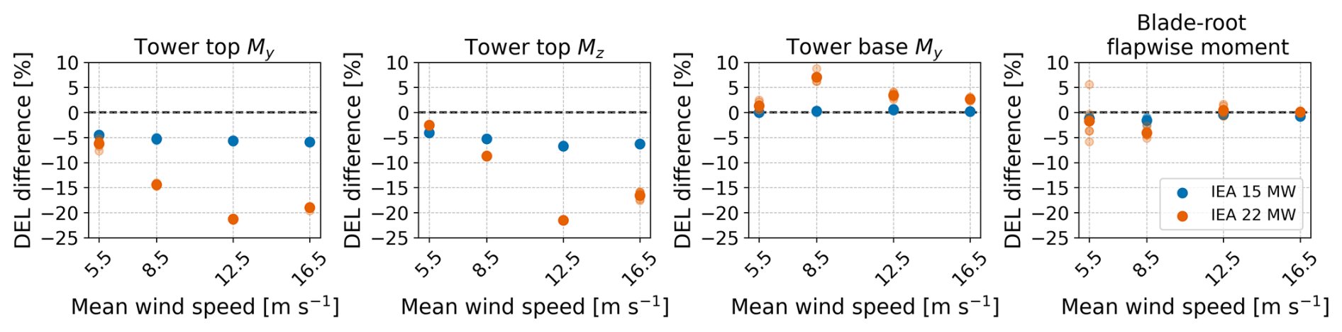
Figure 4Tower and blade damage equivalent moments of the flexible drivetrain model compared to the rigid drivetrain model for the IEA 15 MW and IEA 22 MW reference turbines. My and Mz are the fore-aft bending moment and the torsional moment, respectively. The plot presents individual results for each seed using transparent markers, while the average across six seeds is shown with full opacity.
As discussed in Sect. 3.5.1, shaft axial loads and bending moments are considered as proxies for main bearing loads for comparison between the rigid and flexible drivetrain model. Mean loads and standard deviations are compared in the same manner as the differences in DELs and presented in Fig. 5. Differences in shaft mean loads are negligible. Since main bearing DELs are primarily influenced by mean loads, this result suggests that drivetrain flexibility would have a low impact on them. Shaft axial load standard deviations increase, while the shaft bending moment standard deviations are reduced with the flexible drivetrain model. Again, the most significant impact of drivetrain flexibility is seen for the 22 MW turbine, whereas the 15 MW turbine is less affected. The greatest difference in axial load standard deviations is seen for the largest wind speed and for LC2 when considering the bending moment standard deviations.
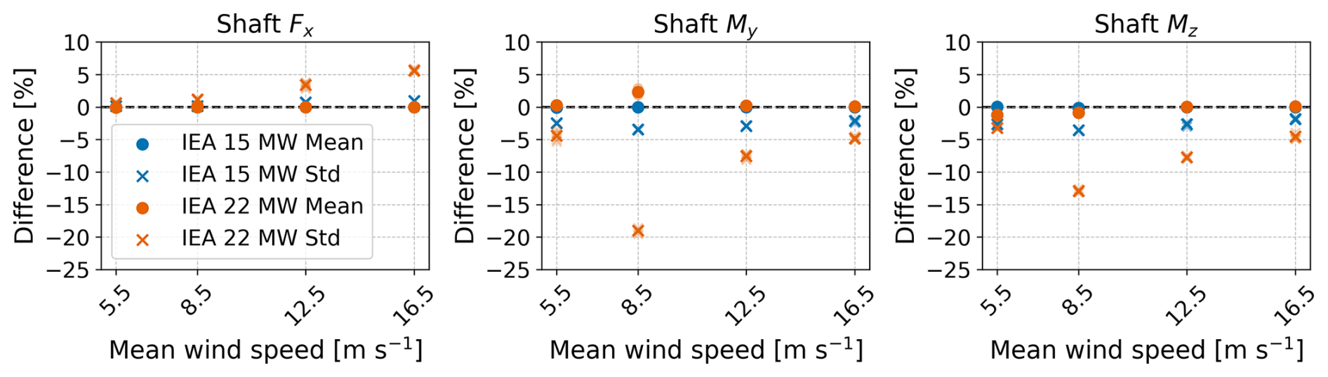
Figure 5Differences in shaft load means and standard deviations among the rigid and flexible drivetrain models. Fx, My and Mz denote the shaft axial force, pitch moment and yaw moment, respectively. The plot presents individual results for each seed using transparent markers, while the average across six seeds is shown with full opacity.
While drivetrain flexibility significantly influences the structural response, especially for the 22 MW turbine, it does not change the mean power output of the turbines. However, the standard deviations of the power outputs are increased by 1.7 %, averaged across seeds.
4.1.3 Load and DEL sensitivity to bearing stiffness
There are large uncertainties in the main bearing stiffness estimates. A test using six seeds of the SVT wind fields was conducted to evaluate effects of variations in bearing stiffness: in addition to the medium bearing stiffness, simulations were run with the low and high spring stiffness coefficients, presented in Table 2. The differences in the tower and blade-root DELs are presented in Fig. 6. The DEL differences are calculated as
for the drivetrain model with low main bearing stiffness and similarly for the model with high main bearing stiffness (replacing “Low” with “High”).
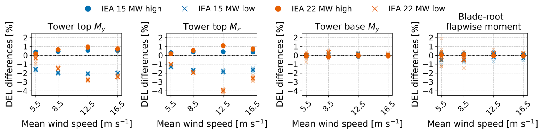
Figure 6Tower and blade damage equivalent moments for the IEA 15 MW and IEA 22 MW reference turbines with varying main bearing stiffness. My and Mz are the fore-aft bending moment and the torsional moment, respectively. The plot presents individual results for each seed using transparent markers, while the average across six seeds is shown with full opacity.
This span of variation in main bearing stiffness leads to less than 2 % difference in blade-root and less than 1 % difference in tower-base DELs.
With tower-top moments, larger differences are seen, especially with reduced bearing stiffness. Low main bearing stiffness reduces the damage equivalent fore-aft bending moment of the 15 MW turbine by up to 2 % and by up to 2.8 % for the 22 MW turbine. For the torsional moment DEL of the 15 MW turbine, less than 2 % reduction is seen with low bearing stiffness, whereas for the 22 MW turbine, the same DEL is reduced by 4 % for LC3. Higher main bearing stiffness leads to small increases in DELs of less than 1.2 %.
Main bearing DELs and mean loads (not plotted) are minimally affected, with a maximum difference of 0.3 %. Differences in downwind main bearing radial and axial load standard deviations (also not plotted) were calculated in the same manner as the differences in DELs. Reducing the bearing stiffnesses leads to a reduction in radial load standard deviations of 2 % and 1.8 % (averaged across seeds) for the 15 and the 22 MW turbine, respectively. Increasing the bearing stiffness is again less impactful, with a maximum increase in radial load standard deviations of about 0.5 %. Axial load standard deviations generally show low sensitivity to main bearing stiffness, with a maximum 1.2 % increase with reduced bearing stiffness for the 22 MW turbine at the highest mean wind speed. Similar results were seen for the upwind main bearing radial loads.
These results indicate that the responses evaluated do not change much with increased main bearing stiffness. As previously seen, the responses change more going from a rigid drivetrain to a flexible drivetrain. This may indicate that structural flexibility of the bedplate and shaft are more important when considering the effect of drivetrain flexibility than main bearing stiffnesses. Note again that main bearing stiffnesses are generally load dependent and that the assumption of constant spring stiffness is a simplification.
4.2 Response to different wind fields
Because veer and backing are not mentioned in design standards, it is interesting to evaluate the importance of veer compared to the typical design case with shear and turbulence. In this section, the influence of veer and backing on different load responses is investigated. Here, the results of the wind field SVT (shear, veer and turbulence) and SBT (shear, backing and turbulence) are compared to the ST (shear and turbulence) wind field. All conditions include waves.
4.2.1 Tower and blade DELs
DELs for the tower-top fore-aft bending moment and torsional moment, and the tower-base fore-aft bending moment are presented in Fig. 7 for wind fields ST, SVT and SBT. Compared to variations between wind fields, variations among seeds were generally small.
Considering tower-top DELs of the 22 MW turbine in below-rated wind speeds, veer leads to a doubling of the tower-top fore-aft DEL and an increase of more than three times the tower-top torsional DEL than without veer. In near-rated conditions (12.5 m s−1), SVT also leads to larger DELs than ST, but this changes in above-rated wind speed, where the ST wind fields lead to slightly higher DELs than the SVT wind fields.
The wind fields with backing generate significantly lower tower-top DELs compared to those with veer in below-rated wind speeds. This is seen for both turbines, and the differences are again especially significant for tower-top torsional moment. However, in LC1, adding backing leads to larger DELs for the 15 MW turbine but not for the 22 MW turbine. In LC4, SBT leads to larger tower-top moment DELs than ST (up to 10 % increase for torsional moment DELs).
The differences among the wind field conditions are small for the tower-base fore-aft bending moment DEL of the 15 MW turbine, while the tower base of the 22 MW experiences a 20 % increase in fore-aft damage equivalent bending moment in LC2 (8.5 m s−1) when veer is added.
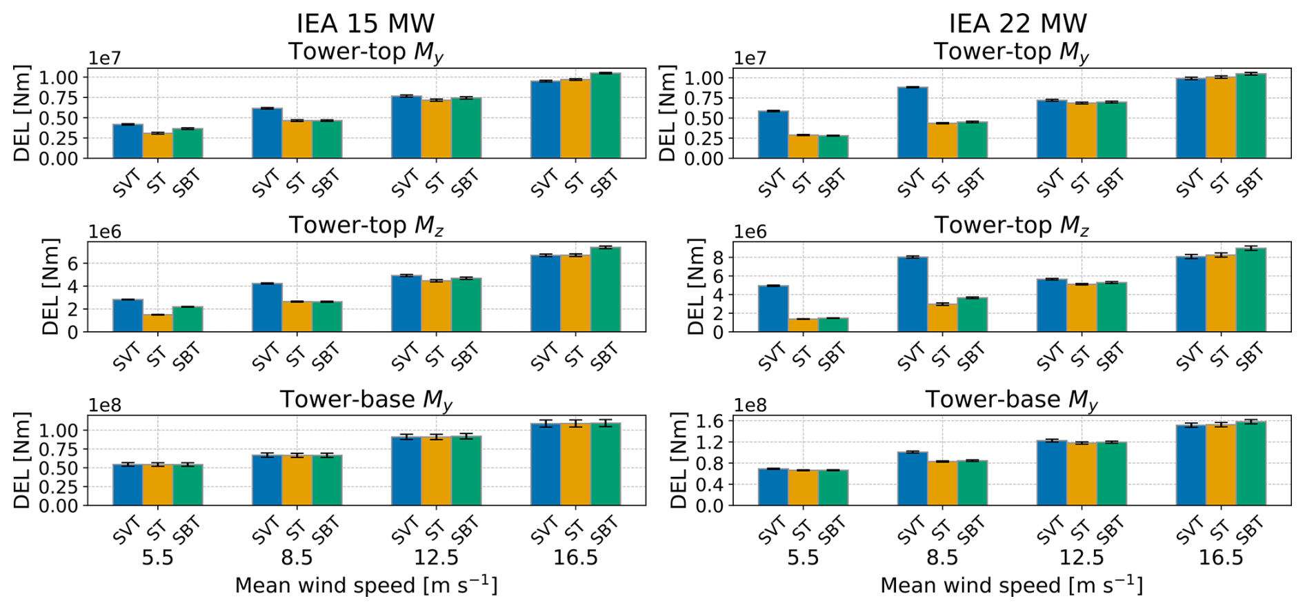
Figure 7Tower moment DELs for the wind fields ST, SVT and SBT from the flexible drivetrain model of the IEA 15 MW and IEA 22 MW reference turbines. The colored bars and the black error bars represent the mean values and standard deviations across the seeds of the turbulent wind fields, respectively. My and Mz are the fore-aft bending moment and the torsional moment, respectively.
Blade-root flapwise damage equivalent moments are plotted in Fig. 8. Here, veer and backing have less influence on the DELs (less than 6 % difference), except at 5.5 m s−1 for the 22 MW turbine, in which the inclusion of veer leads to a 15 % increase in flapwise DELs.
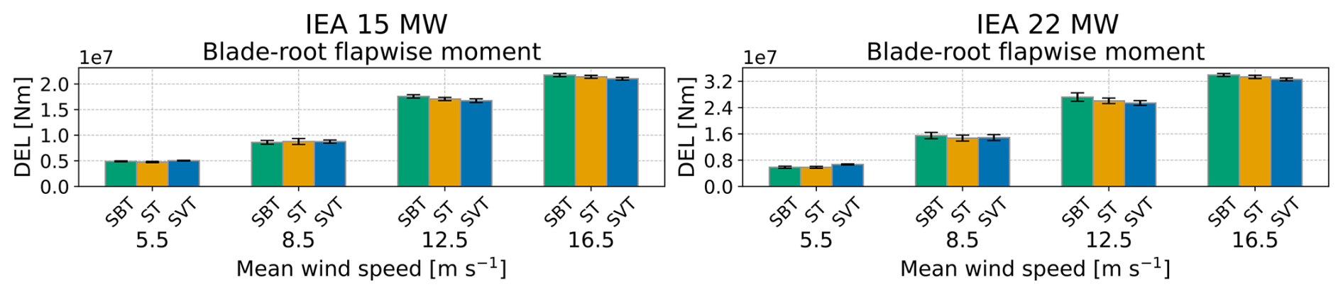
Figure 8Blade-root flapwise DELs for the wind fields ST, SVT and SBT for the flexible drivetrain model of the IEA 15 MW and IEA 22 MW turbines. The colored bars and the black error bars represent the mean values and standard deviations across the seeds of the turbulent wind fields, respectively.
4.2.2 Main bearing DELs
For main bearing DELs (not plotted), the differences between the turbulent wind fields are small for the 15 MW turbine – less than 2.5 %. With the inclusion of veer, an increase of up to 6 % is seen for the upwind main bearing of the 22 MW turbine at 8.5 m s−1 mean wind speed.
4.2.3 Main bearing radial load standard deviations
Main bearing radial load standard deviations are presented in Fig. 9. Main bearing radial loads are mainly governed by shaft pitch and yaw moment, and the results are similar to those presented for the tower-top DELs. Below rated wind speed, veer seems to be very important. This effect is reduced with higher wind speed (and reduced veer gradient) where turbulence prevails. Hart et al. (2022) found that the influence of veer on main bearing radial load fluctuations significantly increased with turbine size. Here, the same is evident in below-rated wind speeds, where veer generates a doubling of radial load standard deviations for the 22 MW turbine and a 40 % increase for the 15 MW turbine. Comparing backing and veer in below-rated conditions, they also align with those of Hart et al. (2022), who looked at veer at 10 m s−1 wind speed (for a wind turbine with 11.4 m s−1-rated wind speed) and found that veering wind led to higher main bearing radial load fluctuations than backing.
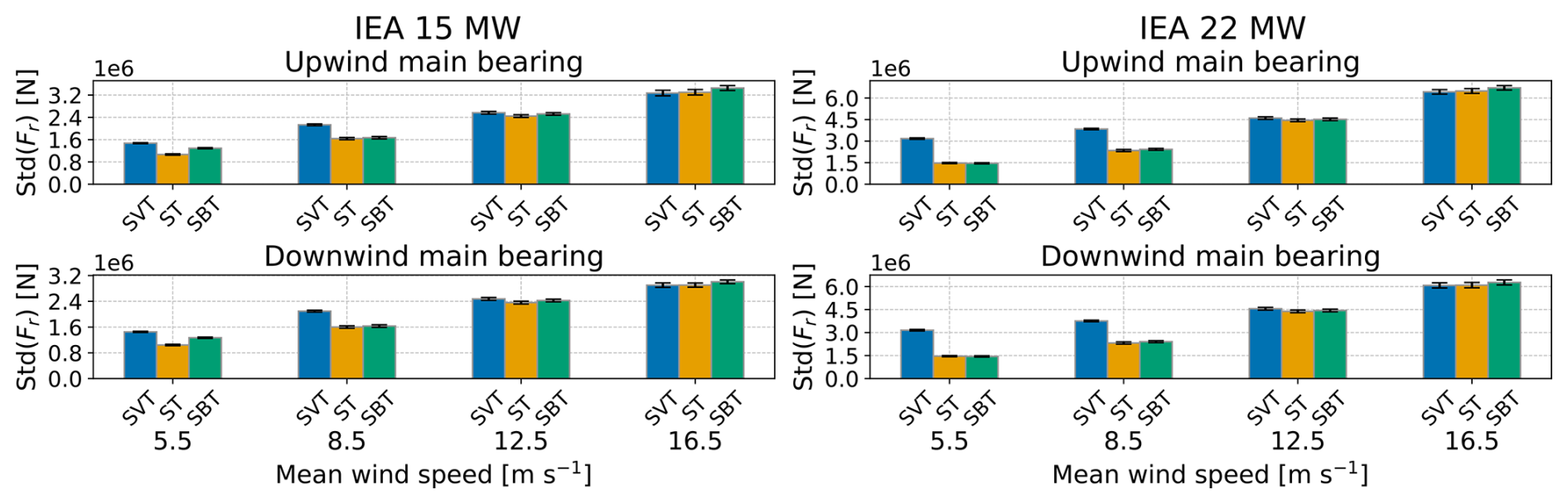
Figure 9Main bearing radial load standard deviations for the wind field ST, SVT and SBT for the flexible drivetrain model of the IEA 15 MW and IEA 22 MW turbines. The colored bars and the black error bars represent the mean values and standard deviations (of the standard deviations) across the seeds of the turbulent wind fields, respectively.
4.2.4 Response spectra
Power spectral densities of the tower-top fore-aft bending moment and blade-root flapwise moment are presented in Figs. 10–13 for wind fields ST, SBT and SVT. For both turbines, LC2 (8.5 m s−1) covers an operational area with a varying rotor speed. Hence, for this load case, the 3P peak is wider than for the other load cases.
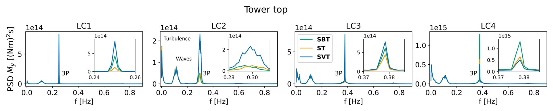
Figure 10Power spectral densities of the IEA 15 MW turbine tower-top fore-aft bending moment for the wind fields SBT, SVT and ST. The insets show the 3P frequency. Note the variations in the x axes of the insets. Note also the variations in the y axes among load cases.
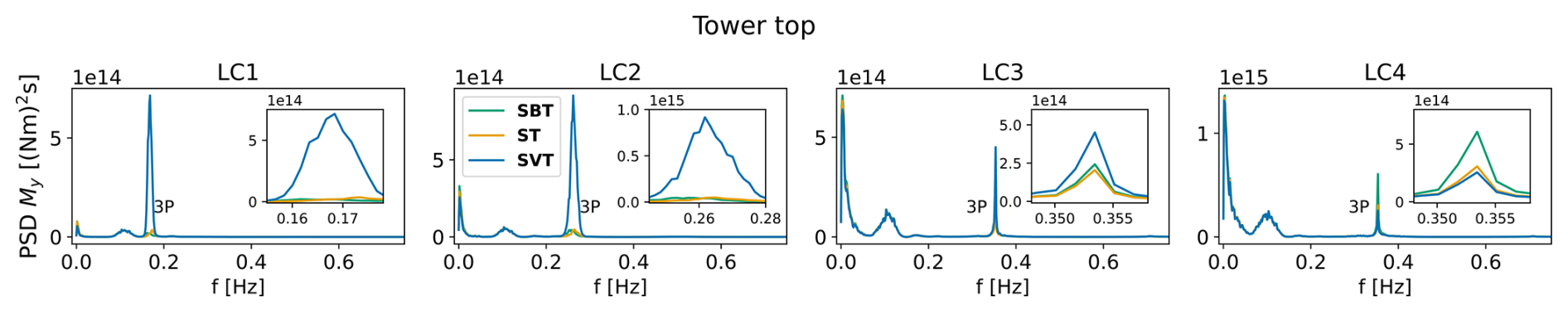
Figure 11Power spectral densities of the IEA 22 MW turbine tower-top fore-aft bending moment for the wind fields SBT, SVT and ST. The insets show the 3P frequency. Note the variations in the x axes of the insets. Note also the variations in the y axes among load cases.
For the tower-top fore-aft bending moment in below-rated conditions, the 3P peak is generally lower than the turbulence and wave excitation (far left and left of 3P, respectively) when veer is not present. However, the 3P response is significantly amplified by the addition of veer, leaving 3P the dominant source of excitation. For the wind field with backing, the peak is generally comparable to the wind field without directional shear (ST), except for LC1 and LC3 for the 15 MW turbine, where backing leads to a higher peak (but lower than SVT). The effect of veer is less significant for near-rated wind speed (LC3), and above rated the 3P peak is lower for SVT than for ST, and the SBT peak dominates. In above-rated conditions, the 3P peak is more significant (relative to turbulence and waves) for the 15 MW turbine than for the 22 MW turbine. Similar trends were found for the tower-top torsional moment and the main bearing radial loads.
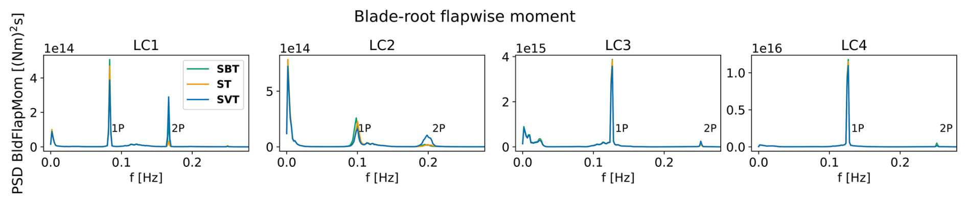
Figure 12Power spectral densities of the IEA 15 MW turbine blade-root flapwise moment for the wind fields. Note the variations in the y axes among load cases.
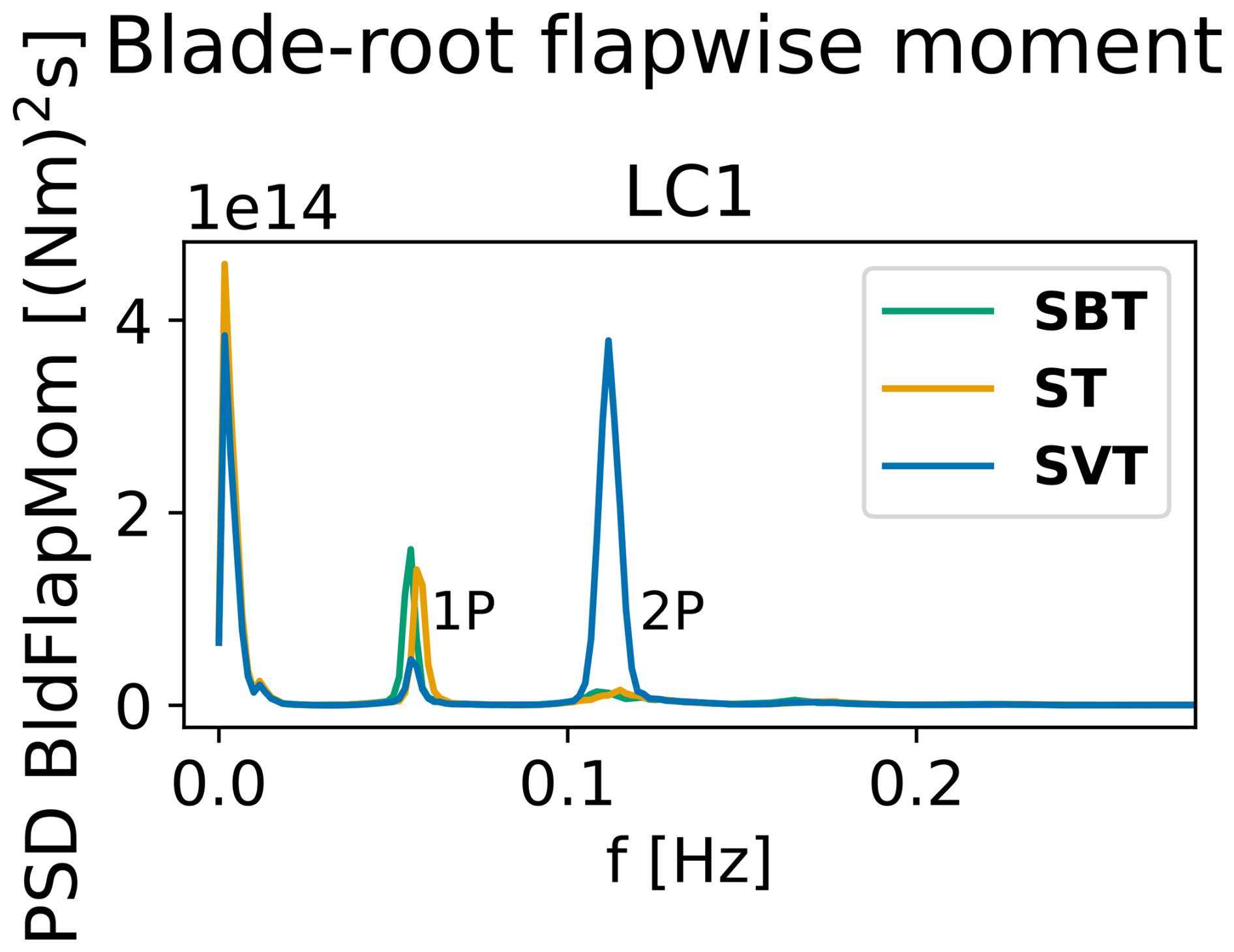
Figure 13Power spectral densities of the IEA 22 MW turbine blade-root flapwise moment for the wind fields SBT, SVT and ST for LC1. LC2–LC4 showed similar trends as the IEA 15 MW turbine.
With the blade-root flapwise moments, 1P dominates in above-rated conditions, with little difference between wind fields and turbines, although the peaks are slightly higher for SBT and ST than for SVT. Below-rated veer – along with backing in LC1 for the 15 MW turbine – introduces a pronounced 2P peak that is nearly negligible in the ST case. LC2 shows quite similar results for the two turbines: 2P is excited by the SVT wind field but not much by the ST and SBT wind fields, while 1P is more excited by ST and SBT than by SVT. This is also consistent with LC1. However, for LC1, the 22 MW turbine is governed by 2P (and the low-frequency turbulence), while the 15 MW turbine is dominated by 1P. The 1P excitation of the blade is well understood and driven by several characteristics of the turbulent wind field, including vertical shear, coherent eddies, tower shadow, and seemingly also wind directional shear. In contrast, the 2P excitation seems to be predominantly governed by directional shear, particularly veer. The increased significance of 2P for the 22 MW compared to the 15 MW may be attributed to its larger rotor diameter, which samples a broader range of wind directions. As a result, the 22 MW is more affected by veer – especially in LC1, which exhibits the strongest veer gradient among the load cases.
It is seen that veer introduces a significant 2P response in the blade-root bending moment in below-rated conditions. It is further seen that veer becomes the dominant source of excitation for the tower-top bending moment in below-rated conditions, while backing generates more energy in the above-rated conditions, with the contributions evident at 3P.
4.2.5 Azimuthal variation of load components
The results of the simplified study described in Sect. 3.5.3 are presented in Fig. 14. Generally, the main bearing radial load was governed by the main bearing vertical load, and the tower-top pitch moment followed the same trend as these two load components. The main bearing lateral load followed the same pattern as the tower-top yaw moment. Moreover, the two main bearings showed similar behavior. Therefore, only the radial load of the upwind main bearing and the tower-top yaw moment are plotted here.
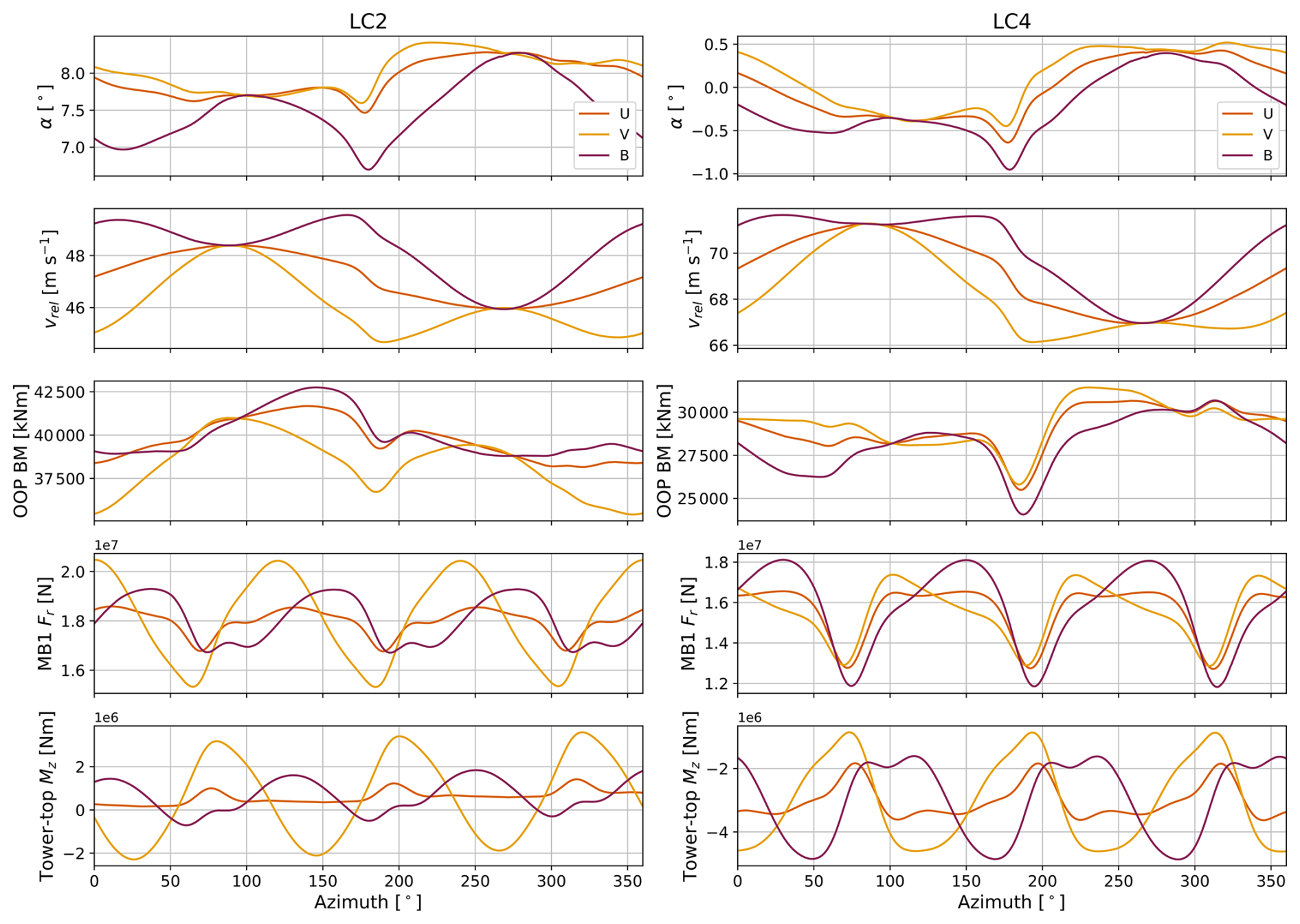
Figure 14The blade-root out-of-plane bending moment (OOP BM), main bearing radial load and tower-top yaw moment of the IEA 15 MW turbine plotted against rotor azimuth angle, together with the angle of attack (α) and relative wind velocity (vrel) that the blade sees at 75 % of its span. The blade is at its top position when the azimuth angle is 0/360° and passes the tower at 180°. Note that the blade pitch angle is 13.5° (toward feathered) for LC4 and 0° for LC2.
For LC2, the same effect that Wagner et al. (2010) described is seen: for backing, the angle of attack is smaller and the relative wind velocity is larger, while the opposite is true for veering wind. Angle of attack and relative wind speed seem to cancel each other in the backing case and amplify each other in the veering case, leading to smaller and larger amplitudes in the oscillations of the lift force, respectively. This further increases variations in the blade out-of-plane (OOP) bending moment in veer compared to backing. It is seen that veering wind leads to larger load variations than backing for both the main bearing radial loads and tower-top yaw moment. The 3P excitation is clearly seen for both cases, while there is a phase shift between backing and veering of 40 and 50° for the bearing radial loads and tower-top yaw moment, respectively. These observations can explain the difference in the 3P peak in the response spectra of the main bearing radial loads and tower-top bending moments when comparing backing and veer, and they can further explain the differences in tower DELs. The importance of 2P with veer can be explained by the two peaks in the OOP bending moment throughout one shaft rotation, at azimuth angles of about 80 and 250° in the yellow curve (“V”) in Fig. 14.
In LC4, differences in angle of attack between cases are not as pronounced, whereas differences in relative wind speed are quite similar to LC2. The large blade pitch angle of LC4 may reduce the importance of aerodynamic loads on the OOP bending moment relative to gravitational and inertia loads. The OOP bending moment is mostly lower for the backing case than the veering case, with a few exceptions around 127 and 313°. For the main bearing radial loads, the backing case exhibits larger load peaks and lower troughs compared to the veering condition, again with a 3P pattern. The tower-top yaw moment, on the other hand, experiences larger peak loads in veering conditions, but the duration of high loading is longer in the case of backing.
From this simplified study, it is seen that the effects of backing and veer depend on the blade pitch and mean wind speed, and that there is a phase shift and amplitude variation in 3P loading between the two conditions. The mechanism of the 2P loading in the blade-root OOP bending moment is also discussed.
In this work, two large floating reference wind turbines were considered. Each turbine was modeled in the coupled aero-hydro-servo-elastic simulation tool OpenFAST, including a flexible drivetrain model that incorporates drivetrain bending DOFs. These models were applied for two research purposes: first, the impact of drivetrain flexibility on aero-elastic response was assessed; second, the influence of wind directional change with height (veer and backing) on the turbine and main bearing DELs was investigated.
The results presented here are obtained within a set of limitations and premises. First, with rotor spans of 240 m and more, blade-bending and torsional flexibility become important. This could be more appropriately represented by the OpenFAST BeamDyn module compared to ElastoDyn. Issues related to computational efficiency prevented these simulations from being performed with BeamDyn. However, future work – aided by the upcoming upgrade to OpenFAST with tight coupling that will greatly speed up simulations with BeamDyn – should further investigate the interplay between blade flexibility and veer loading, and between blade flexibility and drivetrain flexibility. Second, there are large uncertainties with estimating main bearing stiffness coefficients of large main bearings, as these are not readily available from manufacturers. An attempt to account for this uncertainty was made by considering a span of main bearing stiffnesses. Load-dependent stiffness is not considered, and neither is the flexibility of the main bearing housing. DELs are applied to evaluate fatigue loading, but they do not capture all interactions between load components or multi-slope S-N curves and do not accurately predict fatigue life. Finally, regarding environmental conditions, a constant veer gradient throughout the rotor plane was considered, while non-linear variations of wind direction with height were also observed in the dataset. Similarly, a power law shear profile was assumed, although the dataset showed that some wind profiles associated with high veer were not well represented by the power law. Moreover, TurbSim was applied for generating synthetic turbulence. The choice of turbulence models and coherence is known to significantly influence the main bearing fatigue estimates (Krathe et al., 2025a), floater motions (Nybø et al., 2022) and tower-top loads (Nybø et al., 2021). Future studies should also combine veer and backing with other turbulence and coherence models. Finally, a similar analysis should be carried out for large floating wind turbines supported by other types of platforms. For example, spar-type wind turbines have less inertia and restoring in the yaw degree of freedom and may be more susceptible to wind veer.
The turbines with flexible drivetrains exhibit lower tower and rotor natural frequencies. The first tower natural frequencies are reduced by 2 %–3.5 % for the 15 MW turbine and by 7 %–9 % for the 22 MW turbine compared to models with rigid drivetrains. Similarly, natural frequencies of the asymmetric blade flap with pitch and blade flap with yaw modes (for a standstill turbine without aerodynamics) are reduced by 2 % and 3.5 % for the 15 MW turbine and by 9 % and 12.5 % for the 22 MW turbine. The asymmetric blade flap with yaw mode falls within the 3P regime of the 22 MW turbine, but this finding is for a standstill turbine, and frequencies may change with wind and rotor speeds and aerodynamic loads.
Including the flexible drivetrain in the aero-hydro-servo-elastic analysis leads to significant reductions in a tower-top torsional and fore-aft damage equivalent bending moment for the 22 MW turbine (21.5 %). Reductions are also seen for the 15 MW turbine (6.8 %). Blade-root flapwise damage equivalent moments are less influenced but show seed-averaged reductions of up to 4.1 % for the 22 MW turbine and 1.6 % for the 15 MW turbine. The tower-base fore-aft damage equivalent bending moment is generally little affected by the flexible drivetrain, except at 8.5 m s−1 where it leads to a 7 % increase in DEL for the 22 MW. This is likely because the floating tower natural frequency of the IEA 22 MW turbine falls within the 3P region (and more so with a flexible drivetrain), which is not an optimal design. Shaft mean loads see a negligible impact of drivetrain flexibility, indicating that the effect on main bearing DELs are small. However, shaft load standard deviations are affected (mainly for the 22 MW turbine), suggesting that incorporating drivetrain flexibility in the model may predict lower variation in main bearing radial loads, while main bearing axial load standard deviations will increase.
For the second objective, four sets of load cases were defined, two with mean wind speeds below-rated, one near-rated (slightly above) and one above-rated wind speed. Environmental data were estimated from NORA3 (Haakenstad et al., 2021; Cheynet et al., 2023, 2024) at Utsira Nord, a location intended for floating wind farms off the coast of Norway. For each load case, a set of six wind fields were defined: (1) uniform constant wind, (2) wind with a veer profile, (3) wind with a backing profile, (4) wind with shear and turbulence, (5) wind with shear, veer and turbulence, and (6) wind with shear, backing and turbulence. The last three wind fields were combined with waves. Coupled aero-elastic simulations were run for each turbine and each wind field in each load case. DELs of the tower fore-aft bending moment and torsional moment, blade-root flapwise moment and main bearings were investigated.
When comparing turbulent wind fields with and without veer and backing, it is clear that veer becomes very important in some load cases. For the lowest wind speed (and highest veer gradient), the tower-top DELs are underestimated by 50 % (fore-aft bending moment) and 72 % (torsional moment) for the 22 MW turbine when omitting veer. For the 15 MW turbine, the corresponding underestimations are 25 % and 47 %. Backing also leads to increased tower-top DELs for the 15 MW at the lowest wind speed (5.5 m s−1, 16 % for the fore-aft bending moment, 32 % for the torsional moment) but has a low effect on the DELs of the 22 MW turbine in the same load case. With increasing wind speed (and lower veer gradient and increasing turbulence intensity), veer becomes less important. Similar trends are found for the main bearing radial load standard deviations, while main bearing DELs exhibit little impact of veer and backing. Blade-root damage equivalent moments are also less affected, with an exception of a 15 % increase in DELs at 5.5 m s−1 mean wind speed for the 22 MW turbine when including veer.
Looking at the response spectra, 3P (not surprisingly) is identified as the major driver of the differences in tower DELs, while 1P and 2P frequencies govern the blade-root flapwise DELs. A significant 2P peak occurs for the wind fields including veer compared to those with backing in below-rated wind speeds. The combination of changes in relative velocity and angle of attack are thought to cause these differences between backing and veer.
To summarize, veer can be of very high importance to tower-top DELs, depending on turbine size, veer gradient and operating regime. Moreover, including drivetrain flexibility in aero-elastic analyses significantly reduces the tower-top DELs, especially for the largest turbine. Main bearing DELs saw little effect from both veer and drivetrain flexibility. Assuming fatigue according to ISO 281 is able to predict main bearing failure rates, veer does not seem to be the source of premature wind turbine main bearing failure. Recommendations for future work include investigating the influence of low-level jets and other shear profiles on the main bearing and tower-top response, preferably together with wind directional shear (veer and backing), and investigating the effects of combining higher fidelity blade models with flexible drivetrains in aero-elastic analyses.
Data are available from the authors upon request.
VLK built the coupled turbine models, analyzed NORA3 data to assemble the load cases, performed the analyses and the post-processing, wrote the paper, and did the editing of the draft and the final version. JJ and EEBP provided supervision, validated the results, and reviewed and edited the paper.
At least one of the (co-)authors is a member of the editorial board of Wind Energy Science. The peer-review process was guided by an independent editor, and the authors also have no other competing interests to declare.
The views expressed in the article do not necessarily represent the views of the DOE or the U.S. Government.
Publisher's note: Copernicus Publications remains neutral with regard to jurisdictional claims made in the text, published maps, institutional affiliations, or any other geographical representation in this paper. While Copernicus Publications makes every effort to include appropriate place names, the final responsibility lies with the authors. Views expressed in the text are those of the authors and do not necessarily reflect the views of the publisher.
The authors would like to acknowledge Rebeca Marini at VUB and Etienne Cheynet at UiB for fruitful discussions. This work is partly funded by the FME NorthWind project (grant no. 321954), funded by the Norwegian Research Council. This work was authored in part by the National Renewable Energy Laboratory for the U.S. Department of Energy (DOE) under contract no. DE-AC36-08GO28308. Funding provided by the U.S. Department of Energy Office of Energy Efficiency and Renewable Energy Wind Energy Technologies Office.
This work is partly funded by the FME NorthWind project (grant 321954), which is funded by the Norwegian Research Council. This work was authored in part by the National Renewable Energy Laboratory of the US Department of Energy (DOE) under contract no. DE-AC36-08GO28308. Funding was also provided by the US Department of Energy Office of Energy Efficiency and Renewable Energy Wind Energy Technologies Office.
This paper was edited by Jonathan Whale and reviewed by two anonymous referees.
Abbas, N. J., Zalkind, D., Mudafort, R. M., Hylander, G., Mulders, S., Heffernan, D., and Bortolotti, P.: NREL/ROSCO: ROSCO v2.9.0, Zenodo [code], https://doi.org/10.5281/zenodo.10535404, 2024. a
Allen, C., Viselli, A., Dagher, H., Goupee, A. J., Gaertner, E., Abbas, N., Hall, M., Barter, G., and Wind, I. E. A.: Definition of the UMaine VolturnUS-S Reference Platform Developed for the IEA Wind 15- Megawatt Offshore Reference Wind Turbine, Tech. rep., NREL, https://docs.nrel.gov/docs/fy20osti/76773.pdf (last access: 1 December 2025), 2020. a
Andersen, O. J. and Løvseth, J.: The Frøya database and maritime boundary layer wind description, Marine Structures, 19, 173–192, https://doi.org/10.1016/j.marstruc.2006.07.003, 2006. a
Bak, C., Aagaard Madsen, H., and Johansen, J.: Influence from blade-tower interaction on fatigue loads and dynamics (poster), https://orbit.dtu.dk/en/publications/influence-from-blade-tower-interaction-on-fatigue-loads-and-dynam/ (last access: 1 December 2025), 2001. a
Barter, G., Bortolotti, P., Gaertner, E., Rinker, J., Abbas, N. J., dzalkind, Zahle, F., T-Wainwright, Branlard, E., Wang, L., Padrón, L. A., Hall, M., and lssraman: IEAWindTask37/IEA-15-240-RWT, Zenodo [data set and code], https://doi.org/10.5281/zenodo.10664562, 2024. a, b
Bodini, N., Lundquist, J. K., and Kirincich, A.: U.S. East Coast Lidar Measurements Show Offshore Wind Turbines Will Encounter Very Low Atmospheric Turbulence, Geophysical Research Letters, 46, 5582–5591, https://doi.org/10.1029/2019GL082636, 2019. a
Bodini, N., Lundquist, J. K., and Kirincich, A.: Offshore Wind Turbines Will Encounter Very Low Atmospheric Turbulence, Journal of Physics: Conference Series, 1452, https://doi.org/10.1088/1742-6596/1452/1/012023, 2020. a
Boopathi, K., Mishnaevsky Jr., L., Sumantraa, B., Premkumar, S. A., Thamodharan, K., and Balaraman, K.: Failure mechanisms of wind turbine blades in India: Climatic, regional, and seasonal variability, Wind Energy, 25, 968–979, https://doi.org/10.1002/we.2706, 2022. a
Branlard, E.: Wind Turbine Aerodynamics and Vorticity-Based Methods: Fundamentals and Recent Applications, Springer International Publishing, ISBN 978-3-319-55163-0, https://doi.org/10.1007/978-3-319-55164-7, 2017. a
Branlard, E.: welib: A Python Library for Wind Energy Applications, https://github.com/ebranlard/welib (last access: 1 December 2025), 2024. a
Broadbent, Z.: Improving Bearing Life in Wind Turbine Mainshafts and Gearboxes, Tech. rep., Timken, https://www.timken.com/resources/improving-bearing-life-in-wind-turbine-main-shafts-and-gearboxes/ (last access: 1 December 2025), 2023. a, b
Browning, J. R., Jonkman, J., Robertson, A., and Goupee, A. J.: Calibration and validation of a spar-type floating offshore wind turbine model using the FAST dynamic simulation tool, Journal of Physics: Conference Series, 555, https://doi.org/10.1088/1742-6596/555/1/012015, 2014. a
Budynas, R. G. and Nisbett, J. K.: Shigley's mechanical engineering design, McGraw-Hill, ISBN 0073529281, 2011. a, b
Burton, T., Jenkins, N., Sharpe, D., and Bossyani, E.: Wind Energy Handbook, third edn., Wiley, ISBN 9781119451099, 2021. a
Cheynet, E., Li, L., and Jiang, Z.: Spatially averaged metocean data at Utsira Nord (UN) and Sørlige Nordsjø II (SN2) with NORA3 (1982–2022), Zenodo [data set], https://doi.org/10.5281/zenodo.10048159, 2023. a, b, c
Cheynet, E., Li, L., and Jiang, Z.: Metocean conditions at two Norwegian sites for development of offshore wind farms, Renewable Energy, 224, 120184, https://doi.org/10.1016/j.renene.2024.120184, 2024. a, b, c, d, e, f
Chopra, A. K.: Dynamics of Structures. Theory and Applications to Earthquake Engineering, Pearson Education Limited, fifth edn., University of California at Berkeley, ISBN 978-0-13-285803-8, 2020. a
Chou, J.-S. and Tu, W.-T.: Failure analysis and risk management of a collapsed large wind turbine tower, Engineering Failure Analysis, 18, 295–313, https://doi.org/10.1016/j.engfailanal.2010.09.008, 2011. a
DNV: DNV-RP-C203 Fatigue design of offshore steel structures, https://www.dnv.com/energy/standards-guidelines/dnv-rp-c203-fatigue-design-of-offshore-steel-structures/ (last access: 1 December 2025), 2019. a, b
DNV: Bladed Engineering Feature Summary, Tech. rep., DNV, https://www.dnv.com/software/services/bladed-turbine-design/ (last access: 1 December 2025), 2025a. a
DNV: Bladed – wind turbine design software, https://www.dnv.com/software/services/bladed/ (last access: 1 December 2025), 2025b. a
DTU: HAWC2, https://www.hawc2.dk/ (last access: 1 December 2025), 2025. a
Gaertner, E., Rinker, J., Sethuraman, L., Zahle, F., Anderson, B., Barter, G., Abbas, N., Meng, F., Bortolotti, P., Skrzypiński, W., Scott, G., Feil, R., Bredmose, H., Dykes, K., Shields, M., Allen, C., Viselli, A., and Wind, I. E. A.: Definition of the IEA Wind 15-Megawatt Offshore Reference Wind Turbine, Tech. Rep. NREL/TP-5000-75698, NREL, https://docs.nrel.gov/docs/fy20osti/75698.pdf (last access: 1 December 2025), 2020. a, b
Guo, Y., Parsons, T., King, R., Dykes, K., and Veers, P.: An Analytical Formulation for Sizing and Estimating the Dimensions and Weight of Wind Turbine Hub and Drivetrain Components, Tech. rep., NREL, Boulder, CO, https://www.nrel.gov/docs/fy15osti/63008.pdf (last access: 1 December 2025), 2015. a
Haakenstad, H. and Breivik, Ø.: NORA3. Part II: Precipitation and Temperature Statistics in Complex Terrain Modeled with a Nonhydrostatic Model, Journal of Applied Meteorology and Climatology, 61, 1549–1572, https://doi.org/10.1175/JAMC-D-22-0005.1, 2022. a
Haakenstad, H., Breivik, Ø., Furevik, B. R., Reistad, M., Bohlinger, P., and Aarnes, O. J.: NORA3: A Nonhydrostatic High-Resolution Hindcast of the North Sea, the Norwegian Sea, and the Barents Sea, Journal of Applied Meteorology and Climatology, 60, 1443–1464, https://doi.org/10.1175/JAMC-D-21-0029.1, 2021. a, b, c
Hart, E., Turnbull, A., Feuchtwang, J., McMillan, D., Golysheva, E., and Elliott, R.: Wind turbine main‐bearing loading and wind field characteristics, Wind Energy, 22, https://doi.org/10.1002/we.2386, 2019. a
Hart, E., Clarke, B., Nicholas, G., Kazemi Amiri, A., Stirling, J., Carroll, J., Dwyer-Joyce, R., McDonald, A., and Long, H.: A review of wind turbine main bearings: design, operation, modelling, damage mechanisms and fault detection, Wind Energ. Sci., 5, 105–124, https://doi.org/10.5194/wes-5-105-2020, 2020. a
Hart, E., Stock, A., Elderfield, G., Elliott, R., Brasseur, J., Keller, J., Guo, Y., and Song, W.: Impacts of wind field characteristics and non-steady deterministic wind events on time-varying main-bearing loads, Wind Energ. Sci., 7, 1209–1226, https://doi.org/10.5194/wes-7-1209-2022, 2022. a, b, c, d, e
Hart, E., Raby, K., Keller, J., Sheng, S., Long, H., Carroll, J., Brasseur, J., and Tough, F.: Main Bearing Replacement and Damage – A Field Data Study on 15 Gigawatts of Wind Energy Capacity, Tech. rep., National Renewable Energy Laboratory, Golden, CO, https://www.nrel.gov/docs/fy23osti/86228.pdf (last access: 1 December 2025), 2023. a, b
Hayman, G. J.: MLife Theory Manual for Version 1.00, Tech. rep., NREL, https://www.nrel.gov/docs/libraries/wind-docs/mlife-theory.pdf (last access: 1 December 2025), 2012. a, b
Hersbach, H., Bell, B., Berrisford, P., Hirahara, S., Horányi, A., Muñoz-Sabater, J., Nicolas, J., Peubey, C., Radu, R., Schepers, D., Simmons, A., Soci, C., Abdalla, S., Abellan, X., Balsamo, G., Bechtold, P., Biavati, G., Bidlot, J., Bonavita, M., De Chiara, G., Dahlgren, P., Dee, D., Diamantakis, M., Dragani, R., Flemming, J., Forbes, R., Fuentes, M., Geer, A., Haimberger, L., Healy, S., Hogan, R. J., Hólm, E., Janisková, M., Keeley, S., Laloyaux, P., Lopez, P., Lupu, C., Radnoti, G., de Rosnay, P., Rozum, I., Vamborg, F., Villaume, S., and Thépaut, J. N.: The ERA5 global reanalysis, Quarterly Journal of the Royal Meteorological Society, 146, 1999–2049, https://doi.org/10.1002/qj.3803, 2020. a
Holierhoek, J. G.: Aeroelastic Stability Models, in: Handbook of Wind Energy Aerodynamics, edited by: Stoevesandt, B., Schepers, G., Fuglsang, P., and Sun, Y., chap. 16, Springer, ISBN 978-3-030-31306-7, 2022. a
IEC: NEK IEC 61400-1:2005 Wind energy generation systems – Part 1: Design requirements, edn. 3, https://online.standard.no/nb/iec-61400-1-2005-ed3 (last access: 1 December 2025), 2005. a
IEC: NEK IEC 61400-1:2019 Wind energy generation systems – Part 1: Design requirements, edn. 4, https://online.standard.no/nb/iec-61400-1-2019-ed4 (last access: 1 December 2025), 2019. a, b
International Organization for Standardization: ISO 281:2007 Rolling bearings-Dynamic load ratings and rating life, https://online.standard.no/nb/iso-281-2007-2 (last access: 1 December 2025), 2007. a
IRENA: Future of Wind: Deployment, Investment, Technology, Grid Integration and Socio-Economic Aspects (A Global Energy Transformation paper), Tech. rep., IRENA, Abu Dhabi, https://www.irena.org/-/media/Files/IRENA/Agency/Publication/2019/Oct/IRENA_Future_of_wind_2019.pdf (last access: 1 December 2025), 2019. a
Jonkman, B., Platt, A., Mudafort, R. M., Branlard, E., Sprague, M., Ross, H., jjonkman, HaymanConsulting, Slaughter, D., Hall, M., Vijayakumar, G., Buhl, M., Russell9798, Bortolotti, P., reos-rcrozier, Ananthan, S., RyanDavies19, S., M., Rood, J., rdamiani, nrmendoza, sinolonghai, pschuenemann, ashesh2512, kshaler, Housner, S., psakievich, Wang, L., Bendl, K., and Carmo, L.: OpenFAST/openfast: v3.5.3, Zenodo [code and software], https://doi.org/10.5281/zenodo.10962897, 2024. a, b
Jonkman, B. J.: TurbSim User’s Guide v2.00.00, Tech. rep., National Renewable Energy Laboratory, https://www.nrel.gov/docs/libraries/wind-docs/turbsim_v2-00-pdf.pdf?sfvrsn=5a0a30f8_1 (last access: 1 December 2025), 2016. a
Jonkman, J. M. and Matha, D.: Dynamics of offshore floating wind turbines – analysis of three concepts, Wind Energy, 14, 557–569, https://doi.org/10.1002/we.442, 2011. a
Jonkman, J. M., Wright, A. D., Hayman, G. J., and Robertson, A. N.: Full-system linearization for floating offshore wind turbines in OpenFAST, in: ASME 2018 1st International Offshore Wind Technical Conference, p. V001T01A028, International Conference on Offshore Mechanics and Arctic Engineering, San Francisco, https://doi.org/10.1115/IOWTC2018-1025, 2018. a
Kaimal, J. C., Wyngaard, J. C., Izumi, Y., and Coté, O. R.: Spectral characteristics of surface-layer turbulence, Quarterly Journal of the Royal Meteorological Society, 98, 563–589, https://doi.org/10.1002/qj.49709841707, 1972. a
Kenworthy, J., Hart, E., Stirling, J., Stock, A., Keller, J., Guo, Y., Brasseur, J., and Evans, R.: Wind turbine main bearing rating lives as determined by IEC 61400-1 and ISO 281: A critical review and exploratory case study, Wind Energy, 27, 179–197, https://doi.org/10.1002/we.2883, 2024. a, b, c
Koyo: Large size ball & roller bearings. General bearings, https://koyo.jtekt.co.jp/en/support/catalog-download/uploads/catbs008en.pdf (last access: 1 December 2025), 2022. a
Krathe, V. L.: SubDrive: OpenFAST-drivetrain-modeling, Github [code], https://github.com/verlivkra/SubDrive (last access: 1 December 2025), 2024. a, b
Krathe, V. L., Jonkman, J., Gebel, J., Rivera-Arreba, I., Nejad, A., and Bachynski-Polić, E.: Investigation of Main Bearing Fatigue Estimate Sensitivity to Synthetic Turbulence Models Using a Novel Drivetrain Model Implemented in OpenFAST, Wind Energy, 28, e70005, https://doi.org/10.1002/we.70005, 2025a. a, b, c, d, e, f
Krathe, V. L., Thedin, R., Jonkman, J., Nejad, A. R., and Bachynski-Polić, E. E.: Main bearing response in a waked 15-MW floating wind turbine in below-rated conditions, Forschung im Ingenieurwesen, 89, 37, https://doi.org/10.1007/s10010-025-00808-z, 2025b. a, b, c, d, e, f, g, h, i
Lundquist, J. K.: Wind Shear and Wind Veer Effects on Wind Turbines, in: Handbook of Wind Energy Aerodynamics, edited by Stoevesandt, B., Schepers, G., Fuglsang, P., and Sun, Y., chap. 27, Springer, ISBN 978-3-030-31306-7, 2022. a, b
Murphy, P., Lundquist, J. K., and Fleming, P.: How wind speed shear and directional veer affect the power production of a megawatt-scale operational wind turbine, Wind Energ. Sci., 5, 1169–1190, https://doi.org/10.5194/wes-5-1169-2020, 2020. a, b
Naess, A. and Moan, T.: Stochastic dynamics of marine structures, Cambridge University Press, https://doi.org/10.1017/CBO9781139021364, 2012. a
Nielsen, F. G.: Offshore Wind Energy: Environmental Conditions and Dynamics of Fixed and Floating Turbines, Cambridge University Press, Cambridge, ISBN 9781009341431, https://doi.org/10.1017/9781009341455, 2024. a, b
NREL: SubDyn User Guide and Theory Manual, https://openfast.readthedocs.io/en/main/source/user/subdyn/modeling.html#substructure-tower-turbine-coupling (last access: 1 December 2025), 2024. a
NSK: Large size rolling bearings, https://www.nsk-literature.com/en/large-size-rolling-bearings/offline/download.pdf (last access: 1 December 2025), 2011. a
Nybø, A., Nielsen, F. G., and Godvik, M.: Quasi-static response of a bottom-fixed wind turbine subject to various incident wind fields, Wind Energy, 24, 1482–1500, https://doi.org/10.1002/we.2642, 2021. a, b
Nybø, A., Gunnar Nielsen, F., and Godvik, M.: Sensitivity of the dynamic response of a multimegawatt floating wind turbine to the choice of turbulence model, Wind Energy, 25, 1013–1029, https://doi.org/10.1002/we.2712, 2022. a
Nygaard, T. A., De Vaal, J., Pierella, F., Oggiano, L., and Stenbro, R.: Development, Verification and Validation of 3DFloat; Aero-servo-hydro-elastic Computations of Offshore Structures, Energy Procedia, 94, 425–433, https://doi.org/10.1016/j.egypro.2016.09.210, 2016. a
Ochi, M. K.: Applied Probability and Stochastic Processes, John Wiley & Sons, University of Florida, ISBN 9780471857426, 1990. a
Orcina: Orcaflex, https://www.orcina.com/SoftwareProducts/OrcaFlex/index.php. (last access: 1 December 2025). a
Pierson, W. J. and Moskowitz, L.: A proposed spectral form for fully developed wind seas based on the similarity theory of S. A. Kitaigorodskii, Journal of Geophysical Research, 69, 5181–5190, https://doi.org/10.1029/jz069i024p05181, 1964. a
Pulikollu, R. and Fitchett, B.: Wind Turbine Main Bearing Reliability Analysis, Operations, and Maintenance Considerations, Tech. rep., EPRI, Palo Alto, https://www.epri.com/research/products/000000003002029874 (last access: 1 December 2025), 2024. a, b
Robertson, A., Jonkman, J., Vorpahl, F., Popko, W., Qvist, J., Frøyd, L., Chen, X., Azcona, J., Uzunoglu, E., Soares, C. G., Luan, C., Yutong, H., Pengcheng, F., Yde, A., Larsen, T., Nichols, J., Buils, R., Lei, L., Nygard, T. A., Manolas, D., Heege, A., Ringdalen Vatne, S., Ormberg, H., Duarte, T., Godreau, C., Hansen, H. F., Nielsen, A. W., Riber, H., Le Cunff, C., Abele, R., Beyer, F., Yamaguchi, A., Jung, K. J., Shin, H., Shi, W., Park, H., Alves, M., and Guérinel, M.: Offshore Code Comparison Collaboration, Continuation within IEA Wind Task 30: Phase II Results Regarding a Floating Semisubmersible Wind System: Preprint, Tech. rep., NREL, https://docs.nrel.gov/docs/fy14osti/61154.pdf (last access: 1 December 2025), 2014. a
Robertson, A. N., Wendt, F., Jonkman, J. M., Popko, W., Dagher, H., Gueydon, S., Qvist, J., Vittori, F., Azcona, J., Uzunoglu, E., Soares, C. G., Harries, R., Yde, A., Galinos, C., Hermans, K., de Vaal, J. B., Bozonnet, P., Bouy, L., Bayati, I., Bergua, R., Galvan, J., Mendikoa, I., Sanchez, C. B., Shin, H., Oh, S., Molins, C., and Debruyne, Y.: OC5 Project Phase II: Validation of Global Loads of the DeepCwind Floating Semisubmersible Wind Turbine, Energy Procedia, 137, 38–57, https://doi.org/10.1016/j.egypro.2017.10.333, 2017. a
Robertson, A. N., Shaler, K., Sethuraman, L., and Jonkman, J.: Sensitivity analysis of the effect of wind characteristics and turbine properties on wind turbine loads, Wind Energy Science, 4, 479–513, https://doi.org/10.5194/WES-4-479-2019, 2019. a, b
Royston, T. J. and Basdogan, I.: Vibration transmission through self-aligning (spherical) rolling element bearings: Theory and experiment, Journal of Sound and Vibration, 215, 997–1014, https://doi.org/10.1006/jsvi.1998.9999, 1998. a
Sadeghi, F., Jalalahmadi, B., Slack, T. S., Raje, N., and Arakere, N. K.: A Review of Rolling Contact Fatigue, Journal of Tribology, 131, https://doi.org/10.1115/1.3209132, 2009. a
Sathe, A., Mann, J., Barlas, T., Bierbooms, W., and van Bussel, G. J. W.: Influence of atmospheric stability on wind turbine loads, Wind Energy, 16, 1013–1032, https://doi.org/10.1002/we.1528, 2013. a
Schaeffler: BEARINX-online Easy Friction, https://bearinx-online-easy-friction.schaeffler.com/ (last access: 1 December 2025), 2025. a
Shu, Z., Li, Q., He, Y., and Chan, P. W.: Investigation of marine wind veer characteristics using wind lidar measurements, Atmosphere, 11, https://doi.org/10.3390/atmos11111178, 2020. a
SINTEF: SIMA, https://sima.sintef.no/ (last access: 1 December 2025). a
SKF: Arrangements and their bearing types, https://www.skf.com/group/products/rolling-bearings/principles-of-rolling-bearing-selection/bearing-selection-process/bearing-type-and-arrangement/arrangements-and-their-bearing-types (last access: 1 December 2025), 2025. a
Slaughter, D.: OpenFAST/acdc: v0.5.0-alpha, Zenodo [code and software], https://doi.org/10.5281/zenodo.11210222, 2024. a
Stirling, J.: Internal load modelling of tapered-roller main bearings in wind turbines, PhD thesis, University of Strathclyde, Glasgow, https://stax.strath.ac.uk/concern/theses/dj52w516q (last access: 1 December 2025), 2023. a, b, c
Stirling, J., Hart, E., and Kazemi Amiri, A.: Constructing fast and representative analytical models of wind turbine main bearings, Wind Energ. Sci., 6, 15–31, https://doi.org/10.5194/wes-6-15-2021, 2021. a, b
Stull, R. B.: Introduction to boundary layer meteorology, Kluwer Academic Publishers, ISBN 978-90-277-2769-5, 1988. a, b
Sutherland, H. J.: On the Fatigue Analysis of Wind Turbines, Tech. rep., Sandia National Laboratories, United States, https://doi.org/10.2172/9460, 1999. a
Torsvik, J.: Dynamic Analysis in Design and Operation of Large Floating Offshore Wind Turbine Drivetrains, PhD thesis, NTNU, Trondheim, ISBN 978-82-326-5156-6, 2020. a, b, c, d, e, f, g, h
Torsvik, J., Nejad, A. R., and Pedersen, E.: Main bearings in large offshore wind turbines: development trends, design and analysis requirements, Journal of Physics: Conference Series, 1037, 42020, https://doi.org/10.1088/1742-6596/1037/4/042020, 2018. a
Veers, P., Bottasso, C. L., Manuel, L., Naughton, J., Pao, L., Paquette, J., Robertson, A., Robinson, M., Ananthan, S., Barlas, T., Bianchini, A., Bredmose, H., Horcas, S. G., Keller, J., Madsen, H. A., Manwell, J., Moriarty, P., Nolet, S., and Rinker, J.: Grand challenges in the design, manufacture, and operation of future wind turbine systems, Wind Energ. Sci., 8, 1071–1131, https://doi.org/10.5194/wes-8-1071-2023, 2023. a, b
Virtanen, P., Gommers, R., Oliphant, T. E., Haberland, M., Reddy, T., Cournapeau, D., Burovski, E., Peterson, P., Weckesser, W., Bright, J., van der Walt, S. J., Brett, M., Wilson, J., Millman, K. J., Mayorov, N., Nelson, A. R. J., Jones, E., Kern, R., Larson, E., Carey, C. J., Polat, I., Feng, Y., Moore, E. W., VanderPlas, J., Laxalde, D., Perktold, J., Cimrman, R., Henriksen, I., Quintero, E. A., Harris, C. R., Archibald, A. M., Ribeiro, A. H., Pedregosa, F., van Mulbregt, P., and SciPy 1.0 Contributors: SciPy 1.0: Fundamental Algorithms for Scientific Computing in Python, Nature Methods, 17, 261–272, https://doi.org/10.1038/s41592-019-0686-2, 2020. a
Wagner, R., Courtney, M., Larsen, T. J., and Schmidt Paulsen, U.: Simulation of shear and turbulence impact on wind turbine performance, Tech. rep., Danmarks Tekniske Universitet, Risø Nationallaboratoriet for Bæredygtig Energi, Risøe, Denmark, ISBN 9788755038011, https://backend.orbit.dtu.dk/ws/portalfiles/portal/4550246/ris-r-1722.pdf (last access: 1 December 2025), 2010. a, b, c
Wang, S., Moan, T., and Nejad, A. R.: A comparative study of fully coupled and de-coupled methods on dynamic behaviour of floating wind turbine drivetrains, Renewable Energy, 179, 1618–1635, https://doi.org/10.1016/j.renene.2021.07.136, 2021. a, b, c
Wiley, W., Jonkman, J., Robertson, A., and Shaler, K.: Sensitivity analysis of numerical modeling input parameters on floating offshore wind turbine loads, Wind Energy Science, 8, 1575–1595, https://doi.org/10.5194/wes-8-1575-2023, 2023. a, b
Zahle, F., Barlas, A., Lønbaek, K., Bortolotti, P., Zalkind, D., Wang, L., Labuschagne, C., Sethuraman, L., and Barter, G.: Definition of the IEA Wind 22-Megawatt Offshore Reference Wind Turbine, Tech. rep., Technical University of Denmark, International Energy Agency, ISBN 978-87-87335-71-3, https://doi.org/10.11581/DTU.00000317, 2024a. a
Zahle, F., Barlas, T., Lønbæk, K., Bortolotti, P., Zalkind, D., Wang, L., Labuschagne, C., Sethuraman, L., Barter, G., and Marten, D.: IEAWindTask37/IEA-22-280-RWT: v1.0.1, Zenodo [data set], https://doi.org/10.5281/zenodo.10944127, 2024b. a, b