the Creative Commons Attribution 4.0 License.
the Creative Commons Attribution 4.0 License.
 | 19 Dec 2025
Frequency-domain modeling of floating wind arrays with shared mooring lines
Lucas Carmo
Ericka Lozon
A frequency-domain model for floating wind turbine dynamics has been extended to model floating wind farms with couplings from shared mooring systems. The model, called RAFT, could previously calculate the mean offsets and wave-induced response spectra for single floating wind turbines. Now, the model supports multiple floating wind turbines, each with their own properties and responses, along with mooring lines that run directly between floating wind turbines in the array, meaning that shared mooring lines or fully suspended dynamic power cables can be included. This capability is achieved by setting up an array-level solution of the system mean offsets and assembling the full system matrices for solving the dynamic response. The quasi-static mooring model MoorPy is used to linearize the mooring system properties. To compute the floating wind turbine relative motions, phase offsets are applied to each turbine's response as a function of wave frequency based on the wavelength and relative positions in the array. These differential motions are then applied to mooring system tension Jacobians to compute the tension loads in the shared mooring lines. Overall, the capability provides a frequency-domain analog to the modeling capabilities of the floating support structure in FAST.Farm. Mean offsets and power spectral density plots of responses are compared between RAFT and FAST.Farm to verify the implementation. The results indicate good agreement within the expectations of a frequency-domain modeling approach and suggest correct implementation of the shared mooring aspects. Additionally, a unique comb-like frequency response in the shared mooring line tensions has been observed. This phenomenon has a clear physical basis and may be an important design consideration for future shared mooring systems.
- Article
(3238 KB) - Full-text XML
- BibTeX
- EndNote


As floating wind turbines begin to be deployed at the gigawatt scale in farms of many units, array-level design considerations become increasingly important. These considerations include wake effects, platform motions, mooring design variations at different water depths, possible couplings from shared mooring systems, and more. Many of the considerations are interdependent. Some mid-fidelity engineering models can model the time-domain coupled dynamics of a floating wind farm including these array-level considerations, but the computational expense is burdensome for larger arrays. Meanwhile, more efficient low-fidelity models have not previously had the ability to model the array-level design considerations in combination. Comprehensive but computationally efficient floating wind array models are needed.
The most common method for efficiently evaluating a floating system's dynamic response is frequency-domain modeling. Frequency-domain models use a linearized steady-state approximation of the system dynamics, which allows the system's responses to be described as linear combinations of mean values and harmonic oscillations across a range of frequencies. The mean values and each frequency-dependent amplitude component can therefore be solved independently, with no computationally expensive time stepping required. Frequency-domain models have been extensively used for the design of floating structures in the oil and gas industry (Faltinsen, 1993; Barltrop, 1998). They have also been increasingly applied to model floating wind turbines, using a variety of approaches to account for the turbine atop the floating substructure. The first frequency-domain floating wind turbine models used constant stiffness, damping, and added mass terms to account for the effects of the turbine (e.g., Wayman, 2006; Hall et al., 2013). These models were followed by more refined approaches that included frequency-dependent aerodynamic effects (Pegalajar-Jurado et al., 2018; Lupton and Langley, 2019; Hegseth et al., 2020; Yang et al., 2023). Some frequency-domain floating wind turbine models can also support structural flexibility and multiple bodies (Lemmer et al., 2020; Chen et al., 2025).
In recent years, an open-source frequency-domain model called RAFT (Response Amplitudes of Floating Turbines) has been developed to efficiently model all parts of a floating wind turbine in a general way that can support many different types of designs (Hall et al., 2022a). RAFT accounts for strip theory and potential flow hydrodynamics, blade–element–momentum aerodynamics, linear turbine control, and quasi-static mooring system reactions. None of these parts of the model require time-domain preprocessing, making RAFT efficient even when changing design characteristics in an optimization loop. RAFT can model a wide range of platform designs, and its open-source availability promotes widespread use and contributions from the floating wind research community. RAFT is the model we develop further in this paper.
If there is no connection between floating wind turbines in an array, then individual simulations of each turbine would suffice for informing array design. However, in practice, couplings exist between turbines through their wakes and any shared mooring lines or suspended dynamic cable components. The most intensive of these potential couplings is shared mooring lines, which attach floating wind turbine platforms to each other rather than anchoring to the seafloor. Shared mooring systems can potentially reduce the total length of mooring lines and the quantity of anchors, but they create a strong dynamic coupling between the turbines. This paper focuses on enhancing RAFT to support floating arrays with shared mooring lines.
Previous research has investigated various modeling techniques for shared mooring systems. Goldschmidt and Muskulus (2015) used simplified frequency- and time-domain models with reduced degrees of freedom to explore the dynamics of several types of floating wind arrays with shared mooring lines. Hall and Connolly (2018) simulated a square, four-turbine shared mooring array by coupling multiple instances of the time-domain floating wind turbine model FAST with the mooring dynamics model MoorDyn for all the mooring lines in the array. These simulations included all degrees of freedom typically used in FAST and added structural coupling of the mooring system but did not account for wind turbine wake effects. Ding et al. (2018) simulated a square, nine-turbine array of floating wind turbines with shared mooring lines with the commercial simulator AQWA, accounting for the rigid-body motions of each platform under wave excitation with steady wind forces. Simpler quasi-static models have been used for studying design options. Connolly and Hall (2019) studied several shared mooring array configurations over a range of water depths using a 3-D nonlinear quasi-static mooring system representation. Wilson et al. (2021) developed a linearized 2-D model of the coupled force-displacement behavior of shared mooring systems that is calibrated with nonlinear models and facilitates the optimization of shared mooring system design.
More recent examples of time-domain modeling of shared mooring systems have used a variety of simulation tools. Liang et al. (2020) studied a system of two spar floating wind turbines with a shared catenary mooring line, using a quasi-static model for the shared line and comparing the results with finite-element modeling from the marine simulation tool SIMA. Munir et al. (2021) studied a system of two semisubmersible floating wind turbines connected by a shared line in SIMA. Gözcü et al. (2022) studied the dynamics of two spar floating wind turbines connected by a mooring line that has a vertical tether to an anchor at its midpoint – a hybrid between a shared mooring line and a shared anchor – using the floating wind turbine simulator HAWC2. Demonstrating simulation of larger and more complex shared mooring systems and the inclusion of wake effects, Lozon and Hall (2023) studied the coupled dynamics of an optimized 10-turbine shared mooring floating wind array (Hall et al., 2022b). This work extended FAST.Farm – which consists of multiple instances of the time-domain floating wind turbine simulator OpenFAST and a wake model – to account for shared mooring lines between platforms and the proper phasing of wave loads across an interconnected array.
This paper focuses on expanding capabilities for modeling shared mooring floating wind arrays at a fidelity level lower than most of the examples previously referenced. We present a method to model full floating wind turbine arrays with shared mooring lines in the frequency domain, then verify it against results from well-established time-domain methods. Section 2 describes the RAFT frequency-domain model that is the basis for the approach, and we expanded it to enable shared mooring array simulation, including the theory behind new capabilities for arrays and shared mooring lines. Section 3 presents the results produced by the new simulation method and a comparison against FAST.Farm results to verify its accuracy. Section 4 discusses an unexpected phenomenon found in the results, and Sect. 5 provides conclusions and thoughts on future work.
The modeling approach for floating wind farms including shared mooring lines is based on RAFT (Hall et al., 2025), an existing frequency-domain model. This section first introduces RAFT's underlying formulation and then details the additional features that were added to support the simulation of arrays and the effects of shared mooring lines.
2.1 Frequency-domain model for individual floating wind turbines
RAFT uses a linear, frequency-dependent formulation to solve for the steady-state dynamic response of a floating system (Hall et al., 2022a). It also uses a nonlinear quasi-static formulation to find the system's mean response or offsets. External forces are modeled as a linear superposition of a mean force and a Fourier series of complex amplitudes , which represent both magnitude and phase at each frequency ω. Because RAFT assumes a linear dynamic response, the harmonic response at each frequency can be solved independently, and then the total system response can be formed by summing the mean response and the frequency-dependent complex amplitudes .
The complex amplitudes are obtained by solving the frequency-dependent equation of motion:
where M is the inertia matrix of the floating structure, A is added mass, B is damping, C is stiffness, and is the excitation due to wind or waves. The matrix subscripts correspond to contributions from the structure, hydrodynamics and hydrostatics, aerodynamics, and mooring system. Although not explicitly indicated, some of the coefficients in Eq. (1) are obtained from the linearization of inherently nonlinear phenomena, introducing a nonlinear dependence on that is handled iteratively.
The system's dynamic response, as described by Eq. (1), is solved about a mean equilibrium point that corresponds to the mean response of the system for a given load case. This mean response is obtained by solving the static equilibrium of the system:
where is a six-component vector with the mean displacements of the platform along its 6 rigid-body degrees of freedom (surge, sway, heave, roll, pitch, and yaw), Chydro is the hydrostatic stiffness matrix without the contribution of weight, Cstruc is the weight contribution to the hydrostatic stiffness matrix (the hydrostatic matrix is given by two separate components to correspond to RAFT variable names), is the mean aerodynamic load, is the mean hydrodynamic load (due to waves and current), and is the nonlinear reaction force due to the moorings (including the effective mooring stiffness).
The way that RAFT models the floating platform hydrodynamics is important to how the wave loads are represented in the context of an array with shared mooring lines. RAFT represents a floating platform as a combination of circular or rectangular cylinders, called members (Hall et al., 2022a). It includes a strip theory formulation that discretizes each member axially and uses Morison's equation (Morison et al., 1950) to model the hydrodynamic loads at each strip based on the local fluid kinematics and structure motion.
In this strip theory formulation, RAFT computes a local added mass matrix AL for each strip based on its orientation and volume:
where ρ is the fluid density, v is the strip's volume, p1 and p2 are the orthogonal unit vectors that are transverse to the axis of the member, and Ca,p1 and Ca,p2 are added mass coefficients along p1 and p2. For rectangular cross-sections, the coefficients Ca,p1 and Ca,p2 can be specified independently to allow for different added mass in the two orthogonal directions. RAFT sums the added mass matrices of all strips, accounting for strip position and orientation, to obtain the total added mass matrix of the floating substructure Asub.
RAFT uses the same factors to compute the inertial excitation forces on each strip based on the frequency-dependent local fluid acceleration as follows:
Here, is the complex amplitude of wave velocity vector, which contains the wave x, y, z complex velocity components:
where ζ is the wave elevation at the horizontal position (x,y), z is the vertical coordinate, h is the water depth, k is the wave number, and β is the wave heading.
Axial added mass and inertial excitation forces are computed using similar expressions as their transverse counterparts but adopting a reference volume based on a hollow hemisphere with the same inner and outer diameters as the axial exposed area of each strip. The reference axial volume for a strip is
where d is the diameter at the midpoint of the strip and Δd is the diameter change over the strip length. This formulation also works for member ends, in which case it represents a solid hemisphere. For rectangular members, the diameters in Eq. (6) are approximated from the average of the two side lengths.
Dynamic pressure loads are calculated based on the axial exposed area,
RAFT approximates the quadratic drag term in Morison's equation using a linearization procedure that results in a damping term and a viscous wave excitation force. Both terms involve the computation of a local damping matrix that depends on the relative fluid velocity at each strip:
where q is the axial unit vector of the member, a is the effective area of the strip (in the respective direction), Cd is the drag coefficient (in the respective direction), and σu is the standard deviation of the relative water velocity (which depends on the local fluid kinematics and their phase relative to the platform motions). The term with aq refers to the surface area of the strip side, representing a skin friction drag effect, while the term with aend refers to drag that depends on axial exposed area. Similar to the added mass matrix, the damping matrix of each strip is added to the system damping matrix after accounting for the position and orientation of the strip.
The complex amplitude of the viscous wave excitation force acting on each node is computed as follows:
The way the strip theory formulation considers the wave kinematics at the specific location of each node on the substructure is an important aspect for array-level hydrodynamic features that will be discussed later.
2.2 Describing arrays of multiple floating wind turbines
To support multiple floating offshore wind turbines (FOWTs), RAFT makes multiples of the logic it uses for representing individual FOWTs through its FOWT class (Fig. 1). Each FOWT object constructs its own 6×6 matrices. These matrices are then combined into an array-level 6n×6n matrix so that the full system response can be solved for in a coupled fashion.
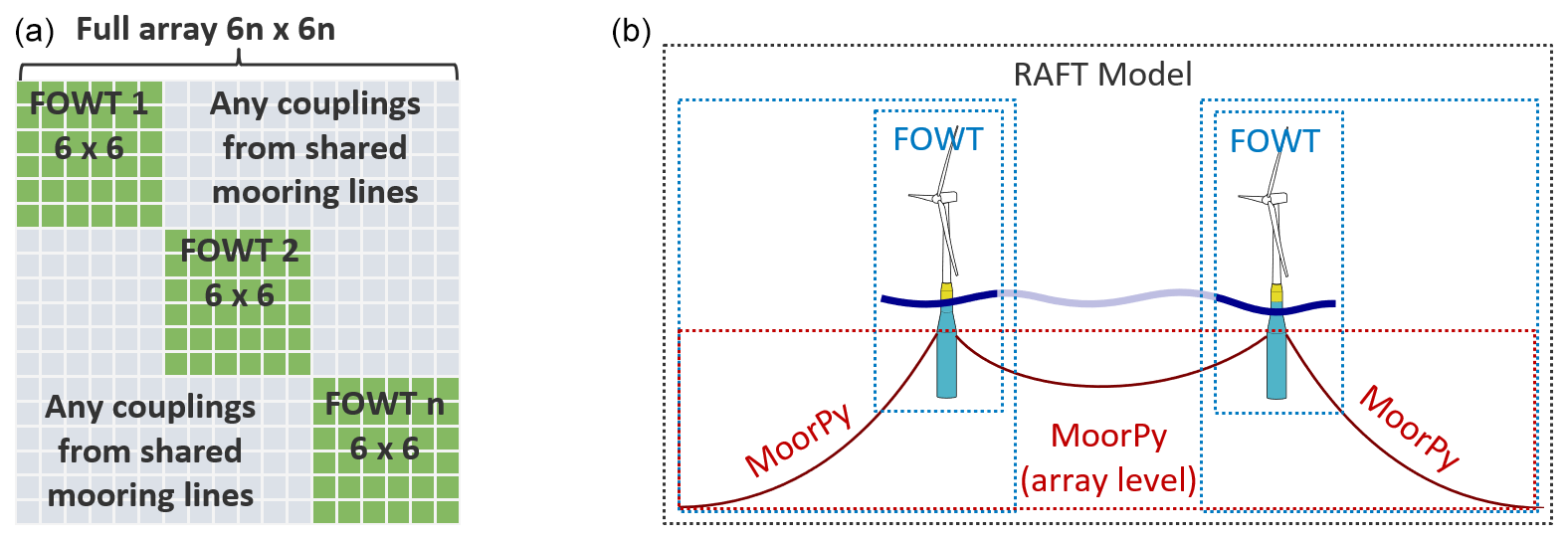
Figure 1Model structure for arrays including shared mooring lines: (a) matrix organization, (b) object structure.
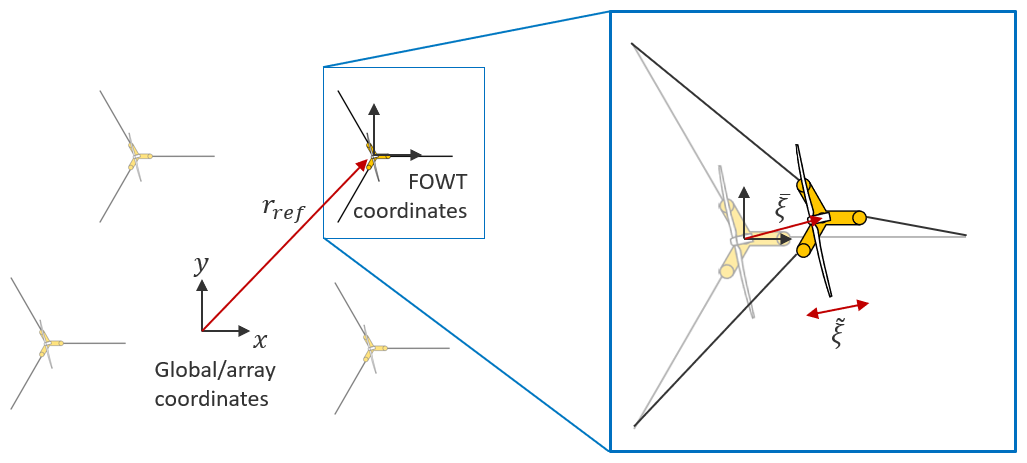
To relate individual FOWT properties to the full array, each FOWT object is given x and y reference coordinates in the vector rref that describe its undisplaced position relative to the global origin (Fig. 2). The calculation of each FOWT's response is relative to its reference position. For example, from the mean offset , a FOWT's mean position in global coordinates rglobal can be found by
For array applications, RAFT uses a two-level mooring system structure similar to FAST.Farm. Each FOWT can have its own independent system modeled by an individual MoorPy instance. In addition, the entire array can have an array-level mooring system that can include shared mooring lines or power cables running between FOWTs. Accordingly, for an array of n FOWTs, RAFT can have n+1 MoorPy instances. Each of these instances is optional – the only requirement is that each FOWT has mooring line attachments to provide station keeping. For example, Fig. 1 shows a case of two turbines with a shared mooring line in which RAFT could have three MoorPy instances: one for each of the two FOWT's independent mooring lines and one array-level instance for the shared mooring line between the FOWTs. Alternatively, all the mooring lines could be represented in the array-level instance.
2.3 Equilibrium solution process
To account for potential couplings between FOWTs, the process for finding equilibrium in RAFT has been revised. The equilibrium solution is now determined at the array level in RAFT rather than by MoorPy. This allows for the use of multiple MoorPy instances for the mooring systems in the array and will allow other system properties such as hydrostatic forces or wake effects to be updated in future work.
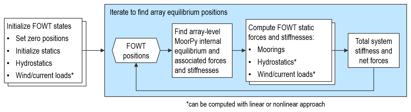
The equilibrium solution process uses an iterative Newton's method solver to determine the values of the 6n system degrees of freedom that equilibrate the forces and moments on the FOWTs. During each iteration, the positions and orientations of all FOWTs in the array are set based on the array's combined degrees-of-freedom vector rarray. Next, the forces and stiffnesses on each FOWT are updated based on the new positions and orientations, and the position adjustment is computed for the next iteration. This process can take either a linear or nonlinear approach, as outlined in Fig. 3.
The linear approach creates a hydrostatic stiffness matrix for each FOWT (Chs) up front and then uses that same matrix to compute updated hydrostatic forces with each iteration:
The nonlinear approach recomputes the hydrostatic forces of each FOWT based on the instantaneous position and orientation:
where is the structure weight and is the buoyancy. This new approach provides better support for unconventional platform geometries with nonlinear hydrostatics and, in the future, highly flexible substructures.
Similarly, the mean environmental loads from wind and currents () can either be calculated once and kept constant or updated every iteration based on how changes in the platform position or orientation affect the loads:
The calculation of these mean force components is described in previous work (Hall et al., 2022a, 2024). This approach would account for the reduction in turbine thrust force when the platform and turbine are pitched. It could also be used when including wake effects that depend on how much turbines offset into or out of each other's wakes (a phenomenon explored with RAFT in Lozon et al., 2024).
Because mooring systems are highly nonlinear, the mooring loads are always computed in a way that accounts for their nonlinearity. First, the mooring forces and moments of each FOWT's mooring system (if it exists) is computed directly from MoorPy:
where the introduced subscript i identifies a specific turbine in the array. Next, the mooring forces on each FOWT from the array-level MoorPy instance (if it exists) are calculated:
where the subscript “all” denotes the combined force or position vector of all turbines in the array.
Finally, the whole system's mean force vector is computed by combining the above terms:
For efficiency, the solution process uses analytic Jacobians (or stiffness matrices) rather than finite differencing. Stiffness contributions are computed at the same time as each of the force contributions described above. The hydrostatic and mooring stiffness computations are inherently available in the MoorPy (Hall, 2024) and RAFT calculation methods. Stiffness effects from environmental loadings acting at changing positions or orientations are currently neglected to avoid the need for numerical gradient calculations, since these terms are significantly smaller and unnecessary for convergence to the equilibrium. The stiffness terms from each FOWT and the array-level mooring system are combined in the equivalent format to the force combination process, Eq. (16), as follows:
where the hydrostatic stiffnesses can be kept constant or recomputed as a function of displacement, corresponding to Eqs. (11) and (12), respectively.
2.4 Wave headings and phases
In the present work, the environmental forces on each FOWT are computed independently; no array-level hydrodynamic interactions or wake effects are considered. This paper primarily focuses on shared mooring systems, which is discussed more in the next section.
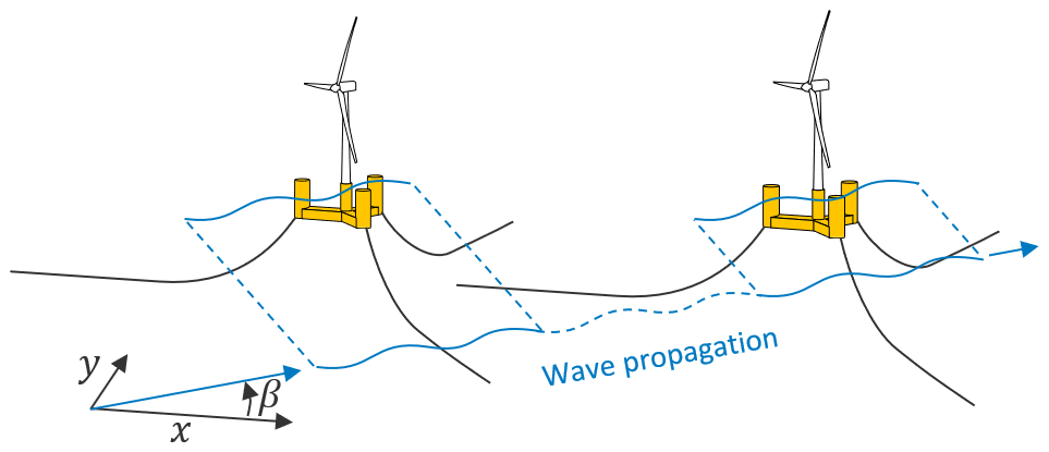
The main dynamic excitation affecting shared mooring lines is the phasing of wave loads between different turbines because the relative FOWT motions play a large role in the shared mooring system loads. Out-of-phase excitation from wind turbulence can also play a role, but wind turbulence is not considered in the present work. The relative phasing of wave loads on floating platforms in an array depends on the wave velocities and the platform's relative positions so the propagation of waves through the array needs to be accounted for.
We updated RAFT so that the wave loads for each platform are adjusted based on the mean platform positions and the wavelength vectors of each wave-frequency component. The wave phasing takes two forms according to whether hydrodynamics are modeled with strip theory or potential flow theory. For potential flow theory, a simple phase adjustment is applied to the wave excitation forces based on the FOWT's mean position, as follows:
where is the Fourier transform of the wave elevation at the platform's mean position (x, y), is the wave elevation at the farm origin, ω is wave frequency, k is wave number, and β is wave heading.
For strip theory hydrodynamics, the proper wave phasing is achieved by using the existing formulation described in Sect. 2.1 but providing the global coordinates when computing the local wave kinematics acting on the substructure. In other words, the wave kinematics of Eq. (5) are computed using a phase-shifted wave elevation as in Eq. (18), which inherently captures the proper phasing based on the position in the array.
Because RAFT does not resolve absolute phases, wave phase differences between turbines is only a relative phenomenon in RAFT. As a result, the implication of these phase differences is only for phenomena that are excited by relative motion, such as the loads felt by shared mooring lines, shared anchors, or fully suspended intra-array dynamic power cables.
Wave headings are handled directly by the strip theory approach, which is formulated in a 3-D way. For potential flow (linear) hydrodynamics, the frequency-dependent wave-excitation forces and moments can be computed by PyHAMS (through a built-in process in RAFT) or a priori with any preprocessor that produces excitation output files in the WAMIT format. Excitation data can be produced at a user-specified range of wave headings (such as at every 10°). Internally, RAFT interpolates the data to each wave heading that is being simulated.
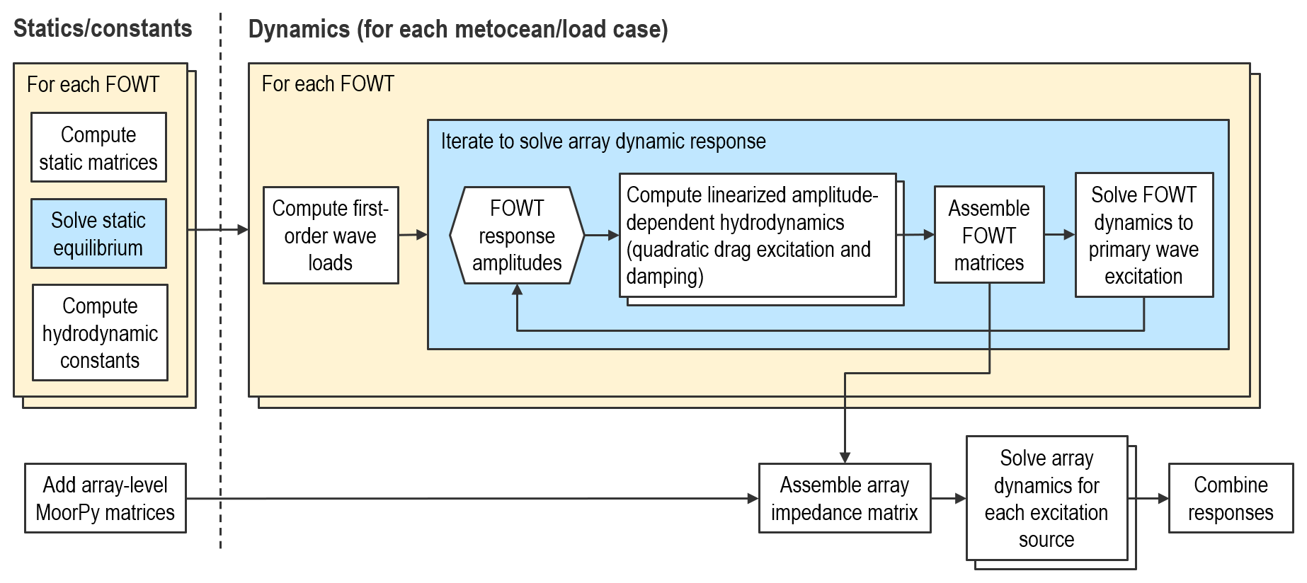
2.5 Coupled dynamic response
Calculating the dynamic response for arrays of floating wind turbines with possible couplings, outlined in Fig. 5, is considerably more complex than RAFT's original method for individual FOWTs (Hall et al., 2022a). First, RAFT computes the first-order response of each FOWT to wave excitation, including linearization of quadratic drag loads. This is done on a per-turbine basis and does not include the contribution of the array-level mooring system. In this way, the most computationally demanding step – the iterations when linearizing quadratic drag – is done on small system matrices for computational efficiency. For mooring systems that have a large influence on wave-frequency response, such as tension-leg platforms, the mooring system should be included in the FOWT-level MoorPy instance.
Once each FOWT response to wave excitation has been iteratively solved, the corresponding impedance matrix for each FOWT is saved:
This matrix represents the combined effects from all reaction-force phenomena acting on the FOWT (mass, hydrodynamics, hydrostatics, aerodynamic damping, etc.).
Next, a system-level impedance matrix is constructed by combining the FOWT-level impedance matrices, along with the stiffness terms of the array-level MoorPy instance if it exists:
This final impedance matrix can then be used with the array-level excitation vector to solve for the coupled dynamic response of all FOWTs in the array to all sources of excitation, including different sea states as well as wind excitation. Each source of excitation is assumed to be uncorrelated, so the system response is computed independently for each source. The squares of the frequency-dependent response magnitudes from each excitation source are then summed to compute the overall response statistics. For efficiency, the effect of shared mooring lines are neglected when computing each FOWT's motion amplitudes during the iterative drag linearization. Afterward, when computing the final full system response, all coupling effects are included.
2.6 Mooring tension response and shared mooring effects
Mooring system tensions in RAFT are modeled by superimposing mean tensions, which are computed directly by MoorPy, with tension amplitudes. The tension amplitudes are complex frequency-dependent values found by multiplying the FOWT response amplitudes by mooring tension Jacobians, which are computed at the mean mooring system state. The mooring tension Jacobian is the variation in mooring line end tension relative to the platform's degrees of freedom:
where τ is the vector of mooring line end tensions. This is calculated for each MoorPy instance, whether at the FOWT level or the array level.
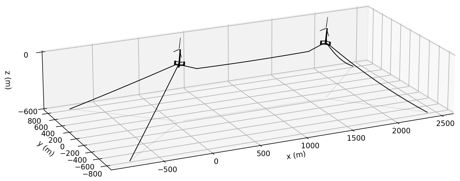
Figure 6The two-turbine shared mooring floating wind turbine array used for the verification.
Mooring line tension amplitudes are then computed for each mooring line based on the solved system response amplitudes:
and
Because each FOWT's entries in include the relative phase information based on each FOWT's position in the wave field, the tension responses of shared lines inherently capture the effect of relative motions between FOWTs.
The new array-level RAFT capabilities can be demonstrated by comparing with results from OpenFAST (Jonkman et al., 2024), which has a similar scope but significantly more fidelity. OpenFAST has been verified and validated in many prior studies and was used to verify RAFT's modeling for individual floating turbines in Hall et al. (2022a). Verifying new array-level features in RAFT requires the array equivalent of OpenFAST, FAST.Farm.
Table 3Mean values predicted by RAFT and FAST.Farm for different wind and wave directions.
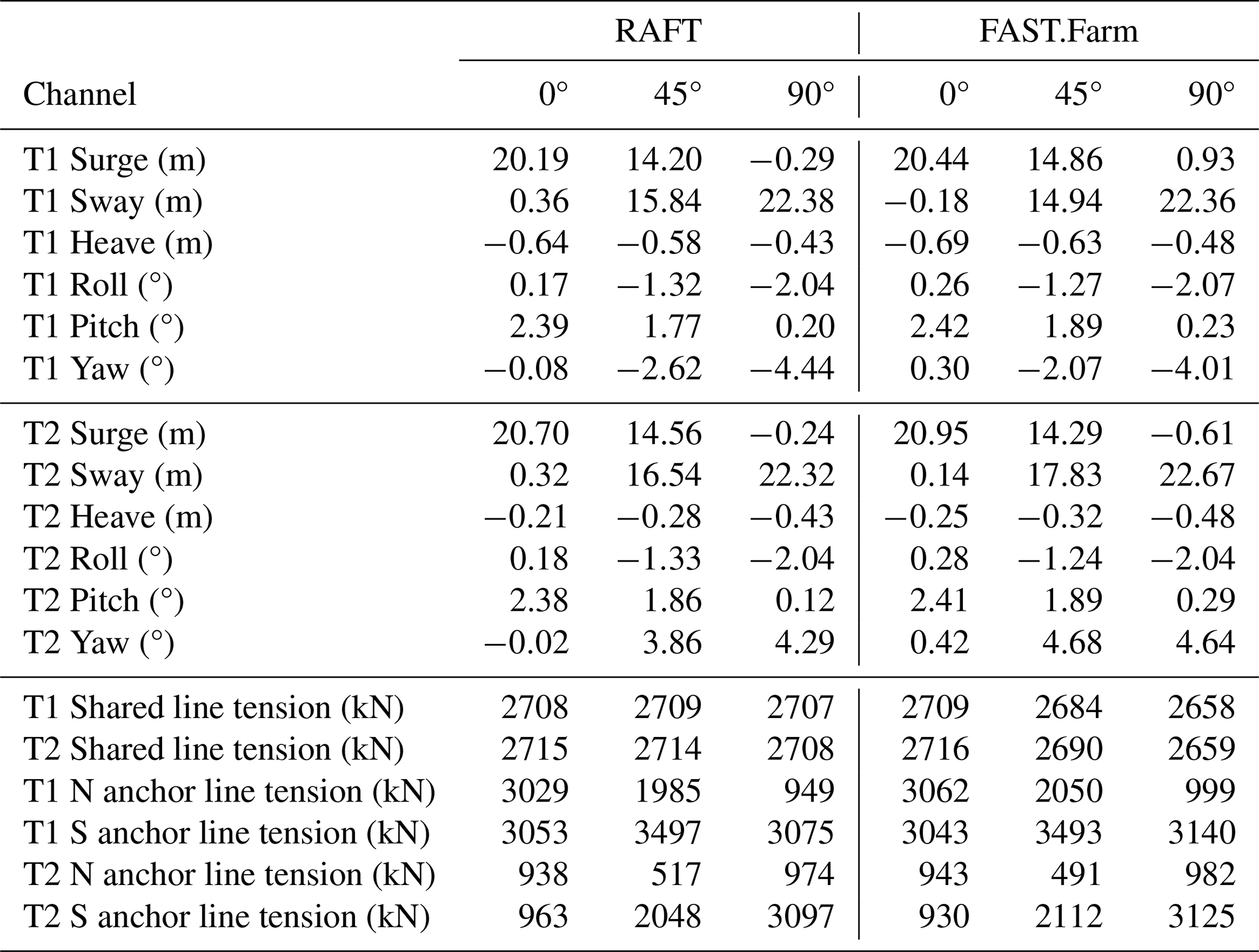

Figure 8Mean values obtained with RAFT and FAST.Farm for different wind and wave directions.
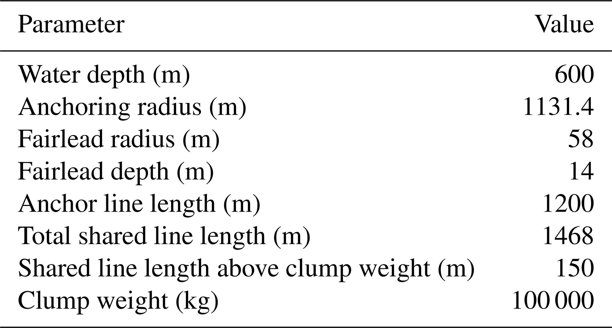
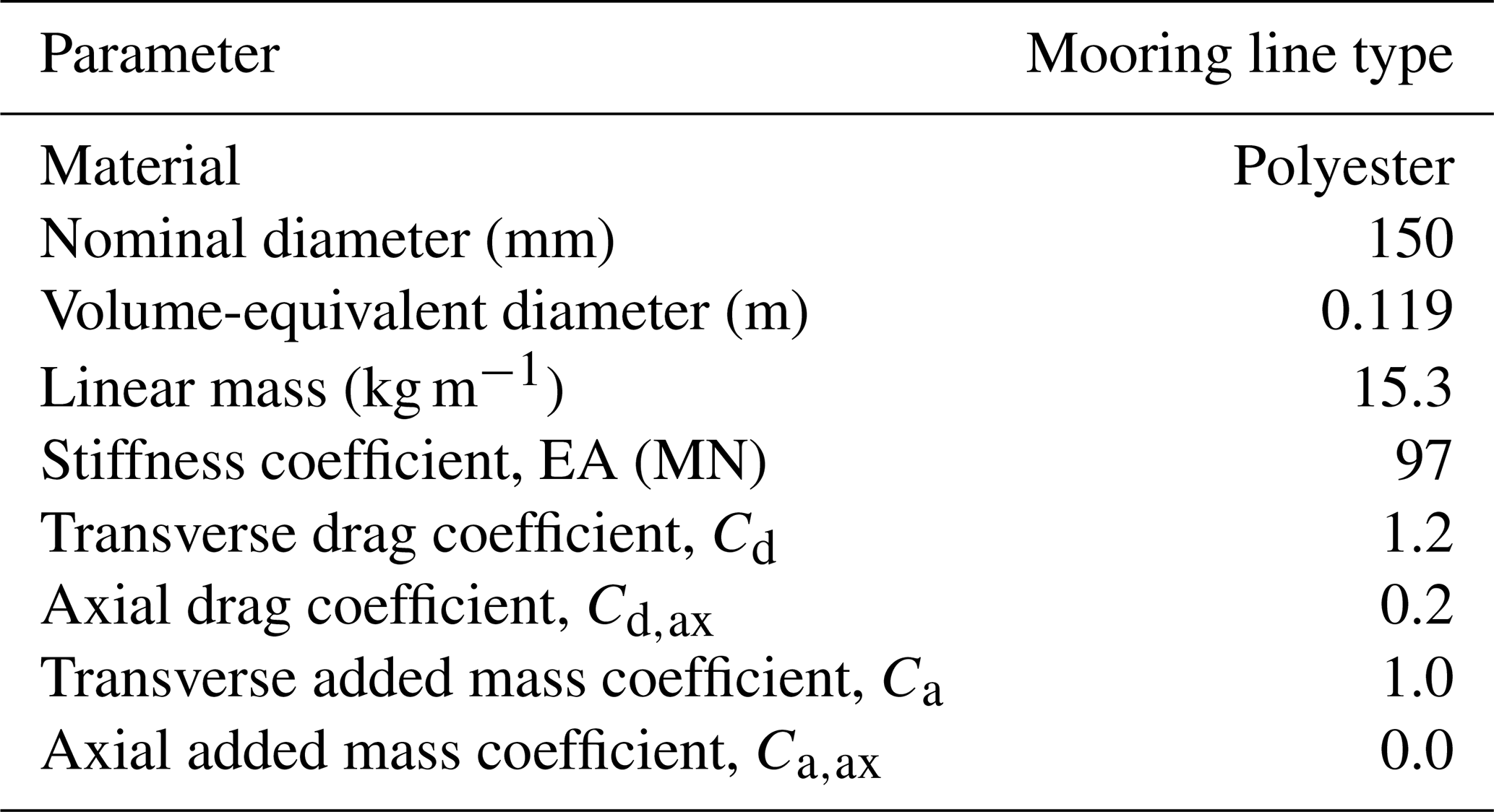
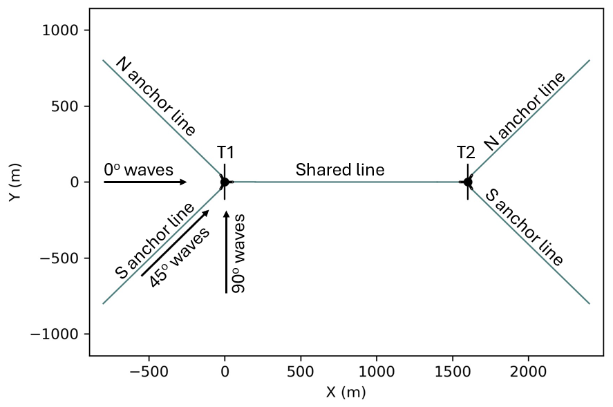
We present a verification that considers a simple two-turbine shared mooring array under wave excitation from multiple headings. The array consists of two FOWTs spaced 1600 m apart in 600 m water depth. Each FOWT is a VolturnUS-S semisubmersible floating platform (Allen et al., 2020) supporting the IEA Wind 15 MW reference turbine (Gaertner et al., 2020). There is one shared mooring line with two clump weights connecting the turbines. Each turbine also has two anchored mooring lines spread 90° apart. The mooring lines are polyester, and the configurations and dimensions are loosely based on the shared mooring design developed previously in Hall et al. (2022b), except the line stiffness has increased and the design has been adjusted accordingly. Figure 6 shows the design as plotted from RAFT. The shared mooring system design is summarized in Table 1, and the mooring line properties are shown in Table 2, including the hydrodynamic coefficients used in the MoorDyn model in FAST.Farm. The clump weights were modeled as a point mass with no volume or hydrodynamic properties.
A load case with steady wind and irregular waves is used to test the new RAFT features, since array effects from aerodynamics are left for future work. The case has an 8 m s−1 steady wind and a JONSWAP wave spectrum with a 12 s peak period and a 6 m significant wave height. Three wave headings are used: 0, 45, and 90° (Fig. 7). These three headings help to test that the array-level wave phase relationships are implemented properly. For simplicity, the wind is aligned with the waves in each case.
3.1 Mean offsets and tensions
Table 3 and Fig. 8 present the mean offsets and fairlead tensions calculated by RAFT and FAST.Farm. Mean tensions are included in RAFT's mean offset solution process. Figure 7 explains the nomenclature used for identifying the turbines and mooring lines in these results. The results show that RAFT matches the displacements and mooring line tensions computed by OpenFAST well, as would be expected considering that the model formulations are very similar for steady-state operation. This good level of agreement in both surge and pitch – and sway and roll for nonzero wind headings – indicates that the thrust force, the hydrostatic stiffness, and the mooring system stiffness are all in good agreement between models. The largest differences correspond to platform yaw, and they are still within the level of agreement expected from a low-fidelity model such as RAFT.
3.2 Dynamic response
The dynamic response of the coupled shared mooring floating array depends on the phasing of wave excitation on each platform and both the absolute and relative wave-induced motions. Figure 9 compares the power spectral density (PSD) of wave elevation between RAFT and FAST.Farm to confirm that the realization of the sea state is similar between models. The level of agreement is good, as expected, because both models set up the spectrum in a way that ensures the overall energy of the spectrum will match the targeted significant wave height.
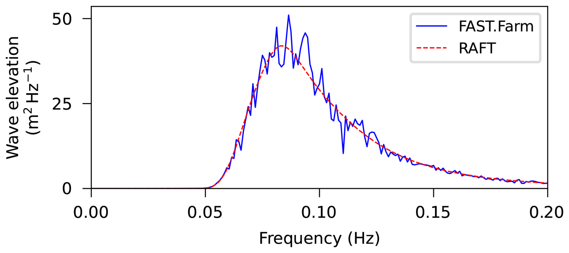
Figure 10 shows the PSDs of the 6 platform degrees of freedom for the first turbine from both RAFT and FAST.Farm. The figure shows generally good agreement, similar to what was seen in previous studies with a single turbine. The differences observed in roll and pitch can be explained by the strip theory hydrodynamic model in RAFT, which neglects wave radiation and wave scattering effects. These effects are included in FAST.Farm by using precomputed hydrodynamic coefficients obtained with WAMIT. RAFT can also use precomputed hydrodynamic coefficients, and the results shown from RAFT with WAMIT coefficients illustrate the closer agreement in the vertical degrees of freedom (heave, roll, and pitch) when including the wave radiation and wave scattering effects from WAMIT.
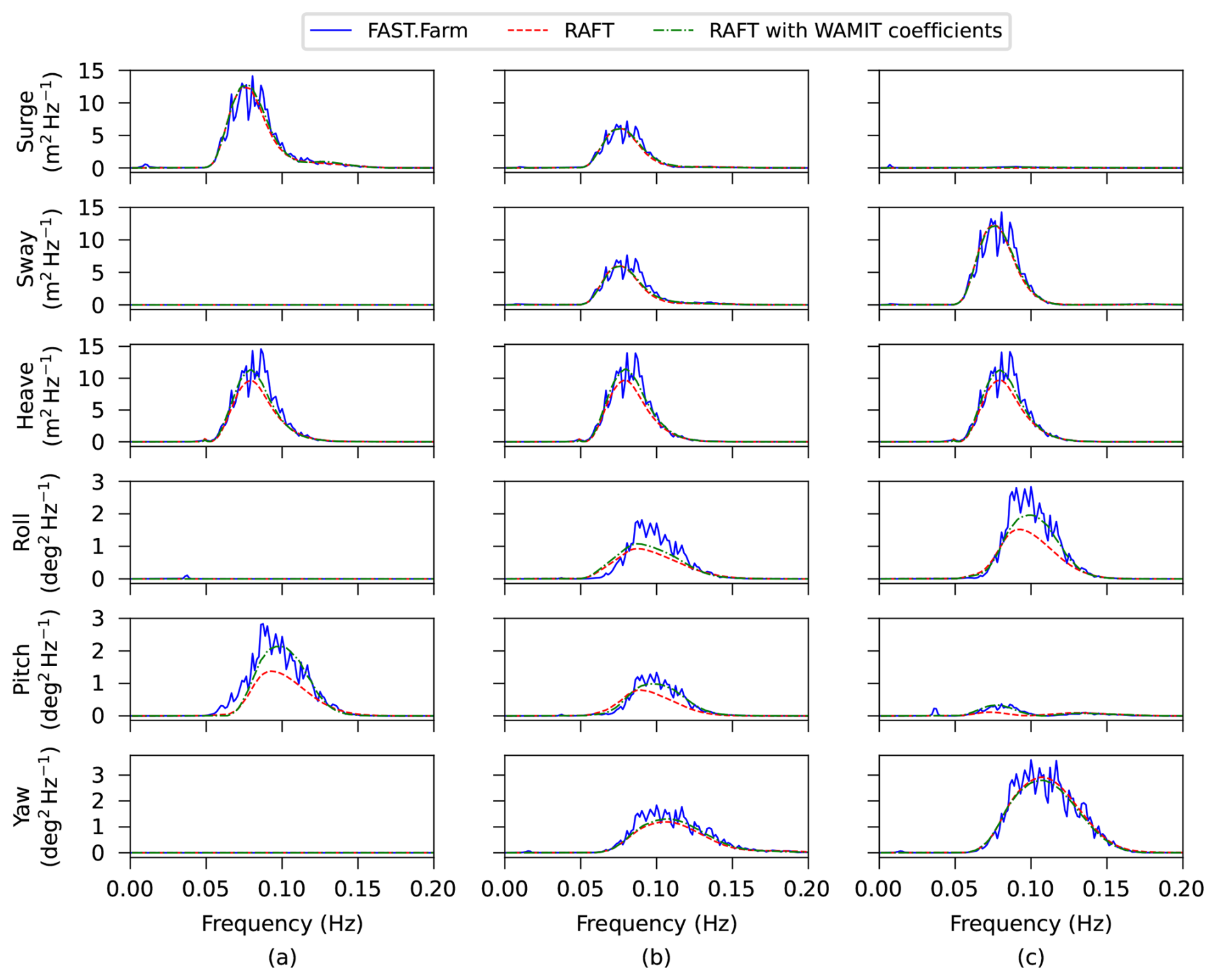
Figure 10Platform motion PSD for the first turbine in the array obtained with RAFT and FAST.Farm for (a) 0°, (b) 45°, and (c) 90° wind and wave headings.
Figure 11 shows the PSDs of the mooring line tension at the six attachment points to the floating platforms. The results show generally good agreement in both magnitude and frequency distribution, except for well-understood differences caused by RAFT's quasi-static model not accounting for mooring dynamics. Specifically, RAFT's tension predictions have less high-frequency content than OpenFAST's because MoorPy neglects hydrodynamic drag. Also, the RAFT results do not have shared mooring line excitation for the perpendicular wave direction because the distance between the turbines stays constant, and hydrodynamic drag on the mooring line is neglected. The level of agreement in the mooring line tensions is better than was seen previously in verification with the normal VolturnUS-S mooring system, which has a catenary chain at 200 m water depth. The better agreement is likely due to the large water depth and use of synthetic ropes, which generally have less dynamic effects and can therefore be better predicted by the quasi-static mooring model used in RAFT.
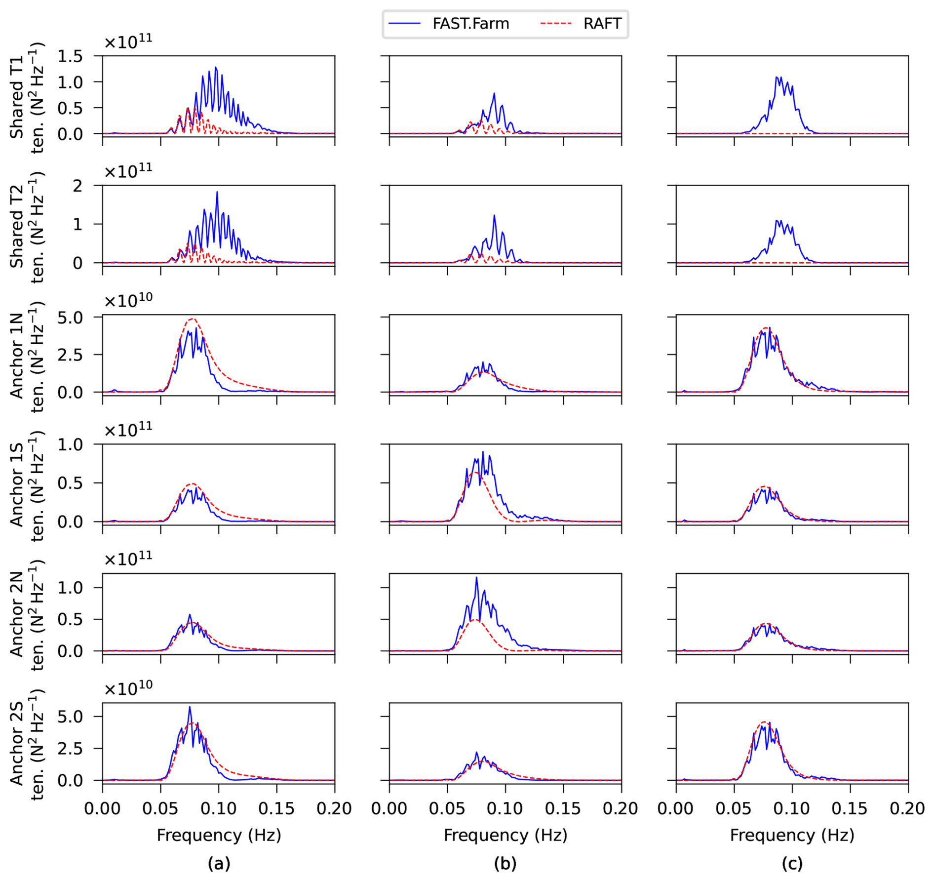
Figure 11Mooring tension PSD for each mooring fairlead obtained with RAFT and FAST.Farm for (a) 0°, (b) 45°, and (c) 90° wind and wave heading.
The good agreement in the shared mooring line tension PSDs at lower frequencies (around 0.06 Hz) suggests that the new shared mooring capabilities in RAFT are modeled correctly. The shared mooring line tensions in the 0 and 45° cases have a distinct comb-like frequency response, which we explore more in Sect. 4. Comparing the wind and wave headings in Fig. 11, the differences can be explained as follows:
-
In the 0° case, the waves are in line with the turbine arrangement, which results in relative motions in all excited degrees of freedom. This also results in strong excitation of the shared mooring line because it extends in the same direction as the relative motion.
-
In the 90° case, the waves are perpendicular to the turbine arrangement, so the turbines experience identical excitation (except for opposite directions of small yaw and pitch coupling effects because of the symmetry in their platform and mooring orientations), and the motion is perpendicular to the shared mooring line direction. Therefore, the shared line excitation is minimal except for the already discussed dynamic drag effects in the OpenFAST case.
-
In the 45° case, the motion in line with the shared mooring line is reduced, whereas new relative motions arise in sway and roll because the angled wave heading excites these degrees of freedom while also causing a phase difference in the excitation forces. The relative motions of the FOWTs are moderate in all the degrees of freedom, and the resulting shared line excitation is also moderate.
The dynamic response predictions can also be considered in terms of standard deviations, which are shown in Table 4 and Fig. 12. The FAST.Farm results are taken directly from FAST.Farm output time series, neglecting the first 20 min for startup transients, after which there was 1 h of simulation time. A single time-domain realization was used for each case for the purpose of making comparisons with frequency-domain results. The RAFT results are statistical calculations based on the predicted PSDs, using the strip theory hydrodynamic method. Consistent with the PSD results already presented, the standard deviation values agree fairly well between RAFT and OpenFAST. The largest relative differences are in the shared line tension results, an effect that was also present in the PSD results and attributed to the dynamic effects missing from MoorPy. There is also a notable difference in the turbine pitch response for the 0° case, especially for Turbine 1. This aligns with the PSD difference shown in Fig. 10, which is attributed to the use of strip theory in the RAFT results. The lesser difference in Turbine 2 pitch may be due to the effect of the shared line dynamics, but deeper investigation is beyond the present focus. Overall, the standard deviation results are within expectations considering the different model fidelity levels.
Table 4Standard deviation predicted by RAFT and FAST.Farm for different wind and wave directions.
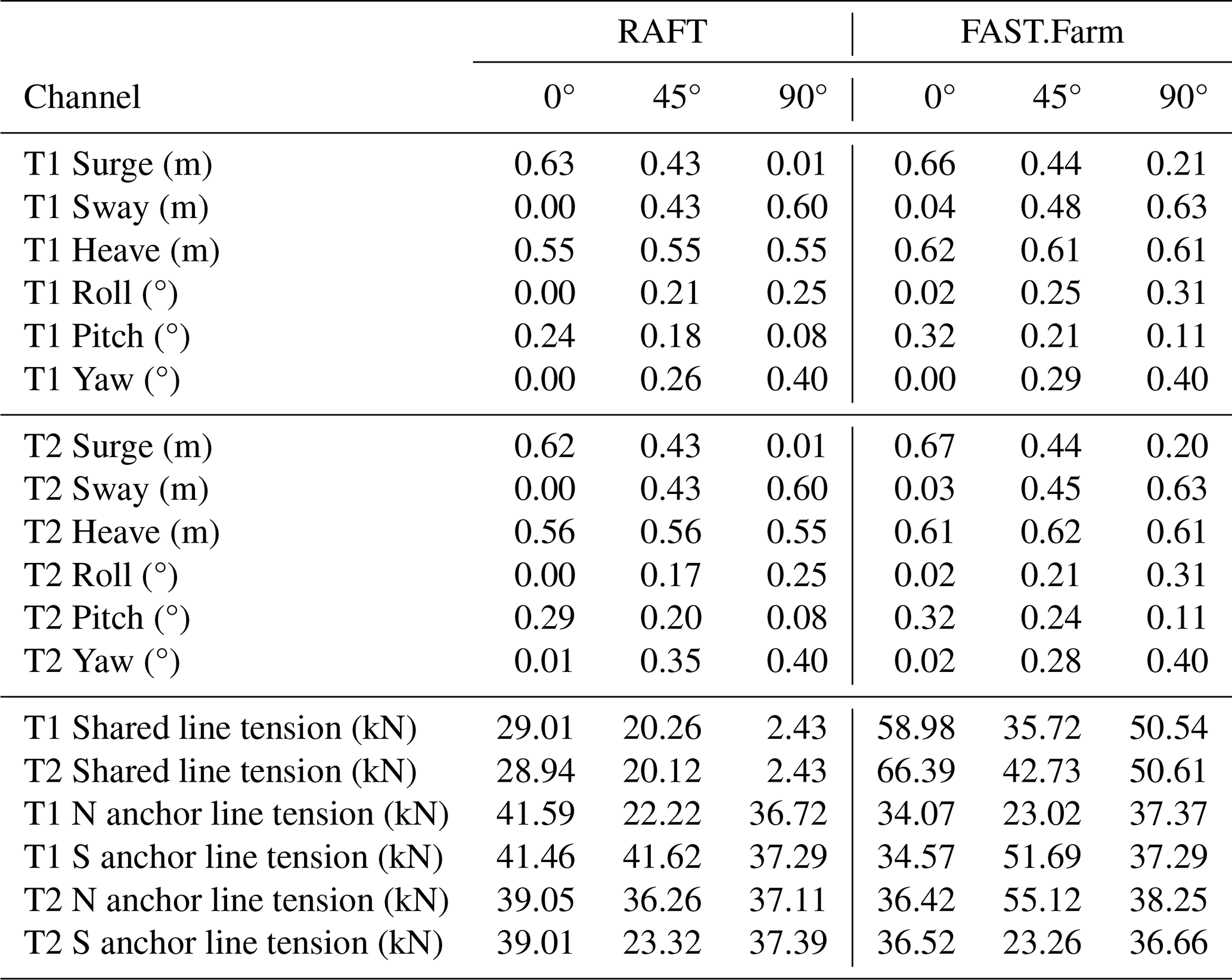
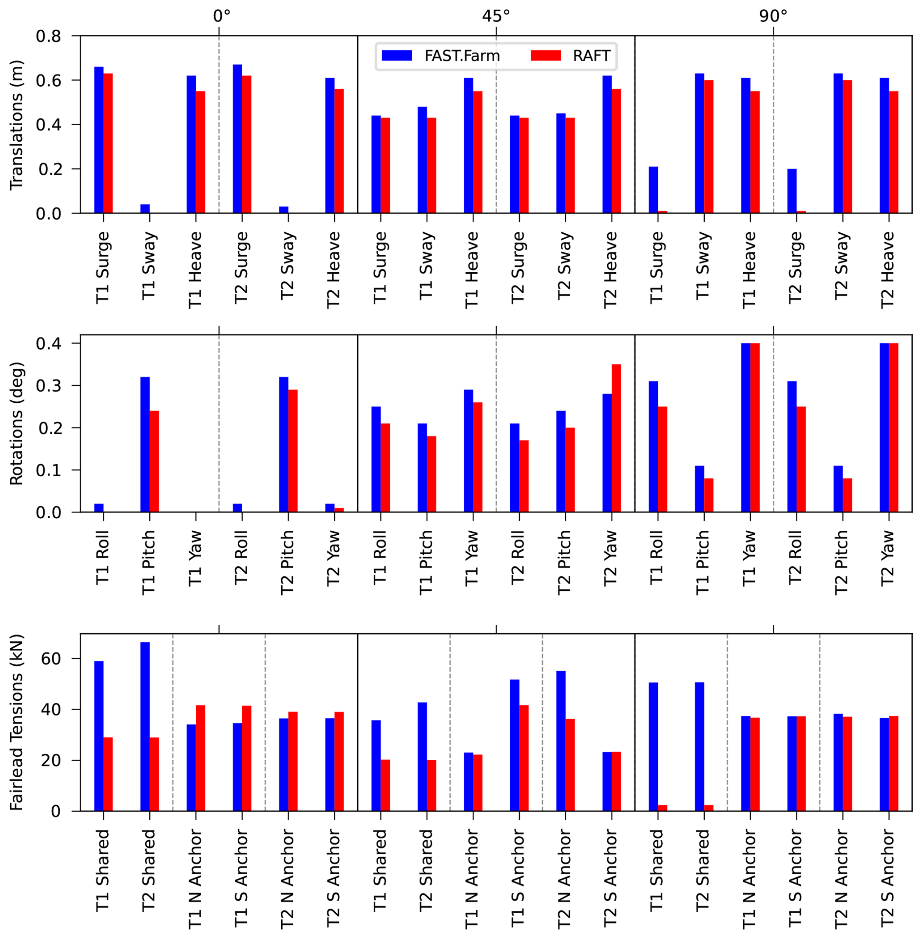
Figure 12Standard deviation obtained with RAFT and FAST.Farm for different wind and wave directions.
In addition to verifying RAFT's ability to model a shared mooring floating wind array's response, the results illuminate a phenomenon not previously discussed in the literature: a comb-like frequency response in the shared mooring line tensions. As visible in Fig. 11, this comb-like response is most noticeable in the results from RAFT, but it is also present in the OpenFAST results. The phenomenon can be understood by considering the relative motions of the floating platforms, which are the main driver of the shared mooring line tensions. Figure 13 plots the PSDs of the relative motions between the two platforms, along with the relative difference in wave elevations experienced by the two platforms. The comb-like response is visible in the PSD of relative wave elevation for the 0 and 45° wave headings. This can be explained mathematically by considering Eq. (18) and deriving the relative difference in wave elevation between two arbitrary locations:
The term within parentheses acts as an amplitude modulation, thus resulting in the comb-like PSD shown in Fig. 13. For the verification case discussed in this work, and y2=0, and the expression becomes
There is no amplitude modulation when the waves propagate perpendicularly to the turbine arrangement (wave heading of 90°) because the term within the parentheses becomes zero.
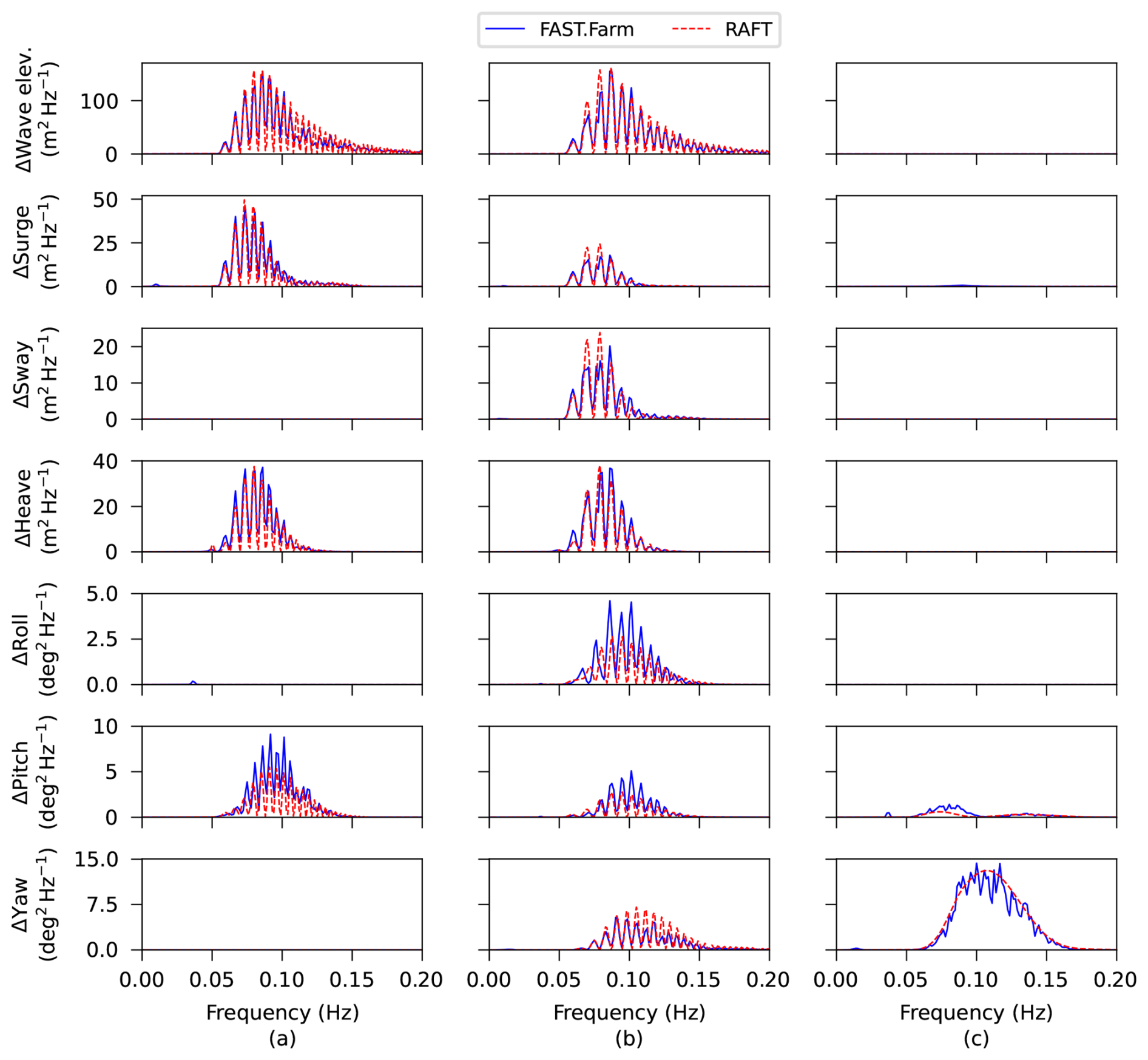
Figure 13PSDs of relative wave elevation and relative motions between T1 and T2 obtained with RAFT and FAST.Farm for (a) 0°, (b) 45°, and (c) 90° wind and wave headings.
To further illustrate the origins of the behavior, Fig. 14 plots the wave elevation at the origin, the surge motion of each turbine, and the shared mooring line tension complex amplitudes versus frequency. The complex amplitudes provide a raw view of what RAFT is calculating because they also contain phase information. The phases can be inferred from the real and imaginary components, which are included in the plots. For simplicity, RAFT assumes that every frequency component of the wave elevation is at zero phase offset at the wind farm origin. Turbine 1 has a reference position at the origin, resulting in wave elevations with close to zero phase offset (the wave complex amplitudes have close to zero imaginary component). There is a phase lag in its surge response (appearing as a negative imaginary component in the complex amplitude) because of the phase lag inherent in the fluid–structure interaction. Turbine 2 has a similar fluid–structure response, but it also experiences a phase shift in the wave elevations because of its offset location. The phase shift is approximately proportional to frequency. Because of the large spacing relative to the wavelengths, the phase shift “wraps around” approximately 10 times within the wave excitation frequency range, which is shown by the number of peaks in the real component curve in the T2 surge plot in Fig. 14a, b.
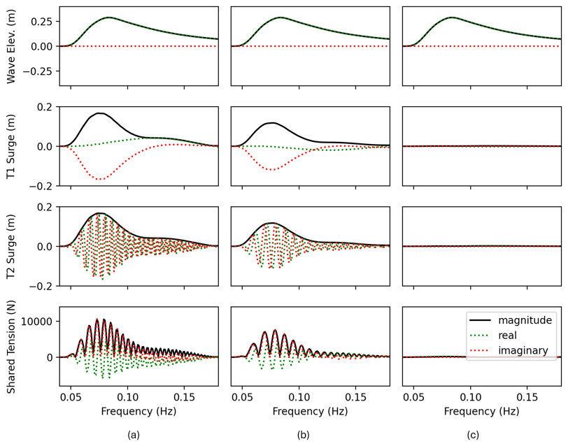
Figure 14Complex response amplitudes predicted by RAFT for (a) 0°, (b) 45°, and (c) 90° wave headings.
Excitation of tensions in the shared mooring line depends primarily on relative motion between the floating platforms. Because Turbine 2 has a phase shift that wraps around many times, the relative phase between Turbines 1 and 2 has a similar wrap-around behavior, meaning that the turbines alternate between moving in phase and out of phase with each other across the frequency range. As a result, the shared mooring line tension spectrum alternates between zero (at frequencies where the turbines surge in phase) and a peak (at frequencies where the turbines surge out of phase). The positions of the zero-magnitude values in the shared mooring line tension plot correspond to the wavelengths that are multiples of the distance between T1 and T2.
This result is reasonable in theory and perhaps important as a design consideration in certain scenarios that are expected to result in primarily out-of-phase motions. This behavior is expected to be less pronounced under short-crested waves due to directional spreading, but it is probably noticeable in highly directional seas such as swells. The result is less distinct in the FAST.Farm results because of the increased broadband excitation and nonlinearities in the time-domain simulations. Further exploration of this comb-like shared line excitation phenomenon using both modeling approaches could be helpful to better understand its implications for design. The phenomenon would be equally applicable to assessing the loads on shared anchors, since the net horizontal loads are also affected by relative motions of the attached FOWTs.
The RAFT frequency-domain dynamics model for floating wind turbines was expanded to simulate arrays of floating wind turbines with the possibility of shared mooring lines. An approach to capture phase differences in the wave loadings of each floating wind turbine, along with the resulting differences in their responses, makes it possible to accurately predict the tension dynamics of shared mooring lines running between turbines.
The capability was verified by comparing against FAST.Farm simulation results for a simple two-turbine case with a single shared mooring line. The results show generally good agreement. The results in shared mooring line tension agree particularly well between models, except for well-understood limitations of the quasi-static mooring model that is used by RAFT. Improved mooring tension agreement compared to previous single-turbine comparisons is likely due to the use of a taut mooring system in the present study, which reduces the importance of dynamic effects compared to catenary mooring systems.
In addition to verifying the new array-level modeling features, the results illuminated a previously unknown phenomenon in which shared mooring lines are excited at a comb-like frequency response. This occurs because of the nature of relative motion between adjacent platforms that experience wave excitation phase shifts. The phenomenon is more obscured in time-domain results and warrants further exploration using a range of modeling methods to better understand its implications for design.
The present study focused on first-order wave excitation and did not consider excitation from second-order wave loads or from wind turbulence. These are important areas for future work. Second-order wave excitation capabilities have been recently added to RAFT (Carmo and Hall, 2025) and could be extended to work for array scenarios. Turbulent wind excitation is an ongoing development effort for RAFT but will likely be an important source of excitation and array-level interactions. In addition, the potential to account for mooring system dynamics in the frequency domain, as recently developed by Abdelmoteleb and Bachynski-Polić (2025), could reduce the modeling differences between the frequency- and time-domain approaches and shed further light on the underlying dynamic phenomena in shared mooring systems.
The RAFT and OpenFAST modeling codes used in this work are both open-source and available through public repositories hosted on GitHub. For RAFT, see Hall et al. (2025). For OpenFAST, see Jonkman et al. (2024).
The reference floating wind turbine design used in this study has input data publicly available in several locations. The central repository of the design is at https://github.com/IEAWindSystems/IEA-15-240-RWT. The input files for RAFT are included in the RAFT repository (Hall et al., 2025). The two-turbine shared mooring configuration is fully described in this paper, and any questions can be sent to the corresponding author.
MH conceived the original concept and obtained the funding for the research. MH and LC developed the modeling methods. All authors ran the simulations and analyzed the results. All authors contributed to the writing and jointly finalized the paper.
The contact author has declared that none of the authors has any competing interests.
The views expressed in the article do not necessarily represent the views of the DOE or the U.S. Government.
Publisher's note: Copernicus Publications remains neutral with regard to jurisdictional claims made in the text, published maps, institutional affiliations, or any other geographical representation in this paper. While Copernicus Publications makes every effort to include appropriate place names, the final responsibility lies with the authors. Views expressed in the text are those of the authors and do not necessarily reflect the views of the publisher.
This work was authored by NREL for the US Department of Energy (DOE) under contract no. DE-AC36-08GO28308. The US Government retains and the publisher, by accepting the article for publication, acknowledges that the US Government retains a nonexclusive paid-up irrevocable worldwide license to publish or reproduce the published form of this work, or allow others to do so, for US Government purposes.
Funding for this study has been provided by the DOE Office of Energy Efficiency and Renewable Energy Wind Energy Technologies Office through the Floating Wind Array Design project.
This paper was edited by Erin Bachynski-Polić and reviewed by three anonymous referees.
Abdelmoteleb, S.-E. and Bachynski-Polić, E. E.: A frequency-domain optimization procedure for catenary and semi-taut mooring systems of floating wind turbines, Marine Structures, 101, 103768, https://doi.org/10.1016/j.marstruc.2024.103768, 2025. a
Allen, C., Viselli, A., Dagher, H., Goupee, A., Gaertner, E., Abbas, N., Hall, M., and Barter, G.: Definition of the UMaine VolturnUS-S reference platform developed for the IEA Wind 15-Megawatt offshore reference wind turbine, Tech. Rep. NREL/TP-5000-76773, National Renewable Energy Laboratory, https://doi.org/10.2172/1660012, 2020. a
Barltrop, N. (Ed.): Floating structures: a guide for design and analysis, Oilfield Publications Limited (OPL), Ledbury, England, ISBN: 978-1-87055-3353, 1998. a
Carmo, L. and Hall, M.: Slender-body approach for computing second-order wave loads in the frequency domain, Ocean Engineering, 322, https://doi.org/10.1016/j.oceaneng.2025.120558, 2025. a
Chen, P., Cheng, Z., Deng, S., Hu, Z., and Moan, T.: A frequency domain method for fully coupled modelling and dynamic analysis of floating wind turbines, Marine Structures, 99, 103715, https://doi.org/10.1016/j.marstruc.2024.103715, 2025. a
Connolly, P. and Hall, M.: Comparison of pilot-scale floating offshore wind farms with shared moorings, Ocean Engineering, 171, 172–180, https://doi.org/10.1016/j.oceaneng.2018.08.040, 2019. a
Ding, Q., Li, C., Yu, N., Hao, W., and Ji, J.: Numerical and experimental investigation into the dynamic response of a floating wind turbine spar array platform, Journal of Mechanical Science and Technology, 32, 1106–1116, https://doi.org/10.1007/s12206-018-0213-x, 2018. a
Faltinsen, O.: Sea loads on ships and offshore structures, Cambridge University press, ISBN: 9780521458702, 1993. a
Gaertner, E., Rinker, J., Sethuraman, L., Zahle, F., Anderson, B., Barter, G. E., Abbas, N. J., Meng, F., Bortolotti, P., Skrzypinski, W., Scott, G. N., Feil, R., Bredmose, H., Dykes, K., Shields, M., Allen, C., and Viselli, A.: IEA Wind TCP Task 37: Definition of the IEA 15-Megawatt offshore reference wind turbine, Tech. Rep. NREL/TP-5000-75698, National Renewable Energy Laboratory, https://doi.org/10.2172/1603478, 2020. a
Goldschmidt, M. and Muskulus, M.: Coupled mooring systems for floating wind farms, Energy Procedia, 80, 255–262, https://doi.org/10.1016/j.egypro.2015.11.429, 2015. a
Gözcü, O., Kontos, S., and Bredmose, H.: Dynamics of two floating wind turbines with shared anchor and mooring lines, Journal of Physics: Conference Series, 2265, 042026, https://doi.org/10.1088/1742-6596/2265/4/042026, 2022. a
Hall, M.: Generalized quasi-static mooring system modeling with analytic jacobians, Energies, 17, 3155, https://doi.org/10.3390/en17133155, 2024. a
Hall, M. and Connolly, P.: Coupled dynamics modelling of a floating wind farm with shared moorings, in: Proceedings of the ASME 2018 37th International Conference on Ocean, Offshore and Arctic Engineering, ASME, Madrid, Spain, https://doi.org/10.1115/OMAE2018-78489, 2018. a
Hall, M., Buckham, B., and Crawford, C.: Evolving offshore wind: Genetic algorithm-based optimization of floating wind turbine platforms, in: MTS/IEEE Oceans'13, Bergen, Norway, 2013, 1–10, https://doi.org/10.1109/OCEANS-Bergen.2013.6608173, 2013. a
Hall, M., Carmo, L., Housner, S., Zalkind, D., and Barter, G.: RAFT: v1.5, Zenodo [code], https://doi.org/10.5281/zenodo.17808357, 2025.
Hall, M., Housner, S., Zalkind, D., Bortolotti, P., Ogden, D., and Barter, G.: An open-source frequency-domain model for floating wind turbine design optimization, Journal of Physics: Conference Series, 2265, 042020, https://doi.org/10.1088/1742-6596/2265/4/042020, 2022a. a, b, c, d, e, f
Hall, M., Lozon, E., Housner, S., and Sirnivas, S.: Design and analysis of a ten-turbine floating wind farm with shared mooring lines, Journal of Physics: Conference Series, 2362, 012016, https://doi.org/10.1088/1742-6596/2362/1/012016, 2022b. a, b
Hall, M., West, W., Housner, S., and Lozon, E.: Efficient modeling of floating wind arrays including current loads and seabed bathymetry, in: Proceedings of the ASME 2023 5th International Offshore Wind Technical Conference, 18–19 December 2023, Exeter, UK, https://doi.org/10.1115/IOWTC2023-119447, 2024. a
Hegseth, J. M., Bachynski, E. E., and Martins, J. R. R. A.: Integrated design optimization of spar floating wind turbines, Marine Structures, 72, https://doi.org/10.1016/j.marstruc.2020.102771, 2020. a
Jonkman, B., Platt, A., Mudafort, R., Branlard, E., Sprague, M., Ross, H., Slaughter, D., Jonkman, J., Hayman, G., cortadocodes3, Hall, M., Vijayakumar, G., Buhl, M., Russell9798, Bortolotti, P., Davies, R., reos-rcrozier, Ananthan, S., Michael, S., Rood, J., Damiani, R., Mendoza, N., sinolonghai, pschuenemann, Chetan, M., Sharma, A., Shaler, K., Housner, S., Wang, L., and psakievich: OpenFAST/openfast: v4.0.0, Zenodo [code], https://doi.org/10.5281/zenodo.14553563, 2024.
Lemmer, F., Yu, W., Luhmann, B., Schlipf, D., and Cheng, P. W.: Multibody modeling for concept-level floating offshore wind turbine design, Multibody System Dynamics, 49, 203–236, https://doi.org/10.1007/s11044-020-09729-x, 2020. a
Liang, G., Merz, K., and Jiang, Z.: Modeling of a shared mooring system for a dual-spar configuration, in: Proceedings of the ASME 2020 39th International Conference on Ocean, Offshore and Arctic Engineering, 3–7 August 2020, virtual conference, https://doi.org/10.1115/OMAE2020-18467, 2020. a
Lozon, E. and Hall, M.: Coupled loads analysis of a novel shared-mooring floating wind farm, Applied Energy, 332, 120513, https://doi.org/10.1016/j.apenergy.2022.120513, 2023. a
Lozon, E., Hall, M., and Mahfouz, M. Y.: Coupled modeling of wake steering and platform offsets for floating wind arrays, Journal of Physics: Conference Series, 2767, 062035, https://doi.org/10.1088/1742-6596/2767/6/062035, 2024. a
Lupton, R. C. and Langley, R. S.: Improved linearised models of wind turbine aerodynamics and control system dynamics using harmonic linearisation, Renew. Energy, 135, https://doi.org/10.1016/j.renene.2018.11.067, 2019. a
Morison, J., O'Brien, M., Johnson, J., and Schaaf, S.: The force exerted by surface waves on piles, Journal of Petroleum Technology, 2, 149–154, https://doi.org/10.2118/950149-G, 1950. a
Munir, H., Lee, C. F., and Ong, M. C.: Global analysis of floating offshore wind turbines with shared mooring system, IOP Conference Series: Materials Science and Engineering, 1201, 012024, https://doi.org/10.1088/1757-899x/1201/1/012024, 2021. a
Pegalajar-Jurado, A., Borg, M., and Bredmose, H.: An efficient frequency-domain model for quick load analysis of floating offshore wind turbines, Wind Energ. Sci., 3, 693–712, https://doi.org/10.5194/wes-3-693-2018, 2018. a
Wayman, E.: Coupled dynamics and economic analysis of floating wind turbine systems, Masters thesis, MIT, Massachusetts Institute of Technology, http://hdl.handle.net/1721.1/35650 (last access: 23 February 2016), 2006. a
Wilson, S., Hall, M., Housner, S., and Sirnivas, S.: Linearized modeling and optimization of shared mooring systems, Ocean Engineering, 241, 110009, https://doi.org/10.1016/j.oceaneng.2021.110009, 2021. a
Yang, C., Xiao, L., Chen, P., Cheng, Z., Liu, M., and Liu, L.: An analytical frequency-domain model of aerodynamic mass and damping of floating wind turbines, Wind Energy, 26, 1140–1164, https://doi.org/10.1002/we.2861, 2023. a