
the Creative Commons Attribution 4.0 License.
the Creative Commons Attribution 4.0 License.
 | 09 Sep 2026
Virtual sensing for strain estimation in wind turbine support structures based on a biaxial accelerometer
Jonathan Thurn

Clemens Jonscher
Benedikt Hofmeister
Gianluca Zorzi
Raimund Rolfes
This paper introduces a novel model-based approach for virtual sensing of wind turbine support structures for full-field strain estimation using a single biaxial, DC-capable accelerometer and a sufficiently accurate structural model. It enables displacement and strain estimation in the quasi-static frequency band, which accounts for a large proportion of accumulated fatigue damage in offshore wind turbine support structures while saving costs by relying solely on accelerations from a single accelerometer as input. The introduced method extends the modal decomposition and expansion by using displacement estimations based on tilt-error-compensated acceleration time series, utilising the tower's static bending line. It is applied here in two validation case studies: a small-scale laboratory experiment and a full-scale offshore wind turbine. In both cases, the estimated strain is validated against strain measurements conducted at various locations along the structure. The results show excellent agreement between the estimated and measured strains for both case studies. In the laboratory experiment, both displacements and strains are estimated accurately with errors below 2.2 % and 5 %, respectively. For the offshore wind turbine, the damage-equivalent loads at the transition piece can be estimated with a mean percentage error of below 9 %. The remaining errors can be attributed to modelling uncertainties and simplified load assumptions. The presented approach offers an improvement over established methods for strain estimation, achieving similar accuracy with fewer sensors, resulting in a low-maintenance load monitoring.
- Article
(3472 KB) - Full-text XML
- BibTeX
- EndNote


With the increasing number of offshore wind turbine (OWT) installations over the last decades, a significant number of OWTs will reach the end of their typical design lifetime of 20–25 years in the coming years (WindEurope, 2025), leading to questions about the end-of-life strategies, which will become even more important in the years to come. Due to incomplete understanding of aerodynamics, soil mechanics and expected environmental conditions, uncertainties in the design loads and structural resistance are relatively high in OWTs, especially compared to other types of power-generating turbines. Experience shows that the structural properties assumed in design often deviate from the as-built turbine support structure, which becomes apparent from deviations in the eigenfrequencies of the actual OWT when compared to those expected in the design phase (Augustyn et al., 2020; Sastre Jurado et al., 2024). To account for these uncertainties, OWTs are designed with partial safety factors (DNV-GL, 2016), often resulting in conservative designs (Natarajan et al., 2020). Knowledge about the actual fatigue-relevant loading acting on the OWT could therefore be used to justify an extension of the OWT’s service life beyond the design lifetime (Ziegler and Muskulus, 2016). Furthermore, load monitoring can also serve as a basis for longer service lives through an optimised operation that takes into account the fatigue effects of unforeseen operational conditions, such as frequent curtailments.
To monitor the loads acting on an OWT, it can be equipped with sensors, such as strain gauges or acceleration sensors, to measure its structural response. Usually, the turbine operator is interested in the structural response at various relevant elevations of the structure (Tarpø et al., 2020). However, equipping the structure with sensors at every critical position is not always possible nor cost-effective and therefore not feasible in practice (Farrar and Worden, 2012). To overcome this limitation, virtual sensing methods can be used. In virtual sensing, non-physical sensors are synthesised from physical sensor time series data and a structural or data-based model to estimate quantities at positions without sensors. In the context of wind turbines, virtual sensing is often used to estimate strain at unmeasured locations since the critical point for the fatigue design is close to the mudline, where strain sensors cannot usually be installed. For this reason, virtual sensing methods for OWTs are also often referred to as strain estimation, strain prediction or fatigue prediction methods (Tarpø, 2020).
The most widely used methods for virtual sensing for OWTs are based on the modal decomposition and expansion (MDE), the Kalman filter (Tarpø, 2020) and machine learning (ML) techniques. In their simplest form, these approaches use only acceleration measurements as input for the strain estimation. The Kalman filter was first applied for virtual sensing by Papadimitriou et al. (2011) and estimates a state-space model that is updated continuously using measurement data. By combining information from the state-space model with measurements, the Kalman filter can reduce uncertainty in the estimation compared to purely data-based or purely model-based approaches. The Kalman filter has been applied for strain estimation of wind turbine support structures in several publications, such as Maes et al. (2015, 2016) and Branlard et al. (2020), as well as in modified versions such as by Zou et al. (2023). The majority of research in the field of virtual sensing is, however, based on the MDE. The MDE algorithm, as it is known today, was introduced by Hjelm et al. (2005) and Graugaard-Jensen et al. (2005). In the MDE, the structural response is decomposed and reconstructed using the structure's mode shapes, usually extracted from a finite-element model and vibration measurement data, typically acquired using accelerometers. In many applications, the structural response is dominated by a few modes only, allowing sufficiently accurate strain estimation despite using only a limited number of sensors (Baqersad et al., 2015). The MDE or modifications to the MDE have been used for strain estimation of wind turbines in multiple publications, such as Tarpø et al. (2020), Maes et al. (2016) and Nabuco et al. (2020). Additionally, other methods based on machine learning exist, such as those described by Tarpø et al. (2022), Moynihan et al. (2024) and Bilbao et al. (2022). In Bilbao et al. (2022), it is also shown that a significant portion of fatigue-relevant damage is neglected when only dynamic stresses above 0.1 Hz are considered, highlighting a limitation of many virtual sensing approaches for OWTs: the methods perform well for estimating the dynamic strain but fail to accurately capture the response well below the first eigenfrequency, denoted here as the quasi-static frequency range (Maes et al., 2016; Iliopoulos et al., 2017). Although no formal definition exists for this quasi-static frequency range, it is generally understood to encompass frequencies significantly lower than the first eigenfrequency and below 0.1 Hz.
For many structures, the quasi-static response has negligible effects on the fatigue life consumption since only few low-frequency load cycles occur over the structure's lifetime. However, for wind turbines, the quasi-static response is fatigue-relevant (Bilbao et al., 2022; Tarpø et al., 2025), as large displacements and thus strains are associated with the quasi-static part of the excitation (Augustyn et al., 2021; Iliopoulos et al., 2017; Noppe et al., 2016), caused by wind gusts and yawing motion. In contrast, the excitation in the dynamic frequency band occurs due to wind turbulence, waves and periodic rotor excitation. Therefore, neglecting the quasi-static frequency range leads to a significant underestimation of fatigue loads and is therefore not conservative. This is shown as an example in Fig. 1 for a 1 h strain time series of an OWT tower. If the quasi-static component of the strain set here to below 0.1 Hz is neglected, the fatigue damage, expressed here via the damage-equivalent strain (DES), is significantly underestimated, only adding up to about 69 % of the actual DES. Similarly, it is not sufficient to consider the quasi-static frequency range only since the dynamic frequency range, including vibrations close to the first eigenfrequency and those excited by rotor rotation, also contributes to the fatigue loading.

Figure 1Strain time series of an offshore wind turbine tower under partial load operation. The low-pass- and high-pass-filtered signals were obtained using zero-phase fourth-order Butterworth filters with a crossover frequency of 0.1 Hz. The first bending eigenfrequency (EF) of the tower is indicated. The damage-equivalent strain (DES) is normalised with respect to the total DES of the unfiltered signal.
Estimating the quasi-static response from acceleration time series is, however, not trivial. As strains are related to structural displacements, a double integration of the measured accelerations from a DC-capable accelerometer is necessary for strain estimation. An integration to convert acceleration a(t) to displacement w(t) in the frequency domain can be expressed as
where ω is the frequency, and ℱ and ℱ−1 are the Fourier transform and the inverse Fourier transform, respectively. For ω→0, the factor approaches negative infinity and thus amplifies the low-frequency range in a non-physical way. This leads to an overestimation of quasi-static amplitudes in the estimated displacements and, consequently, in the estimation strains when estimated from accelerations (Tarpø, 2020).
As a consequence, approaches accounting for the quasi-static response of wind turbine support structures have been developed in which the quasi-static strain is estimated from different quantities such as strain, inclinations, or supervisory control and data acquisition (SCADA) data, thereby avoiding the challenge arising from the double integration of accelerations. A straightforward approach uses strain measurements to estimate the quasi-static strain at non-instrumented locations. Maes et al. (2015) showed a significantly improved strain estimation in the quasi-static frequency range when strains were used as input to the Kalman filter in addition to accelerations. Several authors have also extended the MDE with strain measurements to estimate the quasi-static response (Iliopoulos et al., 2017; Henkel et al., 2020; Fallais et al., 2025) by applying the multi-band MDE approach introduced by Iliopoulos et al. (2017). By splitting the entire frequency range into multiple frequency bands, the multi-band approach allows the consideration of more vibrational modes than the number of accelerometers would typically permit. Furthermore, it enables the reconstruction of the quasi-static strain by spatially extrapolating the measured strain using the strain distribution in the static bending line instead of the first bending mode. Despite enabling accurate strain estimation, depending on strain gauges has downsides. In addition to increased installation costs for additional sensors, strain gauges often exhibit high noise levels and drift, as well as lower reliability and robustness compared to accelerometers. Further, sensor faults and defects can occur when installed close to the waterline, as they are exposed to more extreme environmental conditions (Tarpø et al., 2020). Alternatively, the quasi-static strain can be reconstructed using SCADA data, as shown by Noppe et al. (2016), who model the thrust load based on 1 s resolution data for pitch angle, wind speed and rotor speed and then reconstruct the quasi-static strain using the static bending line of the tower. However, since the reconstruction of the quasi-static response is not based on structural reactions but rather on a modelled relationship, it can be subject to greater uncertainty. Toftekær et al. (2023), however, used inclinations derived from DC-capable accelerometer signals as input to the MDE of the quasi-static response to avoid problems arising from the double integration, assuming the measured acceleration is only due to the gravitational acceleration. This assumption is only accurate for the static case. For frequencies above 0 Hz, accelerations of the vibrating tower distort the estimated inclinations. Furthermore, in contrast to the above-mentioned publications, Toftekær et al. (2023) used the static deflection shape and strain distribution arising from a unit moment at the tower top obtained from an FE model in addition to those resulting from a horizontal force, thereby further improving the strain estimate in the quasi-static frequency domain.
The consideration of different deflection shapes in addition to the mode shapes is often referred to as Ritz vectors in the context of strain estimation according to Skafte et al. (2017), who used Ritz vectors to better represent wave loading on offshore structures. The concept has been employed by Augustyn et al. (2021) and Toftekær et al. (2023). In contrast to the mode shapes typically used in MDE, such Ritz vectors are excitation-dependent. It was shown that including multiple Ritz vectors can further improve strain estimation results, especially in the quasi-static frequency range, because the loading conditions can be modelled more realistically (Toftekær et al., 2023).
However, Boroschek and Legrand (2006) showed that for tower structures, a tilt error is introduced in the horizontal acceleration signal. Because the deflection of a tower structure introduces a tilt, the measured accelerations include components of the gravitational acceleration in addition to the structural acceleration. Jonscher et al. (2025) showed that the overestimation of amplitudes in the estimated quasi-static displacement response is not primarily due to low-frequency noise in the acceleration measurements but can instead mostly be attributed to the neglected influence of the tilt error on acceleration measurements. In the above-mentioned publications, instead of explicitly accounting for the tilt error's influence on accelerations, it has been bypassed by utilising additional strain or SCADA data or implicitly used for strain estimation via inclinations (Toftekær et al., 2023). Different methods for compensating for the tilt error have been developed since then. Łuczak (2014) calculates the tilt angle from the low-pass-filtered ratio of different components of a triaxial DC-capable acceleration sensor, while Tarpø et al. (2021) propose a compensation method utilising multiple accelerometers attached to different sides of the structure to calculate the tilt error. Jonscher et al. (2025) compensate for the tilt error using the static bending line of a tower structure and show that this tilt error is particularly pronounced at low frequencies, increasing the error introduced when determining displacements by direct integration of accelerations. The tilt error, therefore, must be considered in the virtual sensing concept for strain estimation from accelerations in the quasi-static frequency range.
The approach presented in this contribution addresses the above-mentioned challenges by accounting for the tilt error in the reconstruction of the quasi-static strain and displacement response from acceleration measurement data. In industrial applications, an instrumentation with multiple accelerometers on more than one turbine, the so-called fleet leader, is rarely done (Tsiapoki and Colomer Segura, 2024). However, instrumenting all turbines within a wind farm with one biaxial and DC-capable accelerometer is becoming more common to capture turbine-specific vibration. Therefore, the method is applied here to acceleration measurements obtained from a single DC-capable accelerometer. The proposed method extends the approach for tilt error compensation by Jonscher et al. (2025), enabling the determination of quasi-static displacements down to 0 Hz, which are subsequently converted into strain using a transmissibility function based on the multi-band MDE. The approach requires a finite-element model as a basis, from which the displacement, rotation and strain distribution in the static bending line and in the structural modes are extracted. The only data input required for the presented approach is acceleration data from a single accelerometer, thus facilitating low-maintenance load monitoring. The remainder of the paper is structured as follows. The method used for displacement and strain estimation is presented in detail in Sect. 2. The method is validated experimentally using a beam model and data from an operational OWT in Sects. 3 and 4, respectively. In Sect. 5, the benefits and limitations are highlighted. The results are summarised, conclusions are drawn, and an outlook is presented in Sect. 6.
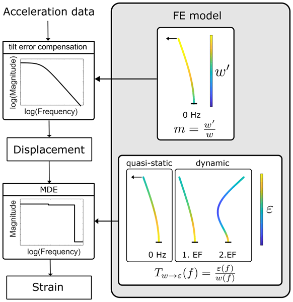
In this section, the novel approach for determining the quasi-static displacement response using acceleration data is presented. A flowchart of the relevant steps is given in Fig. 2. The two steps of the strain estimation, namely displacement estimation from accelerations using the combined tilt error compensation and double integration and the strain estimation from displacements using a transmissibility function based on the MDE, are described here.

2.1 Displacement estimation using DC-capable sensors
In previous work by Jonscher et al. (2025), it was found that the measured acceleration ameas is corrupted by gravitational acceleration g, resulting in a share of the measured acceleration, which is caused by g (ag(f)) due to the tilt of the sensor, as illustrated in Fig. 3. The actual acceleration of the structure in the inertial coordinate frame astr(f) can be expressed as
where c(f,m) is the correction factor accounting for the tilt error, and m is the tilt constant, which describes the ratio between the tilt w′ and the lateral displacement w in the quasi-static bending line, which is valid for small tilt angles in the quasi-static frequency range:
The tilt constant m is only determined for the static case as the tilt error is neglectable in the dynamic frequency range dominated by structural eigenmodes of current wind turbines. The correction factor c(f,m) has the amplitude response of a second-order high-pass filter with a cutoff frequency of gm but does not change the phase of the input signal. However, the resulting acceleration astr has to be integrated twice to get the displacements, necessitating the use of an additional high-pass filter (cf. Eq. 1) due to the unstable behaviour of the integration filter and thus losing information about the quasi-static motions. Furthermore, Jonscher et al. (2025) utilised integrated electronics piezo-electric (IEPE) accelerometers, which were able to measure at low frequencies due to the calibration performed according to Jonscher et al. (2022) but which could not measure the DC component. It was therefore not possible to estimate static displacements below 0.01 Hz in this way (Jonscher et al., 2025). Figure 4 shows the amplitude response of the integration filter and the tilt error compensation, the latter being particularly pronounced below the first eigenfrequency and for frequencies approaching 0 Hz. Additionally, utilising Eq. (4), it is also possible to calculate the frequency-dependent actual tilt of the tower:
This contribution focuses on the estimation of the static motion of the tower, which can be captured using DC-capable accelerometers. The static displacement can be expressed as
using Eq. (3).
Combining Eqs. (2) and (5), one finds that
In this expression for the tower displacement, the inertial accelerations are compensated. The resulting combined tilt error and integration filter (Eq. 6) shows a stable behaviour at 0 Hz, theoretically enabling the determination of static motions when DC-capable accelerometers are used. However, low-frequency noise in the measurement chain can still lead to a long-term drift, impeding the determination of static motions in practical applications. The frequency-dependent combined integration and tilt error correction resulting from Eq. (6) is shown in Fig. 4 together with the correction factor c(f,m) from Eq. (2) and the magnitude of the double integration filter.

Figure 3Schematic representation of the tilt error experienced by a deflected tower structure based on Jonscher et al. (2025).

Figure 4Integration filter, tilt error compensation filter, and proposed combined integration and tilt error filter. The influence of the tilt error is marginal above the first eigenfrequency (EF).
For the static case f=0 Hz the measured acceleration is solely due to the tilt error, which is assumed to be true in the entire quasi-static frequency band in the MDE approach by Toftekær et al. (2023). Equation (6) then simplifies to
which means that offset errors in the measured mean acceleration are directly propagated to the estimated tower displacement. To avoid such errors, either the sensor needs to be aligned precisely during the installation or the misalignment has to be compensated numerically by applying the rotation matrix R−1 to the measured acceleration.
The rotation matrix is defined such that the mean gravitational acceleration vector measured in the sensor frame is aligned with the negative y axis. The two Euler angles ϕ and ξ represent a rotation about the sensor x axis and z axis, respectively.
Measurement data for calm conditions with minimal movement of the tower are averaged to suppress measurement noise and obtain a raw mean gravitational vector . The Euler angles can be determined as
This approach does not allow for compensation of alignment errors in the yaw direction.
2.2 Strain estimation from displacements
The displacements estimated as described above serve as an input for the strain estimation. The focus of this contribution is strain estimation using displacements derived from a single accelerometer. If multiple sensors were available, several proven methods could be used for this step, such as the Kalman filters or the modal decomposition and expansion (MDE). The proposed method involves constructing a transmissibility function that maps displacements to strain based on the MDE, denoted by Tw→ε. Therefore, a brief explanation of the MDE, based on the work of Tarpø et al. (2020), is provided here. In MDE, the displacements or strains are usually obtained from multiple acceleration measurements and the structure's mode shapes. It is assumed that the system response in terms of displacements w can be represented in modal coordinates q(t) using the mode shape matrix: Φ
Equivalently, the system response in terms of strains ε is expressed using the strain mode shape matrix θ as
Since not all infinite modes can be preserved in this step, and high-frequency modes can safely be disregarded for wind turbine tower fatigue assessment, the mode shape matrix Φ and the strain mode shape matrix θ are truncated to only include a finite number of real modes. Consequently, the modal coordinates can be estimated as
from the displacement response wm, where [⋅]m denotes the measured locations. This modal decomposition is performed using a Moore–Penrose inverse of the mode shape matrix . The mode shape matrix is usually determined using a numerical model of the structure but can also be derived from an operational modal analysis, as shown by (Tarpø et al., 2020). Estimated quantities are marked with here. If the structural response is measured using accelerometers, the displacements have to be estimated before applying the MDE according to Sect. 2.1. In the modal expansion, the structural response is expanded in space using the estimated modal coordinates and mode shapes at the target locations Φt. These target locations are indicated by the index [⋅]t:
Similarly, the strains can be estimated by replacing the deflection mode shapes at the target locations with the strain mode shapes θt:
The number of modes considered in the MDE is limited by the number of input sensors and must therefore be truncated. Since the structural response of many structures, including offshore wind turbines, is usually dominated by just a few modes, this approach still yields adequate results even with only a few sensors (Baqersad et al., 2015). However, in this contribution, we focus on a sensor setup consisting of only one sensor position. Using the classical MDE, the vibration across the entire frequency band would then be projected onto the first eigenmode, leading to insufficiently accurate results. To overcome this limitation, the multi-band approach proposed by Iliopoulos et al. (2017) can be used in which the MDE is carried out independently for multiple frequency bands. The full-field strain εff can then be calculated as a superposition of the strains for each frequency band i=1…n:
Thus, different mode shapes and Ritz vectors can be used in each frequency band, depending on the dominant excitation. The approach also reduces the number of required sensors, as the number of modes per frequency band is now limited by the number of sensors rather than by the total number of considered modes. If only one acceleration sensor is used, the multi-band approach MDE simplifies to a frequency-dependent transmissibility function Tw→ε that takes into account the fact that unit displacements at different excitation frequencies result in different strains. Tw→ε is defined here as
where εt,FE(f) is the strain at the target location, and wm,FE(f) is the displacement at the measured location extracted from the finite-element (FE) model for different excitation frequencies f.

Figure 5Displacement-to-strain transmissibility function Tw→ε for different MDE approaches. All approaches are exact at the eigenfrequencies (EFs) but deviate from the continuous Tw→ε between the EFs and below the first EF.
In the simplest case, the considered frequency range is divided into n regions, where n is the number of considered modes. This would result in Tw→ε being a step function that is only correct at the eigenfrequencies and approximates the response at neighbouring frequencies, which is shown as an example in Fig. 5 for arbitrary locations of w and ε. This may be sufficient if the system's eigenfrequencies dominate the response. However, for wind turbines, this is not always the case as the excitation from wind and waves is usually below the first eigenfrequency. If a separate Ritz vector is considered for the quasi-static frequency range, the strain estimation can be improved, as shown by Iliopoulos et al. (2017). Tw→ε is then modified to capture the different Ritz vectors in the quasi-static frequency band, as shown in Fig. 5. However, depends on the position and type of excitation, which needs to be modelled. In theory, Tw→ε can be constructed for every excitation frequency, resulting in the example continuous graph shown in Fig. 5, which is calculated here exemplarily for 101 excitation frequencies in the shown frequency band. Unless this continuous Tw→ε is used, the strain estimation is only exact at support frequencies used for the construction of Tw→ε. However, for Tw→ε to be correct for all frequencies, the excitation type must be known at every frequency. As a simplification, only one additional Ritz vector – the static response to a horizontal force at the tower top representing the thrust load – is often used, e.g. in Iliopoulos et al. (2017) and Noppe et al. (2016).
To validate the proposed method, a laboratory-scale beam model was constructed. The steel beam shown in Fig. 6 has a total free length of 152.4 cm and a rectangular cross-section of 3 cm × 0.52 cm. It is equipped with DC-capable accelerometers of type PCB 3713B112G at the three measuring points (MPs) indicated in Fig. 6 as well as laser distance sensors of type Keyence IL-030 at MP3 and a laser distance sensor of type MEL M5/200 with a larger measurement range at the top level MP1. Additionally, the vertical strain is measured on both sides of the beam at the locations MP4 and MP5 using electrical strain gauges of type HBK 3/350ZE LY91 in a quarter-bridge configuration. To attach the strain gauges, the beam surface was sanded, reducing the cross-section in these areas to 3 cm × 0.5 cm. The acceleration, displacement and strain are measured with a sampling frequency of 600 Hz. The laser distance sensor at MP3 exhibits a time delay of approximately 0.01 s relative to the other sensors, which has been digitally compensated before performing any further data analysis. The measurement setup and the measuring point heights are documented in Table 1.

Figure 6Photo and schematic drawing of the experimental beam. The exact sensor positions are given in Table 1.
Table 1Heights of the measuring points on the experimental beam.

A displacement boundary condition is applied manually in the x direction at the top of the beam via a string connected to the beam with a magnet. The boundary condition consists of three distinctive parts indicated in Fig. 7. During the first 310 s (Part 1), stepped displacements are applied to demonstrate the proposed method's capability to estimate the quasi-static response. This part is followed by a free decay for about 85 s in Part 2. For the remaining 110 s (Part 3), a quasi-random displacement time series is applied to showcase the performance in a setting relevant for fatigue estimation.

Figure 7Measured displacement at MP1 located at the top of the beam structure. The three distinct parts of the time series are highlighted.
For the virtual sensing approach, an FE model of the beam is set up in Abaqus using Timoshenko beam elements. The masses of the accelerometers and the magnet used to apply the displacement boundary condition are modelled as inertial point masses. The sanded cross-section around the strain gauges was accounted for in the FE model by assuming a reduced cross-section in the region 30 mm above and below the strain gauge positions. In the FE model, the boundary condition at the base of the structure is updated to match the modal parameters of the first three bending modes in the x direction identified from the acceleration measurements during the free decay from t=310 s to t=395 s using operational modal analysis. The dynamic properties, especially the mode shapes, of the updated FE model are found to match those of the real structure for a rotational stiffness of krot=4.000 Nm rad−1. The considered eigenfrequencies and mode shapes of the updated model, as well as the measurement results for the real structure, are shown in Table 2. The mode shapes of the real structure are determined from the acceleration measurements using operational modal analysis and are herein compared to the mode shapes from the FE model using the modal assurance criterion (MAC). Even though a significant deviation in the eigenfrequencies is still observable, the mode shapes show good agreement with MAC values close to 1. Since mode shapes are the relevant modal parameter for the employed approach, the updating is considered sufficiently accurate for this application.
Table 2Comparison of the first three modes in the x direction of the laboratory beam (m) and the updated FE model (FE, u).

3.1 Displacement estimation results
The displacements at MP1 and MP3 were estimated as shown in Fig. 2 using the tilt constants m derived from the static bending line of the FE model, which was obtained by application of a horizontal unit force at the top of the beam. The tilt constants m and the amplitude behaviour of the resulting filters are shown in Fig. 8 for MP1, MP2 and MP3. As the tilt error is more pronounced at higher positions, m is also larger, and the combined tilt error compensation and integration filter has a smaller amplitude for higher measuring points, meaning a smaller share of the measured acceleration is in fact due to the structural acceleration. The measured accelerations have been corrected for rotational offset according to Eq. (10). All measured data have been low-pass-filtered using an infinite impulse response (IIR) filter with a cutoff frequency of 12 Hz, as the frequencies above 12 Hz do not significantly contribute to the structural response.

Figure 8Amplitude behaviour of the combined integration and tilt error filter for the accelerometer positions MP1, MP2 and MP3. The tilt constants m are given in rad m−1.
Two quality metrics commonly used in the literature for evaluating the performance of strain estimation methods are used here: the normalised root mean squared error (NRMSE) as used in Moynihan et al. (2024), Noppe et al. (2016) and Jonscher et al. (2025) and the evaluation via the error in the damage-equivalent strains (ΔDES) or displacements (ΔDED) used in Tarpø et al. (2020), Henkel et al. (2020), Fallais et al. (2024) and Henkel et al. (2021). The latter is used for evaluating Part 3, as it captures the fatigue-relevant characteristics of a time series. The ΔDED is defined here as
where DEDe and DEDm are the DED from the estimated and measured displacement time series, respectively. The DED is calculated from the ranges Δwi and number of cycles ni obtained from a rainflow counting of the time series according to the ASTM E 1049 standard (ASTM, 2017). The DED can then be calculated as
assuming a generic Wöhler (SN) curve with a fatigue exponent mSN=3 for Nref reference load cycles. Equivalently, for comparing strain time series, the deviation in the damage-equivalent strains (ΔDES) is introduced, calculated from the strain time series as input to the rainflow counting. Additionally, the NRMSE is used for evaluating Part 1, as it provides more reliable information for quasi-static loading with only a few cycles. It is defined here as
from the measured and estimated time series xm and xe, respectively, normalised with respect to the standard deviation of the measured time series.
The displacements estimated according to the proposed method are compared to the measured displacements in Fig. 9 for the accelerometer position MP1. The estimated displacements show good agreement with the measured displacement, as shown by the quality metrics in Table 3. Not only can the vibrations at the eigenfrequencies be estimated accurately, as can be seen from Zoom 2 in Fig. 9, where the first eigenfrequency dominates during the free decay, and the frequency spectra shown in Fig. 10, but the static and quasi-static displacements can also be captured accurately, as shown in Zoom 1 and Zoom 3 in Fig. 9, respectively, and the zoom into the frequency range from 0 to 0.3 Hz in the spectrum in Fig. 10. The absolute error shown in Fig. 11 is generally low, with errors below 0.1 mm for MP3 and errors below 0.2 mm for MP1. The laser displacement sensor at MP1, however, has a high noise level, as visible in Fig. 10, contributing to a share of the observed absolute error. The estimated displacement can be used as input for strain estimation.

Figure 9Displacement estimation at MP1 using the accelerometer at the respective level. Due to the similarity of the estimated and measured signals, some signals might not be visible in the plot.

Figure 10Spectrum of the displacement estimation at MP1 using the accelerometers at the respective level. Due to the similarity of the estimated and measured signals, some signals might not be visible in the plot.

Figure 11Absolute error of the displacement estimation at MP1 and MP3 using the accelerometers at the respective levels.
Table 3Quality metrics for the displacement estimation for two different sensor positions.

3.2 Strain estimation results
The strain is subsequently calculated from the displacement estimation obtained in the previous step, as shown in Fig. 2. For both MP4 and MP5, the strain is estimated three times using the accelerometers at MP1 to MP3 separately. The six transmissibility functions Tw→ε are constructed according to the MDE with an additional quasi-static frequency band. The frequency band limits are chosen as the centre of the supporting frequencies. The displacement and strain mode shapes and the Ritz vector for the quasi-static case are extracted from the FE model. A horizontal force at the beam top is assumed for calculating the Ritz vector in the quasi-static case. The resulting values of the step function Tw→ε for the strain estimation of MP4 and MP5 are given in Table 4.
Table 4Displacement-to-strain transmissibility function Tw→ε in m−1 for the strain estimation at MP4 and MP5 from displacements at MP1, MP2 and MP3 using a separate Ritz vector in the quasi-static frequency range.

The strain estimation results for MP4 are shown in Fig. 12. Corresponding to the evaluation carried out for the displacement estimation, the strain estimation is evaluated using the NRMSE for Part 1 and the ΔDES for Part 3 of the time series. The values resulting for NRMSE and ΔDES can be found in Table 5. The strain estimation consistently yields excellent results, with an absolute ΔDES below 1.7 %, except for the strain estimation at MP4 using acceleration at MP2, indicating that, for a known excitation, the proposed method enables reliable strain estimation using a single accelerometer. Furthermore, spatial extrapolation of the strain is possible, as accurate strain estimation can be achieved regardless of the input and output positions. The good agreement between the estimated and measured strains is achieved in both the quasi-static and dynamic frequency ranges, as can be concluded from the quality metrics in Table 5. The accuracy of the strain estimation in the quasi-static frequency range is evident in Zoom 1 and Zoom 3 in Fig. 12 and in the zoom into the frequency range from 0 to 0.3 Hz in the spectrum in Fig. 13. The strain estimation in the dynamic range is sufficiently accurate for determining fatigue damage close to the eigenfrequencies (cf. Zoom 2 in Figs. 12 and 13). However, between the first and second eigenfrequency, the estimations deviate from the measured strain. Since not much energy is contained in these frequencies, this can hardly be seen in the time domain representation of the strain but becomes visible in the spectrum in Fig. 13. This deviation is due to the approximation of the continuous Tw→ε as a step function. Therefore, frequencies below the band limit frequency are assigned to the lower frequency band, while higher frequencies are assumed to vibrate in the shape of the upper frequency band. This leads to the discontinuity in Tw→ε at the band limit frequencies, which is visible in the spectra and has also been observed by Noppe et al. (2016, 2018). This issue can be alleviated by using the continuous Tw→ε function, which does not possess this discontinuity. However, a continuous Tw→ε inflates strains at frequencies where the displacement shape has a nodal point, leading to a pole in the function Tw→ε, which is also undesirable.

Figure 12Strain estimation at MP4 using the accelerometers at MP1, MP2 and MP3. Due to the similarity of the estimated and measured signals, some signals might not be visible in the plot.

Figure 13Spectrum of the strain estimation at MP4 using the accelerometers at MP1, MP2 and MP3.
Table 5Quality metrics for the strain estimation for different acceleration sensor positions.

In the previous section, the proposed method is shown to yield accurate displacement and strain estimation results in a laboratory-scale experiment under controlled conditions. In this section, the proposed method is applied to measurements recorded during the operation of an offshore wind turbine. The goal is to showcase the method's performance in a realistic setting, where deviations in the in situ conditions from design assumptions are not known in detail. The considered offshore wind turbine is located in the German Bight in the North Sea with a water depth of approximately 24 m. The wind turbine is supported by a monopile foundation embedded in medium-dense sand. For confidentiality reasons, additional information about the construction cannot be disclosed. The tower is equipped with DC-capable accelerometers measuring in both horizontal directions at three positions: close to the tower top (TT), at the tower middle (TM) and close to the transition piece (TP). Furthermore, six strain gauges are installed close to the TP. The relative elevation normalised with respect to the hub height and the orientations of the installed sensors are summarised in Table 6, and an illustration of the wind turbine with the indicated sensor positions and orientations is given in Fig. 14. Both accelerations and strains were sampled at 25 Hz. The temperature-corrected measurement data recorded by the strain gauges are used to validate the strain estimation.
Two datasets using the same measurement setup have been evaluated here. The first dataset encompasses 9.5 h of continuous measurement. The second dataset encompasses 1 month of measurement data. The turbine operates under part-load conditions during the measurement period of dataset 1 except for approximately 20 min from 05:00 to 05:20 h, when the turbine is shut down. The minimum, maximum and mean values of some of the relevant SCADA data are given in Table 7 for both datasets to give an impression of the occurring environmental and operational conditions (EOCs), underlining the fact that the method is applied to data under varying EOCs.

Figure 14Schematic drawing of the sensor setup on the offshore wind turbine showing the sensor placement.
Table 6Relative elevations normalised with respect to the hub height and orientations of the sensors on the offshore wind turbine.

Table 7Statistical properties of selected EOCs during the measurement period.

An Abaqus FE model of the structure, consisting of Timoshenko beam elements, is set up based on the design assumptions. The rotor–nacelle assembly is modelled as a lumped mass, while the soil is modelled using 42 linear springs in the horizontal directions. The deviation in the eigenfrequencies is expressed as
The second-order modal assurance criterion (S2MAC) (D'Ambrogio and Fregolent, 2003) values of the first bending mode pair are presented in Table 8. By comparing the mode shapes with the S2MAC, the alignment uncertainty within the mode subspace is excluded, which can be significant for tower structures with closely spaced modes, as shown in Jonscher et al. (2023). The comparison of the modal parameters reveals a good agreement of the calculated first bending mode pair with the measurement data from the real structure.
Table 8Comparison of structure and the FE model: deviations in the eigenfrequencies and the mode shape assessed via the S2MAC.

4.1 Strain estimation results
All acceleration and strain time series were low-pass-filtered with a cutoff frequency of 2 Hz for evaluation and validation, respectively, therefore including the quasi-static frequency range, the first eigenmode, and frequencies dominated by the rotor excitation and the second eigenmode. This frequency range is chosen since it allows most of the fatigue-relevant vibrations to be captured. This is illustrated exemplarily for the investigated measured strain time series from dataset 1 in Table 9. A total of 99.5 % of the DES can already be captured by the quasi-static vibrations below 0.1 Hz alone for this time series. This share increases to more than 99 % when the first eigenfrequency is included (0–0.5 Hz). However, it should be noted that frequencies above 2 Hz, which are dominated by the rotor dynamics and higher tower eigenmodes, can have a larger influence on the fatigue loads in the support structure for other operational or environmental conditions, for example by increasing the strain amplitude during sudden events like shut-down or start-ups. Despite this, the cut-off frequency is chosen as 2 Hz, allowing the focus to be placed on the performance in the low-frequency range, in which strain estimation using accelerations only is typically challenging.
Table 9Share of damage-equivalent strain caused by for different frequency bands for the measured strain time series at TP at 35°.

The strains are estimated from the estimated displacement using the combined integration and tilt-error-compensation filter introduced in Sect. 2.1. The utilised tilt constants m and the resulting frequency-dependent amplification function were obtained in the same fashion as described in the previous section and are shown in Fig. 15. The strain time series are subsequently estimated using Tw→ε constructed using the parameters given in Table 10. It is assumed for this proof of concept that the dominant load in the quasi-static frequency range is the thrust load on the rotor. Therefore, as a simplification, only the thrust load is considered here. The values of Tw→ε in this frequency range are therefore determined from the static bending line resulting from a horizontal force applied to the top of the tower, regardless of the direction and operational condition. Furthermore, since the FE model is axisymmetric, any directional dependence of Tw→ε is neglected here. More complex load assumptions and a more detailed FE model with a detailed rotor and directional soil model would result in direction-dependent tilt constants m and transmissibility functions Tw→ε.

Figure 15Amplitude behaviour of the combined integration and tilt error filter for the three accelerometer positions TT, TM and TP. The tilt error constant m is given in rad m−1.
Table 10Displacement-to-strain transmissibility function Tw→ε in m−1 for the strain estimation at TP from the displacements at TT, TM and TP using a separate Ritz vector in the quasi-static frequency range.

For each strain gauge position, the strain has been estimated using the accelerometers at TT, TM and TP separately. The acceleration signals ameas,x and ameas,y have been rotated to match the orientation angle of the respective strain gauge θstrain before applying the proposed method using the transformation
The resulting strain time series exhibits a long-term drift, which has been removed by applying a second-order zero-phase high-pass filter with a cutoff frequency of 0.0001 Hz to both the measured and estimated strains. This drift is likely caused by measurement noise and is not inherent to the method formulation. However, for this measurement setup it limits the method's ability to estimate the DC component of the strain. The strain estimation is then evaluated using the quality metric ΔDES, as introduced in Sect. 3.1. The ΔDES for all input and output combinations is calculated using a generic SN curve with mSN=5 and Nref=107.
The resulting ΔDES values for dataset 1 are shown in Table 11 and range from −0.53 % to −10.33 %. This deviation is comparable to other published results in which deviations in the damage-equivalent strain of around 6.1 % (Iliopoulos et al., 2017) and 2 % to 18 % (Fallais et al., 2025) have been found. The high-pass-filtered results of the proposed method for strain estimation are shown as an example in Fig. 16 for the strain gauge position at 35° next to the 10 min mean values of the yaw angle and the wind speed in Fig. 17. The significant deviation during the first hour is due to the high-pass filter settling in. The long duration of the settling is caused by the low cutoff frequency; a higher cutoff frequency would reduce the error during the first hour.
The method accurately captures the general trends, i.e. the quasi-static frequency range and the structural response close to the first eigenfrequency, as shown in the spectrum in Fig. 18. The zoom in Fig. 18 further highlights the good agreement between the estimated and measured strains in the quasi-static frequency range, regardless of the accelerometer position used as input. The agreement in the quasi-static frequency range can also be observed in Zoom 1 in Fig. 16. In contrast, the spectrum reveals bad agreement for higher frequencies dominated by the rotor harmonics and higher eigenmodes, which do however have a negligible effect on the total DES for the investigated time series. The deviation for higher frequencies is likely caused by the rotor modelling as lumped mass, which has been shown to highly influence the second tower bending mode (Reinhardt et al., 2024) and leads to bad agreement between estimated and measured strain at frequencies above the first eigenfrequency (Pedersen et al., 2026). Furthermore, the method shows good agreement for the shutdown event around 05:00 LT, which is shown in detail in the same illustration. As shutdown events result in significant changes in strain, an accurate strain estimation is critical for fatigue estimation. Figure 19 shows the absolute error between the estimated and measured strains. This remaining error can be attributed to modelling uncertainties, EOC-dependent changes in the dominant loading and the measurement technology.

Figure 16Strain estimation at TP at 35° using the accelerometers at the TT, TM and TP. Due to the similarity of the estimated and measured signals, some signals might not be visible in the plot. The shutdown event is highlighted in grey.


Figure 18Spectrum of the strain estimation at TP at 35° using the accelerometers at the TT, TM and TP and a Hanning window of 30 000 samples. The zoom shows the spectrum in the low-frequency range. Due to the similarity of the estimated and measured signals, some signals might not be visible in the plot. For reasons of confidentiality, the frequencies cannot be disclosed.

Figure 19Error in the strain estimation at TP at 35° using the accelerometers at the TT, TM and TP. The shutdown event is highlighted in grey.

After having shown good accuracy for the short measurement period of dataset 1, the method has been applied to dataset 2 to assess the method's performance over a longer measurement period of 1 month under varying EOC. In contrast to the previous evaluation, the strain has been estimated for 10 min periods to allow for a yaw transformation using the available 10 min mean yaw position. To avoid the observed effects of the low-pass filtering, an additional 60 min was evaluated before and after the respective 10 min period and cut-off before calculating ΔDES. Both the estimated and measured strain time series have been band-pass-filtered between 0.1 mHz and 2 Hz. Figure 20 shows the results of the application of the strain estimation method to dataset 2 for the level TP in the fore–aft (FA) and side–side (SS) directions. Additionally, Fig. 20 shows the coefficient of determination R2 and the mean percentage error (MPE). The results show very good agreement in the FA and SS directions with only small deviations from a perfect fit, as indicated by R2≈1 and a MPE below 9 %. While both metrics indicate a slightly better estimate in the FA than in the SS direction, the observed difference in accuracy is minor. This indicates that the simplified load assumption of the thrust load being dominant regardless of the direction is sufficient for the investigated dataset for both the FA and SS directions. While the thrust load is certainly dominant in the FA direction under operation, due to yaw misalignment (Kragh et al., 2013), it appears to also be the dominant quasi-static load in the SS direction. Other loads acting on the tower like the rotor load eccentricity or the wave load do not distort the strain estimation in the investigated dataset. Furthermore in the SS direction, the quasi-static frequency range, where the load assumptions affect the estimation, is less relevant in the SS direction than in the FA direction, as a larger share of the fatigue-relevant vibration occurs at the first eigenfrequency.

Figure 20Scatterplot of the DES calculated from the estimated and measured strain time series in dataset 2 (1 month of measurement) at TP in the FA and SS directions using different acceleration sensors as input. Each point represents 10 min of measurements. The coefficient of determination R2 and the mean percentage error (MPE) in per cent are given.
The results of this study show that accounting for the tilt error in strain estimation on wind turbine support structures enables an accurate strain estimation using a single biaxial and DC-capable accelerometer. A key advantage of the presented approach is its ability to enable a cost-effective, low-maintenance load monitoring of wind turbine support structures, as only one biaxial DC-capable accelerometer and a beam model of the structure are required to estimate strains. Comparisons of both measured and estimated displacements and strains in a laboratory setting show excellent agreement, not only in the dynamic but also in the quasi-static frequency range, which is otherwise difficult to determine using only acceleration as input. Low deviations in the damage-equivalent strain promise a reliable estimation of fatigue life consumption throughout the entire structure. However, the approach necessitates a sufficiently accurate finite-element model and correct load assumptions. Similar results can be observed from the application of the approach to data from a full-scale offshore wind turbine. Due to a limited dataset, the method could only be validated for one position, for which a strain estimation accuracy comparable to other publications could be achieved. Even though the estimated damage-equivalent strains are larger than in the laboratory setting, deviations comparable to those achieved with other methods using more input data can be achieved.
The remaining deviation is likely due to uncertainties in finite-element modelling that arise because the underlying finite-element model is based on design data, neglecting manufacturing and construction deviations. Sensitive parameters, such as the soil stiffness distribution, can deviate significantly from the design assumption as they involve a high uncertainty. Moreover, any asymmetries in the mass and stiffness distributions throughout the wind turbine support structure are neglected in the modelling. Furthermore, the influence of varying EOCs is neglected in the calculation of the tilt constant m and the transmissibility function Tw→ε. Such variations can affect the static bending line and mode shapes and can occur due to temperature gradients, waves or changes in water level with the tide. Most EOC-dependent effects cannot be identified using the available dataset due to its short duration. Additionally, for this application, the rotor thrust is assumed to dominate the quasi-static response. However, a wind turbine experiences a variety of different loads in addition to the thrust load, caused for example by waves or the eccentricity of the rotor load. The dominant load varies with the direction and operational condition. While the thrust load is the dominant load in the FA direction during power production, it is less relevant in the SS direction. However, due to yaw misalignment, the thrust load is still present in the SS direction. Additional loads from the rotor eccentricity and the waves may become relevant in the SS direction under different EOCs but are neglected here. Furthermore, the amplitude and therefore composition of the different loads can vary with different operational conditions (Skafte et al., 2017; Toftekær et al., 2023). A more detailed modelling of the EOC-dependent excitation using multiple Ritz vectors and a continuous and direction-dependent transmissibility function might further improve the results and allow for an accurate strain estimation even for locations below the waterline. Finally, errors arise from uncertainties in sensor placement and from the measurement technology. Since biaxial accelerometers are used in the presented application to an offshore wind turbine, the misalignment correction according to Eq. (10) is not possible, and it cannot be guaranteed that the accelerometers are accurately aligned in the horizontal plane. The exact orientation of the accelerometers around the tower's circumference is also uncertain. Additionally, the measurement data are subject to measurement noise, necessitating the use of a high-pass filter for long measurement periods. Despite these limitations and simplifications, strain estimates with an accuracy comparable to state-of-the-art methods can already be achieved with fewer inputs.
This paper presents a novel approach to strain estimation on tower structures, particularly in the quasi-static frequency range, based on tilt error compensation using a single DC-capable accelerometer and a finite-element model. In the presented approach, displacements can be directly calculated from accelerations using parameters extracted from a finite-element model of the structure's static bending line and mode shapes, thereby combining tilt error compensation with double integration. The displacements are consequently transformed into strain using a transmissibility function based on modal decomposition and expansion. By combining tilt error compensation and double integration, the proposed method theoretically enables displacement and strain estimation down to 0 Hz using only one accelerometer. The approach requires a sufficiently accurate structural model and relies on load assumptions for quasi-static strain estimation. It was validated using a laboratory experiment and using measurement data from an operating offshore wind turbine. Excellent agreement between the estimated and measured displacements and strains was observed in the laboratory experiment, with deviations in the damage-equivalent strain of less than 5 % across all accelerometer measurement points. Both the quasi-static and dynamic responses could be captured, and a single accelerometer position was shown to be sufficient to accurately estimate strains at multiple locations. However, limited accuracy was observed close to frequency band limits, being responsible for the majority of the observed error. The remaining errors are likely due to modelling uncertainties, sensor positioning uncertainties and in the case of the strain estimation the noise level of the strain gauges. The strain estimation for the offshore wind turbine also yields accurate results but shows larger variations in the damage-equivalent strain, ranging from −0.5 % to −10.3 %, averaging out to a mean percentage error of less than 9 % in the validation using a month of data, which is comparable to other strain estimation methods. The larger deviation compared to the laboratory study is likely due to the more complex structure and environmental and operating conditions, as well as only considering the rotor thrust when estimating the quasi-static response. Due to measurement noise, a high-pass filter with a cutoff frequency of 0.0001 Hz was applied, which impeded the determination of static strains. The proposed method was shown to be an attractive alternative to established methods for strain estimation, as it relies on fewer sensors while yielding comparable accuracy, making it more cost-effective.
In future research, the proposed method should be validated against strain measurements on more target locations. The uncertainties in the strain estimation should be further investigated, particularly the influence of uncertain design parameters on the estimation accuracy. Additionally, future research should focus on improving the derivation of the transmissibility function that maps displacements to strains. This should also incorporate different Ritz vectors to better represent wave and rotor excitation under various operational conditions. Furthermore, it is of particular interest to find a sensor setup that minimises sensor cost while still enabling sufficiently accurate strain estimation, perhaps necessitating sensor fusion. The proposed method should be applied to wind turbine measurement data spanning longer time periods to identify damaging operational conditions, with the goal of developing strategies for lifetime-oriented operation of wind turbines, potentially necessitating a continuous model update to account for structural changes like scour development or marine growth. Lastly, future investigations should focus on extending the proposed method to monitor entire wind farms by applying population-based structural health monitoring techniques.
The associated source code containing the laboratory beam example (Sect. 3) is available as an open-access data publication within the Research Data Repository of Leibniz University Hanover: https://doi.org/10.25835/a8ikfjhy (Thurn et al., 2026).
The measurement data and finite-element model used in Sect. 3 are available as an open-access data publication within the Research Data Repository of Leibniz University Hanover: https://doi.org/10.25835/lyav246d (Thurn et al., 2025).
JT, CJ and BH devised the original idea for this research and did the formal analysis. JT and CJ designed the laboratory experiment. JT was responsible for carrying out the measurement campaign. GZ was responsible for data curation of the wind turbine data and further information about the wind turbine. JT carried out the analysis of the measurements. CJ and RR supervised the work. JT wrote the manuscript. All authors reviewed the manuscript.
At least one of the (co-)authors is a member of the editorial board of Wind Energy Science. The peer-review process was guided by an independent editor, and the authors also have no other competing interests to declare.
Publisher's note: Copernicus Publications remains neutral with regard to jurisdictional claims made in the text, published maps, institutional affiliations, or any other geographical representation in this paper. The authors bear the ultimate responsibility for providing appropriate place names. Views expressed in the text are those of the authors and do not necessarily reflect the views of the publisher.
We gratefully acknowledge RWE Offshore Wind GmbH for providing the data used in this study.
This research has been supported by the Volkswagen Foundation (grant no. ZN4468).
The publication of this article was funded by the open-access fund of Leibniz Universität Hannover.
This paper was edited by Yolanda Vidal and reviewed by three anonymous referees.
Advancing Standards Transforming Markets (ASTM): ASTM E1049-85: Standard Practices for Cycle Counting in Fatigue Analysis, ASTM International, West Conshohocken, PA, https://doi.org/10.1520/E1049-85R17, 2017. a
Augustyn, D., Smolka, U., Tygesen, U. T., Ulriksen, M. D., and Sørensen, J. D.: Data-driven model updating of an offshore wind jacket substructure, Appl. Ocean Res., 104, 102366, https://doi.org/10.1016/j.apor.2020.102366, 2020. a
Augustyn, D., Pedersen, R. R., Tygesen, U. T., Ulriksen, M. D., and Sørensen, J. D.: Feasibility of modal expansion for virtual sensing in offshore wind jacket substructures, Mar. Struct., 79, 103019, https://doi.org/10.1016/j.marstruc.2021.103019, 2021. a, b
Baqersad, J., Niezrecki, C., and Avitabile, P.: Full-field dynamic strain prediction on a wind turbine using displacements of optical targets measured by stereophotogrammetry, Mech. Syst. Signal Pr., 62–63, 284–295, https://doi.org/10.1016/j.ymssp.2015.03.021, 2015. a, b
Bilbao, J., Lourens, E.-M., Schulze, A., and Ziegler, L.: Virtual sensing in an onshore wind turbine tower using a Gaussian process latent force model, Data-Centric Engineering, 3, https://doi.org/10.1017/dce.2022.38, 2022. a, b, c
Boroschek, R. L. and Legrand, D.: Tilt Motion Effects on the Double-Time Integration of Linear Accelerometers: An Experimental Approach, B. Seismol. Soc. Am., 96, 2072–2089, https://doi.org/10.1785/0120050167, 2006. a
Branlard, E., Giardina, D., and Brown, C. S. D.: Augmented Kalman filter with a reduced mechanical model to estimate tower loads on a land-based wind turbine: a step towards digital-twin simulations, Wind Energ. Sci., 5, 1155–1167, https://doi.org/10.5194/wes-5-1155-2020, 2020. a
D'Ambrogio, W. and Fregolent, A.: Higher-order MAC for the correlation of close and multiple modes, Mech. Syst. Signal Pr., 599–610, https://doi.org/10.1006/mssp.2002.1468, 2003. a
DNV-GL: DNVGL-ST-0126: Support structures for wind turbines, DNV GL, Høvik: Det Norske Veritas, https://www.dnv.com/energy/standards-guidelines/dnv-st-0126-support-structures-for-wind-turbines/ (last access: 7 September 2026), 2016. a
Fallais, D., Sastre Jurado, C., Weijtjens, W., and Devriendt, C.: Validation of a model-based dual-band modal decomposition and expansion approach for fatigue monitoring of offshore wind turbine foundations, in: Proceedings of the 10th European workshop on structural health monitoring, e-Journal of Nondestructive Testing, 29, https://doi.org/10.58286/29660, 2024. a
Fallais, D., Sastre Jurado, C., Weijtjens, W., and Devriendt, C.: Long-term validation of a model-based virtual sensing method for fatigue monitoring of offshore wind turbine support structures: Comparing as-designed with state-of-the-art foundation models, Mar. Struct., 104, 103841, https://doi.org/10.1016/j.marstruc.2025.103841, 2025. a, b
Farrar, C. R. and Worden, K.: Structural health monitoring: a machine learning perspective, John Wiley & Sons, ISBN 1118443217, https://doi.org/10.1002/9781118443118, 2012. a
Graugaard-Jensen, J., Brincker, R., Hjelm, H. P., and Munch, K.: Modal based fatigue monitoring of steel structures, in: Structural Dynamics EURODYN 2005: Proceedings of 6th International Conference on Structural Dynamics, Paris, France, 4–7 september 2005, pp. 305–310, Millpress, https://vbn.aau.dk/ws/portalfiles/portal/12757225/Modal_Based_Fatigue_Monitoring_of_Steel_Structures (last access: 7 September 2026), 2005. a
Henkel, M., Häfele, J., Weijtjens, W., Devriendt, C., Gebhardt, C. G., and Rolfes, R.: Strain estimation for offshore wind turbines with jacket substructures using dual-band modal expansion, Mar. Struct., 71, 102731, https://doi.org/10.1016/j.marstruc.2020.102731, 2020. a, b
Henkel, M., Weijtjens, W., and Devriendt, C.: Fatigue Stress Estimation for Submerged and Sub-Soil Welds of Offshore Wind Turbines on Monopiles Using Modal Expansion, Energies, 14, 7576, https://doi.org/10.3390/en14227576, 2021. a
Hjelm, H. P., Brincker, R., Graugaard-Jensen, J., and Munch, K.: Determination of stress histories in structures by natural input modal analysis, in: Proceedings of 23rd Conference and Exposition on Structural Dynamics (IMACXXIII), Citeseer, 838–844, https://svibs.com/wp-content/uploads/2023/11/2005_2.pdf (last access: 7 September 2026), 2005. a
Iliopoulos, A., Weijtjens, W., Van Hemelrijck, D., and Devriendt, C.: Fatigue assessment of offshore wind turbines on monopile foundations using multi-band modal expansion, Wind Energy, 20, 1463–1479, https://doi.org/10.1002/we.2104, 2017. a, b, c, d, e, f, g, h
Jonscher, C., Hofmeister, B., Grießmann, T., and Rolfes, R.: Very low frequency IEPE accelerometer calibration and application to a wind energy structure, Wind Energ. Sci., 7, 1053–1067, https://doi.org/10.5194/wes-7-1053-2022, 2022. a
Jonscher, C., Liesecke, L., Penner, N., Hofmeister, B., Grießmann, T., and Rolfes, R.: Influence of system changes on closely spaced modes of a large-scale concrete tower for the application to structural health monitoring, Journal of Civil Structural Health Monitoring, 13, 1043–1060, https://doi.org/10.1007/s13349-023-00693-6, 2023. a
Jonscher, C., Helming, P., Märtins, D., Fischer, A., Bonilla, D., Hofmeister, B., Grießmann, T., and Rolfes, R.: Dynamic displacement measurement of a wind turbine tower using accelerometers: tilt error compensation and validation, Wind Energ. Sci., 10, 193–205, https://doi.org/10.5194/wes-10-193-2025, 2025. a, b, c, d, e, f, g, h
Kragh, K. A., Hansen, M. H., and Mikkelsen, T.: Precision and shortcomings of yaw error estimation using spinner-based light detection and ranging, Wind Energy, 16, 353–366, https://doi.org/10.1002/we.1492, 2013. a
Łuczak, S.: Guidelines for tilt measurements realized by MEMS accelerometers, Int. J. Precis. Eng. Man., 15, 489–496, https://doi.org/10.1007/s12541-014-0362-5, 2014. a
Maes, K., de Roeck, G., Lombaert, G., Iliopoulos, A., van Hemelrijck, D., Devriendt, C., and Guillaume, P.: Continuous strain prediction for fatigue assessment of an offshore wind turbine using Kalman filtering techniques, pp. 44–49, IEEE, ISBN 978-1-4799-8215-8, https://doi.org/10.1109/EESMS.2015.7175850, 2015. a, b
Maes, K., Iliopoulos, A., Weijtjens, W., Devriendt, C., and Lombaert, G.: Dynamic strain estimation for fatigue assessment of an offshore monopile wind turbine using filtering and modal expansion algorithms, Mech. Syst. Signal Pr., 76-77, 592–611, https://doi.org/10.1016/j.ymssp.2016.01.004, 2016. a, b, c
Moynihan, B., Tronci, E. M., Hughes, M. C., Moaveni, B., and Hines, E.: Virtual sensing via Gaussian Process for bending moment response prediction of an offshore wind turbine using SCADA data, Renewable Energy, 227, 120466, https://doi.org/10.1016/j.renene.2024.120466, 2024. a, b
Nabuco, B., Tarpø, M., Tygesen, U. T., Brincker, R., and Zhao, G.: Fatigue Stress Estimation of an Offshore Jacket Structure Based on Operational Modal Analysis, Meas. Sci. Technol., 2020, 7890247, https://doi.org/10.1155/2020/7890247, 2020. a
Natarajan, A., Dimitrov, N. K., William Peter, D. R., Bergami, L., Madsen, J., Olesen, N., Krogh, T., Nielsen, J., Sørensen, J. D., Pedersen, M., Ohlsen, G., Lauritsen, J. L., Daub, P., Steiniger, M., Jørgensen, E., Vives, X., Skriver, S., Simmons, G., Ahmadikordkheili, R., et al.: Demonstration of Requirements for Life Extension of Wind Turbines Beyond Their Design Life, no. E-0196 in DTU Wind Energy E, DTU Wind Energy, Denmark, ISBN 978-87-93549-64-7, https://backend.orbit.dtu.dk/ws/files/204904301/Final_Report_LifeWind_DTU.pdf (last access: 7 September 2026), 2020. a
Noppe, N., Iliopoulos, A., Weijtjens, W., and Devriendt, C.: Full load estimation of an offshore wind turbine based on SCADA and accelerometer data, J. Phys. Conf. Ser., 753, 072025, https://doi.org/10.1088/1742-6596/753/7/072025, 2016. a, b, c, d, e
Noppe, N., Tatsis, K., Chatzi, E., Devrient, C., and Weijtjens, W.: Fatigue stress estimation of offshore wind turbine using a Kalman filter in combination with accelerometers, in: Proceedings of International Conference on Noise and Vibration Engineering (ISMA 2018), International Conference on Uncertainty in Structural Dynamics (USD 2018), KU Leuven, Department of Mechanical Engineering, 4693–6701, https://past.isma-isaac.be/downloads/isma2018/proceedings/Contribution_674_proceeding_3.pdf (last access: 7 September 2026), 2018. a
Papadimitriou, C., Fritzen, C.-P., Kraemer, P., and Ntotsios, E.: Fatigue predictions in entire body of metallic structures from a limited number of vibration sensors using Kalman filtering, Structural Control and Health Monitoring, 18, 554–573, https://doi.org/10.1002/stc.395, 2011. a
Pedersen, M. G., Rinker, J. M., Alcover, I. F., and Høgsberg, J.: Performance of multi-band MDE-based virtual sensing for estimating lifetime fatigue damage equivalent loads for the IEA 15 MW reference wind turbine, Wind Energ. Sci., 11, 2053–2091, https://doi.org/10.5194/wes-11-2053-2026, 2026. a
Reinhardt, T., Sastre Jurado, C., Weijtjens, W., and Devriendt, C.: On the influence of rotor nacelle assembly modelling on the computed eigenfrequencies of offshore wind turbines, J. Phys. Conf. Ser., 2767, 052034, https://doi.org/10.1088/1742-6596/2767/5/052034, 2024. a
Sastre Jurado, C., Weijtjens, W., Stuyts, B., Winkler, K., Fallais, D., and Devriendt, C.: Benchmarking Measured Eigenfrequencies: A Case Study of a North Sea Offshore Wind Farm, in: International Conference on Offshore Mechanics and Arctic Engineering, vol. 87820, V05AT06A092, American Society of Mechanical Engineers, https://doi.org/10.1115/OMAE2024-125634, 2024. a
Skafte, A., Kristoffersen, J., Vestermark, J., Tygesen, U. T., and Brincker, R.: Experimental study of strain prediction on wave induced structures using modal decomposition and quasi static Ritz vectors, Eng. Struct., 136, 261–276, https://doi.org/10.1016/j.engstruct.2017.01.014, 2017. a, b
Tarpø, M.: Stress Estimation of Offshore Structures, PhD thesis, Aarhus University, https://doi.org/10.7146/aul.393, 2020. a, b, c
Tarpø, M., Nabuco, B., Georgakis, C., and Brincker, R.: Expansion of experimental mode shape from operational modal analysis and virtual sensing for fatigue analysis using the modal expansion method, International Journal Engineering StructuresEngineering Structures, 130, 105280, https://doi.org/10.1016/j.ijfatigue.2019.105280, 2020. a, b, c, d, e, f
Tarpø, M., Nabuco, B., Boroschek, R., and Brincker, R.: Tilt errors of translational accelerometers attached to dynamic systems with tilt motion caused by the system response, J. Sound Vib., 498, 115967, https://doi.org/10.1016/j.jsv.2021.115967, 2021. a
Tarpø, M., Amador, S., Katsanos, E., Skog, M., Gjødvad, J., and Brincker, R.: Data–driven virtual sensing and dynamic strain estimation for fatigue analysis of offshore wind turbine using principal component analysis, Wind Energy, 25, 505–516, https://doi.org/10.1002/we.2683, 2022. a
Tarpø, M., Ulriksen, M. D., Augustyn, D., Dollerup, N., Caglio, L., and Sørensen, J. D.: Full-field stress estimation of offshore structures using modal expansion and principal component analysis, J. Sound Vib., 618, 119295, https://doi.org/10.1016/j.jsv.2025.119295, 2025. a
Thurn, J., Jonscher, C., and Rolfes, R.: A benchmark structure for virtual sensing on tower structures, LUIS [data set], https://doi.org/10.25835/lyav246d, 2025. a
Thurn, J., Jonscher, C., and Hofmeister, B.: Example code for virtual sensing for strain estimation on tower structures, LUIS [code], https://doi.org/10.25835/a8ikfjhy, 2026. a
Toftekær, J. F., Vestermark, J. T., and Jepsen, M. S.: Uncertainty of Virtually Sensed Stress Ranges in Offshore Wind Support Structures, in: Volume 1: Offshore Technology, American Society of Mechanical Engineers, ISBN 978-0-7918-8683-0, https://doi.org/10.1115/OMAE2023-101045, 2023. a, b, c, d, e, f, g
Tsiapoki, S. and Colomer Segura, C.: Seven Years SHM of Offshore Wind Turbine Foundations: Review, Experiences and Outlook, e-Journal of Nondestructive Testing, 29, https://doi.org/10.58286/29681, 2024. a
WindEurope: European Offshore Wind Farms Map, https://windeurope.org/data/products/european-offshore-wind-farms-map-public/, last access: 18 September 2025. a
Ziegler, L. and Muskulus, M.: Fatigue reassessment for lifetime extension of offshore wind monopile substructures, J. Phys. Conf. Ser., 753, 092010, https://doi.org/10.1088/1742-6596/753/9/092010, 2016. a
Zou, J., Lourens, E.-M., and Cicirello, A.: Virtual sensing of subsoil strain response in monopile-based offshore wind turbines via Gaussian process latent force models, Mech. Syst. Signal Pr., 200, 110488, https://doi.org/10.1016/j.ymssp.2023.110488, 2023. a
- Abstract
- Introduction
- Strain estimation method
- Experimental validation using a laboratory beam model
- Application to an offshore wind turbine
- Benefits and limitations
- Summary and outlook
- Code availability
- Data availability
- Author contributions
- Competing interests
- Disclaimer
- Acknowledgements
- Financial support
- Review statement
- References
- Abstract
- Introduction
- Strain estimation method
- Experimental validation using a laboratory beam model
- Application to an offshore wind turbine
- Benefits and limitations
- Summary and outlook
- Code availability
- Data availability
- Author contributions
- Competing interests
- Disclaimer
- Acknowledgements
- Financial support
- Review statement
- References