
the Creative Commons Attribution 4.0 License.
the Creative Commons Attribution 4.0 License.
 | 14 Sep 2026
Control design for floating wind turbines: a novel feedback control structure

Peter Naaijen
Jan-Willem van Wingerden
The generator speed feedback control of onshore wind turbines, via the pitch controller to feather the blades, is well established, but employing the same controller gains with floating offshore wind turbines causes the turbines to become unstable. Such instability is attributed to the coupling between the nacelle fore-aft motion and the wind turbine controller, which makes the wind turbine negatively damped. The non-minimum phase zeros existing in the transfer function from the blade pitch to the generator speed impose a fundamental limitation on the closed-loop bandwidth, posing a challenge to the operation of the floating turbines. This paper gives an overview of the control strategies and their tuning techniques employed for floating wind turbines in the presence of the negative damping instability. It discusses the different available strategies. Moreover, we propose a new controller that can alleviate the adverse effects of the negative damping while preserving the standard proportional-integral control structure. Contrary to the multi-input, multi-output controllers that have been proposed, the proposed controller is more robust as it does not require additional signals of the floating platform, which often makes controllers sensitive to unmodelled dynamics. The controller is compared against the previously proposed controllers using the non-linear simulation tool OpenFAST. The proposed controller excels in regulating generator speed, surpassing other controllers in performance. Additionally, it effectively mitigates the platform pitch in addition to the tower and blade loads. However, achieving a balance between power quality, actuator usage, and structural loading presents inherent trade-offs that need to be carefully addressed.
- Article
(6903 KB) - Full-text XML
- BibTeX
- EndNote


Wind energy is essential to meeting the decarbonisation objectives of the European Union (EU) energy system. Consequently, wind energy is expected to heavily contribute to the EU renewable energy targets, with wind energy already covering 19 % of the EU's electricity demand in 2024. This has seen the EU revising the renewable energy directive, which lays down a minimum target of 42.5 % share of renewables by 2030, with the aspiration of reaching 45 %. This is 10.5 % higher than the initial 32 % target. Subsequently, the EU could fulfil its ambition of becoming climate neutral by 2050 (European Commission, 2023).
Offshore wind represents a great asset in this regard, as it benefits from higher, more-consistent speeds than onshore alternatives. Floating offshore wind turbines (FOWTs) further extend this potential by enabling deployment in deep-water basins, such as the Mediterranean and Atlantic, where bottom-fixed turbines are unfeasible. However, FOWTs face harsher environments; unlike onshore systems, they are subjected to coupled wind and wave disturbances. These additional hydrodynamic loads, compounded by wind turbulence, significantly increase structural fatigue (Saenz-Aguirre et al., 2022).
The main challenge facing the further deployment of FOWTs is their high levelised cost of energy (LCOE). While modifications to their aerodynamic, hydrodynamic and structural design are applied to bring the LCOE down, the control system should not be overlooked (Starink et al., 2025; van den Berg et al., 2026). Developing new control architectures can contribute to reducing the LCOE. Another approach is control co-design (Pao et al., 2024), which has proven to be highly effective.
From a control perspective, FOWTs present additional complexities compared to onshore turbines. The dynamics introduced by the floating platform make control more challenging. A notable concern is the negative damping effect (Nielsen et al., 2006), as applying a fixed-bottom controller to a floating wind turbine can significantly amplify the system’s dynamic response, leading to large peak-to-peak oscillations and thus compromising both performance and structural safety. The simplest way to avoid closed-loop instability without modifying the conventional baseline controller structure is to detune the control gains such that the closed-loop response of the generator speed mode in isolation has a natural frequency below the platform pitch resonant frequency (Larsen and Hanson, 2007; Jonkman, 2008). However, this leads to a degradation in the reference tracking performance of the blade pitch controller as its ability to effectively respond to disturbances becomes restricted (Yu et al., 2018; Lemmer et al., 2020). Maintaining global detuning across all wind speeds sacrifices higher control bandwidths at higher wind speeds that do not suffer from this instability. Accordingly, it is reasonable to schedule the detuning at each wind speed separately (Yu et al., 2018, 2020; Lemmer et al., 2020; Stockhouse et al., 2024b).
Other methods explored in the literature involve incorporating extra feedback loops to counteract the instability arising from rotor–platform interactions. By utilising nacelle fore-aft velocity as feedback to adjust the existing baseline controller actuators, blade pitch (Jonkman, 2008; van der Veen et al., 2012; Fleming et al., 2014; Capaldo and Mella, 2023) and generator torque (Fischer, 2013; Fischer and Loepelmann, 2016) control inputs showed that performance improvements could be achieved without the need for additional actuators. Systems with more than one actuating control input and more than one sensor output may be considered as multivariable systems or multi-input, multi-output (MIMO) systems. The control objective for multivariable systems is to obtain a desirable behaviour of several output variables by simultaneously manipulating several input channels. A FOWT is a MIMO system. To evaluate such a system, MIMO transfer function matrix is needed. FOWT control strategies often utilise decoupled feedback loops, where each is tuned independently for a specific output (Fleming et al., 2012). Although this simplifies the multivariable design into a series of single-loop controllers, it neglects the inherent dynamic coupling of MIMO systems. Consequently, adjustments in one loop can induce undesirable interactions in others, necessitating a control approach that accounts for the coupling simultaneously. It was demonstrated that improved performance could be achieved when optimally tuning all the control loops collectively, accounting for the cross-coupling within the MIMO feedback structure rather than tuning each control loop independently (Stockhouse et al., 2024b). Modern multivariable control methodologies employing state-feedback architectures, including linear quadratic regulator (LQR) (Namik et al., 2008) and ℋ∞ control (De Corcuera et al., 2012; Hegazy et al., 2023a) demonstrate systematic efficacy in achieving specified stability and performance envelopes for complex dynamical systems (Skogestad and Postlethwaite, 2005).
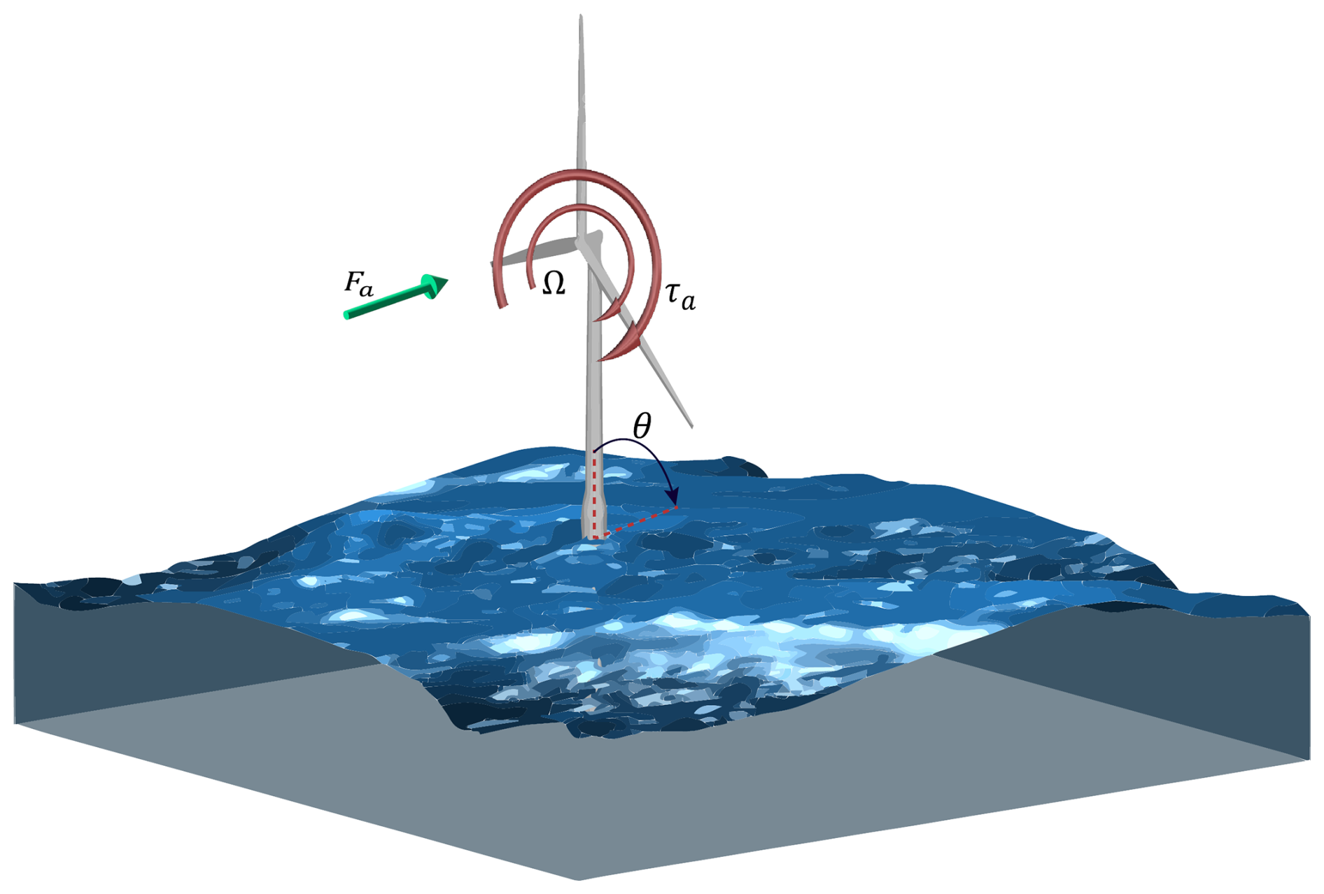
Figure 1Schematic of the FOWT depicting the generator speed Ω and the platform pitch θ, degrees of freedom (DOFs) of the simple control model together with the external forces, namely the aerodynamic thrust Fa, and torque τa, as expressed in Eq. (14).
The majority of control architectures designed to mitigate negative damping instability rely on auxiliary sensors to measure tower-top or platform acceleration in the fore-aft direction. Only recently, Hegazy et al. (2023a) demonstrated the feasibility of eliminating these additional sensing requirements, answering a proof-of-concept question: “Could a control structure relying exclusively on generator speed measurement overcome the bandwidth limitation imposed by the RHPZs in FOWTs? If yes, what form would such a structure take?” These questions were answered in a linear, frequency-domain setting only.
Keeping the proof-of-concept result in mind, the main contribution of this paper is to properly introduce the novel control structure that maintains robust performance without the need for supplementary sensors and to reduce it to an equivalent single-loop structure compatible with standard industrial proportional-integral (PI) tuning practice. We also revisit existing control strategies and equip them with a multi-objective optimisation-based tuning methodology, balancing stability margin, bandwidth, and control effort. The novel controller is further evaluated through non-linear, time-domain simulations under turbulent wind and irregular waves, alongside these alternative control strategies, revealing performance trade-offs. Collectively, these contributions establish a robust framework for mitigating negative damping while simultaneously reducing auxiliary sensing requirements in FOWTs.
This paper is structured as follows: Sect. 2 outlines the fundamental principles of FOWT closed-loop control and the origin of the negative damping phenomenon. Section 3 characterises existing control strategies to establish a baseline for comparison, before detailing our proposed control architecture. In Sect. 4, the controllers are evaluated by simulating the closed-loop system using the non-linear aero-servo-hydro-elastic tool OpenFAST (NREL, 2025a).
In this section, we start by introducing the dynamic model of a conventional fixed-bottom wind turbine. Afterwards, we go on to explain the process of closing the loop with the baseline controller and the tuning methodology of the controller gains. Once this is established, we move on to the FOWTs where we introduce the additional dynamics for the floating platform to form a representative dynamic model of a FOWT to conduct further analysis on the complexities that arise when controlling FOWTs.
Conventional wind turbine dynamics are excited by the imbalance between the aerodynamic torque and the generator torque, which drives the generator speed, and thus a simplified wind turbine model is described as
where Jr (kg m−2) is the rotor drivetrain inertia, Ω (rad s−1) is the generator speed with the dot notation indicating the time derivative, τa (N m−1) is the aerodynamic torque, Ngb (–) is the gearbox ratio, and τg (N m−1) is the generator torque. The aerodynamic torque is modelled by a non-linear function:
with ρ (kg m−3) as the air density; R (m) being the rotor radius, Cp(λ,β) the power coefficient, which depends on the blade pitch angle β (rad) and the tip-speed ratio ; and v (m s−1) the wind speed normal to the rotor plane. At steady state, the non-linear wind turbine dynamics in Eq. (1) can be linearised using first-order Taylor series expansion around an equilibrium point as
where δ denotes state perturbation, and the partial derivatives of τa with respect to its independent variables are known as the aerodynamic sensitivities.
In practice, wind turbines are regulated with a generator speed controller, as at below-rated wind speeds, the controller is seeking to maximise the extracted power by keeping the collective blade pitch angle β constant while varying the generator torque τg as a function of the square of the generator speed Ω as follows (Bossanyi, 2000):
with being the generator-torque constant. The variable Cp,max is the maximum power coefficient achieved at the optimal tip-speed ratio (TSR) λopt and at a specific constant blade pitch angle known as fine blade pitch angle. It is fair to mention that the controller in Eq. (4) assumes a constant kg throughout the wind turbine's lifetime. In reality, this is not the case, as it is influenced by modelling inaccuracies and assumption errors. To address this limitation, the TSR tracking controller has proven to be more effective and is widely adopted in the wind energy industry (Abbas et al., 2022; Brandetti et al., 2023).
At above-rated wind speeds (referred to as Region 3), a conventional wind turbine controller relies on the blade pitch to regulate the generator speed to its rated value Ωrat, while keeping the generator torque constant at its rated value (Bossanyi, 2000). As a result, generator power fluctuations are directly proportional to the oscillations occurring in the generator speed . The collective blade pitch controller regulates the generator speed about its steady-state value according to the following feedback control law (Jonkman et al., 2009; Abbas et al., 2022):
where kp and ki are the proportional and integral controller gains, respectively. To reach a description of the gains, the azimuth angle ψ is introduced as in Eqs. (3) and (5). By combining both equations and focusing on the generator speed terms, we derive a closed-loop system. When rewritten in the standard form of a second-order mass-spring-damper system, it becomes (Jonkman et al., 2009; Abbas et al., 2022)
Equation (3) represents the closed-loop system of the wind turbine in the above-rated region. Therefore, only the terms containing ψ and its derivatives are considered (Jonkman et al., 2009). The remaining terms are irrelevant to the control problem and therefore do not appear in Eq. (6). Accordingly, we can parameterise the PI blade pitch controller gains (Abbas et al., 2022):
Given a desired natural frequency ωc and damping ratio ζc, the PI controller gains can be computed (Åström and Murray, 2021; Abbas et al., 2022). By defining the ωc and ζc of the generator speed response, the dynamic response of the rotor to wind speed variations can be altered. The value of ωc defines the bandwidth of the feedback controller. Typically, the controller bandwidth is chosen below the lowest structural natural frequency of the system to avoid interaction with lightly damped modes, leading to instability. The bandwidth should not include the right-half-plane zeros (RHPZs) existing in the wind turbine system as Leithead and Dominguez (2006) reported. As shown in Eqs. (7) and (8), their controller gains depend on the aerodynamic sensitivities, which significantly vary across operating points. As a result, the controller gains are scheduled at each operating point and modified during operation as the wind speed changes to maintain consistent closed-loop transient behaviour using a linear controller.
The main challenge associated with the control of FOWTs within Region 3 concerns their fore-aft motion (Larsen and Hanson, 2007; Jonkman, 2008; van der Veen et al., 2012; Fischer, 2013). Therefore, it is critical to include floating platform dynamics in the control design model.
2.1 Floating wind turbine model
The main problem associated with the control of floating wind turbines concerns the pitch stability in full load (van der Veen et al., 2012; Larsen and Hanson, 2007; Jonkman, 2008; Fischer, 2013). The effect of varying wind speed on the steady-state thrust in the above-rated region has to be considered in order to understand this problem. The above-rated portion of the steady-state thrust curve, shown in Fig. 2, is defined as the thrust force required at a given wind speed to produce rated power at rated generator speed (van der Veen et al., 2012). The steady-state blade pitch angle varies along the operating curve to limit the aerodynamic torque and reduce the oscillation in the power production. The generator torque is kept constant instead of constant power as this strategy limits the generator speed variations and, hence, reduces drivetrain loads and pitch activity (Larsen and Hanson, 2007).
To form a FOWT mathematical model, the generic 1-DOF model of the wind turbine in Eq. (3) is combined with the floating platform dynamics. For the sake of explaining the negative damping problem analytically, only a 2-DOF FOWT model capturing the critical dynamics is used, where the platform pitch DOF is primarily considered to characterise platform dynamics, as the negative damping instability is most pronounced at the platform pitch eigenfrequency, where there is no damping from the mooring and very little hydrodynamic damping leading to negative damping if the pitch control is fast (Larsen and Hanson, 2007; Jonkman, 2008). However, to preserve key dynamic couplings, the control model used for the control design must include additional modes that capture the most significant system dynamics, namely the platform's surge and heave, and the tower first fore-aft bending (Lemmer et al., 2020); otherwise, some interactions within the system may be overlooked (Yu et al., 2020). The non-relevant DOFs are neglected to avoid accounting for extra states, which would increase the complexity. For this analysis, the NREL 5 MW reference wind turbine (RWT) (Jonkman et al., 2009) is mounted on top of the OC3 spar floater (Jonkman, 2010). This analysis was performed in Stockhouse et al. (2024b), Stockhouse and Pao (2024), and Stockhouse et al. (2024a) for different FOWT systems.
Thus, the rigid floating platform pitch motion in still water, affected by the aerodynamic thrust force only without any wave-induced forces, can be modelled as a second-order mass-spring-damper system:
where θ is the platform pitch angle, is the platform pitch rotational velocity, is the platform pitch rotational acceleration, Ip is the total mass moment of inertia about the platform pitch axis (comprising the structural inertia and the added mass associated with hydrodynamic radiation), C is the damping coefficient, and K includes the hydrostatic and the mooring stiffnesses. Within the analytical 2D model, the frequency-dependent radiation memory effects are disregarded by assuming a constant added mass and omitting radiation damping, as it is insignificant compared to viscous damping in FOWT platforms (Lemmer et al., 2016, 2020). Meanwhile, for the control model used for controller synthesis, a parametric radiation model is used (Perez and Fossen, 2009; Fontanella et al., 2020). However, for the time-domain simulations, the convolution integral (Cummins, 1961) is incorporated to account for the frequency-dependent coefficients. The variable Fa is the aerodynamic rotor thrust force, which causes a pitching moment on the platform through the hub height lh as a lever arm. The aerodynamic thrust force is a non-linear function is expressed by
where v is the rotor-effective wind speed and Ct is the thrust coefficient function in λ and β. The platform pitch motion influences the dynamics as it induces a relative wind speed at the rotor apart from the inflow wind speed v∞. Thus, the rotor-effective wind speed v is
Similar to Eq. (3), while considering Eq. (11), the non-linear platform dynamics can be linearised around an equilibrium point as
In a standard second-order form, by considering only the coefficients corresponding to the platform pitch motion, Eq. (12) can be rewritten as
with ωp and ζp being the natural frequency and the damping ratio of the floating platform in the pitch DOF, respectively.
The coupled dynamics of the wind turbine in Eq. (3) and the floating platform in Eq. (12) form a third-order system, which is represented in state-space form of , with a state vector and control input vector as
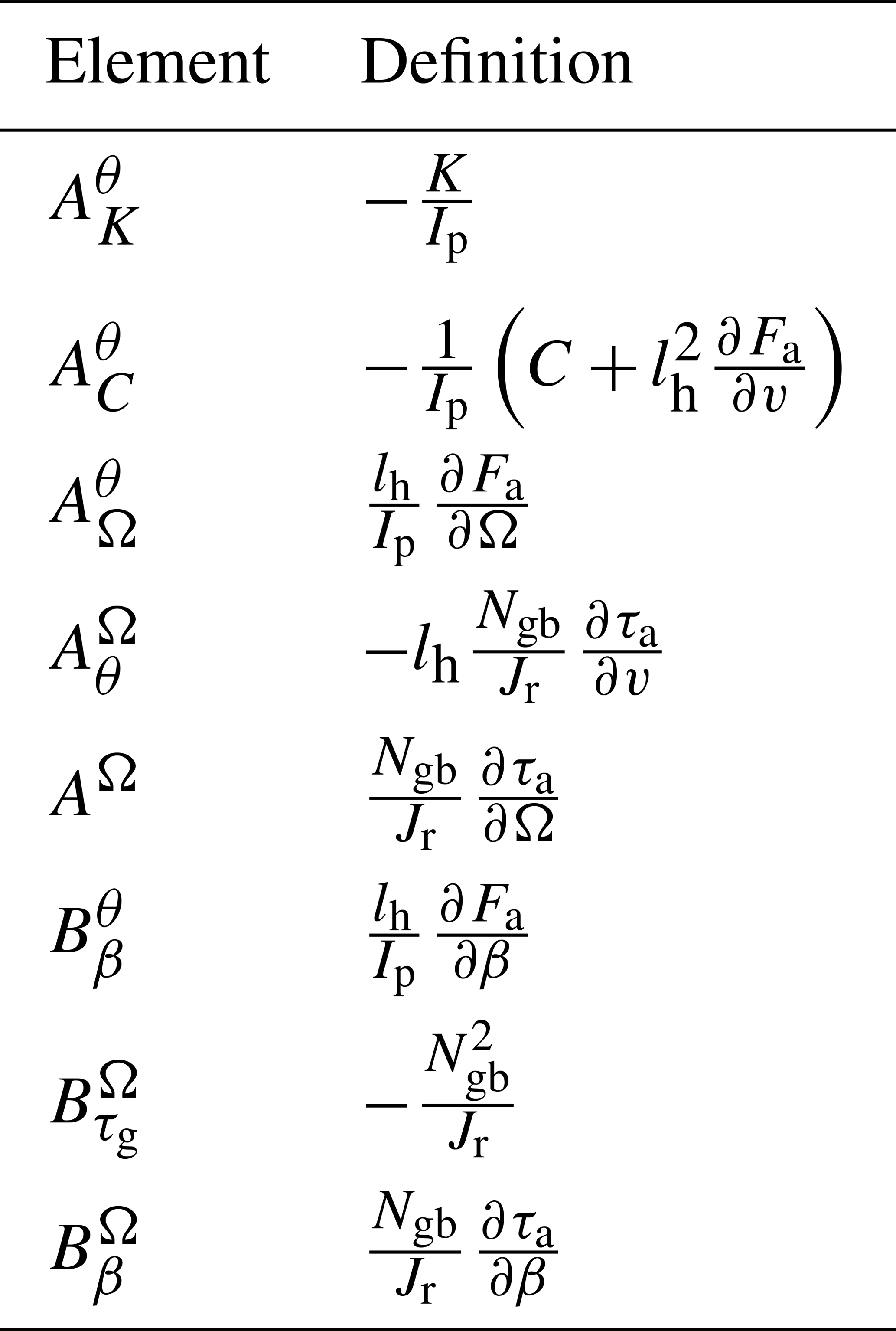
where the individual elements of the system matrix A and the input matrix B are defined in Table 1. The output vector , with the output matrix C and the feed-through matrix D, is defined according to the available system measurements, which is typically a subset of the states in the state vector x. In this paper, the output vector is chosen as and thus obtained for the state-space model in Eq. (14) as
Table 1The elements of the system matrices A and B (Stockhouse et al., 2024a, b).
Now with such a linear state-space model, we can view the problem analytically with a pole-zero plot, shown in Fig. 3, of the transfer function (TF) GΩ,β, mapping the collective pitch β to generator speed Ω, describing how generator speed (controlled variable) responds to a variation in blade collective pitch angle (control input). First, let us look at the analytical description of GΩ,β. This requires transferring to the frequency domain, which can be attained by applying , with s being the Laplace variable and I being the identity matrix. As a result, we get a MIMO transfer function matrix G(s)=Guy(s), mapping the input vector u to the output vector y. The transfer function matrix G(s) is composed of single-input single-output (SISO) TFs , mapping each input ui(s) to each output yi(s):
For the feedback control of FOWTs in Region 3, the control objective is to reduce the generator speed oscillations using the blade pitch action. Consequently, the TF GΩ,β, mapping the blade pitch angle to the generator speed in Eq. (16), is of the main interest:
where all the gradients vary with the operating point. To determine the zeros of GΩ,β, its numerator polynomial is set to zero, and the resulting equation is solved for s using the quadratic formula. Upon algebraic manipulation, it becomes evident that RHPZs, indicating non-minimum phase behaviour, emerge under the following condition (Fischer, 2013):
Equation (18) highlights the fact that the emergence of non-minimum phase behaviour, driven by the presence of RHPZs, is closely tied to the aerodynamic damping coefficient (μaero), which is influenced by aerodynamic gradients. This coefficient varies with the operating conditions and tends to be particularly low near the rated wind speed, as will be demonstrated in the following analysis.
Figure 2 illustrates the relationship between the steady-state aerodynamic thrust force (Fa) and the rotor-effective wind speed (v) for the above-rated operation of the NREL 5 MW reference wind turbine (Jonkman et al., 2009) installed on the OC3 spar floating platform (Jonkman, 2010). In a closed-loop FOWT system at steady state, the gradient is positive below-rated wind speed, meaning the thrust force increases as wind speed rises. However, beyond the rated wind speed, this gradient becomes negative, as shown in Fig. 2. This behaviour results from the pitch-to-feather control strategy, which reduces aerodynamic loads in the above-rated region. As a consequence, the aerodynamic damping is positive at below-rated wind speeds but turns negative at above-rated wind speeds. As Fa begins with a positive slope (μaero>0) in Region 2, where Fa keeps increasing until reaching its maximum at the rated wind speed where μaero=0. Once Region 3 is reached, Fa starts decreasing with a significantly steep negative slope (μaero<0). The steeper this decline, the lower the aerodynamic damping, with its minimum occurring just beyond the rated wind speed. As wind speed continues to increase, the slope gradually becomes less steep, indicating a partial recovery of aerodynamic damping.
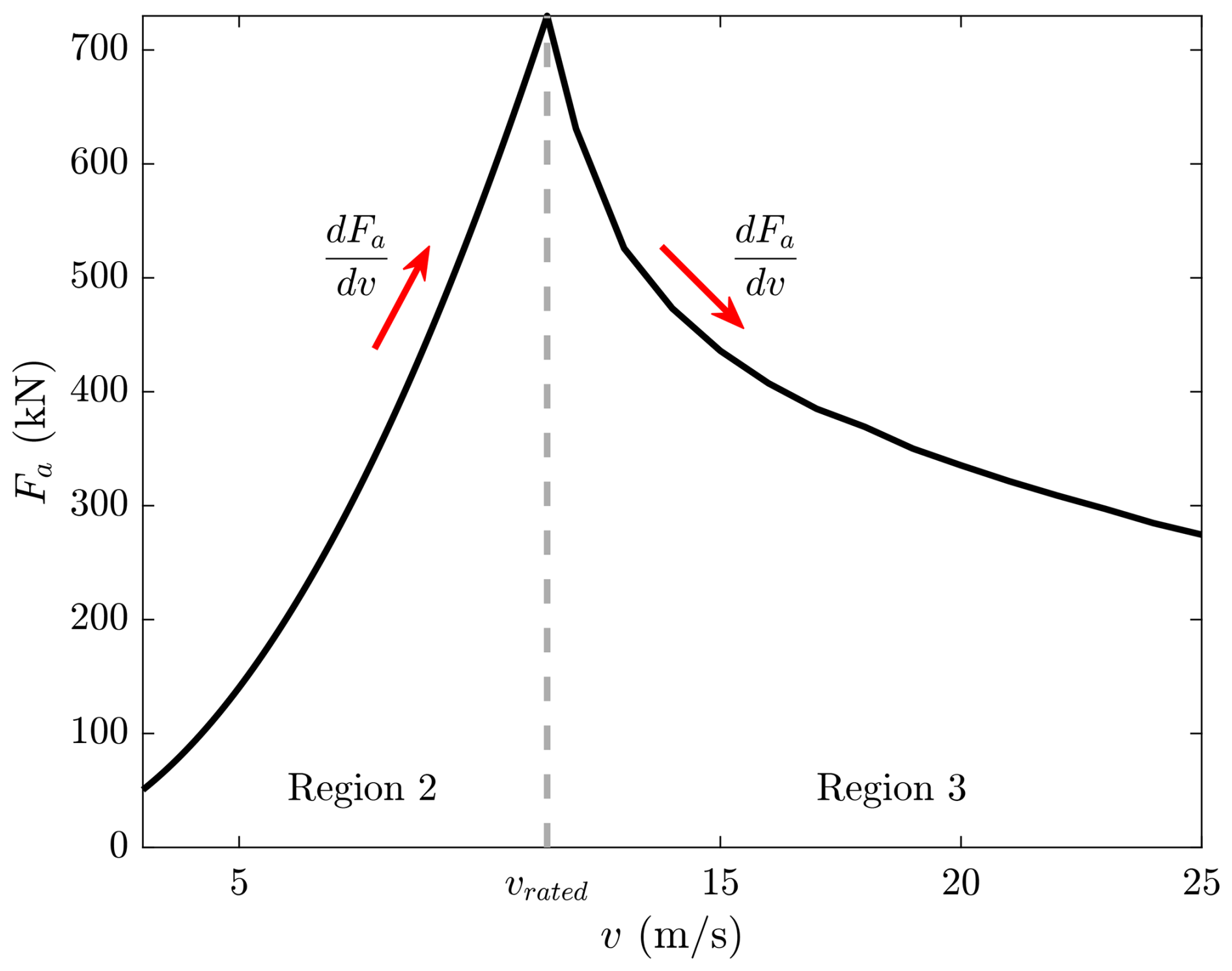
Figure 2Steady-state values of rotor thrust force Fa as a function of the effective rotor wind speed v for the NREL 5 MW baseline wind turbine on the OC3 spar floating platform.
The root cause of this behaviour is the negative total derivative of thrust force with respect to above-rated wind speeds (Fischer, 2013) as in Region 3; the rotor speed (Ωr) is at its constant rated value, while the aerodynamic torque (τa) varies. The objective is to achieve stable power production (P) with fewer variations such that its total differential diminishes (van der Veen et al., 2012):
and from Eq. (19), the total differential of the blade-pitch angle is
Similar to dτa in Eq. (19), the total differential of Fa is
Combining Eqs. (20) and (21), the total derivative of the aerodynamic thrust with respect to the wind speed, yielded from the variation of blade pitch to maintain rated power, is
Equation (22) demonstrates why Fa has a negative gradient as wind speed increases, a condition that is necessarily true for all conventional pitch-to-feather wind turbines (van der Veen et al., 2012). Burton et al. (2021) explain that as the wind increases above-rated, the pitch angle increases to maintain constant generator torque, but the aerodynamic thrust and torque decrease, indicating that the gradients and are negative. This allows the downwind fore-aft motion to decrease, which leads to an upwind fore-aft motion, causing the relative wind speed seen by the rotor to increase. Consequently, the aerodynamic torque increases further, causing more pitch action (Jonkman, 2008; van der Veen et al., 2012). Consequently, the gradient is positive. Therefore, after considering the signs of all the gradients in Eq. (22), it becomes clear why in the above-rated operation.
After obtaining GΩ,β from G(s) in Eq. (16), the pole-zero map of GΩ,β, which maps the blade collective pitch β to the generator speed Ω (describing how the generator speed responds to a variation in blade pitch angle), is shown in Fig. 3.
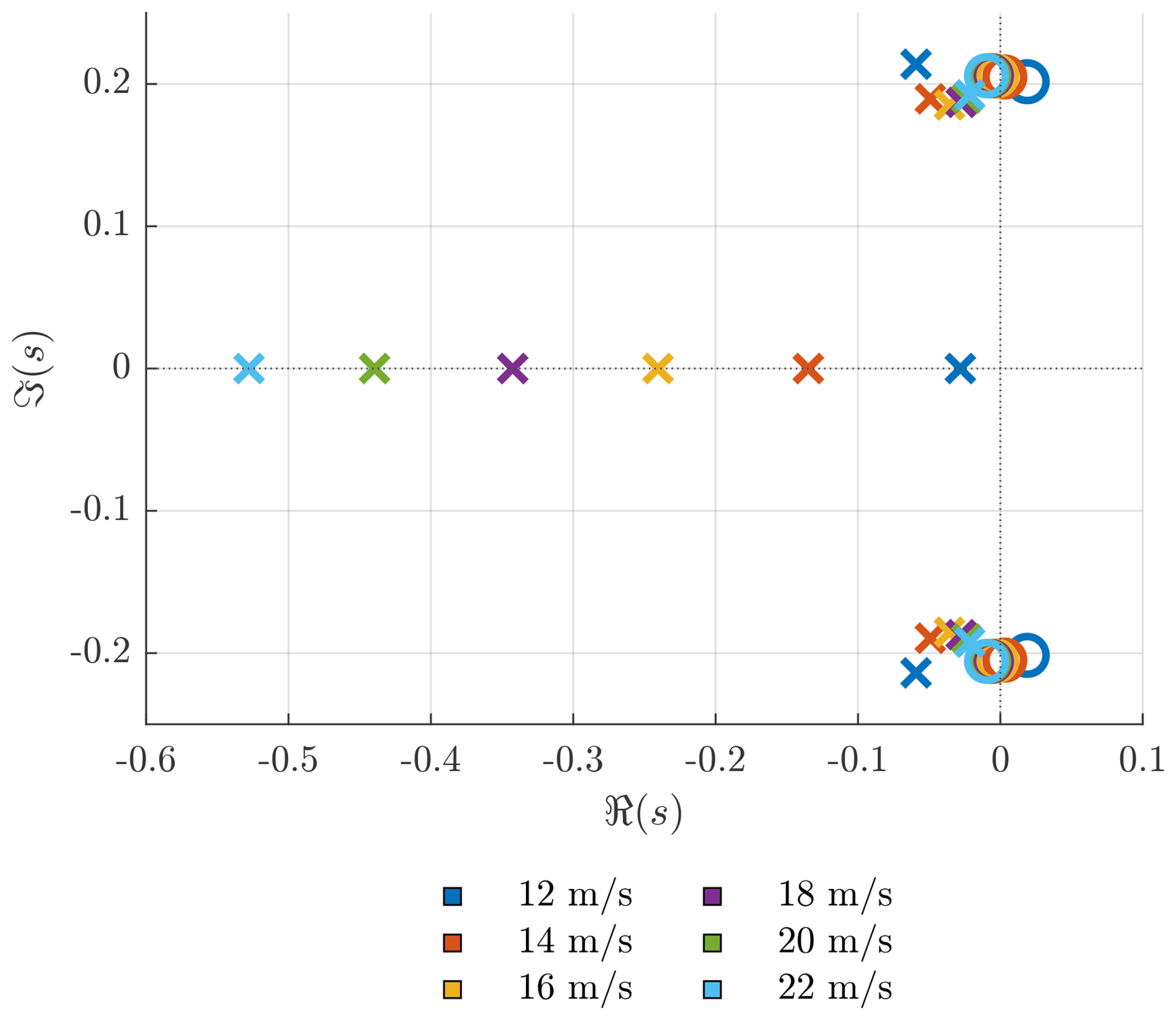
Figure 3Pole-zero map of the TF from blade collective pitch to rotor speed GΩ,β at different operating points. Poles and zeros are denoted by × and ∘, respectively.
Figure 3 shows that the TF GΩ,β consists of a complex pole pair, corresponding to the platform rigid-body pitch mode, and a real pole, associated with the drivetrain mode. Additionally, a complex pair of RHPZ appears at a frequency close to that of the platform pitch mode, indicating that the RHPZs condition in Eq. (18) is satisfied. The poles in the platform pitch mode of the open-loop transfer function GΩ,β correspond to the pitch-free decay damping ratio ζp and natural frequency (eigenfrequency) ωp. It can be seen in Fig. 3 that the open-loop system is originally stable because of the sufficient hydrodynamic damping (Yu et al., 2018) since all the poles are in the left-half-plane (LHP).
However, the closed-loop poles of a system would migrate from the open-loop poles location towards the open-loop zeros as the feedback gain increases (van der Veen et al., 2012). Hence, according to Fig. 3, the platform pitch mode becomes less damped, while the generator speed tracking improves. In the case where the zeros are in the right-half-plane, which for the model visualised in Fig. 3 is true only for the platform pitch zeros, the frequencies provide bandwidth limits on GΩ,β loop.
2.2 Effect of RHP zeros
The roots of the numerator of a transfer function are called zeros (denoted by ◦ in Fig. 3). A zero represents a critical frequency, referred to as the frequency of the zero, where the input signal is entirely blocked and has no effect on the system's output. In particular, RHPZs exhibit an “inverse-response behaviour”, meaning the system output initially moves in the opposite direction of the expected response (Skogestad and Postlethwaite, 2005). This unique characteristic imposes strict constraints on control system design, especially in single-input single-output (SISO) configurations (Lemmer et al., 2016). Additionally, when the system is excited at or near the frequency of the zero, the risk of instability increases significantly. To mitigate this, limiting the controller bandwidth to below the smallest RHPZ frequency is a must (Skogestad and Postlethwaite, 2005).
The effects of RHPZs extend beyond simple instability risks. As detailed in Doyle et al. (2013), RHPZs introduce phase loss, which diminishes the performance of closed-loop systems as the zero frequency approaches the loop's cross-over frequency. This degradation becomes more critical in systems with weakly damped zeros (characterised by low damping ratios ζ), where abrupt phase shifts occur near the zero frequency ωz. These phase shifts are particularly problematic when the RHPZ frequencies fall below the controller bandwidth or the loop transfer function's cross-over frequency, exacerbating instability risks and limiting achievable performance. From a control design standpoint, RHPZs are universally undesirable due to their adverse impact on system stability and the fundamental limitations they impose on the achievable closed-loop bandwidth. Therefore, a careful balance between system performance and the trade-offs introduced by RHPZs should be considered, ensuring that controller bandwidth is appropriately tuned to account for these limitations.
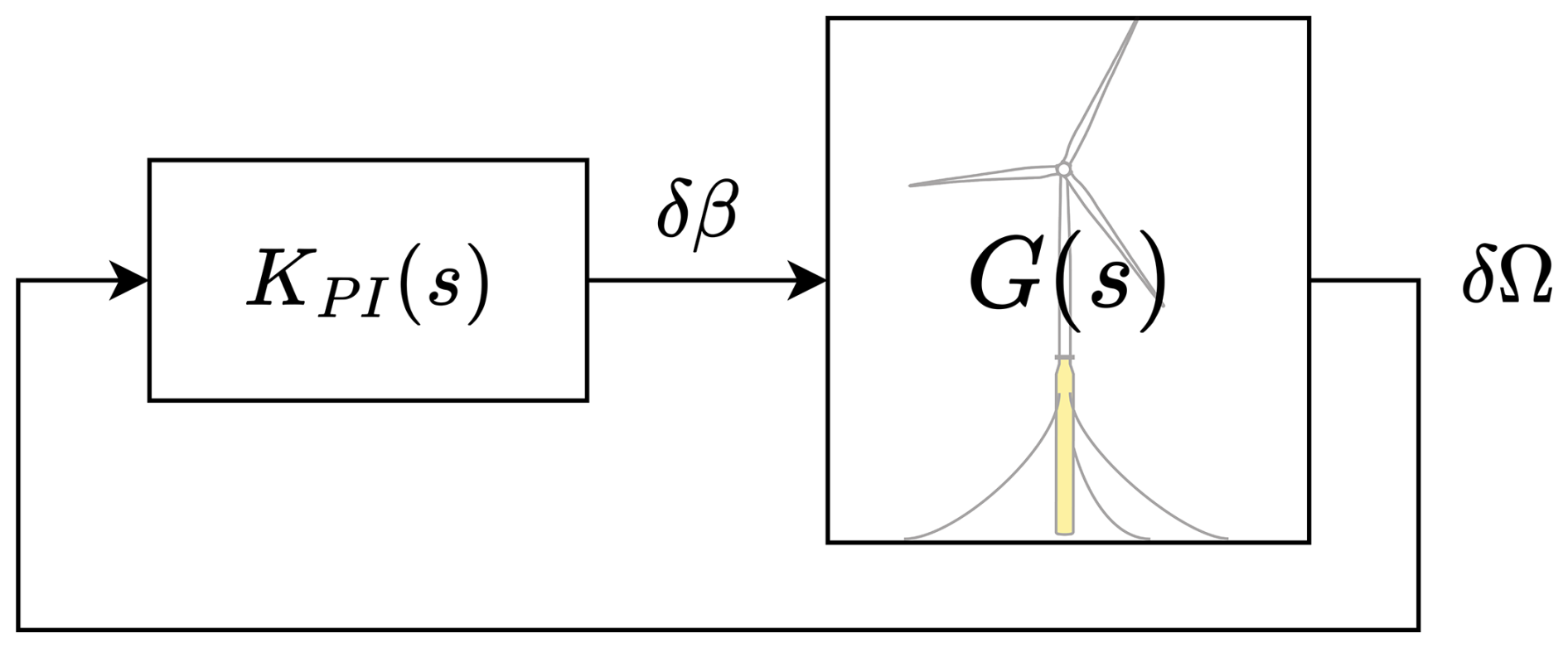
Figure 4Block diagram of the FOWT closed-loop system, where G(s) represents the plant model, and KPI(s) represents the collective blade pitch controller.
This section reviews various control strategies proposed for mitigating the negative damping instability in FOWTs, beginning with the most straightforward approaches and progressing towards more complex solutions involving additional sensors and actuators. Each method is evaluated in terms of its ability to address the negative damping effect and its effectiveness in overcoming the bandwidth limitation imposed by the RHPZs. Ultimately, the analysis concludes that only the incorporation of an additional actuator can effectively alleviate the constraint on closed-loop bandwidth.
Figure 4 shows the block diagram of the closed-loop FOWT system with the simple feedback PI controller. Each block represents a linear TF, with G(s) mapping β, the collective blade pitch angle, to Ω, the generator speed, while KPI(s) is the collective blade pitch controller.
Neglecting the floating platform dynamics during the FOWT control design often yields instability at the operating points containing RHPZs, since the high control bandwidth, associated with the high feedback control gains, causes platform pitch excitation (Jonkman, 2008). At first, one might expect exponential growth in the response due to negative damping, but this is not the case because of the non-linear dynamic coupling between the different FOWT modes. Yet the FOWT keeps oscillating back and forth without reaching a steady state, which is still undesirable. There are several ways to mitigate this challenging problem. Thus, in the remainder of this section, the conventional solutions are presented, followed by our proposed solution in the next section.
3.1 Detuning
A common approach to mitigating negative damping instability is to reduce the bandwidth of the blade pitch controller below the platform's natural frequency (Larsen and Hanson, 2007; Jonkman, 2008; van der Veen et al., 2012). While this stabilises the system, it compromises generator speed tracking performance at operating points where detuning is implemented.
Detuning introduces a control performance trade-off in the vicinity of rated wind speeds. Lowering the closed-loop bandwidth to maintain stability compromises the system's disturbance rejection capability and degrades power tracking performance.
3.2 Robust scheduled tuning
As previously mentioned, stability can be maintained in the presence of RHPZs by detuning, such that the natural frequency of the closed loop is below the frequency of the RHPZs, which is approximately equal to the resonant frequency of the platform pitch (Lemmer et al., 2020). Applying the global detuning approach means that the bandwidth and the damping ratio are constant across all the operating points, which is inefficient since it sacrifices better tracking performance. According to Figs. 2 and 3, the limitation set by the RHPZs varies according to the operating point.
Rather than applying a global detuning strategy at all the operating points as described in the previous section, a more effective method involves individually tuning the PI controller for the fastest achievable response at each operating point, while still ensuring the stability of the linear system (Lemmer et al., 2020; Yu et al., 2020; Stockhouse et al., 2024b; Stockhouse and Pao, 2024). However, achieving a stable system is not sufficient in control design; the system must also exhibit adequate stability margins, which indicate how close it is to instability and how robust it is to disturbances. The gain and phase margins are classical robustness measures that have been used for a long time in control system design, but they are not always good robustness indicators when it comes to the Nyquist stability criterion. However, the stability margin sm can be used instead to give a more general robustness measure. On the one hand, it unites both the gain and phase margins under a single parameter; on the other hand, it ensures that the Nyquist stability criterion is met. The stability margin sm is also a good robustness measure of nominally stable systems against model uncertainties. The stability margin of a closed-loop system is defined as the shortest distance between the Nyquist curve of the system's loop transfer function L(s)=G(s)K(s) and the critical point at in the s plane, and it expresses how well the Nyquist curve of the loop transfer avoids the critical point. While there is no representation of sm in the Bode plot of the loop transfer function, sm is related to the peak magnitude Ms of the sensitivity closed-loop transfer function through , with Ms being the ℋ∞ norm of S(s) as per Åström and Murray (2021):
System stability robustness is a critical design priority for FOWTs, often leveraged in prior studies to calibrate both SISO (Lemmer et al., 2020) and MIMO control architectures (Stockhouse et al., 2024b; Stockhouse and Pao, 2024). The contour plots in Figs. 5 and 6 depict the stability margin and the closed-loop bandwidth evaluated over a range of the proportional-integral (PI) control parameters, namely the natural frequency (ωc) and the damping ratio (ζc), showcasing the stable design space of the controller parameters, with the white-coloured region determining the unstable region. The stable region becomes larger as wind speed increases and the effect of the RHPZs fades according to Fig. 3, which allows for more freedom to increase the controller gains and thus increase the closed-loop bandwidth without destabilising the system. It is important to mention that a stable design space means that the combination of the control parameters means a stable closed-loop system (i.e. not having right-half-plane poles). Although the stable design space is extended at higher wind speeds, some combinations of the controller parameters would significantly increase the controller aggressiveness, leading to instability in the non-linear simulations.
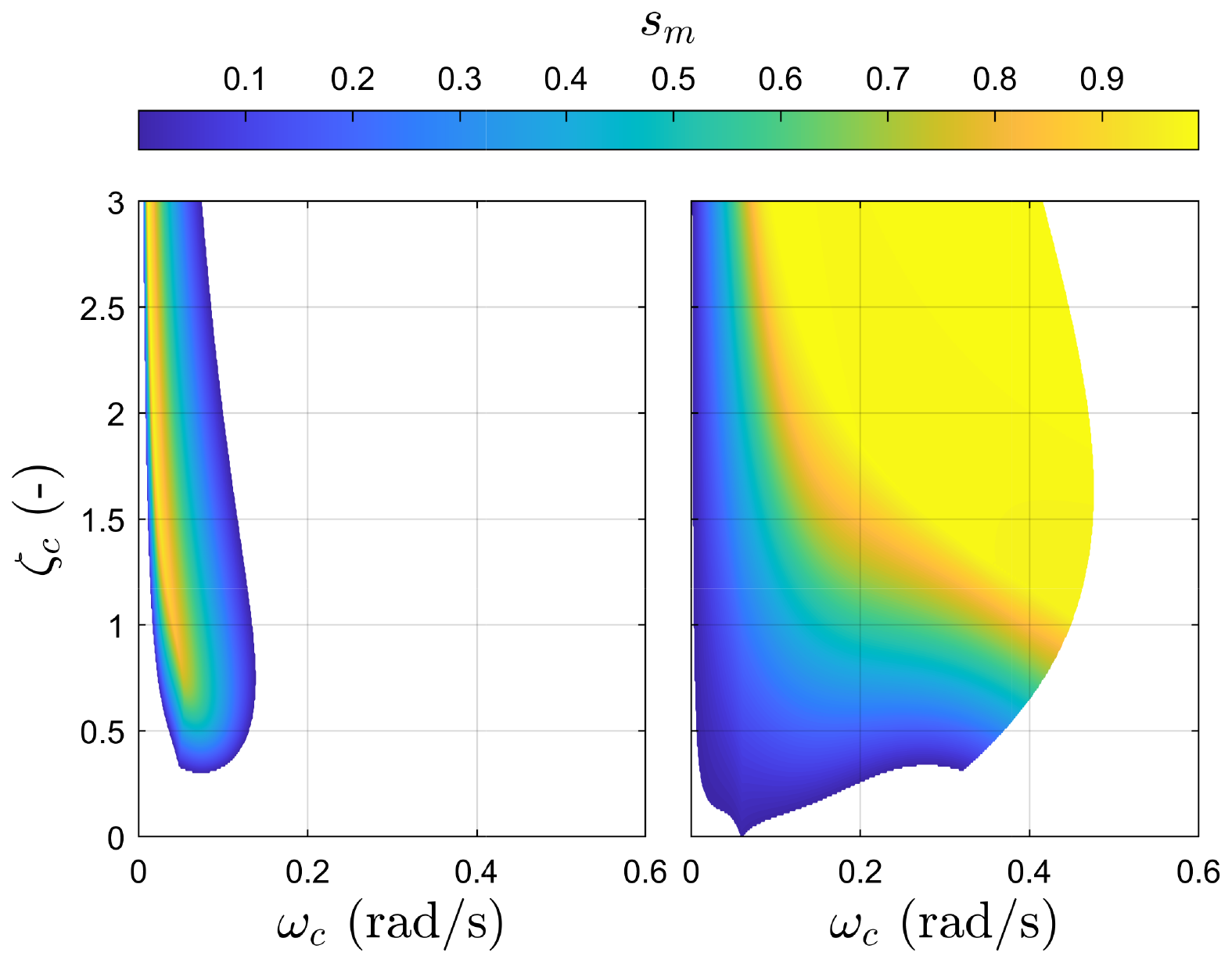
Figure 5Stability margin contours across the natural frequency ωc and damping ratio ζc of the PI controller, shown at two different operating points: near-rated ( m s−1) and near cut-out ( m s−1) wind speeds. The white region indicates a destabilising combination of ωc and ζc.
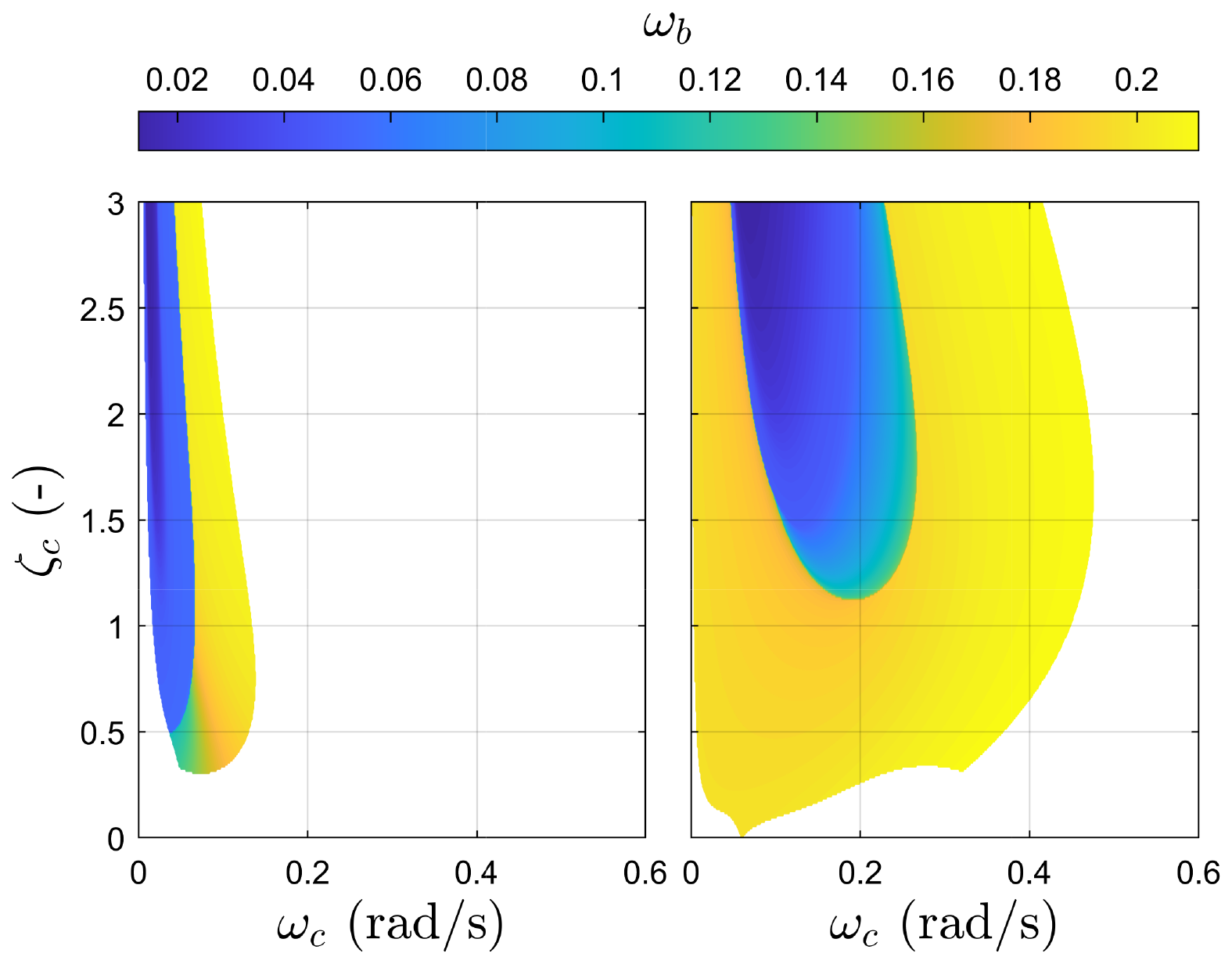
Figure 6Closed-loop bandwidth contours across the natural frequency ωc and damping ratio ζc of the PI controller, shown at two different operating points: near-rated ( m s−1) and near cut-out ( m s−1) wind speeds. The white region indicates a destabilising combination of ωc and ζc.
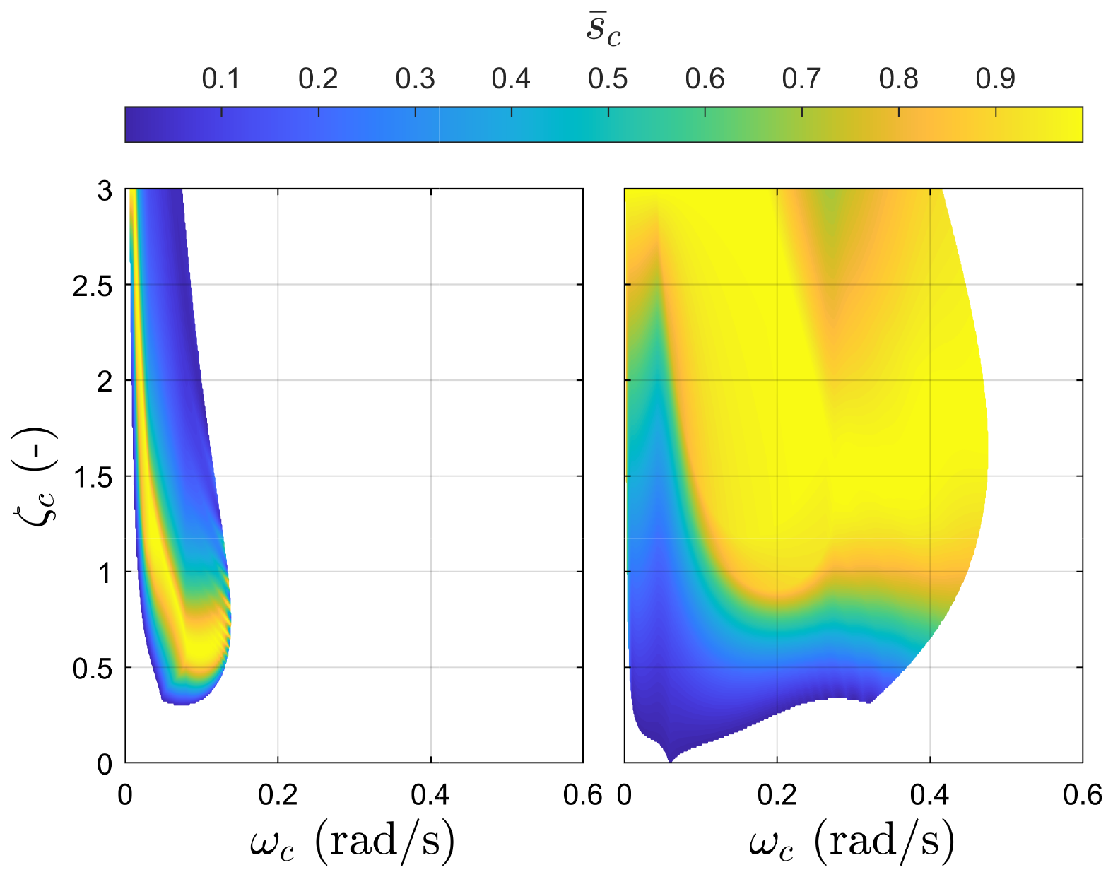
Figure 7Control effort margin contours across the natural frequency ωc and damping ratio ζc of the PI controller, shown at two different operating points; near-rated ( m s−1) and near cut-out ( m s−1) wind speeds. The white region indicates a destabilising combination of ωc and ζc.
Increasing the closed-loop bandwidth reduces the stability margin, pushing the system closer to instability, as shown in Figs. 5 and 6. Consequently, achieving robust tuning of the PI controller requires a trade-off between stability robustness and closed-loop bandwidth, as these are competing objectives. Inspired by the work done in Lemmer et al. (2020), Stockhouse et al. (2024b), and Stockhouse and Pao (2024), an optimisation-based tuning integrating the two key system properties – the stability margin and the closed-loop system bandwidth while considering the actuator limits – is thus employed. The PI controller is parameterised by ωc and ζc collected in the vector x∈ℝ2. A scalar objective function is then constructed with the following requirements: (i) maximise robust stability margin, (ii) maximise closed-loop bandwidth, and (iii) maintain acceptable actuator activity. When formulating J(x), an important aspect is considering the actuator activity to avoid saturation. The control sensitivity function K(s)S(s) is a good indicator of the actuator activity. Inspired by sm, the control effort margin sc is introduced here as a measure of actuation robustness. A low sc indicates high sensitivity to disturbances, risking actuator saturation. Analogous to sm, we propose the variable sc that is related to the peak magnitude of the control sensitivity function Mc through , where Mc is defined as Mc=∥K(s)S(s)∥∞. The objective function is then formulated as
where , wbw, and are weights adjusting the importance of the stability margin, the bandwidth, and the control effort margin, respectively. Regularisation terms may be added to the objective function to fulfil control objectives such as minimising the generator speed and power oscillations, as well as reducing the loads (Lemmer et al., 2020) and limiting the control gains (Stockhouse and Pao, 2024). Despite acknowledging that regularisation terms may be added to limit the gains, Stockhouse and Pao (2024) do not explicitly integrate actuator limits within their objective function formulation. Neglecting the actuator limits in the objective function would result in controller saturation. Conversely, Eq. (24) explicitly incorporates this constraint, ensuring the controller remains within operational limits. The objective function in Eq. (24) is then implemented in the optimisation problem in the form
In this framework, the optimisation variables (denoted as x) are the tuning parameters influencing three critical system properties: the stability margin, the closed-loop bandwidth, and the control effort margin. A systematic tuning method, leveraging the simplified dynamic system, enables rapid recalibration of control settings and assessment of steady-state behaviour. The core objective is to maximise the closed-loop bandwidth while minimising the inverse of the stability margin. Focusing on the inverse of the stability margin ensures the closed-loop stability of the system, while parameters that cause instability are dropped out. After formulating and weighting the objective function, a locally optimal solution is derived using a gradient-based optimisation solver.
Based on Eq. (24) and according to Figs. 5 and 6, we have two competing objectives, as an increase in the closed-loop bandwidth leads to a reduction in the closed-loop stability margin. Therefore, tuning the PI controller gains to achieve both objectives is not trivial, especially since finding a globally optimal solution is not guaranteed with gradient-based optimisation. Accordingly, a multi-objective optimisation problem is formulated over a set of continuous input variables 𝒳⊂ℝd, called the d-dimensional design space (Lukovic et al., 2020). The optimisation goal is to maximise both the stability margin and the closed-loop bandwidth through minimising the vector of the objectives defined as , with being the vector of input variables and f(𝒳)⊂ℝn the m-dimensional image representing the performance space.
The conflicting nature of the objectives does not always allow for the finding of a single optimal solution to the maximisation problem but a set of optimal solutions as shown in Fig. 8, referred to as the Pareto set 𝒫s⊆𝒳 in the design space and the Pareto front in the performance space (Lukovic et al., 2020).
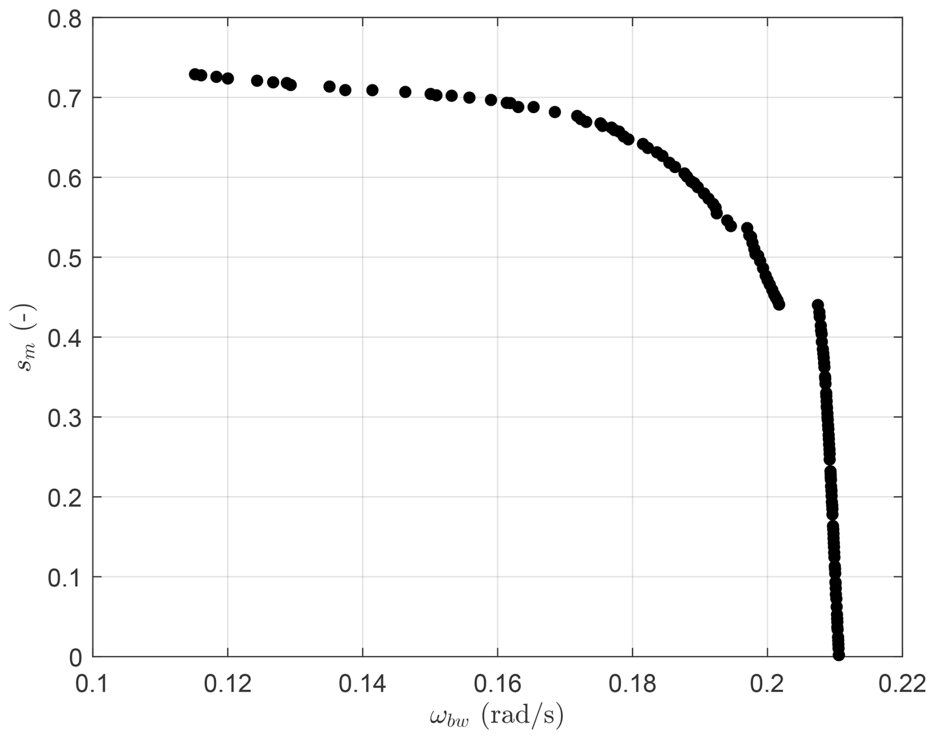
Figure 8The Pareto front resulting from the multi-objective optimisation. Each data point indicates an optimal combination of the PI controller parameters ωc and ζc.
The Pareto front in Fig. 8 clearly illustrates the trade-off between closed-loop stability and bandwidth. Beyond a certain threshold, further increasing the bandwidth significantly compromises system stability. The knee point on the Pareto front represents an optimal balance between these competing objectives, making it a favourable region for selection. However, caution is needed when considering solutions in the upper-right region of the Pareto front. While they offer higher bandwidth, they also lead to excessive pitch activity, rendering them impractical due to actuator constraints. The control gains used in this work are tabulated in Table 2.
Table 2Robustly scheduled control gains of the PI controller for the NREL 5 MW RWT.

3.3 Multi-loop control
A standard method to address negative damping instability involves implementing a secondary feedback loop that incorporates the platform pitch velocity signal. This technique can utilise blade pitch (van der Veen et al., 2012) or generator torque actuation (Fischer, 2013), representing a shift towards MIMO control strategies. The approach seeks to reduce the coupling between competing aerodynamic forces – rotor torque and thrust – while maintaining generator speed regulation via blade pitch adjustments. In this work, the platform pitch rate is employed as the fore-aft velocity signal for the secondary feedback loop. The study evaluates both blade pitch damping and generator torque for parallel compensation, finding that combining the two actuators balances their advantages and limitations.
In Eq. (14) of the state-space model, the matrix element A32 represents the dynamic coupling between platform pitch velocity and rotor acceleration . Nullifying this term diminishes the influence of platform pitching on rotor speed tracking. This tuning strategy does not directly suppress platform motion but counteracts its destabilising effect on speed regulation, thereby enhancing closed-loop stability.
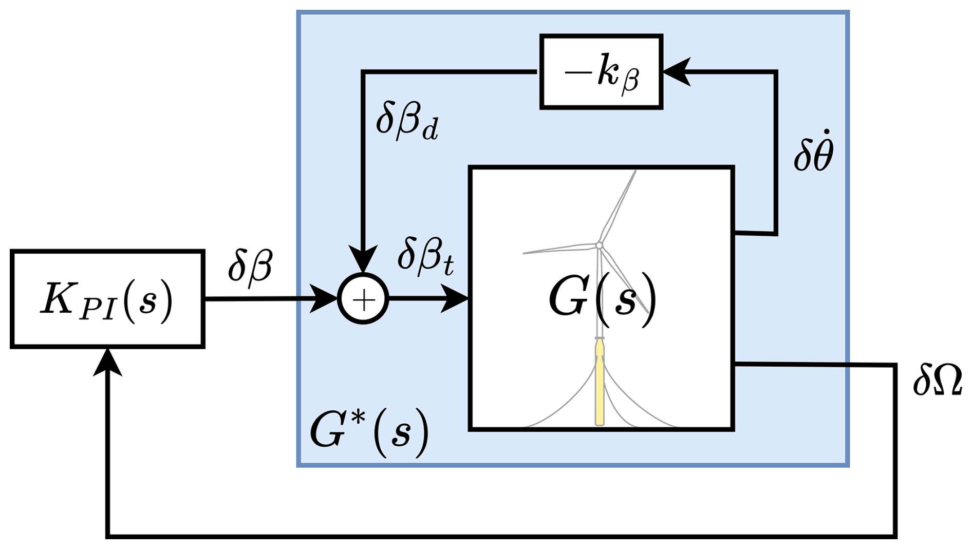
Figure 9Block diagram of the multiple-input single-output (MISO) controller with the additional blade pitch loop.
3.3.1 Additional blade pitch loop: MISO control structure
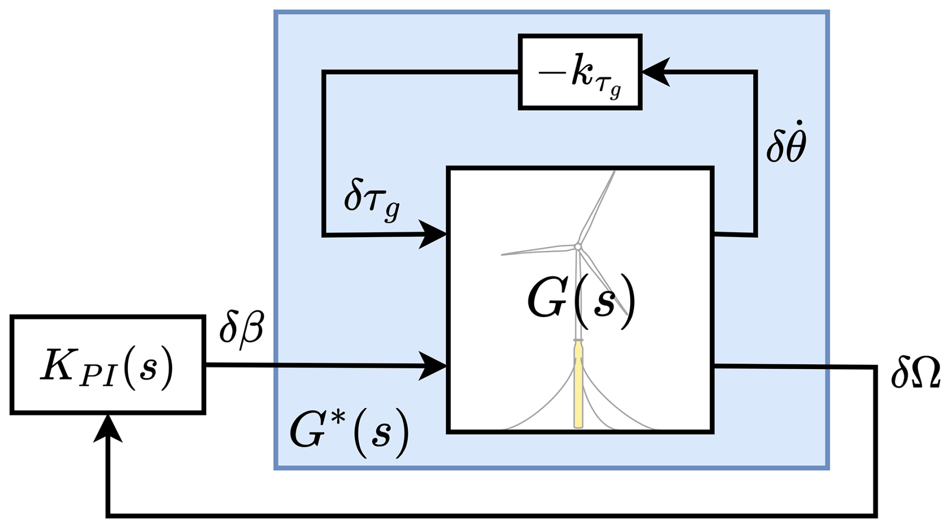
Compensation using blade pitch feedback, as shown in Fig. 9, is achieved by adding an extra term to the element A32, corresponding to the closure of the inner loop, where the static gain kβ is scheduled to be consistent with the PI controller gains for each operating point. The blade pitch damping approach uses proportional feedback of the platform pitch velocity (Jonkman, 2008; van der Veen et al., 2012):
Therefore, the overall blade pitch signal becomes
Closing the inner feedback blade pitch loop by substituting δβ from Eq. (27) in Eqs. (3) and (12), the system matrix of the inner loop A* becomes
This extra blade pitch in Eq. (26) is added to the collective blade pitch command from the PI controller, KPI(s) in Fig. 9, before the actuator saturation limits are applied. At first glance, it is observed that the extra feedback loop affects not only the state transition from the platform pitch velocity to the generator speed, as shown by element , but also the damping of the platform pitch mode shown by element . This indicates that this parallel loop can be used for two control objectives: either to compensate for the RHPZs or to increase the platform pitch damping.
Solving for a gain that makes leads to full compensation of the effect of platform pitch on the generator speed. However, due to blade pitch coupling with both aerodynamic torque and thrust, such a gain reduces the effective system fore-aft damping as a side effect. It is, therefore, sensible to choose a smaller gain to partially compensate the fore-aft motion, which can be achieved by multiplying the parallel compensation gain by a static gain ξβ. The parallel compensation gain for blade pitch then becomes (Hegazy et al., 2023a; Stockhouse and Pao, 2024)
The value of determines the degree of partial compensation from the blade pitch actuator to alleviate the effect of the platform pitch motion on the generator speed at the expense of less fore-aft damping. Should the objective of decoupling the drivetrain and the platform dynamics be sought, extra filtering is required to change its dynamics; otherwise, the system damping worsens and it becomes unstable. However, if the control objective shifts to increasing the fore-aft damping, that will be at the expense of reducing the drivetrain damping, thus resulting in less generator speed tracking performance. Similar to Eq. (13), the platform pitch dynamics in the second row of A* is represented in standard form as
where is the new desired damping ratio of the platform pitch DOF, without any change in its natural frequency. According to Eq. (30) and taking Eq. (13) into account, kβ can be parameterised as (Stockhouse and Pao, 2024)
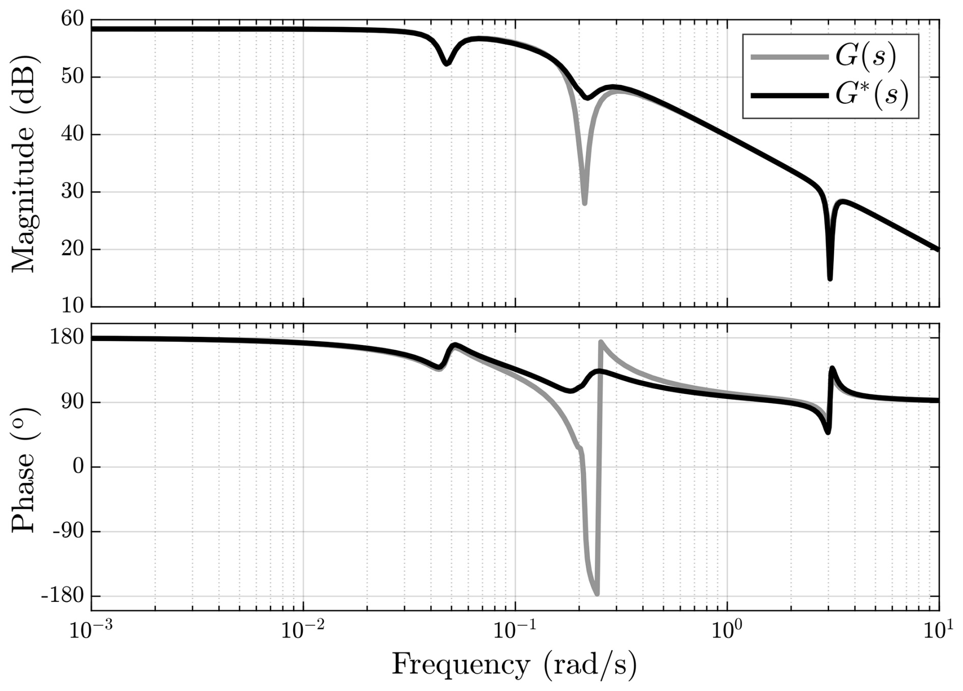
where Δζp represents the desired change in the platform damping. The extra feedback loop acts as a damper, increasing the system damping by moving the poles of , corresponding to the platform pitch mode, away from their respective zeros. While the RHPZs remain unaffected, setting restrictions on the closed-loop control performance, which is evident from the phase loss of 180° in Fig. 10, the damper effect is illustrated, highlighting its direct influence on the outer loop . It is observed that the rotor dynamics deteriorate by adding the blade pitch damper as the depth of the anti-resonance dip increases, indicating an increase in generator speed oscillations and thereby affecting power production within the frequency range of the fore-aft mode.
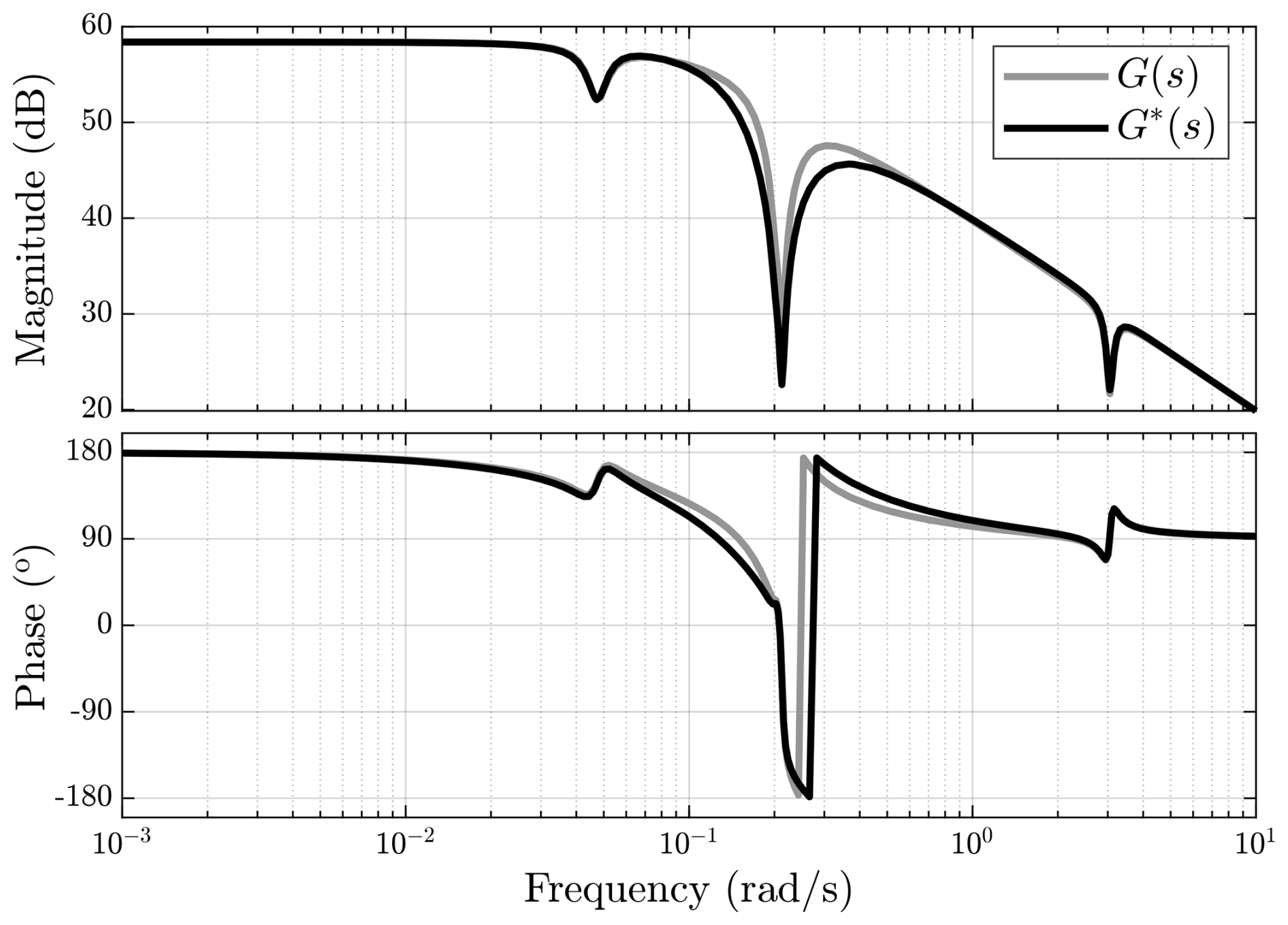
Figure 10Bode plot comparing the channel mapping δβ to δΩ of the original transfer function G(s), with the modified transfer function G*(s) depicted in Fig. 9, obtained after closing the inner loop from platform pitch velocity to blade pitch.
Although the MIMO plant G(s) does not have any transmission zeros, the poor generator-speed tracking performance is attributed to the persistence of the RHPZs in , as they are not affected by the parallel inner loop and still impose a limitation on the PI controller bandwidth. This is confirmed by checking the numerator of , whose damping term becomes
As shown in Eq. (32), the RHPZs are indeed unaffected since the inner-loop contribution cancels, thus leaving the RHPZs condition in Eq. (18) with no change.
3.3.2 Parallel compensation: MIMO control structure
So far, the previous control strategies proved not to be able to compensate for the deteriorating effect of the RHPZs. The only way to move zeros is by parallel compensation, , which, if y is a physical output, can only be accomplished by adding an extra input (actuator) (Skogestad and Postlethwaite, 2005).
As mentioned earlier, the presence of zeros implies the blockage of certain input signals. In this case, the blade pitch input is blocked due to the emergence of RHPZs, which is depicted in Fig. 10 where anti-resonance dips exist, indicating a significant attenuation of the input signals at those frequencies. Therefore, instead of using the blade pitch in the parallel loop, the generator torque can be used as illustrated in Fig. 11, thus taking a step towards MIMO control. Unlike the blade pitch, the generator torque compensation is different as when GΩ,β is closed with the generator torque parallel compensation loop, the RHPZs move to the LHP. At optimal gain, the RHPZs vanish from , which is the TF representing GΩ,β after closing the generator torque parallel loop, indicating that the system became minimum phase. The generator torque parallel compensation uses proportional feedback of the platform pitch velocity (Fischer, 2013):
Closing the inner feedback generator torque loop by substituting δτg from Eq. (33) in Eqs. (3) and (12), the system matrix of the inner loop becomes
Therefore, to eliminate the effect of platform pitch rate on the rotor dynamics, set . Consequently, the parallel compensation gain for the generator torque actuator is (Fischer, 2013; Hegazy et al., 2023a; Stockhouse and Pao, 2024)
where is introduced as a tunable parameter determining the intensity of parallel compensation since it is not necessary to remove the RHPZs totally. Having a glance at the numerator of , it can be noticed that adding the parallel compensation loop modifies the damping term in the numerator by modifying the aerodynamic coefficient, μaero in Eq. (18), to a new one, which in return, leads to a different zeros locations. The new aerodynamic coefficient becomes
According to Eq. (36), the parallel compensation feedback loop makes it possible to manipulate the zeros of GΩ,β and compensate for the RHPZs by pushing them towards the LHP (Fischer, 2013; Yu et al., 2018; Hegazy et al., 2023a; Stockhouse et al., 2024b; Stockhouse and Pao, 2024). The level of compensation is tunable based on the tuning of the gain . The higher , the more the RHPZs move towards the LHP until they migrate to the LHP, indicating the removal of those RHPZs. Consequently, the bandwidth of the PI controller can be increased above the platform pitch mode. This is clear in Fig. 12, as the depth of the anti-resonance dip, corresponding to the RHPZs, decreases meaning that the limitation set by the RHPZs is vanishing, which gives the opportunity to increase the aggressiveness of the PI controller.
The main drawback of this approach is the generator torque limit for parallel compensation that can be supplied by the actuator. The usage of the full-compensation gain () eliminates the RHPZs, thus turning the system to minimum phase for all operating points; however, the constraint imposed by the τg saturation restrains actuator signals exceeding the maximum generator torque. Reducing the compensation gain with is rather advantageous in practice, as on the one hand, it prohibits the generator torque actuator from saturating; and on the other hand, it reduces the drivetrain loads (Hegazy et al., 2023a). With , the RHPZs are partially compensated, allowing higher achievable bandwidth and, hence, improved performance.
3.3.3 Parallel compensation: SIMO control structure
Hegazy et al. (2023a) showed that the feedback of the platform motion is not necessary for parallel compensation, as only generator speed can be used. They went on to show the control structure of the blade pitch and the generator torque controllers. It was learnt from ℋ∞ control synthesis that the blade pitch maintains the PI structure, while the generator torque requires a band-pass filter (Hegazy et al., 2023a). From its name, a band-pass filter is a control element that is only operational at a specific frequency band. Thinking about it, such a control structure, resulting from the ℋ∞ synthesis, for the generator torque control loop is reasonable since the generator torque input should not operate across all frequencies like in Fischer (2013), but only around the RHPZs frequency where the blade pitch input is blocked. Therefore, the generator torque control loop takes over. Therefore, in the current paper, an inverted-notch filter was chosen to be placed on the generator torque input, where the inverted notch is only operational at a single frequency (Hegazy, 2025).
Figure 13 illustrates the control structure defined in Hegazy et al. (2023a), where the blade pitch controller maintains the PI control structure as
where kp and ki are the proportional and the integral gains, respectively. As for the generator torque channel, an inverted notch is applied as (Hegazy, 2025)
Consequently, the SIMO controller takes the form
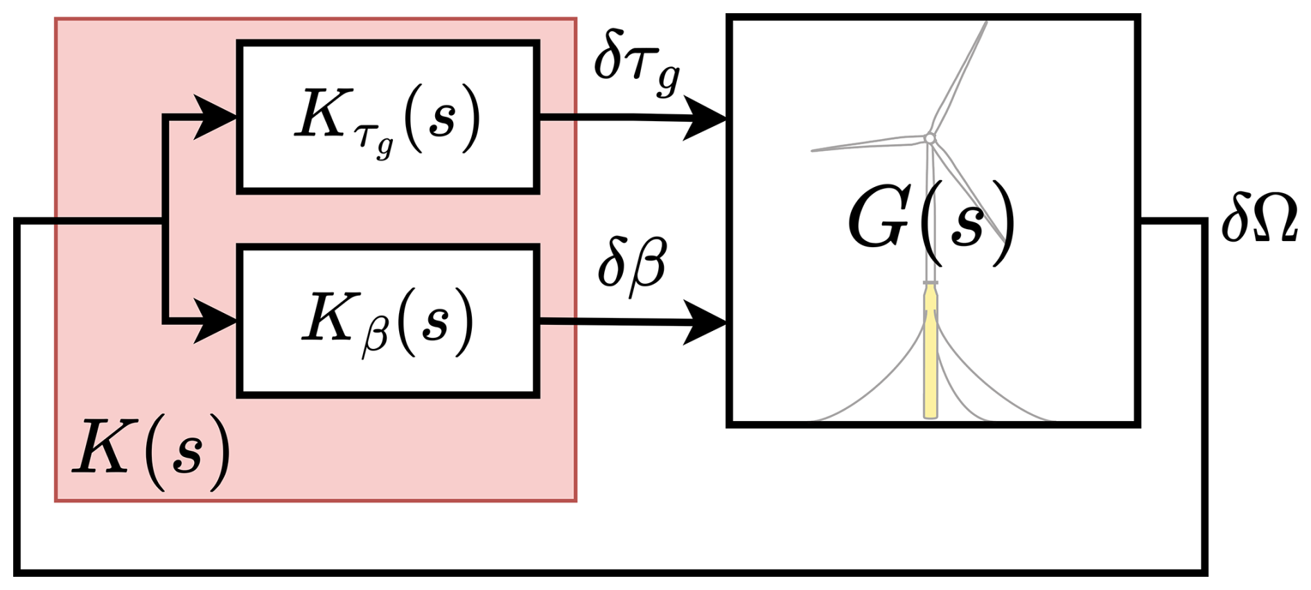
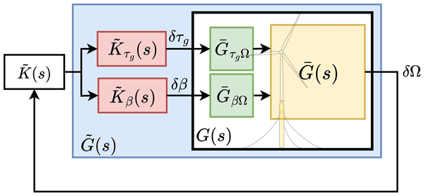
Figure 13Block diagram of the FOWT closed-loop system, where G(s) represents the plant model, and K(s) represents the SIMO structure feedback controller composed of two SISO controllers: controller acting on the generator torque actuator and Kβ(s) active on the blade pitch actuator.
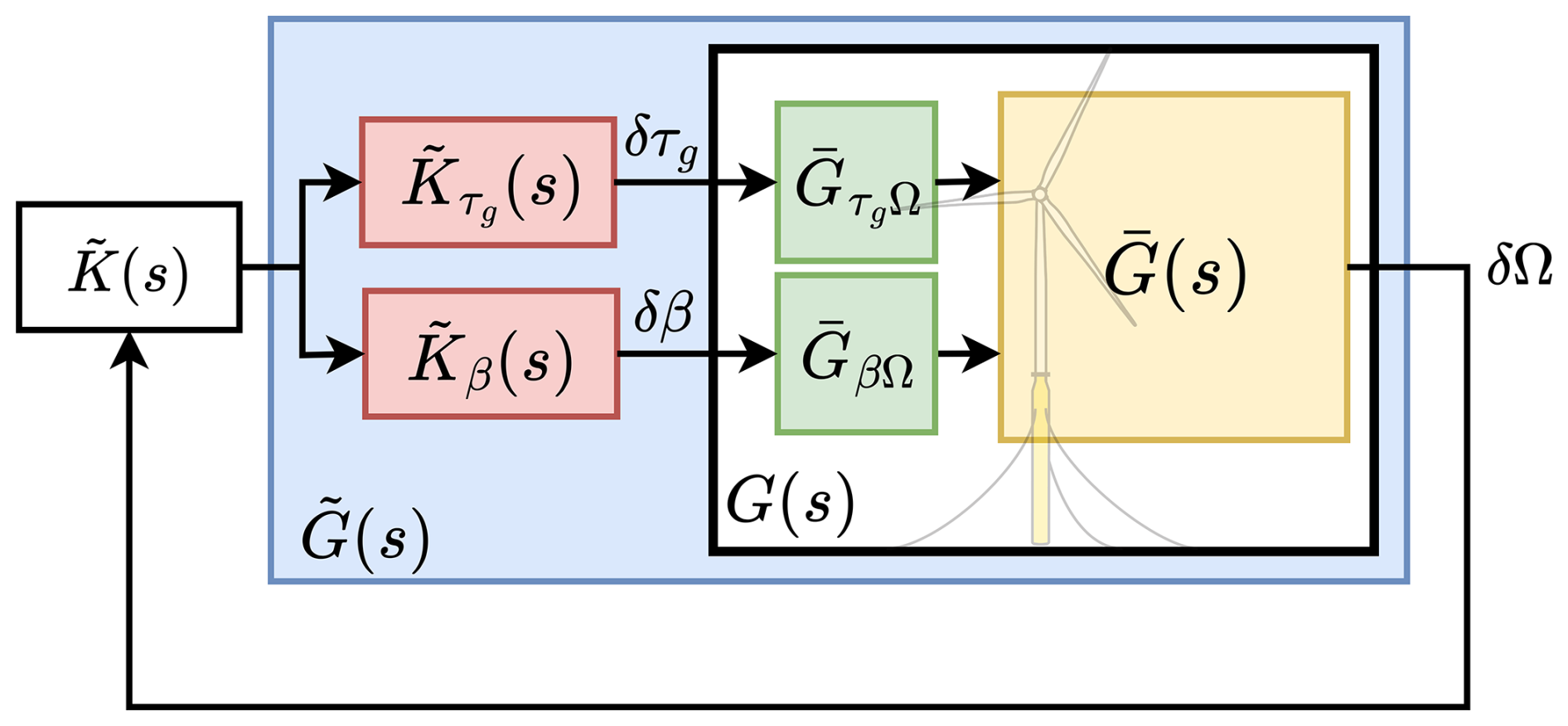
Now that the need for SIMO control to deal with the negative damping problem has been established in Fig. 13, tuning each controller separately sounds complicated due to the dynamic interactions between the MIMO channels that would arise when either of the controllers is modified. Therefore, the objective is to turn the SIMO system into a SISO one. In order to do that, the original MISO plant G(s) is normalised to such that the magnitude of both the blade pitch and the generator torque input channels becomes unity so that both control inputs are of comparable effect. Afterwards, a linear combination of the two control elements and is combined with normalised MISO plant . This is depicted in Fig. 14 where the extra blocks are integrated with the plant such that there is a new plant . Therefore, the new SISO plant is the result of the linear combination of both control channels as
where the controllers Kβ(s) and have to be decomposed such that
where an inverted-notch filter is the outcome of combining a high-pass filter and an integrator:
while a PI controller results from the combination of a proportional-differential (PD) and an integrator:
where the PD controller gains are
In this work, the damping ratio of the inverted notch () is set to 0.5, and its desired natural frequency () is placed at the RHPZ location of GΩ,β. The gain in is a static gain to either crank up or reduce the overall gain of the controllers and simultaneously, kept at 1 in this paper. The objective is to tune one single controller instead of multiple control components, which would complicate the control tuning process.
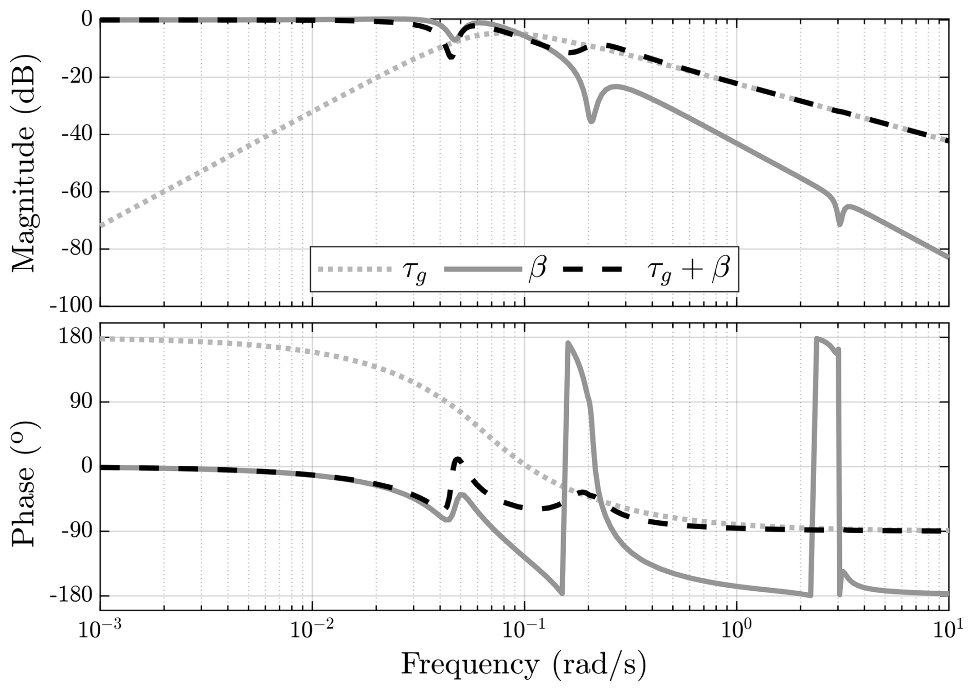
Figure 15Bode plot of the normalised MISO plant illustrating the frequency response of each control channel separately (solid lines) as well as the response of the SISO plant in case of the linear combination of both actuators (dashed line) where the blade pitch actuator is active until a certain frequency before its authority deteriorates, thus the generator torque actuator takes over from that frequency onwards.
The generator torque actuator is only active within the RHPZs frequency band to take over the control from the blade pitch, which is limited by the non-minimum phase behaviour around that band. This is depicted in Fig. 15, where the limitation set on the blade pitch, while regulating the generator speed, is lifted by the generator torque, and the linear combination of both actuators can lead to an increase in the control bandwidth, as shown in Fig. 16. The two vertical lines depict the closed-loop bandwidth of each controller. Clearly, the baseline feedback PI controller has its bandwidth constrained by the RHPZs, which are also around the platform pitch natural frequency. Looking at the loop transfer function of the linear combination of both actuators, we can see the jump in the bandwidth that the SIMO controller makes over the baseline controller, as the SIMO controller intersects with the 0 dB line much later than the baseline controller. Moreover, the anti-resonance dip that corresponds to the RHPZs existing in the Bode plot of the baseline controller is eliminated in the SIMO controller, reflecting on its robustness as it significantly increased with a phase margin of almost 90°.
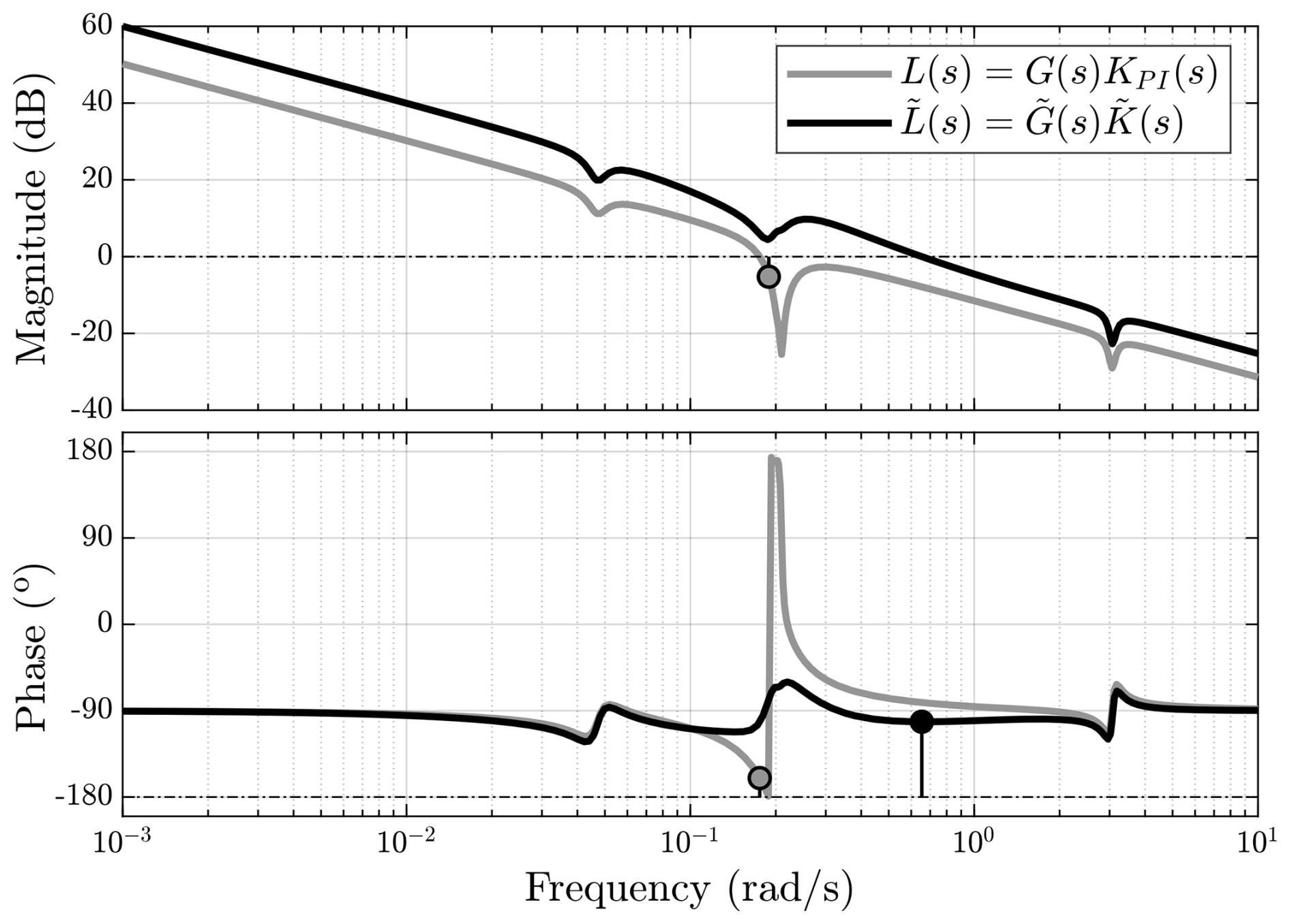
Figure 16Bode plot of the loop transfer function L(s) of the baseline controller KPI(s) and the SISO plant G(s) (grey), along with the loop transfer of the artificial SISO plant in Fig. 14 and , illustrating the effect of the linear combination of both actuators on increasing the bandwidth of the closed-loop system indicated by the vertical lines in the phase plot.
The FOWT system (NREL 5 MW RWT; Jonkman et al., 2009, atop OC3 floater; Jonkman, 2010) was simulated in OpenFAST (NREL, 2025a) with the five controllers discussed in Sect. 3 in environmental conditions of turbulent wind and irregular waves. The simulations were conducted in the above-rated Region 3 (vrated=11.4 m s−1) at average wind speeds ranging from 12 to 24 m s−1, with TurbSim (NREL, 2025b) to simulate the turbulent wind field, where the International Electrotechnical Commission (IEC) Kaimal spectral model was used as a turbulence model with a turbulence intensity of 14 % and a wind shear exponent of 0.14. The irregular waves were generated using JONSWAP spectrum at a significant wave height Hs=3 m and peak period Tp=12 s. All the simulations were performed for a simulation time of 1200 s, with the first 600 s neglected for transients.
An example time-domain simulation at a reference wind speed of 18 m s−1 is illustrated in Figs. 17 and 18. The time traces are complemented with the power spectra for a detailed view of the controllers' performance. Looking at the rotor speed signal in Fig. 17, we can see the significant impact the robust tuning of the SISO PI controller can make in comparison to the Detuned SISO PI controller. The rotor speed's peak-to-peak amplitude of the Robust SISO is significantly reduced compared to the Detuned SISO. This is also evident in the spectral content of its power spectrum, as the rotor speed oscillations are suppressed until 0.1 Hz.

Figure 17Non-linear simulation results for the FOWT system, simulated with each of the controllers described in Sect. 3 at a reference wind speed of 18 m s−1.
For the SISO controller, the generator torque is kept constant and the generator power in Region 3 is directly related to the generator speed. The reduction in the rotor speed oscillations reflects on the generator power, leading to an improved power quality with less fluctuations. However, such an improved performance comes at the cost of actuation. This is to be expected since the increased bandwidth of the Robust SISO means higher control activity, which can be seen in the blade pitch signal with higher spectral content across the frequency range, leading to an increase in the blade pitch variation.
Regarding the MISO controller in Fig. 17, its main objective is to add damping to the closed-loop system, through extra blade pitch action, to compensate for the severe reduction in the overall system damping caused by the negative aerodynamic damping, as explained by Eqs. (18) and (22). In this work, the MISO controller is composed of the Robust SISO controller, and added to it is the inner feedback loop from the platform pitch rate to blade pitch, as shown in Fig. 9. The MISO controller in Fig. 17 appears to be doing slightly better than the Robust SISO in a small frequency segment within the low-frequency region before 0.05 Hz, while no significant difference is observed between both controllers at other frequencies. Similar to the detuned and Robust SISO cases, the generator power follows the same trend as the rotor speed since the generator torque is constant in the case of the MISO controller. This explains the absence of the generator torque curves relevant to the three cases in the power spectrum. The MISO controller blade pitch actuation does not change much from the Robust SISO controller. It simply is a little more active and thus more oscillatory because of the extra blade pitch input added.
As for the MIMO controller in Fig. 17, the generator torque is employed as an extra actuator to provide parallel compensation (Skogestad and Postlethwaite, 2005) to the FOWT system to deal with the RHPZs. Implementing the MIMO controller results in a modest enhancement of rotor speed, as the substantial improvement achieved by the Robust SISO controller over the detuned version significantly limits the potential for further error reduction. With the generator torque not constant anymore, the power variation includes contributions from both generator speed and generator torque, showing a clear drawback of the MIMO controller.
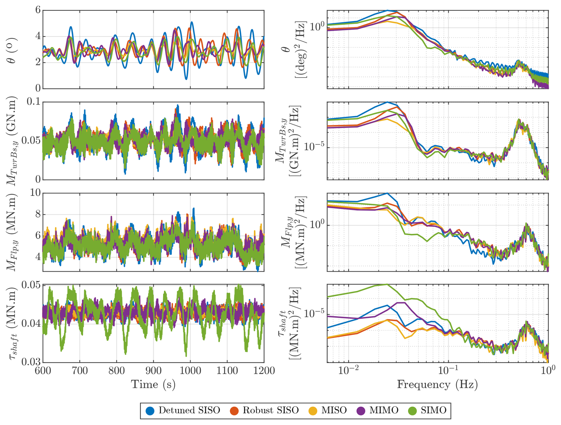
Figure 18Non-linear simulation results for the FOWT system, simulated with each of the controllers described in Sect. 3 at a reference wind speed of 18 m s−1.
Transitioning to the newly proposed control structure, the SIMO controller demonstrates superior performance in generator speed regulation – the primary objective of this controller – particularly when compared to the Detuned SISO controller. While one might expect increased blade pitch activity to achieve better generator speed regulation, this is not the case. Instead, the blade pitch action remains nearly identical to that of the Robust SISO, MISO, and MIMO controllers. This is because, beyond a certain point, generator torque takes over, as previously shown in Fig. 15. Consequently, the generator torque response becomes highly aggressive, exhibiting significant variations to maintain a more stable generator speed signal, even reaching saturation. However, this comes at the expense of power quality, similar to the MIMO controller. Notably, the SIMO controller exhibits an even more aggressive generator torque action than the MIMO controller. A less aggressive tuning of the SIMO controller would reduce the actuator usage and improve the power quality. Nevertheless, if the power quality is the main control objective, a controller aimed at that objective could be synthesised but at the cost of increased drivetrain loads (Stockhouse and Pao, 2024).
Across the above-rated wind speed spectrum, the SIMO controller achieves the lowest rotor speed oscillations, as indicated by the standard deviation, without any notable difference in blade pitch action compared to other controllers (see Fig. 19). However, the generator torque experiences a large increase with the SIMO controller, even at wind speeds where the RHPZs are expected to disappear (above 16 m s−1). This is because, unlike other controllers, the SIMO controller continuously engages the generator torque actuator across all wind speeds, including those without RHPZs. As a result, variations in generator speed have a considerable impact on generator power. In the simulations conducted at reference wind speeds of 12–14 m s−1, the system occasionally operates below the rated wind speed, leading to fluctuations in generator torque. This occurs despite the Detuned SISO, Robust SISO, and MIMO controllers being designed to maintain a constant generator torque with zero standard deviation in Region 3 – a condition that is fully realised at wind speeds above 14 m s−1.
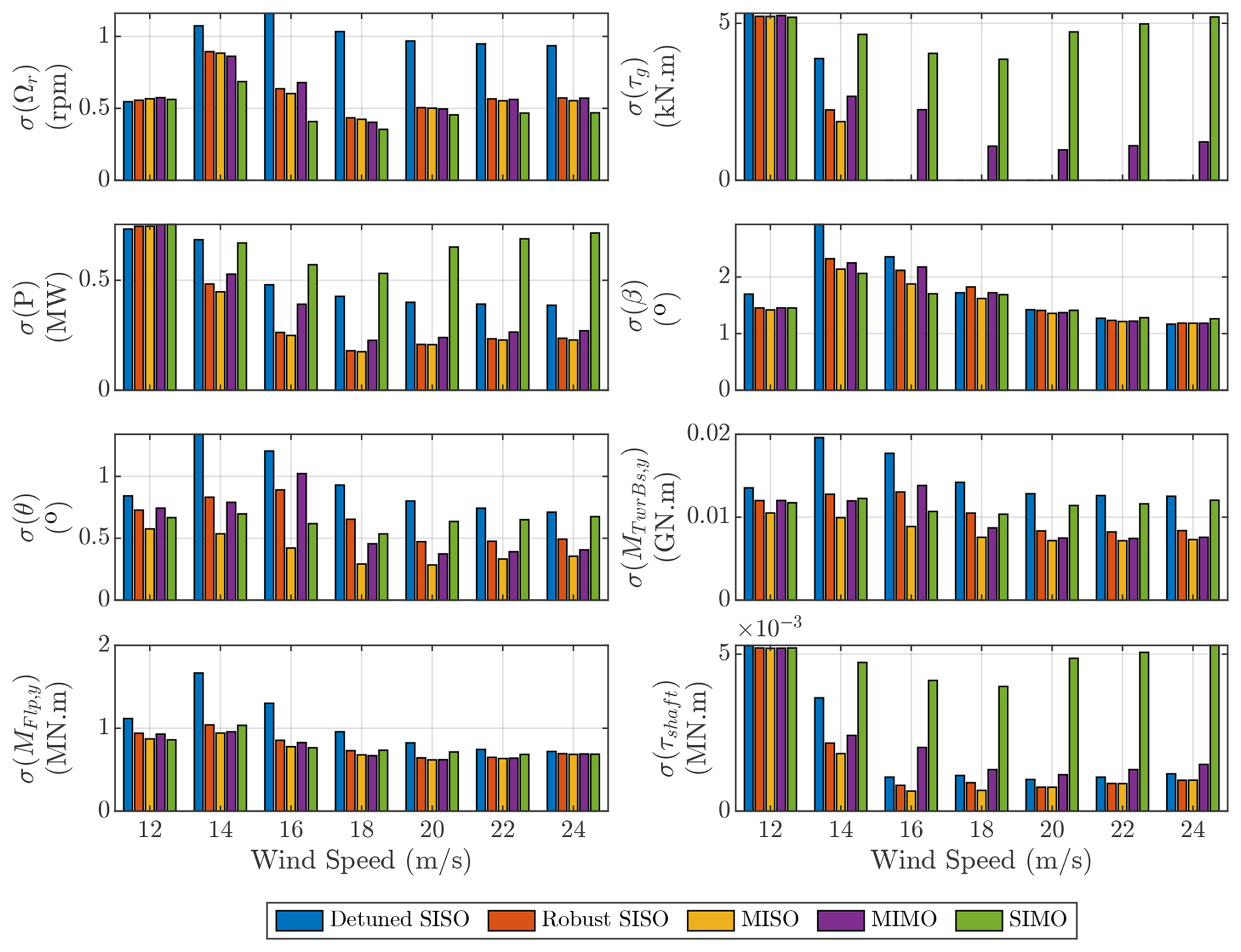
Figure 19Controller performance: standard deviation of different signals from the non-linear simulation results for the FOWT, simulated with each of the controllers described in Sect. 3 at different wind speeds.
Examining Figs. 18 and 19 simultaneously, it is evident that all controllers reduce platform pitch oscillations compared to the fluctuations observed with the Detuned SISO. Among them, the MISO controller achieves the greatest reduction, as it is specifically designed to enhance platform pitch damping – an effect clearly visible in the power spectrum around the platform pitch eigenfrequency (≈0.033 Hz).
Although the SIMO controller is primarily designed to mitigate generator speed fluctuations, it also succeeds in reducing platform pitch oscillations below the Detuned SISO level. While its effectiveness in this regard is lower than that of the MISO and MIMO controllers, this reduction remains beneficial.
Furthermore, this improvement extends to the tower base fore-aft moment (MTwrBs,y), as there is a strong correlation between platform pitch motion and tower base loading. Consequently, controllers that effectively suppress platform oscillations also contribute to significant tower fatigue reduction.
Regarding the blade-root flapwise moment (MFlp,y), all controllers outperform the Detuned SISO across all wind speeds, as shown in Fig. 19. This improvement is evident at low frequencies up to 0.1 Hz, after which there is a slight drop in performance, temporarily exceeding the level of the Detuned SISO. Beyond this point, all controllers converge, exhibiting no significant differences, as depicted in Fig. 18.
Rotor-shaft torsional loading (τshaft) is a well-known drawback of torque feedback in wind turbine control systems. While both the Robust SISO and MISO controllers exhibit smaller shaft loading excursions compared to the Detuned SISO, the MIMO and SIMO controllers, which rely on torque feedback, introduce greater fluctuations in shaft torsional loading. As shown in Fig. 18, this effect is particularly pronounced in the SIMO controller, which exhibits elevated shaft loading variations across all wind speeds, as further illustrated in Fig. 19.
Based on these findings, the authors recommend an adaptive approach, where different proposed controllers are alternated depending on environmental conditions and control objectives. For example, at certain times, the turbine operator may prioritise minimising generator speed oscillations and activate the corresponding controller. At other times, the focus may shift to reducing structural loading, necessitating a different control strategy. Since no single controller can simultaneously optimise all objectives – some of which may be conflicting – dynamic selection based on operational priorities is advised.
Another recommendation is to incorporate a feedforward control strategy to reduce dependence on reactive feedback control. If an accurate preview of disturbances affecting the FOWT is available, a LiDAR feedforward controller (Schlipf et al., 2020) targeting the wind turbulence and a wave feedforward controller (Hegazy et al., 2023b, 2024) targeting the wave forces can be implemented to mitigate the effects of wind and wave disturbances on the FOWT, respectively. This approach alleviates the need for a high-bandwidth feedback controller, as the feedforward controllers would handle most of the disturbance rejection.
A new fixed-structure controller has been developed for FOWTs to effectively mitigate the well-known “negative damping” instability and address the non-minimum phase behaviour introduced by the persistent RHPZs in GΩβ. Designed specifically for generator speed regulation, the proposed controller was evaluated through non-linear simulations in OpenFAST, where it outperformed the existing FOWT controllers from the literature. Furthermore, it demonstrated robustness in a high-fidelity simulation environment, effectively handling additional system dynamics.
The primary advantage of the proposed FOWT controller is that it operates without requiring any additional sensors, preserving the conventional SISO configuration by relying exclusively on generator speed measurement. This approach enhances robustness, as incorporating extra signals can increase sensitivity to unmodelled dynamics. Additionally, the controller can be regarded as an artificial SISO controller, as shown in Figs. 14 and 15, where the plant transfer function is pre-filtered to achieve the desired control performance.
While the MIMO controller features a simpler control structure compared to the SIMO controller, the SIMO configuration provides built-in redundancy within the FOWT system, ensuring continued operation in the event of floating platform sensor failure. If the wind turbine is equipped with platform pitch sensors and the MIMO controller is in use, a sensor malfunction could compromise performance. In such a scenario, the SIMO controller acts as a backup solution, allowing the system to operate despite the loss of platform pitch measurements.
Incorporating inner loops into the standard control loop GΩ,β – whether using MISO, SIMO, or MIMO structures – expands the design space for the SISO PI feedback controller, enabling the achievement of higher bandwidth. However, a well-known drawback of employing generator torque actuation for parallel compensation is the resulting increase in shaft and drivetrain loads (Fischer, 2013), along with deteriorated power quality. To mitigate power quality concerns, alternative MIMO feedback architectures, such as a constant-power controller (Stockhouse and Pao, 2024), can be integrated.
Furthermore, the cost function in the robust control tuning approach from Stockhouse and Pao (2024) has been modified to prevent actuator saturation. Without this adjustment, actuator activity could become unbounded, leading to simulation instability. This refinement has enhanced performance in the primary objectives of generator speed regulation and tower load reduction, even in the presence of modelling inaccuracies resulting from dynamic simplifications and omitted degrees of freedom.
The code and data presented in this work can be made available upon request.
AH: conceptualisation, methodology, investigation, and writing (original daft) under the supervision of PN and JWVW. The insights and conclusion presented in this paper are the results of extensive discussions among the co-authors. All co-authors thoroughly reviewed the article.
At least one of the (co-)authors is a member of the editorial board of Wind Energy Science. The peer-review process was guided by an independent editor, and the authors also have no other competing interests to declare.
Publisher's note: Copernicus Publications remains neutral with regard to jurisdictional claims made in the text, published maps, institutional affiliations, or any other geographical representation in this paper. The authors bear the ultimate responsibility for providing appropriate place names. Views expressed in the text are those of the authors and do not necessarily reflect the views of the publisher.
This research is part of FLOATFARM project and has been supported by the EU Horizon 2020 (grant no. 101136091).
This paper was edited by Amir R. Nejad and reviewed by three anonymous referees.
Abbas, N. J., Zalkind, D. S., Pao, L., and Wright, A.: A reference open-source controller for fixed and floating offshore wind turbines, Wind Energ. Sci., 7, 53–73, https://doi.org/10.5194/wes-7-53-2022, 2022. a, b, c, d, e
Åström, K. J. and Murray, R. M.: Feedback systems: an introduction for scientists and engineers, Princeton University Press, ISBN 9780691193984, 2021. a, b
Bossanyi, E. A.: The design of closed loop controllers for wind turbines, Wind Energy, 3, 149–163, https://doi.org/10.1002/we.34, 2000. a, b
Brandetti, L., Mulders, S. P., Liu, Y., Watson, S., and van Wingerden, J.-W.: Analysis and multi-objective optimisation of wind turbine torque control strategies, Wind Energ. Sci., 8, 1553–1573, https://doi.org/10.5194/wes-8-1553-2023, 2023. a
Burton, T., Jenkins, N., Sharpe, D., and Bossanyi, E.: Wind energy handbook, John Wiley & Sons, https://doi.org/10.1002/9781119992714, 2021. a
Capaldo, M. and Mella, P.: Damping analysis of floating offshore wind turbines (FOWTs): a new control strategy reducing the platform vibrations, Wind Energ. Sci., 8, 1319–1339, https://doi.org/10.5194/wes-8-1319-2023, 2023. a
Cummins, W.: The impulse response function and ship motion, Tech. rep., 1961. a
De Corcuera, A. D., Pujana-Arrese, A., Ezquerra, J. M., Segurola, E., and Landaluze, J.: H∞ Based Control for Load Mitigation in Wind Turbines, Energies, 5, 938–967, https://doi.org/10.3390/en5040938, 2012. a
Doyle, J. C., Francis, B. A., and Tannenbaum, A. R.: Feedback control theory, Courier Corporation, ISBN: 978-0-4863-1833-2, 2013. a
European Commission: European Wind Power Action Plan., https://energy.ec.europa.eu/system/files/2023-10/COM_2023_669_1_EN_ACT_part1_v8.pdf, (last access: 16 November 2023), 2023. a
Fischer, B.: Reducing rotor speed variations of floating wind turbines by compensation of non‐minimum phase zeros, IET Renew. Power Gen., 7, 413–419, https://doi.org/10.1049/iet-rpg.2012.0263, 2013. a, b, c, d, e, f, g, h, i, j, k
Fischer, B. and Loepelmann, P.: Balancing rotor speed regulation and drive train loads of floating wind turbines, J. Phys. Conf. Ser., 753, 052016, https://doi.org/10.1088/1742-6596/753/5/052016, 2016. a
Fleming, P., Wingerden, J.-W., and Wright, A.: Comparing State-Space Multivariable Controls to Multi-SISO Controls for Load Reduction of Drivetrain-Coupled Modes on Wind Turbines through Field-Testing, 50th AIAA Aerospace Sciences Meeting including the New Horizons Forum and Aerospace Exposition, 9–12 January 2012, Nashville, Tennessee, https://doi.org/10.2514/6.2012-1152, 2012. a
Fleming, P. A., Pineda, I., Rossetti, M., Wright, A. D., and Arora, D.: Evaluating methods for control of an offshore floating turbine, in: International Conference on Offshore Mechanics and Arctic Engineering, vol. 45547, p. V09BT09A019, American Society of Mechanical Engineers, https://doi.org/10.1115/OMAE2014-24107, 2014. a
Fontanella, A., Al, M., Van Der Hoek, D., Liu, Y., Van Wingerden, J. W., and Belloli, M.: A control-oriented wave-excited linear model for offshore floating wind turbines, J. Phys. Conf. Ser., 1618, https://doi.org/10.1088/1742-6596/1618/2/022038, 2020. a
Hegazy, A.: Wave Feedforward and Multivariable Feedback Control Architectures and Design Methods for Floating Wind Turbines, Dissertation (TU Delft), Delft University of Technology, https://doi.org/10.4233/uuid:3b70abfc-5a48-4816-9531-d5b11b8827b8, 2025. a, b
Hegazy, A., Naaijen, P., and van Wingerden, J. W.: A novel control architecture for floating offshore wind turbines, in: IFAC 22nd World Congress, vol. 56, 7644–7649, Yokohama, Japan, https://doi.org/10.1016/j.ifacol.2023.10.1163, 2023a. a, b, c, d, e, f, g, h, i
Hegazy, A., Naaijen, P., and van Wingerden, J.-W.: Wave Feedforward Control for Large Floating Wind Turbines, in: 2023 IEEE Conference on Control Technology and Applications (CCTA), 593–598, IEEE, Bridgetown, Barbados, https://doi.org/10.1109/CCTA54093.2023.10252529, 2023b. a
Hegazy, A., Naaijen, P., Leroy, V., Bonnefoy, F., Mojallizadeh, M. R., Pérignon, Y., and van Wingerden, J.-W.: The potential of wave feedforward control for floating wind turbines: a wave tank experiment, Wind Energ. Sci., 9, 1669–1688, https://doi.org/10.5194/wes-9-1669-2024, 2024. a
Jonkman, J.: Influence of Control on the Pitch Damping of a Floating Wind Turbine, in: 46th AIAA Aerospace Sciences Meeting and Exhibit, American Institute of Aeronautics and Astronautics, ISBN 978-1-62410-128-1, https://doi.org/10.2514/6.2008-1306, 2008. a, b, c, d, e, f, g, h, i
Jonkman, J.: Definition of the Floating System for Phase IV of OC3, Tech. rep., National Renewable Energy Lab.(NREL), Golden, CO (United States), 2010. a, b, c
Jonkman, J., Butterfield, S., Musial, W., and Scott, G.: Definition of a 5-MW Reference Wind Turbine for Offshore System Development, National Renewable Energy Lab. (NREL), Golden, CO, https://doi.org/10.2172/947422, 2009. a, b, c, d, e, f
Larsen, T. J. and Hanson, T. D.: A method to avoid negative damped low frequent tower vibrations for a floating, pitch controlled wind turbine, J. Phys. Conf. Ser., 75, 012073, https://doi.org/10.1088/1742-6596/75/1/012073, 2007. a, b, c, d, e, f
Leithead, W. E. and Dominguez, S.: Coordinated Control Design for Wind Turbine Control Systems, in: In Proceedings of European Wind Energy Conference and Exhibition, Athens, Greece, 8 pp., 2006. a
Lemmer, F., Schlipf, D., and Cheng, P. W.: Control design methods for floating wind turbines for optimal disturbance rejection, J. Phys. Conf. Ser., 753, 092006, https://doi.org/10.1088/1742-6596/753/9/092006, 2016. a, b
Lemmer, F., Yu, W., Schlipf, D., and Cheng, P. W.: Robust gain scheduling baseline controller for floating offshore wind turbines, Wind Energy, 23, 17–30, https://doi.org/10.1002/we.2408, 2020. a, b, c, d, e, f, g, h, i
Lukovic, M. K., Tian, Y., and Matusik, W.: Diversity-Guided Multi-Objective Bayesian Optimization With Batch Evaluations, in: Advances in Neural Information Processing Systems, edited by: Larochelle, H., Ranzato, M., Hadsell, R., Balcan, M., and Lin, H., vol. 33, 17708–17720, Curran Associates, Inc., https://proceedings.neurips.cc/paper_files/paper/2020/file/cd3109c63bf4323e6b987a5923becb96-Paper.pdf (last access: 28 February 2025), 2020. a, b
Namik, H., Stol, K., and Jonkman, J.: State-space control of tower motion for deepwater floating offshore wind turbines, in: 46th AIAA aerospace sciences meeting and exhibit, p. 1307, https://doi.org/10.2514/6.2008-1307, 2008. a
Nielsen, F. G., Hanson, T. D., and Skaare, B.: Integrated Dynamic Analysis of Floating Offshore Wind Turbines, 671–679, ASMEDC, ISBN 978-0-7918-4746-6 978-0-7918-3777-1, https://doi.org/10.1115/OMAE2006-92291, 2006. a
NREL: National Renewable Energy Laboratory, OpenFAST, https://www.nrel.gov/wind/nwtc/openfast.html (last access: 30 January 2025), 2025a. a, b
NREL: National Renewable Energy Laboratory, TurbSim, https://www.nrel.gov/wind/nwtc/turbsim.html (last access: 30 January 2025), 2025b. a
Pao, L. Y., Pusch, M., and Zalkind, D. S.: Control Co-Design of Wind Turbines, Annual Review of Control, Robotics, and Autonomous Systems, 7, 201–226, https://doi.org/10.1146/annurev-control-061423-101708, 2024. a
Perez, T. and Fossen, T. I.: A matlab toolbox for parametric identification of radiation-force models of ships and offshore structures, MIC, 30, 1–15, https://doi.org/10.4173/mic.2009.1.1, 2009. a
Saenz-Aguirre, A., Ulazia, A., Ibarra-Berastegi, G., and Saenz, J.: Floating wind turbine energy and fatigue loads estimation according to climate period scaled wind and waves, Energ. Convers. Manage., 271, 116303, https://doi.org/10.1016/j.enconman.2022.116303, 2022. a
Schlipf, D., Lemmer, F., and Raach, S.: Multi-variable feedforward control for floating wind turbines using lidar, in: International Ocean and Polar Engineering Conference, ISOPE-I-20-1174, https://onepetro.org/ISOPEIOPEC/proceedings-pdf/ISOPE20/ISOPE20/ISOPE-I-20-1174/2249085/isope-i-20-1174.pdf (last access: 30 January 2025), 2020. a
Skogestad, S. and Postlethwaite, I.: Multivariable feedback control: analysis and design, 2nd edn., John Wiley & Sons, ISBN: 978-0-470-01168-3, 2005. a, b, c, d, e
Starink, L., Xie, Z., Becker, M., Van Den Berg, D., and Van Wingerden, J.-W.: Optimal (Dynamic) Turbine Repositioning Strategies for a Floating Wind Farm Depending on Mooring Line Stiffness, J. Phys. Conf. Ser., 3131, 012039, https://doi.org/10.1088/1742-6596/3131/1/012039, 2025. a
Stockhouse, D. and Pao, L. Y.: Multiloop Control of Floating Wind Turbines: Tradeoffs in performance and stability, IEEE Control Systems, 44, 63–80, https://doi.org/10.1109/MCS.2024.3432340, 2024. a, b, c, d, e, f, g, h, i, j, k, l, m
Stockhouse, D., Phadnis, M., Henry, A., Abbas, N. J., Sinner, M., Pusch, M., and Pao, L. Y.: A Tutorial on the Control of Floating Offshore Wind Turbines: Stability Challenges and Opportunities for Power Capture, IEEE Control Systems, 44, 28–57, https://doi.org/10.1109/MCS.2024.3433208, 2024a. a, b
Stockhouse, D., Pusch, M., Damiani, R., Sirnivas, S., and Pao, L.: Robust multi-loop control of a floating wind turbine, Wind Energy, 27, 1205–1228, https://doi.org/10.1002/we.2864, 2024b. a, b, c, d, e, f, g, h
van den Berg, D., van der Hoek, D., De Tavernier, D., Gutknecht, J., and van Wingerden, J.-W.: Phase controlling the yaw motion of floating wind turbines with the helix method to reduce wake interactions: an experimental investigation, Wind Energ. Sci., 11, 679–692, https://doi.org/10.5194/wes-11-679-2026, 2026. a
van der Veen, G. J., Couchman, I. J., and Bowyer, R.: Control of floating wind turbines, in: 2012 American Control Conference (ACC), 3148–3153, IEEE, https://doi.org/10.1109/ACC.2012.6315120, 2012. a, b, c, d, e, f, g, h, i, j, k
Yu, W., Lemmer, F., Schlipf, D., Cheng, P. W., Visser, B., Links, H., Gupta, N., Dankemann, S., Counago, B., and Serna, J.: Evaluation of control methods for floating offshore wind turbines, J. Phys. Conf. Ser., 1104, 012033, https://doi.org/10.1088/1742-6596/1104/1/012033, 2018. a, b, c, d
Yu, W., Lemmer, F., Schlipf, D., and Cheng, P. W.: Loop shaping based robust control for floating offshore wind turbines, J. Phys. Conf. Ser., 1618, p. 022066, https://doi.org/10.1088/1742-6596/1618/2/022066, 2020. a, b, c