
the Creative Commons Attribution 4.0 License.
the Creative Commons Attribution 4.0 License.
 | 04 Nov 2026
Exploring wake interactions in a counter-rotating dual-rotor system for different yaw configurations: an experimental study
Jannis Maus

Joachim Peinke
Michael Hölling
As an opportunity to increase turbine and wind park efficiencies, multi- and dual-rotor turbines have received great attention among research and industry. The goal of this experimental study is to validate and add findings to numerical simulations on dual rotors. It will be shown that the rotational sense greatly influences the lateral interaction and therefore the downstream evolution of a dual wake. In the experiments, 19 hot wires on a downstream traversing array are used to acquire the velocities in the wake at high temporal and spatial resolution. Two laterally spaced counter-rotating model wind turbines with a diameter of 0.58 m (=1 D) generate the wake, which is analyzed between 0.75 and 10.0 D downstream. The benefits in dual-rotor wake control will be demonstrated through symmetrical yaw-alternation of the setup in dependency of the positioning of the turbines with different rotational sense. To achieve a beneficial wake evolution for a downwind turbine, two main strategies are presented. One is a wake centroid deflection away from a possible downstream turbine, causing a flow entrainment from above the dual-rotor setup. The other one is an induced wake collision, resulting in strong turbulent interaction between the two single wakes and faster wake recovery. The knowledge of these principles and their application to full scale show great potential for large efficiency gains for wind park operation.
- Article
(4968 KB) - Full-text XML
- BibTeX
- EndNote


With electricity generation being the strongest emitter of greenhouse gas emissions, it is the duty of the renewable energy sector to substitute fossil fuels and to cope with the ever-increasing worldwide electricity demand (Newell et al., 2019; Ge and Friedrich, 2020). In particular, wind farms and their optimizations have received great attention in this process. Aiming for a maximization of power output per area, it is being explored how to arrange and control these wind farms, while considering economical, environmental, technical or social variables. Following the global trend shows ever-increasing rotor diameters and multi-megawatt-rated turbines at and above 15 MW, which are being tested and installed offshore. However, not only larger turbines are being considered. Within this transition, many researchers have placed attention on the substitution of traditional three-bladed wind power plants with so-called multi-rotor turbines. This emerging technology not only promises lower maintenance or construction costs but also indicates a positive effect on the wake recovery and an increase in power generation, which show great potential for large-scale use (Ghaisas et al., 2020; Bastankhah and Porté-Agel, 2019; Chasapogiannis et al., 2014; Van Der Laan and Abkar, 2019; Sandhu and Chanana, 2018). In order to capitalize on these promising effects, leading companies like EnBW and Vestas were the first to implement the scaled prototypes with two or four rotors in the German Baltic Sea (EnBW and Aerodyn, 2021; Van Der Laan and Abkar, 2019). In fact, the Chinese company Ming Yang Smart Energy deployed the world's largest floating turbine (16.6 MW) as a dual rotor in 2024 and announced plans for an ultra-large 50 MW dual rotor in late 2025 (Memija, 2025), showcasing the immense potential of this technology.
In terms of wind farm optimization, the wake recovery behind the closely spaced rotors is of particular interest. Various studies present different numeric modeling approaches on double- or multi-rotor wakes, focusing on wake mixing and its consequences for the wind velocity development in horizontal and vertical dimensions. A comprehensive large-eddy simulation by Bastankhah and Porté-Agel (2019) introduced the first insights on wake interaction behind a closely spaced multi-rotor with four turbines in comparison to a single rotor with the same rated power. The simulations showed a better wake recovery, therefore lower values of velocity deficit and turbulence intensity at downstream locations. While maintaining the same setup of a four-turbine multi-rotor, Speakman et al. (2021) follow up with an investigation on the impact of yaw on the wake. The investigated setups use so-called coning or channeling to divert or focus the multi-rotor wake in the desired way. Their simulations suggest that the ease in controllability of the rotor wake especially and the magnitude and distribution of the velocity deficit show great potential to improve wind park efficiency. Addressing the increasing number of implemented or planned full-scale prototypes, Mendoza et al. (2023) focus on the wake and the aerodynamic performance of a dual-rotor concept in a uniform inflow. In accordance with previous multi-rotor simulations, the dual rotor also provides a higher power output per turbine compared to a standalone single-tower setup. A significant increase in power generation and wake recovery can be identified especially in below-rated wind speed (Mendoza et al., 2023; Maus et al., 2022).
Although numerical simulations and models have achieved broad acceptance and are highly precise in replicating both large- and small-scale phenomena, experimental validation helps to ensure all processes happening in the turbulent mixture of two wakes. For instance, Wu and Porté-Agel (2011) declared in the application of the widely used rotating actuator disk model, used in the simulations of Bastankhah and Porté-Agel (2019) and Speakman et al. (2021), that the wake rotation in the simulation proved to be underrepresented when compared to actual measurements in the wind tunnel.
Therefore, this experimental study will help to not only validate the simulations of a dual-rotor concept but also clarify mechanisms of the wake formation and the lateral interaction of the individual wakes. This will be achieved experimentally through a systematic variation of rotational sense and yaw displacement in the setup after having varied the lateral spacing beforehand (Maus et al., 2022). The velocity deficit uDef, the turbulent kinetic energy 〈u′2〉, the recovery rate Z, and the relative wind velocity URel in the downstream wake will offer a sound overview of the relevant aspects of the dual-rotor wake recovery.
2.1 Experimental setup
The measurements were conducted in a Göttingen-type wind tunnel with a test section size of m3. Temperature, ambient pressure, and relative humidity were constantly monitored and accounted for when calibrating the hot wires and executing the experiments. Calibrations were performed at the beginning and at the end of every measurement day.
The wake was measured by 19 horizontally spaced hot wires mounted at hub height on a traversing system, allowing for easy and precise velocity measurements in the wake. In addition, a Prandtl tube was mounted 2.5 D above the measurement plane to acquire the reference speed of the undisturbed inflow (see Fig. 1).
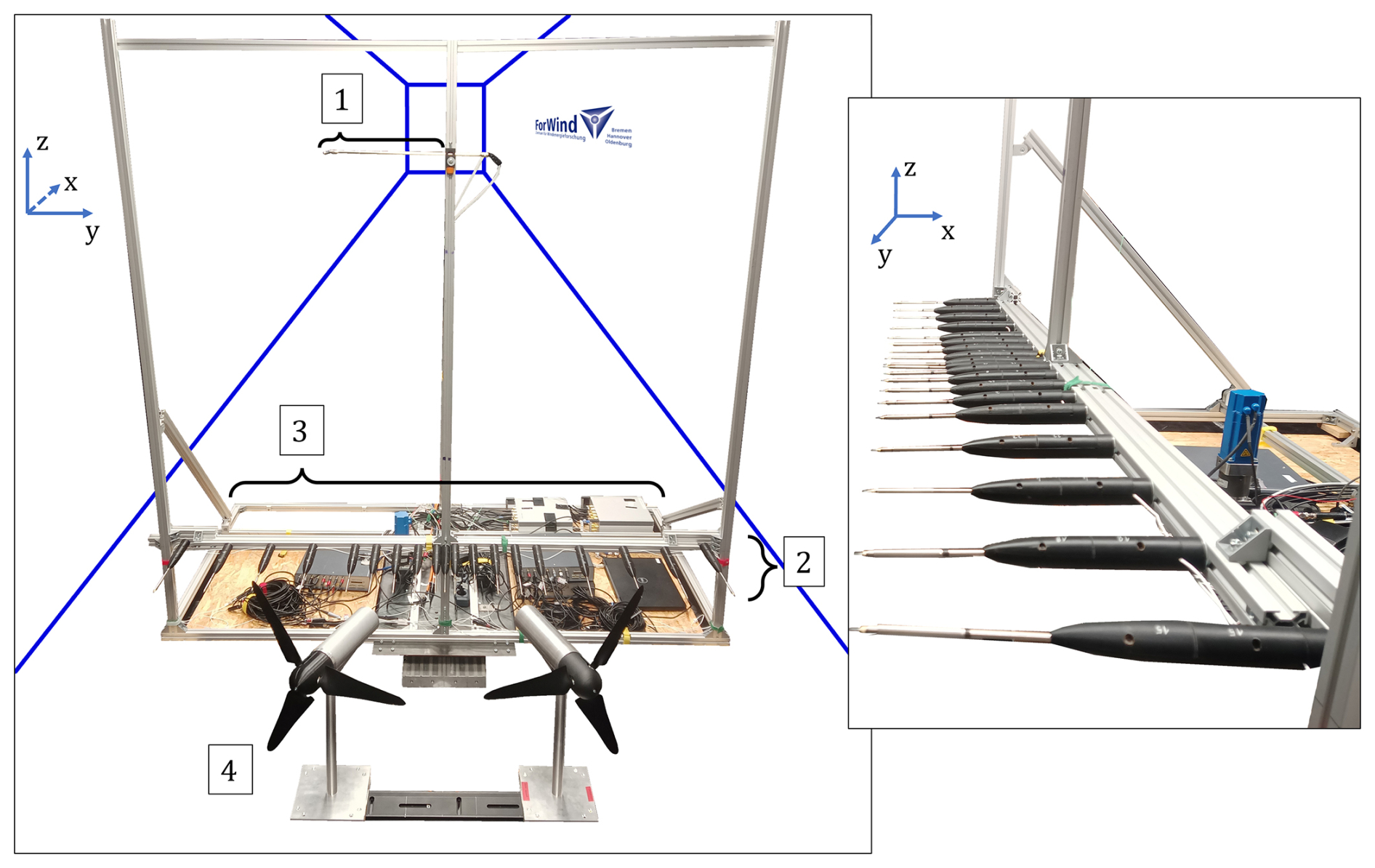
Figure 1Left: experimental setup including (1) a Prandtl tube, (2) hot wires, (3) AD converters, power supply, and mini-CTAs, together with (4) two MoWiTO 0.6 in a yawed configuration. Right: hot-wire probes at hub height in an aerodynamically optimized mount.
Two MoWiTO 0.6 (Model Wind Turbine Oldenburg) with a diameter of 0.58 m served as wake generators. Through utilization of low-Reynolds airfoils, thrust coefficients around cT≈0.8 – comparable to a full-scale turbine – can be achieved (Schottler et al., 2016; Messmer et al., 2023). The turbine is mainly operated by a collective pitch mechanism and a proportional–integral–derivative (PID) controller allowing for an automated generator torque control. An upfront calibration of the PID controller allows for an automated operation even in locally varying inflow conditions in the partial load region of the turbine (Schottler, 2018).
One of the turbines is equipped with clockwise-rotating blades (dyed in blue in all following figures); the other one has counterclockwise-rotating blades (dyed in red in all following figures). Consequently, two major setups will be realized and analyzed in this study: one configuration with the counterclockwise-rotating turbine right of the clockwise-rotating turbine, referred to as “counter-right” (CR), and a second configuration with the counterclockwise-rotating turbine on the left, referred to as “counter-left” (CL). Although different studies by Schottler et al. (2016), Neunaber et al. (2020), and Messmer et al. (2022) have already dealt with and proven the validity of these model turbine wakes and their comparability to full-scale turbine wakes, Sect. 3.1 gives more insight on the parameterization of the individual MoWiTO 0.6 wake.
2.2 Experimental procedure
In preliminary measurements (Maus et al., 2022), it was found that the wake recovery in laminar inflow of the model wind turbine does not change greatly among different wind speeds. Therefore all measurements were taken at a laminar inflow velocity of 5 m s−1, corresponding to the partial load region of the turbine. The hot-wire measurements were taken between 0.75 and 10.0 D downstream of the turbine, and D refers to the turbine diameter of 0.58 m. All lateral and downstream measurement positions can be seen in Fig. 2, with the highest spatial resolution along the centerline. In order to achieve a statistically meaningful number of measurements, the total recording time was set at 240 s at a sampling frequency of 6 kHz, with low-pass filtering at 3 kHz.
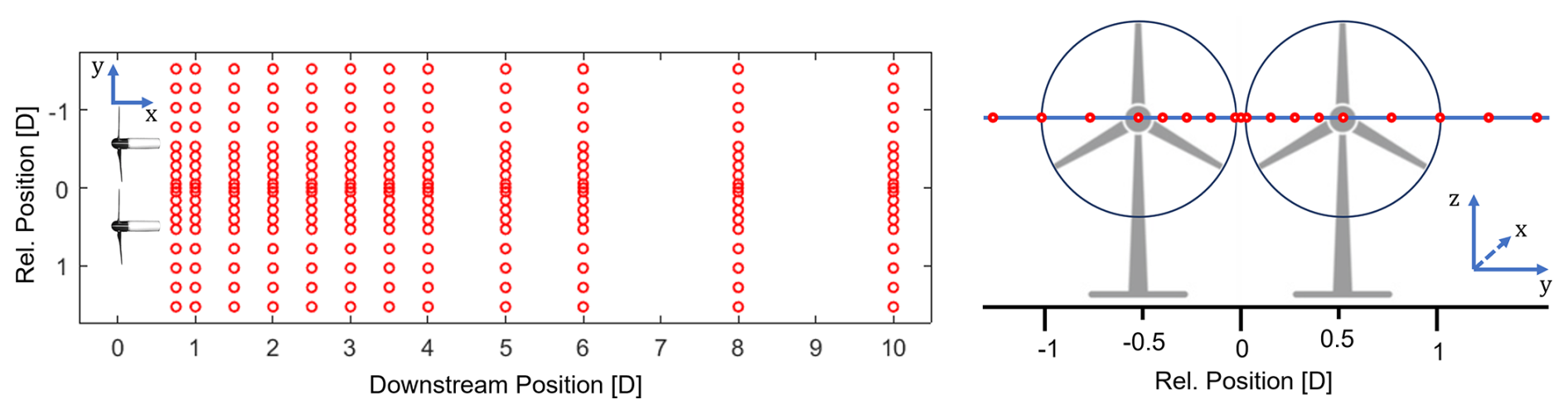
Figure 2Hot-wire measurements were conducted at hub height (illustrated right) across a downstream area ranging from 0.75 to 10 D.
First, both the clockwise and counterclockwise-rotating turbine were analyzed individually in the given setup. This means that only one turbine at a time is placed in the wind tunnel, starting with 0° yaw displacement and then altering between 20, 15, 10, and 5° yaw to the left and to the right, so that in total nine different configurations were realized per turbine.
In the dual-rotor system, the lateral nacelle–nacelle distance between the two turbines was chosen to be 1.07 D for a number of reasons. Previous investigations on the lateral spacing between the turbines showed highest wake–wake interaction below a lateral spacing of 1.15 D (Maus et al., 2022). The closer the turbines were moved together, the more power output of the dual-rotor system was monitored; however, a safety margin of 0.07 D ( 4 cm) had to be maintained to avoid tip collision. Finally, other numerical studies also use similar hub distances of between 1.05 and 1.10 D for a dual- or multi-rotor setup (Speakman et al., 2021; Chasapogiannis et al., 2014; Mendoza et al., 2023).
The different yaw configurations of the two dual-rotor setups counter-left and counter-right were achieved through the following procedure. After the reference case of 0°, the turbines were yawed symmetrically either inward or outward at 5, 10, 15, and 20°, so that nine different alignments were analyzed per rotational configuration (CL or CR).
The following parameters were derived from the data: the normalized wind speed deficit uDef, the turbulent kinetic energy 〈u′2〉, the wake recovery rate Z, and the relative wind velocity in the wake URel:
〈u〉 refers to the time-averaged mean velocity of each hot wire, u0 refers to the reference inflow wind speed in the wind tunnel, u(t) is the measurement time series, and and are two wind speeds at same lateral but different downwind position. URel is the ratio between the average wind speed in the wake (UWake) and the reference wind speed (U0), calculated through the integral of the mean wind velocities over the dual-rotor turbine span from −1.035 to +1.035 D, therefore in the y direction.
The following sections offer a systematic approach to the mechanisms of a dual-rotor wake formation and its possible benefits. In order to break down different steps in the evolution of the wakes and to characterize the interaction between the two turbines, both rotors were measured individually at first. Afterwards, both uDef and the turbulent kinetic energy 〈u′2〉 of the dual-rotor setup will be shown for the different yawed and rotational cases. Finally, the wake recovery and relative wind analysis hint at the most crucial parameters and mechanisms in the dual-rotor setup.
To describe the different cases, the following nomenclature will be used: when describing any setup, the observer's perspective will be looking downwind on the single- or dual-rotor plane. For instance, “yawing the turbines inside” means that both turbines are yawed toward the centerline, and a wake drift to the left means that the wake moves away from the centerline toward the left wall of the wind tunnel, i.e. the upper end in the figures that follow. In addition, the rotational sense is described looking at the turbine in a downwind direction.
3.1 Single-rotor wake
In order to develop a better understanding of the interaction of the individual wakes in the double-rotor configuration, the wakes of the individual turbines are measured first. These data will be used later to explain findings in the behavior of dual-rotor wakes. As a result, both the clockwise and counterclockwise-rotating turbines were placed individually within the wind tunnel, and all considered yaw cases (−20 to +20° at 5° steps) were measured with the setup described in Sect. 2.2. The figures that follow will show 2D surface plots of the normalized wind velocity deficit, calculated in Eq. (1) and the turbulent kinetic energy calculated in Eq. (2) for cases yawed 0° as well as ±20°. All measurement positions are marked with small black dots.
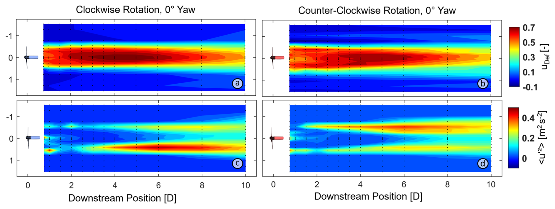
Figure 3Velocity deficit (a, b) and turbulent kinetic energy (c, d) of the clockwise and counterclockwise-rotating single turbine.
In accordance with previous studies (Neunaber, 2019; Schottler et al., 2018), the wake of the non-yawed setup (Fig. 3) shows the highest velocity deficit between 4 and 5 D downstream of the rotor plane. At 8–10 D, the wake widens and the streamwise velocity along the centroid starts to recover for both the clockwise and the counterclockwise-rotating turbine. This relatively slow recovery of the non-yawed case can be mainly attributed to the laminar inflow of the setup. Previous experimental, numerical, and full-scale studies have shown that a low turbulence intensity in the inflow inhibits the entrainment due to an absence of larger turbulent structures and a low lateral kinetic energy flux (Porté-Agel et al., 2020; Cherubini et al., 2022). Furthermore, visualizations of the setup at hand showed relatively far-persisting tip vortices (Maus, 2022), preventing shear stress between wake and free flow, which is necessary for an initiation of the wake recovery.
The first differences between the two different turbines occur when looking at 〈u′2〉. For the clockwise-rotating turbine, the right side of the wake shows an increase in turbulent kinetic energy, whereas for the counterclockwise-rotating turbine, this increase shows as an orange patch on the left side of the wake. A possible explanation for this effect will be given at the end of this section, after also looking at the wakes of both turbines under yawed condition. The velocity deficit of both turbines under positive and negative yaw can be seen in the following Fig. 4.
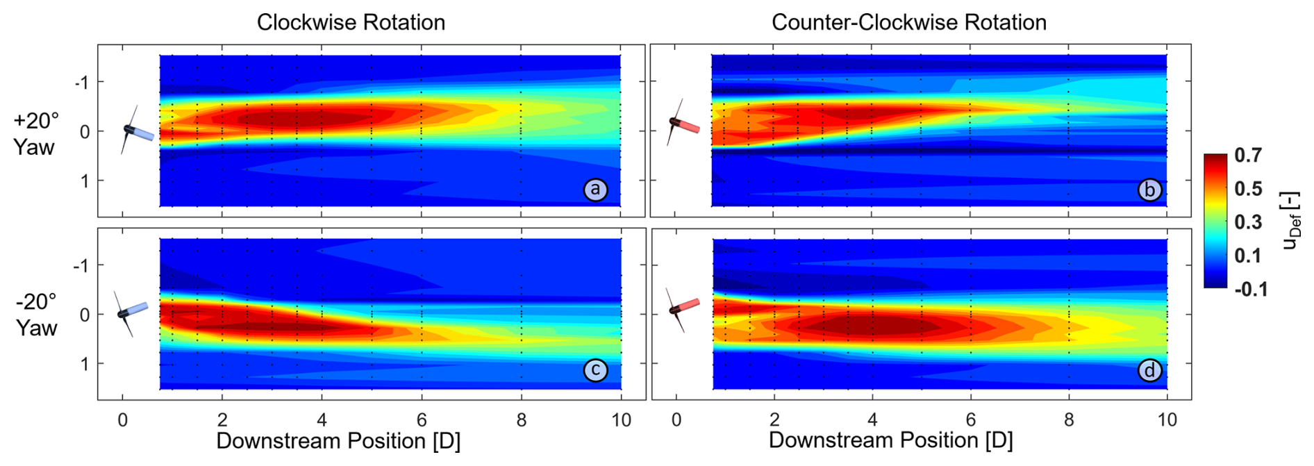
Figure 4Velocity deficit plots of the individual clockwise and counterclockwise-rotating turbines, at a rotor yaw of ±20°.
In contrast to the non-yawed cases, Fig. 4 shows that the highest velocity deficit for a yawed rotor is reached earlier, between 2 and 5 D downstream, and a generally better recovery can be seen. The wake widths at 10 D behind the rotor plane are reduced in comparison to the non-yawed cases (non-yawed: 1.3–1.5 D wake width, yawed: 0.7–1.1 D wake width). In addition, the wake centroid is strongly deflected to the sides; moreover, it can be seen that the degree of wake deflection depends on the rotational sense of the turbine. For instance, the clockwise-rotating turbine deflects the turbine better to its right, whereas the counterclockwise-rotating turbine deflects it better to the left.
In general, the strong wake-center deflection of the yawed rotor can be explained through momentum theory and is a well-known means of wake steering (Jiménez et al., 2010). The fundamental difference in wake intensity and recovery is partly attributed to the fact that due to yawing the turbine, the projected rotor area is lowered and the turbine blades are misaligned to the airflow, therefore less energy is extracted. A more detailed view on the wake recovery follows in Sect. 3.2.3. To understand why the individual wake centroids are deflected unevenly to the left and to the right, depending on their rotational sense, one can take a closer look at the turbulent kinetic energy for the different yawed cases in Fig. 5.
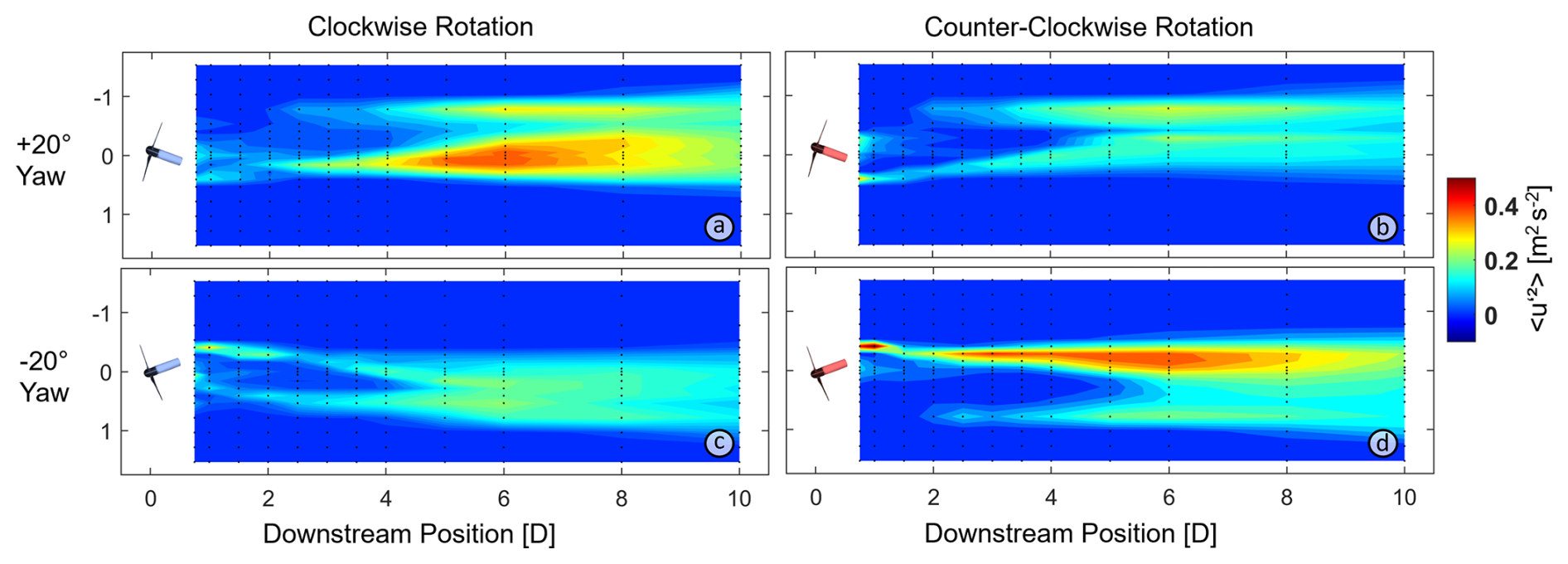
Figure 5Turbulent kinetic energy of the yawed individual clockwise- and counterclockwise-rotating turbines.
When connecting the wake centroid deflection seen in Fig. 4 to the big patches of turbulent kinetic energy in Fig. 3, it becomes clear that the individual wakes are deflected stronger toward the side of the rotor plane that shows higher values of 〈u′2〉 (elongated orange areas in Fig. 3c and d). For the clockwise-rotating turbine, this is the right side and for the counterclockwise-rotating one, it is the left.
For the turbulent kinetic energy in the yawed cases (Fig. 5), this means the following: when the yaw of the individual turbine directs the wake away from the area of high 〈u′2〉, the wake centroid is only deflected slightly and the original space of high 〈u′2〉 remains highly turbulent (Fig. 5a and d). In contrast, a deflection of the rotor wake into the highly turbulent area (Fig. 5b and c) seemingly causes a dissipation of stronger turbulent structures, therefore lower values for the turbulent kinetic energy and a better wake deflection.
An explanation for the higher turbulent kinetic energy on the right (clockwise-rotating rotor) or left (counterclockwise-rotating rotor) is provided by the vertical wake investigations of Pierella and Sætran (2017), who examined the impact of the turbine tower on wake symmetry. Using a five-hole pitot tube, they showed that the tower wake persists downstream and is rotated in the direction of the wake rotation, leading to an asymmetric velocity deficit. Consequently, the asymmetry appears on the right side of a clockwise- and on the left side of a counterclockwise-rotating turbine, particularly when looking at 〈u′2〉 (Fig. 3c and d). It should be noted that, due to scaling limitations, the model turbine tower – and therefore its wake – is relatively larger than that of a full-scale turbine. A schematic of this process for a clockwise-rotating turbine is shown in Fig. 6.
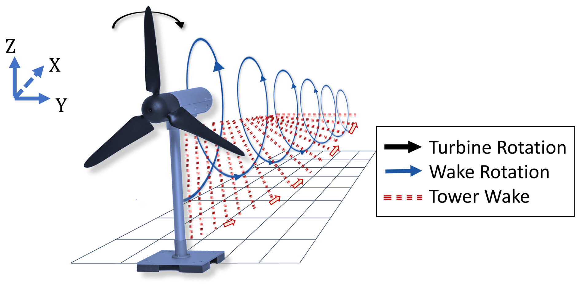
Figure 6Schematic explanation of the interaction of the turbine-induced wake rotation with the tower wake. Owing to the law of conservation of angular momentum, the wake rotates in the opposite direction of the turbine, which draws the tower wake up and into the measurement plane.
As explained above, it was observed that yaw misalignment can direct the turbine wakes stronger toward the side, where the tower wake is drawn into the measurement plane. For instance, yawing the clockwise-rotating turbine to −20° (Fig. 4c) causes two advantageous mechanisms: downstream of the turbine, the wake rotation draws the tower wake to the right outside, allowing for a better mixing of the turbulent wake flow with the surrounding flow. On the left side, the wake rotates downward, so that the free flow from above the turbine is entrained into the wake. Both mechanisms benefit the wake recovery, resulting in a lower velocity deficit compared to the non-yawed condition. Following this, the wake of a clockwise-rotating turbine can be directed much better to the right (and vice versa) for the counterclockwise-rotating turbine. These hypotheses are supported by the 〈u′2〉 contour plots of the rotors in Fig. 5. This is especially important when using actuator disks as a substitution for model wind turbines in future wind tunnel investigations or simulations. Although these disks can achieve very good correlation for thrust, velocity deficit or turbulence values (Howland et al., 2016), an underrepresentation of the important mechanism of wake rotation might lead to different conclusions concerning wake steering through yaw misalignment.
3.2 Dual-rotor wake
3.2.1 Normalized velocity deficit
This section will show to what extent the rotational direction and the yaw affect the wake behind a dual-rotor model. For reference, Fig. 7 shows the two dual-rotor wakes of CR and CL at a non-yawed configuration. A detailed analysis of this setup was previously described in Maus et al. (2022). It was found that the rotational sense has a significant impact on the wake formation behind the dual rotor. The most prominent effect visible in this plot is the difference in wake width at 10 D behind the rotors. Although the CR setup shows nearly no lateral expansion, the wake edges in CL have broadened to about −1.25 to 1.25 D.
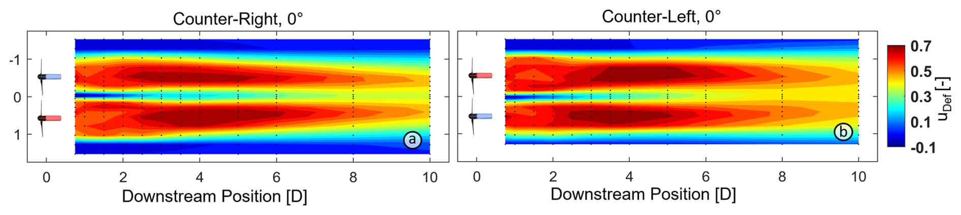
Figure 7Velocity deficit of both possible rotor configurations at 0° yaw. Counterclockwise-rotating turbine in red and clockwise-rotating turbine in blue.
This difference in wake expansion will be promoted to an even greater extent when looking at yawed configurations of the setups. Figure 8 shows both rotational configurations at 20° inward and outward yaw, which are the cases with the strongest yaw displacement investigated in this study.
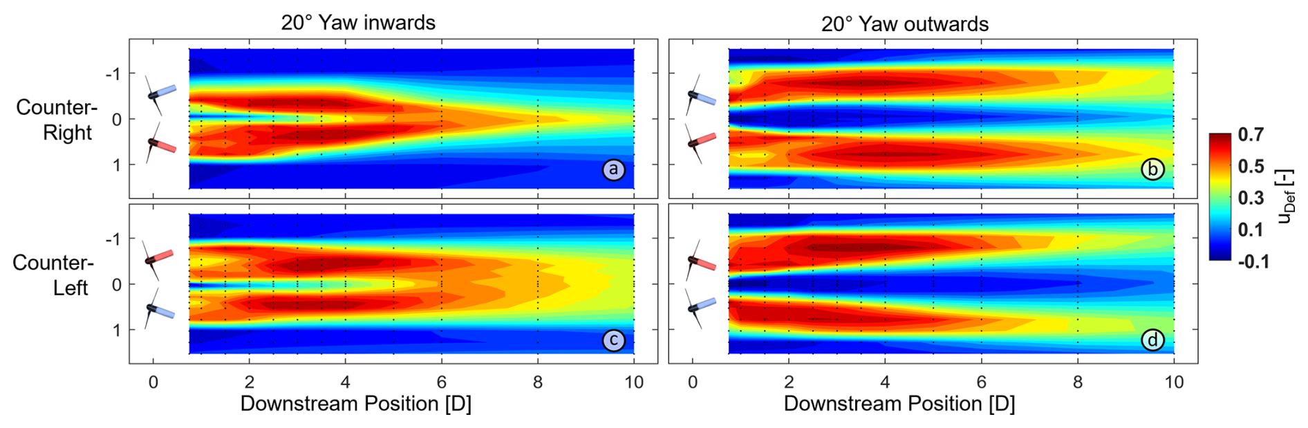
Figure 8Velocity deficit of both possible rotor configurations at 20° inward (a, c) and 20° outward (b, d) yaw. Counterclockwise-rotating turbine in red and clockwise-rotating turbine in blue.
Even at identical yaw and inflow conditions, the impact of the rotational sense is tremendous. In the CR setup with inward yaw (Fig. 8a), the two separate wakes merge very quickly into one very narrow wake, which shows a width of less than 1 turbine diameter at a downstream distance of 6 D. In contrast, the same inward yaw with the counterclockwise-rotating turbine on the left (Fig. 8c) only causes the two rather individual wakes to merge about 4 D behind the rotor, forming a very stable and uniform wake with an approximate width of 2 D, even 10 D downstream.
Yawing both rotors outward causes a split of the dual-rotor wake into two separate individual wakes (Fig. 8b and d). Although the wake similarity of CR and CL for 20° outward yaw is greater than for the inward case, a couple of differences can be pointed out. First of all, the single-wake centroids in the CR setup follow a rather straight line in a downwind direction. In contrast, the wakes in CL are persistently drifting outward and the inter-wake space is growing. At 10 D, the wakes in the CR setup meet at the centerline, whereas no wake merging can be observed for CL within the measurement frame. Finally, the normalized velocity deficit of the single wakes in CL have recovered to below 0.5 (orange surface) about 2 D faster than in CR.
In the case of CR yawed 20° inward, the wakes rotate in such a manner that the tower wake is entrained toward the inside of the dual-rotor wake. Following this, the outer wake edges, which are forced toward the centerline because of momentum theory, have a large area of interaction with the surrounding freestream, so that uniform flow is entrained into the measurement plane at the wake edges. These mechanisms cause a very narrow residual wake at 8–10 D downstream. In the case of CL yawed 20° outward, the same mechanisms can account for the strong separation of the two individual wakes. Here the undisturbed flow is entrained toward the centerline by the wake rotations of both turbines. For instance, the counterclockwise-rotating turbine with its clockwise-rotating wake pulls the tower wake to the outside of the setup, where the interface between free flow and turbine wake is at a maximum, resulting in a faster wake decay.
3.2.2 Turbulent kinetic energy
In order to validate the theory of the wake rotation drawing the tower wake into the measurement plane, the turbulent kinetic energy can be used to identify added turbulence and to highlight important transition regions, which are not visible in the normalized wind speed deficit.
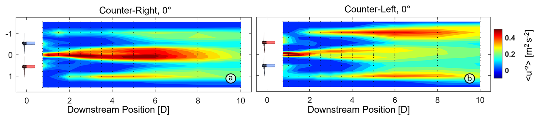
Figure 9Turbulent kinetic energy of both rotor configurations without yaw (counterclockwise-rotating turbine in red and clockwise-rotating turbine in blue).
For reference, Fig. 9 shows both configurations at 0° turbine yaw. Despite only minor differences between the wake width in both setups in Fig. 7, the analysis of turbulent kinetic energy reveals stronger differences between the two configurations. Although the strongest fluctuations for both setups are found along the centerline and at the edges of the dual-rotor wake, CR (Fig. 9a) shows its high values of 〈u′2〉 mostly along the centerline, whereas CL (Fig. 9b) only has very high 〈u′2〉 values in the very near wake at the centerline and otherwise shows higher values alongside the outer wake edges between 4 and 8 D downstream. This can again be attributed to the influence of the wake rotation and the tower wake presented in Sect. 3.1 for the individual rotors.
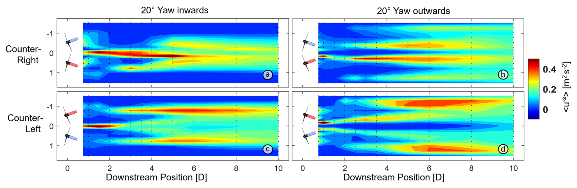
Figure 10Turbulent kinetic energy of both rotor configurations at 20° inward (a, c) and 20° outward (b, d) yaw (counterclockwise-rotating turbine in red and clockwise-rotating turbine in blue).
In Fig. 10, the near wakes of the individual rotors in the dual-rotor setup between 1.5 and 3.5 D show an area of relatively low turbulence. However, the transition regions in between the individual rotor wakes (along the centerline of the setup), as well as the outside of the wakes, show very different and unique properties and must be discussed individually.
In Fig. 10a, with CR at a 20° inward yaw, the highest 〈u′2〉 values are found along the centerline of the dual rotor between 1 and 6 D downstream. CL with a 20° inward yaw (Fig. 10c) also shows extreme turbulence along the centerline between 1 and 2.5 D; however, then the wake field becomes – from the horizontal perspective investigated here – relatively isotropic, and only the outer edges are marked by higher turbulent kinetic energy. The turbulence field of the outward yaw confirms what has been stated before: in Fig. 10b, the wakes of CR start to interact and mix between 8 and 10 D downstream, whereas CL maintains a complete separation not only in wind velocity but also in turbulence – see Fig. 10d. Clusters of strongest wind fluctuations are found along the edges of the single wakes between 3 and 8 D – for CR especially the inner wake edges and for CL the outer wake edges.
The two main drivers of high turbulence in the MoWiTO 0.6 wake are the tip-vortex breakdown and the mixture of tower with rotor wake. In those cases, where both rotors are yawed inward, the small lateral distance and the deflection of the rotor wakes toward one another cause a very early mixing of the tip vortices. The sudden breakdown shows as a localized area with very high turbulent kinetic energy along the centerline for both CL and CR. Whereas the wake evolves into a relatively homogeneous wake for CL, the high 〈u′2〉 remains for CR. This can be attributed to the fact that after the tip vortices have broken down, the wake has progressed far enough downstream to show the interaction of tower with rotor wake. The rotation has entrained the turbulent structures into the measurement plane, and the decay shows as area of high turbulent kinetic energy. In CR and inward yaw, this shows as a persistently high all the way until 8 D, as the tower wakes of both turbines overlap and mix in this area. In the outward yaw, the individual wakes have not yet mixed at 4–7 D, but the mixture of tower and rotor wake can account for the wake widening and mixing further downstream in the outward yaw setup.
In the two different CL setups, the wake rotation causes the tower shadow and its turbulent decay to show along the outside of the dual-rotor wake as an orange stripe. This is the main driver for the strong wake centroid deflection in CL 20° outward yaw (see Fig. 8). The entrainment to the inside of the dual rotor helps to keep the wakes separate or, on the inward yaw case, supports the formation of a relatively large isotropic turbulent field along the centerline of the rotor setup. For completeness, the presented correlations and explanations remain valid for all intermediate setups (5, 10, and 15° inward and outward yaw); however, due to the best representation, only the extreme cases with 20° inward and outward yaw misalignment are shown here.
3.2.3 Wake recovery
In order to evaluate the benefit of yawing the turbine-configurations inside or outside, the wake recovery rate Z has been calculated through Eq. (3), which mathematically corresponds to the streamwise derivative of the wind speed. A negative value means a deceleration of the flow and a buildup of the wake, and a positive value attributes to the actual decay and recovery of the wake.
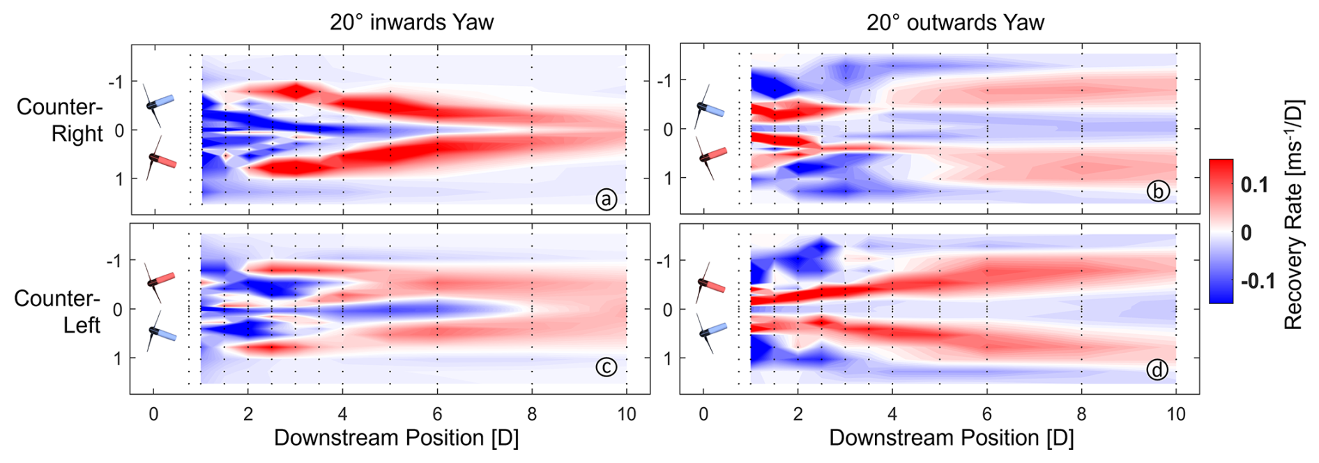
Figure 11Streamwise recovery rate of both rotor configurations at 20° inward (a, c) and 20° outward (b, d) yaw (counterclockwise-rotating turbine in red and clockwise-rotating turbine in blue; actual wake recovery dyed red and wake buildup colored in blue).
It is important to note that Fig. 11 shows the overall wake recovery rate in streamwise direction, not lateral or wake centroid direction. Because of the turbine yaw, the wakes not only evolve in downstream direction but are deflected sideways, which shows as the yellow area in the surface plots.
In general, it can be observed that in the near wake, between 1 and 3 D downstream of the dual rotor, many mechanisms of wake formation seem to overlay, causing an area with numerous small patches of both strong recovery or buildup. This can be attributed to the pressure difference trying to balance between free flow and rotor shadow (Boudreau and Dumas, 2017). Further downwind, the structures start to form larger patches and the wakes mostly start to recover. Only in Fig. 11c, a larger dark-green area along the centerline between 4 and 7 D hints at a secondary wake-buildup. Apparently, this is where the collision of the two individual wakes and mixing of their tip vortices causes a further deceleration of the flow, unusually far behind the rotor plane.
The two cases with the most outstanding wake recovery rates are CR at 20° inward yaw and CL at 20° outward yaw (Fig. 11a and d). Owing to a strong wake deflection either into (CR, 20° inward) or away from each other (CL, 20° outward), the flow downwind of the dual rotor is able to recover quickly, with highest recovery rates between approximately 2.5 and 6 D. This makes its application highly appealing for use in wind farms, where numerous turbines are positioned closely together and rapid flow recovery is essential.
When coupling the recovery rate to the rotational direction of the rotor, a faster recovery is always found on that side of the turbine, where the blades move in an upward direction. As the wake rotates in the opposite direction as the rotor, this finding proves the relevance of flow entrainment from above the turbines for the wake recovery. As the wake rotates in a downward direction, the flow from above the turbine is pulled into the measurement plane, accelerating the recovery of the wake.
In order to quantify the benefit on wake recovery through yaw misalignment, Eq. (4) has been introduced. It integrates the wind velocity over the span of the dual rotor and relates it to the reference inflow wind speed. Instead of showing the spatial distribution and explaining different mechanisms or wake artefacts, this method allows a comparison of all investigated rotational and yaw cases in one graph. It summarizes the quality of the dual-rotor wake recovery and quantifies how much relative wind a turbine, positioned downwind of the first turbine, has available. To do this, the integration boundaries are set to −1.035–1.035 D, which corresponds to the span of the dual rotor.
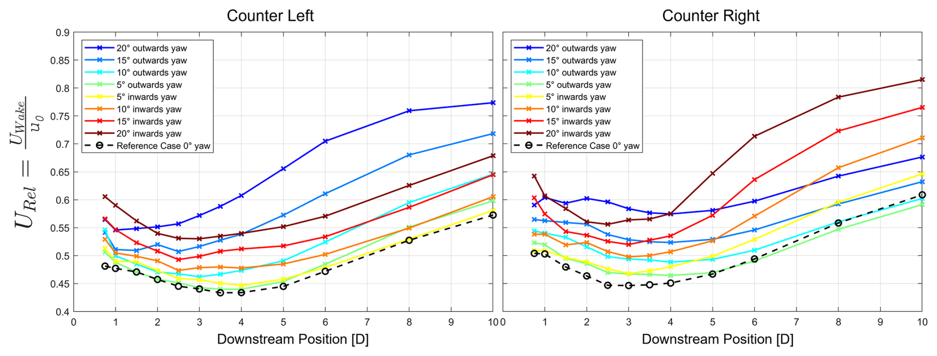
Figure 12Line plots of the wind in the wake of a dual rotor, relative to the inflow. A value of URel=1 would correspond to a fully recovered velocity deficit.
Figure 12 shows the downstream evolution of the relative average wind velocity in the wake of the investigated dual-rotor turbine for all different yaw configurations and both rotational settings. In these plots, a value of URel=1 would correspond to a fully recovered flow and URel=0 would mean a stagnation of the flow.
The reference case (dashed black line) shows the relative wind speed – as introduced in Eq. (5) – in the wake of a dual rotor with 0° yaw of the single turbines. In both cases (CR and CL), the relative wind speed drops until a few D downstream, followed by its recovery. This behavior, as mentioned earlier, is explained by the time it takes the pressure difference to balance between the surrounding flow and the near wake of each rotor (Boudreau and Dumas, 2017; Sanderse, 2009). After the pressure gradient has been overcome, energy is entrained from the surrounding flow through turbulent mixing and the wakes start to recover, resulting in an upward trend of the lines in Fig. 12.
Both in CL and in CR, nearly all investigated cases follow the previously described principle, only that in some setups, the recovery either starts earlier or is generally better than in the reference case. Taking a closer look at the CL setup in Fig. 12, one can observe that the point where the wake starts to recover (i.e. the lowest point of the curve) moves closer to the turbine, as the yaw misalignment is increased. The most extreme example is the relative wind speed in the wake in a 20° outward yaw (Fig. 12, left, dark-blue line), which only drops until 1 D downstream and immediately starts to increase afterward. This curve is marked not only by one of the earliest starts but also by one of the fastest rates of recovery, reflected by the slope of the curve. Both factors result in the best relative wind speed in the CL setup at 10 D downstream, with URel>0.75.
For the CR setup (Fig. 12, right), the earliest start of wake recovery and the fastest recovery rate is seen in the 20° inward yaw, with a relative wind speed of more than 0.8 at the end of the measurement plane (10 D). Even though the outward yaw yields an overall faster relative flow at 10 D than the reference case, the start of the recovery is delayed until 4–5 D and the rate of recovery is moderate.
The difference in the recovery of the relative wind speed behind the different setups needs to be discussed separately between CR and CL. The earliest start of wake recovery for CR is found at the inward yaw, therefore directing the wakes into each other. In other studies it has already been found that tip-vortex instability is of great relevance for the recovery of a wake (Lignarolo et al., 2014). As the forced trajectory of the wakes trigger a quick collision and thus enhance the tip-vortex instability around a wake, a faster energy flux from the surrounding flow into the near wake is enabled and a quicker recovery can be seen.
For the CL outward setup, it is useful to look at the findings of the single wake deflection (Sect. 3.1). It was found that the wake of a rotating turbine is deflected easier to the side, where the blades rotate in a downward motion and recover better on the side with blades in an upward motion. For the CL setup, this is the case on the inside, along the centerline of the setup. The individual wakes are then directed strongly away from each other, causing the flow above the turbines to fill the low-pressure field in between the turbines and therefore resulting in the highest relative wind speed downstream of the turbines and the fastest wake recovery.
In summary, nearly all yawed configurations yielded a better flow recovery than a dual rotor without yaw. This can be explained by either having a much quicker wake recovery caused by self-induced tip-vortex instability through wake collision or by directing the trajectory of the wakes away from a possible downwind turbine and accelerating the entrainment from above. In terms of overall ensemble- or wind farm efficiency, it must be said that the misalignment of the rotors of the dual rotor caused a relative power drop of 12.6 ± 1.6 % when comparing the 20° yawed setups to the non-yawed case. Even though these scaled experimental investigations cannot perfectly reflect the behavior of real wind turbines – mainly due to restrictions in reaching full-scale power coefficients – the results hint at a very promising way to mitigate wake effects for downstream turbines and increase wind farm efficiency. In order to draw more precise conclusions on ensemble efficiency, further investigations with more than one dual rotor – either experimentally or numerically – will become necessary.
This study presents an experimental approach to characterize the wake evolution and interaction behind a dual-rotor turbine with counter-rotating rotors in dependency of the respective yaw. In order to achieve that, two MoWiTO 0.6 were positioned in a wind tunnel at a lateral hub–hub distance of 1.07 D. Their yaw was alternated between a mirror symmetrical outward and inward yaw of 20° at a step size of 5°, so that in total nine different yaw setups were investigated for each of the two rotational cases (CR and CL). The wake was monitored through a hot-wire array, which traversed between 0.75 and 10 D behind the turbines.
In order to have a baseline behavior of the individual rotors, both the wake of the clockwise- and counterclockwise-rotating turbine were investigated individually in dependency of their yaw. In these preceding experiments, it was already observed that the wake steering of a turbine is greatly dependent on the rotational sense of the setup. It was found that a wake is much easier deflected to the side, where blades move in a downward direction and the wake, as it is rotating in the opposite direction of the blades, in upward direction. For the clockwise-rotating case, this means a deflection to the right is enhanced and vice versa for a counterclockwise-rotating individual turbine.
After arranging the turbines in the dual-rotor configuration, this effect could be transferred to the two different rotational configurations. It was easier to deflect the rotor wakes toward the centerline, when the clockwise-rotating turbine was positioned left. The strongest split of the individual rotor wake was achieved by operating the clockwise-rotating turbine on the right. The underlying mechanism for this was found to be the rotating wake interacting with the tower wake on the one side and the free undisturbed flow on the other side. It is suggested that the tower wake, when drawn into the measurement plane, decelerates and widens the wake; meanwhile, on the other side, an entrainment of free undisturbed flow from above the rotor accelerates the recovery.
These findings are supported by the profiles of turbulent kinetic energy, where, under the concept of added turbulence, those regions of the wakes show the strongest fluctuations – where the tower wake gets drawn into the measurement plane. It was shown that when yawed inward, the colliding tip vortices of both rotor wakes in combination with the tower wakes generate an extremely turbulent field along the centerline, followed by a quick wake recovery.
Finally, an analysis of the relative wind velocity in the wake showed that almost all rotational and yaw configurations yielded a better recovery of the wake than the reference case of 0° yaw. The two predominant factors for that were found to either be the outward centroid deflection (away from a possible downwind turbine) or a faster interaction of the turbulent wakes. As found in literature (Lignarolo et al., 2015), the tip-vortex stability plays a fundamental role in the decay and recovery of a wind turbine wake. As a result, the direction of two wakes into each other can trigger an accelerated vortex breakdown and contributes to a faster recovery.
For a future possible implementation of dual rotors in a wind park, these findings demonstrated possible gains for the turbines in the second or third row. The ease of directing the wakes either apart (for an enhanced flow entrainment from above) or into each other (to target tip-vortex instability) are two possible paths to increase the overall power output of the wind farm. Furthermore, the effect of higher turbulence or a sheared inflow to the dual rotor, as expected in real applications, can be of great relevance. A more turbulent flow would lead to a faster wake recovery in the first place, due to faster tip-vortex breakdown and turbulent energy entrainment into the wake. The influence of sheared inflow could be a bit more complex. As presented in the example of the trajectory of the tower wake being drawn with the wake rotation, a vertical shear could possibly follow similar behavior. Being drawn with the wake rotation could increase the energy entrainment on that side with a higher local flow velocity – for example, above the rotor – or increase the velocity deficit when a lower local velocity is superimposed onto the rotor wake.
All in all, it was found that the lateral interaction of wakes is a complex three-dimensional mechanism. Consequently, further investigations in the vertical axis and with more turbulent or sheared wind fields will clarify how far the concepts can be applied below or above hub height.
The data that support the findings of this study are available in the data repository of Maus (2026) (https://doi.org/10.57782/DNWQIO).
In the scientific process, JM developed the methodology in close contact with MH. The investigation, formal analysis, visualization, and writing (original draft) was performed by JM. The initial concept, resources, supervision, and project administration was provided by MH, in addition to reviewing and curating the paper drafts. JP contributed in a supervisory role.
At least one of the (co-)authors is a member of the editorial board of Wind Energy Science. The peer-review process was guided by an independent editor, and the authors also have no other competing interests to declare.
Publisher's note: Copernicus Publications remains neutral with regard to jurisdictional claims made in the text, published maps, institutional affiliations, or any other geographical representation in this paper. The authors bear the ultimate responsibility for providing appropriate place names. Views expressed in the text are those of the authors and do not necessarily reflect the views of the publisher.
The author would like to thank all colleagues of ForWind, University of Oldenburg, for helping hands, fruitful discussions, and assistance during and after the measurements. We would like to especially thank Julian Jüchter for the development and help with the MoWiTO 0.6.
This paper was edited by Jan-Willem van Wingerden and reviewed by two anonymous referees.
Bastankhah, M. and Porté-Agel, F.: Wind farm power optimization via yaw angle control: A wind tunnel study, J. Renew. Sustain. Ener., 11, https://doi.org/10.1063/1.5077038, 2019. a, b, c
Boudreau, M. and Dumas, G.: Comparison of the wake recovery of the axial-flow and cross-flow turbine concepts, J. Wind Eng. Ind. Aerod., 165, 137–152, https://doi.org/10.1016/j.jweia.2017.03.010, 2017. a, b
Chasapogiannis, P., Prospathopoulos, J. M., Voutsinas, S. G., and Chaviaropoulos, T. K.: Analysis of the aerodynamic performance of the multi-rotor concept, J. Phys. Conf. Ser., 524, 012084, https://doi.org/10.1088/1742-6596/524/1/012084, 2014. a, b
Cherubini, S., Cillis, G. D., Semeraro, O., Leonardi, S., and Palma, P. D.: How incoming turbulence affects wake recovery of an NREL-5MW wind turbine, J. Phys. Conf. Ser., 2385, 012139, https://doi.org/10.1088/1742-6596/2385/1/012139, 2022. a
EnBW and Aerodyn: Floating wind turbine: Nezzy², https://www.enbw.com/renewable-energy/wind-energy/our-offshore-wind-farms/nezzy2-floating-wind-turbine/ (last access: 15 July 2026), 2021. a
Ge, M. and Friedrich, J.: Greenhouse gas emissions by countries and sectors, https://www.wri.org/blog/2020/02/greenhouse-gas-emissions-by-country-sector (last access: 15 July 2026), 2020. a
Ghaisas, N. S., Ghate, A. S., and Lele, S. K.: Effect of tip spacing, thrust coefficient and turbine spacing in multi-rotor wind turbines and farms, Wind Energ. Sci., 5, 51–72, https://doi.org/10.5194/wes-5-51-2020, 2020. a
Howland, M. F., Bossuyt, J., Martínez-Tossas, L. A., Meyers, J., and Meneveau, C.: Wake structure in actuator disk models of wind turbines in yaw under uniform inflow conditions, J. Renew. Sustain. Ener., 8, 4, https://doi.org/10.1063/1.4955091, 2016. a
Jiménez, Á., Crespo, A., and Migoya, E.: Application of a LES technique to characterize the wake deflection of a wind turbine in yaw, Wind Energy, 13, 559–572, https://doi.org/10.1002/WE.380, 2010. a
Lignarolo, L. E., Ragni, D., Krishnaswami, C., Chen, Q., Simão Ferreira, C. J., and van Bussel, G. J.: Experimental analysis of the wake of a horizontal-axis wind-turbine model, Renew. Energ., 70, 31–46, https://doi.org/10.1016/j.renene.2014.01.020, 2014. a
Lignarolo, L. E., Ragni, D., Scarano, F., Simão Ferreira, C. J., and Van Bussel, G. J.: Tip-vortex instability and turbulent mixing in wind-turbine wakes, J. Fluid Mech., 781, 467–493, https://doi.org/10.1017/jfm.2015.470, 2015. a
Maus, J.: Tip-Vortex Slow Motion – Model Wind Turbine Oldenburg, YouTube, https://www.youtube.com/shorts/tMZ9C_ui_bQ (last access: 15 July 2026), 2022. a
Maus, J.: Wake Interactions in a Counterrotating Dual Rotor System: Experimental HW-Measurements, Carl von Ossietzky Universität Oldenburg [data set], https://doi.org/10.57782/DNWQIO, 2026. a
Maus, J., Peinke, J., and Hölling, M.: Experimental investigation on the effect of lateral turbine spacing on interactions of wakes, J. Phys. Conf. Ser., 2265, 042064, https://doi.org/10.1088/1742-6596/2265/4/042064, 2022. a, b, c, d, e
Memija, A.: China's Mingyang unveils plans for massive 50 MW floating wind turbine, https://www.offshorewind.biz/2025/10/21/chinas-mingyang-unveils-plans-for-massive-50-mw-floating-wind-turbine/ (last access: 15 July 2026), 2025. a
Mendoza, V., Katsidoniotaki, E., Florentiades, M., Dot Fraga, J., and Dyachuk, E.: Aerodynamic performance of a dual turbine concept characterized by a relatively close distance between rotors, Wind Energy, 26, 521–537, https://doi.org/10.1002/we.2813, 2023. a, b, c
Messmer, T., Brigden, C., Peinke, J., and Hölling, M.: A six degree-of-freedom set-up for wind tunnel testing of floating wind turbines, TORQUE 2022) J. Phys. Conf. Ser., 2265, 42015, https://doi.org/10.1088/1742-6596/2265/4/042015, 2022. a
Messmer, T., Hölling, M., and Peinke, J.: Enhanced recovery and non-linear dynamics in the wake of a model floating offshore wind turbine submitted to side-to-side and fore-aft motion, arxiv [preprint], https://doi.org/10.48550/arXiv.2305.12247, 2023. a
Neunaber, I.: Stochastic investigation of the evolution of small-scale turbulence in the wake of a wind turbine exposed to different inflow conditions, Dissertation, University of Oldenburg, https://oops.uni-oldenburg.de/id/eprint/3852 (last access: 15 July 2026), 2019. a
Neunaber, I., Hölling, M., Stevens, R. J., Schepers, G., and Peinke, J.: Distinct turbulent regions in the wake of a wind turbine and their inflow-dependent locations: The creation of a wake map, Energies, 13, 5392, https://doi.org/10.3390/en13205392, 2020. a
Newell, R. G., Raimi, D., and Aldana, G.: Global energy outlook 2019: The next generation of energy, Resources for the future, p. 46, https://www.rff.org/publications/reports/global-energy-outlook-2019/ (last access: 15 July 2026), 2019. a
Pierella, F. and Sætran, L.: Wind tunnel investigation on the effect of the turbine tower on wind turbines wake symmetry, Wind Energy, 20, 1753–1769, https://doi.org/10.1002/WE.2120, 2017. a
Porté-Agel, F., Bastankhah, M., and Shamsoddin, S.: Wind-turbine and wind-farm flows: A review, vol. 174, Springer Netherlands, ISBN 1054601900473, https://doi.org/10.1007/s10546-019-00473-0, 2020. a
Sanderse, B.: Aerodynamics of wind turbine wakes: Literature review, Energy Research Centre of the Netherlands, 1–46, https://repository.tno.nl/SingleDoc?find=UID 9f4dd67d-5fe2-4e86-b2b3-497852de4ea7 (last access: 15 July 2026), 2009. a
Sandhu, N. S. and Chanana, S.: Performance and economic analysis of multi-rotor wind turbine, EMITTER International Journal of Engineering Technology, 6, 289–316, https://emitter.pens.ac.id/index.php/emitter/article/view/298 (last access: 15 July 2026), 2018. a
Schottler, J.: Experimental investigation of wind farm effects using model wind turbines, Dissertation, University of Oldenburg, ISBN 978-3-8440-6027-0, 2018. a
Schottler, J., Hölling, A., Peinke, J., and Hölling, M.: Design and implementation of a controllable model wind turbine for experimental studies, J. Phys. Conf. Ser., 753, https://doi.org/10.1088/1742-6596/753/7/072030, 2016. a, b
Schottler, J., Bartl, J., Mühle, F., Sætran, L., Peinke, J., and Hölling, M.: Wind tunnel experiments on wind turbine wakes in yaw: redefining the wake width, Wind Energ. Sci., 3, 257–273, https://doi.org/10.5194/wes-3-257-2018, 2018. a
Speakman, G. A., Abkar, M., Martínez-Tossas, L. A., and Bastankhah, M.: Wake steering of multirotor wind turbines: a new wind farm control strategy, Phys. Fluids, 1–20, https://doi.org/10.1002/we.2633, 2021. a, b, c
Van Der Laan, M. P. and Abkar, M.: Improved energy production of multi-rotor wind farms, J. Phys. Conf. Ser., 1256, 012011, https://doi.org/10.1088/1742-6596/1256/1/012011, 2019. a, b
Wu, Y. T. and Porté-Agel, F.: Large-eddy simulation of wind-turbine Wakes: evaluation of turbine parametrisations, Bound.-Lay. Meteorol., 138, 345–366, https://doi.org/10.1007/s10546-010-9569-x, 2011. a