the Creative Commons Attribution 4.0 License.
the Creative Commons Attribution 4.0 License.
 | 19 Mar 2026
Development of a hardware-in-the-loop wind tunnel setup to study the aerodynamic response of floating offshore wind turbines
Axelle Viré
In floating wind turbines, wind and wave excitation leads to motions of the floater that affect the rotor aerodynamic loads, which in turn influence the motion of the floater, in a highly coupled way. Numerical design tools can sometimes fail to predict certain aerodynamic phenomena, and therefore experimental testing is essential for tuning and validating these codes. Hybrid testing in wind tunnels, by measuring aerodynamic loads on a physical scale rotor under high-quality wind while numerically reproducing and actuating the floater motions, allows for higher fidelity in the reproduction of the aerodynamics compared to traditional wave basin tests. This work presents the development of a hybrid hardware-in-the-loop setup designed to study the aerodynamic response of floating wind turbines in wind tunnels. A scale model of a multi-megawatt floating wind turbine is mounted on top of a 6-degree-of-freedom hexapod robot. The full coupling of aerodynamic and floater dynamics is obtained with a hardware-in-the-loop approach with force-feedback–motion-actuation architecture. The rotor loads measured on the physical rotor are fed into a floater numerical simulator, which calculates the motion in real time and actuates it through the hexapod. Key outcomes include the development of a hardware-in-the-loop numerical model with an aerodynamic load estimation method to cope with scaling effects and the assessment of the floater simulator, the force estimation, and the measurement-actuation chain. The aerodynamic effects on the motion response are preliminarily investigated on a 10 MW floating concept, allowing the increase in pitch, yaw, and surge damping to be quantified through measured loads. The capability of testing combined wind and wave cases is also demonstrated, setting the framework for future studies.
- Article
(9993 KB) - Full-text XML
- BibTeX
- EndNote


Offshore wind turbines are mostly installed as bottom-fixed structures rigidly mounted on the seabed or moored to the seabed using floating support structures. In waters exceeding 60 m in depth, floating turbines anchored on the seabed are more economical (van Kuik et al., 2016). As suitable shallow-water sites become increasingly scarce, floating offshore wind turbines (FOWTs) offer a promising alternative, unlocking the potential to harness vast wind resources in deeper seas and opening new opportunities in countries without shallow seas.
FOWTs experience (rigid-body) motions in 6 degrees of freedom (DOFs). The floating nature of the wind turbine makes it susceptible to various excitations, including changes in met-ocean conditions, interactions between the wakes and the turbine, and the operation of the turbine itself. The aerodynamic performance of FOWTs is affected by these motions, with the aerodynamic loads acting on the rotor being highly coupled with the floater dynamics. In some cases, unsteady aerodynamic effects are observed due to the interaction of the wind turbine blades with their own wake. These complex interactions are often not yet fully understood. Current state-of-the-art is mostly limited to the analysis of a couple of degrees of freedom of the system under simplified met-ocean conditions.
It is currently challenging to numerically predict the flow physics around and behind floating rotors under certain conditions. The blade-element momentum theory is the reference engineering method to assess the performance of wind turbines. Despite the fact that corrections for rotor unsteadiness exist and have been successfully applied to the case of floating turbines (Papi et al., 2024), this low-fidelity approach cannot yet predict effects such as flow reversal and its impact on the rotor. Higher-fidelity methods, such as the free vortex wake model or computational fluid dynamics (CFD) method, have looked at both rotor unsteady loads and wakes, including returning wake effects (Schulz et al., 2024; Dong and Viré, 2022). However, some discrepancies between the results of high-fidelity numerical models and experimental data were recently found in predicting unsteady loads (Taruffi et al., 2024b). Additionally, the results from an experimental test were compared with the quasi-static theory, which failed to predict the unsteady aerodynamic loading at high frequency (Taruffi et al., 2024a). This shows the need to better understand the unsteady phenomena associated with floating motions and derive more accurate tools for the design of FOWTs.
Experimental testing provides an effective way to investigate these complex phenomena and tune the numerical models. Full-scale testing or large-scale model testing can be done at sea. This was done by Viselli et al. (2015) with a 1:8 FOWT in the Gulf of Maine and by Ruzzo et al. (2021) with a 1:15 floating multi-purpose platform including a wind turbine. However, this is expensive, and real offshore conditions are difficult to reproduce numerically. Hence laboratory tests with scaled models, which allow for a controlled testing environment, are often preferred. Testing FOWTs is traditionally done in a wave basin with Froude scaling. This allows for accurate hydrodynamic load reproduction, enabling an understanding of floater hydrodynamics. For example, Cermelli et al. (2010) studied the hydrodynamics of a 1:67 scaled FOWT in a wave basin with Froude scaling to validate a numerical model. In order to include aerodynamic loading, wind generators with thrust discs or geometrically scaled blades were used to emulate the aerodynamic thrust force on the rotor. These methods successfully generated an aerodynamic thrust force but did not match the values of the full-scale model. The study by Goupee et al. (2014b), which involved testing a 5 MW wind turbine with different floaters in a wave basin with geometrically scaled blades, revealed their drawbacks. This is due to the use of the Froude scaling law that does not allow for reproducing the aerodynamic forces correctly (Robertson et al., 2013). A Reynolds' similarity law would allow for accurate representation of the aerodynamics, but it compromises the gravity-related hydrodynamic loads and anyway leads to impossibly high wind speeds. This scaling law conflict is unavoidable in fully physical wave basin scale tests. To alleviate it, later studies followed a performance-based scaling methodology for the rotor to reproduce aerodynamic thrust more accurately while keeping the Froude scaling (Goupee et al., 2014a; Zhao et al., 2018; Doisenbant et al., 2018). Bredmose et al. (2017) also investigated different control strategies in similar tests. However, this approach still has limitations, the main one being that the wind generators produce low-quality wind flows.
Hybrid testing can overcome these challenges (Shi et al., 2023). Instead of physically applying both the aerodynamic and the hydrodynamic loading, one part is physically tested, while the other is numerically simulated, effectively mitigating the scaling conflict and allowing each part to be tested in the most appropriate laboratory. This can be done in wave basins where aerodynamic thrust is simulated with the help of winches or thrusters or in a wind tunnel where an actuated platform is used to behave as the floater. The choice depends on the scope of the study, with the wave basin and wind tunnel setups meant to perform studies on hydrodynamics and aerodynamics, respectively. Due to the high level of coupling between the aerodynamic loads acting on the rotor and the motion response of the floating system, hybrid tests where the numerical part's contribution is pre-calculated may be suitable for specific studies, such as unsteady loads or wake measurements, but are not suitable for truly reproducing realistic conditions that are necessary to investigate the aerodynamic response and the stability of a design solution. To allow this, hardware-in-the-loop (HIL) technology is used, where the numerical part is simulated in real time and accounts for the real-time measurements from the physical model to emulate the missing physics.
The first approach for real-time hybrid experimental testing in wave basins was developed with a ducted fan actuator by Azcona et al. (2014). The speed of the fan was adjusted to emulate different aerodynamic thrust forces. This methodology was later used to study the non-linear hydrodynamic effects of a FOWT, as described in Azcona et al. (2019), and it overtook the traditional non-hybrid testing methods as it was confirmed to have better accuracy. Other researchers, such as Oguz et al. (2018), Armesto et al. (2018), Thys et al. (2018), Bachynski et al. (2016), and Vittori et al. (2022), developed it further to include multiple fans or winch cables in order to better emulate aerodynamic forces and motions. These testing methods were used to verify and/or compare FOWT designs, tune numerical codes, or observe complex interactions, such as the one between the aerodynamic and hydrodynamic or mooring loads or the effect of the control system on the stability of the floater.
The HIL setup in wave basins allowed for the validation of floater designs and the study of their complex dynamics. However, to analyse aerodynamic effects, such as unsteady aerodynamics and wake interactions, experimental measurements on a physical rotor are required, and this is done with a complementary hybrid approach by testing in a wind tunnel. Hybrid testing in wind tunnels combines measurements on a physical scale rotor with higher-quality wind flow – high uniformity and stability and low turbulence intensity – when compared with the wind generators that equip wave basins and reduces the Reynolds mismatch since Froude scaling is not mandatory, thus improving the fidelity in the reproduction of the aerodynamics. However, it is still necessary to use performance-scaled rotors because the Reynolds mismatch is still present. This approach presents some challenges, such as difficulty in correctly scaling the rotor-nacelle assembly (RNA) mass, which demands a correction of the measured loads and, as in the hybrid approach in the wave basin, ensures real-time interaction between the physical and numerical parts. Wind tunnel hybrid/HIL testing was pioneered by Belloli et al. (2020), who developed an HIL setup with a 10 MW thrust-scaled wind turbine model mounted on a 2-DOF slide first (Bayati et al., 2017) and a 6-DOF hexapod later (Bayati et al., 2018b). A numerical model was developed to solve the floater dynamics but still with limited force feedback (Bayati et al., 2018a). Recently, a 15 MW FOWT was tested with a 1:100 length scale with the same setup (Fontanella et al., 2023b), and another setup has been developed by Jiang et al. (2025). There are many wind tunnel studies about aerodynamics and wakes using prescribed motions, without HIL coupling. Instead, research that used HIL testing in wind tunnels to study FOWT dynamics is scarce, given the few existing setups, and comparisons between different hybrid testing strategies and between tests in experimental facilities of different sizes are scarce.
This work adds to the current state-of-the-art by demonstrating a new hybrid testing setup capable of investigating a scaled rotor moving in all 6-DOF motions in a wind tunnel. The setup developed at Delft University of Technology uses a 6-DOF hexapod robot to emulate realistic floating motions. It was previously used to study prescribed motions imposed without coupling with the measured aerodynamics (Taruffi et al., 2024b). In this work, it is further developed to investigate the aerodynamic response of FOWTs using HIL technology. Key novelties include the real-time motion coupling in 6 DOFs, including a new aerodynamic force estimation technique, a quantification of the aerodynamic damping effects on the turbine, and a demonstration of the method application to realistic conditions.
The setup comprises physical aerodynamic loads that are fully coupled with numerically simulated floater dynamics. A numerical model that solves the dynamics of the floater in 6 DOFs is developed, which includes estimating aerodynamic loads from the available measurements by applying a correction to the forces and simulating the waves. Due to the scaling mismatch, the reliability of the force correction plays an important role in the accuracy of the setup for simulating real-world dynamics. This work primarily focuses on the verification and validation of the setup, especially the force correction methodology, to ensure its accuracy to be utilised in future studies. An objective is to make the setup versatile enough to accommodate various FOWT designs, enabling the testing of larger turbines and different floater configurations with ease. Preliminary free decay and combined wind and wave tests are performed on a 10 MW FOWT concept, investigating the aerodynamic damping effect on the motion response and assessing the capability of the setup to reproduce realistic wind and wave conditions.
The hybrid setup comprises a wind turbine scale model (the physical subsystem) and a 6-DOF hexapod robot (the numerical subsystem). The skeleton of the setup is the same as that of previous work (Taruffi et al., 2024b), which focused on the study of rotor unsteady aerodynamics. In addition to the previous setup, a real-time controller bridges the two subsystems to implement the hardware-in-the-loop functionality.
This setup is for use in wind tunnels, and in this work, it is tested in the Open Jet Facility (OJF) at the Delft University of Technology, a closed-circuit open-jet facility with a 2.85 m×2.85 m octagonal nozzle opening into a 13.5 m long, 6 m wide, and 6.5 m high test section. The flow is uniform, with a turbulence intensity of 0.5 % at 1 m from the jet exit, where the model is placed, and lower than 2 % at 6 m from it. The maximum wind speed is 35 m s−1, and the temperature is kept constant by a heat exchanger. A complete characterisation of the tunnel can be found in Lignarolo (2016). A view of the hybrid setup in OJF, with its components highlighted, is shown in Fig. 1.

2.1 Wind turbine model
The scale wind turbine is a three-bladed, fixed-pitch 1:148 model of the DTU 10 MW reference concept (Bak et al., 2013) operating with a velocity scale of 3. The rotor was designed by Fontanella et al. (2023a) with a performance-scaling approach aimed at correctly reproducing the thrust force, which is a common scaling objective for floating-related test models due to the predominant role of thrust in FOWT motion. The relevant properties are reported in Table 1, and a complete experimental aerodynamic assessment, including both static and dynamic conditions, was performed in the previous study (Taruffi et al., 2024b). The experimental thrust curve is shown in Fig. 2, proving the suitability for reproducing the full-scale rotor.
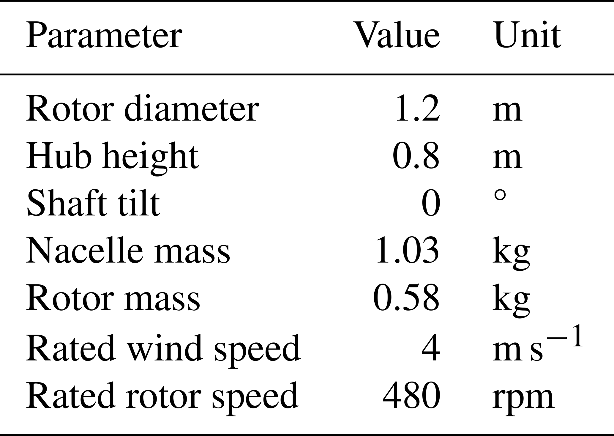
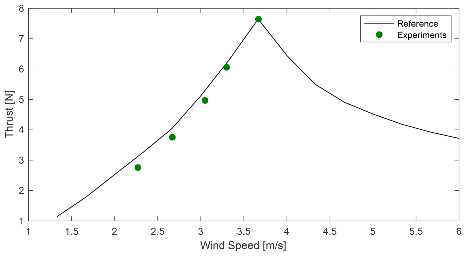
Figure 2Rotor thrust from experiments (Taruffi et al., 2024b) compared with the nominal thrust curve of the full-scale turbine (reported at model scale). The experimental points are averaged over two sets.
2.2 Hexapod
The motion system is the commercially available parallel kinematic robot Quanser Hexapod. The maximum velocity and acceleration are 0.67 m s−1 and 9 m s−2 for translations and 80 ° s−1 and 800 ° s−2 for rotations. The capabilities and limitations of the hexapod were evaluated with tests in the previous study (Taruffi et al., 2024b). A key outcome for this application is that the hexapod is capable of moving the wind turbine model at frequencies up to 5 Hz (0.1 Hz at full scale or 1.5 in terms of reduced frequency) with reasonable accuracy. The frequency range and acceleration limits are within the scaled motion range of 10 MW FOWTs for most load conditions with an operational sea state. The window of interest is towards low- and wave frequency ranges, while a response to tower and blade modes is out of the scope of this setup, considering that they are modelled as rigid.
2.3 Instrumentation
The instrumentation system consists of several sensors and a real-time controller. A six-component load cell (model ATI mini45 SI-290-10) installed between the tower top and the nacelle is used to measure the rotor integral loads and obtain the aerodynamic forces. Two MEMS triaxial low-frequency accelerometers (model TE Connectivity 4030-002-120), one placed at the hexapod–tower connection and the other one positioned on top of the nacelle, measure the translational accelerations. Both are used to verify motion tracking, and the one on the nacelle is also used, together with the load cell, for the aerodynamic force estimation process, as explained in Sect. 3.1.
The rotor is driven by a motor (model Maxon EC-4pole 30 200W) featuring a gearbox (model Maxon GP 32 C 5.8:1) and is connected to the rotor shaft with an Oldham coupler. The motor is controlled at a constant speed by a servo drive (model Maxon Escon 70/10) and is equipped with a braking resistor (model Maxon DSR 70/30) to dissipate the power generated. The servo drive provides the wind turbine operating data of rotational speed, measured by an encoder (model HEDL 5540) at the motor, and torque, calculated from the motor current.
A real-time machine (model dSPACE 1302) is used to run the hardware-in-the-loop controller, chaining measurements and actuation by simulating, in real time, the floater dynamics (see Sect. 3). The unit is also used for data acquisition of all the sensor signals and as a human–machine interface to set test cases, command the operation of the turbine model, and monitor the signals. The real-time machine operates at 1 kHz.
The wind speed is measured using a pitot tube installed in the tunnel nozzle. The speed at the testing location is also verified with a portable fan-type anemometer.
2.4 Scaling of FOWT concept
This hybrid setup is designed to be scalable and represent different FOWT systems in the size range of 10 MW with a scale around 1:150. The rotor is a scale model designed for the DTU 10 MW reference wind turbine, but it can represent other rotor ratings by adjusting the operating parameters according to the scale. Since the floater is represented by a numerical model, it is virtually possible to use any platform and mooring design.
As introduced in Sect. 1, one of the key drivers of hybrid testing is to be able to reduce the Froude–Reynolds scale conflict. For hybrid testing in wind tunnels, this translates into a custom scaling law (in Table 3) that comes as close as feasible to the Reynolds scale bearing in mind the limitations given by the facility, the model manufacturing, and the actuation system. The Reynolds mismatch is reduced if compared to fully physical testing in a wave basin; however, a performance scale approach for the rotor is still needed.
A non-Froude scaling introduces an acceleration mismatch, which results in an incorrect reproduction of the balance between inertial and gravitational phenomena acting on the wind turbine, while those acting on the floater are not affected as they are numerically reproduced. Moreover, a mass mismatch is hardly avoidable at these scales due to production constraints, resulting in a manufacturable RNA mass around 10 times the scaled value. The combination of these scaling issues leads to large errors and has to be numerically compensated for by the hardware-in-the-loop setup for a correct reproduction of the full-scale dynamics, as explained in Sect. 3.1.
A limitation on the size of the reproducible FOWT is given by the scaling. Representing bigger concepts with the same setup, as a 15 MW FOWT or more, increases the scaling effects. On the aerodynamic side, an increase in the Reynolds number mismatch with the scale worsens the performance of the rotor. On the actuation side, the motion needs to be quicker, approaching the limits of the hexapod in terms of motion frequency whose scaling is governed by and also challenging the hardware-in-the-loop chain latency.
Ultimately, an openly available 10 MW FOWT concept is chosen in this work with the scope of verification of the setup itself. This is the DTU 10 MW with the SWE TripleSpar floater (Lemmer et al., 2016), whose design was validated in Bredmose et al. (2017). The relevant properties of the concept are in Table 2. The load cases used as reference for the wave tests (in Table 5) are extracted from Ramachandran et al. (2017) and refer to a site located in the Gulf of Maine.
Table 2Properties of the FOWT concept from Bak et al. (2013) and Lemmer et al. (2016).
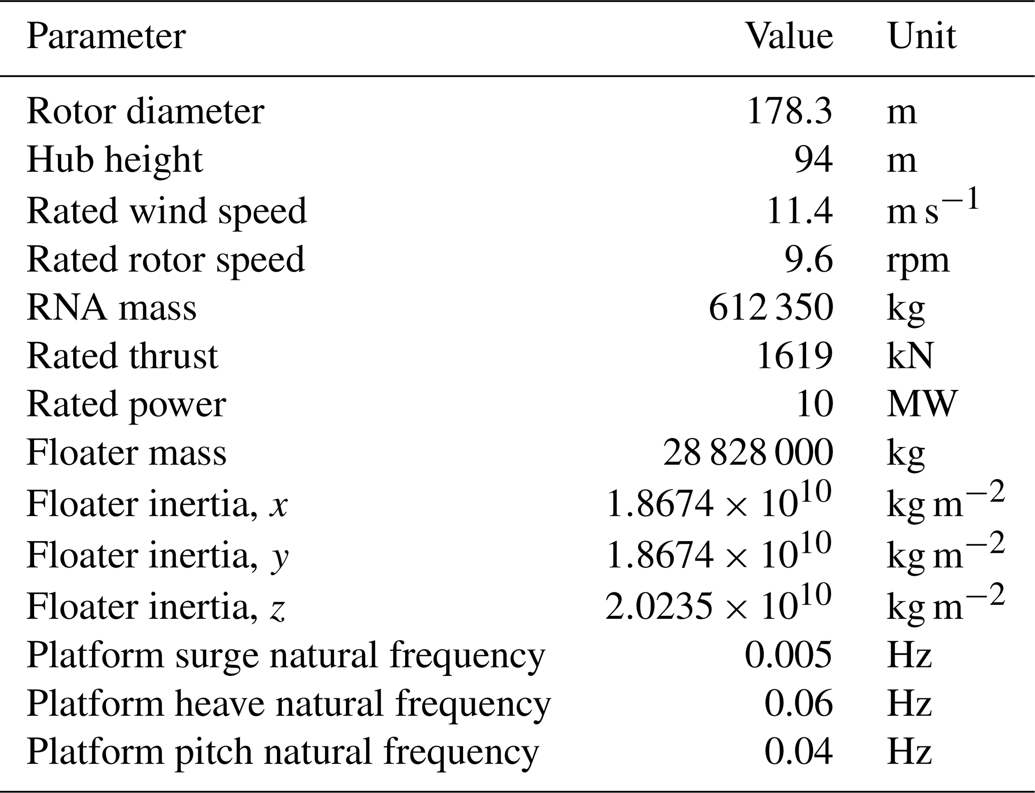
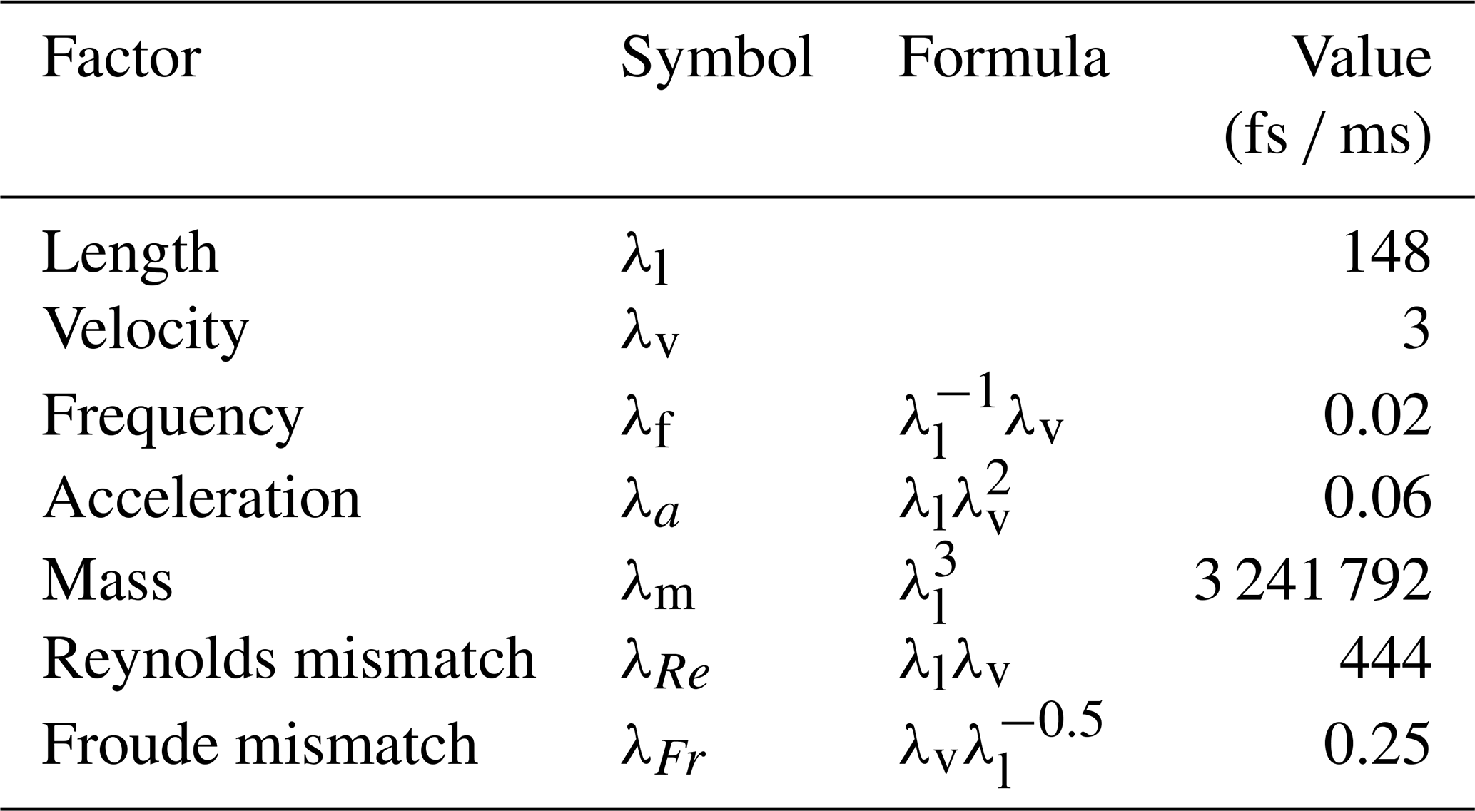
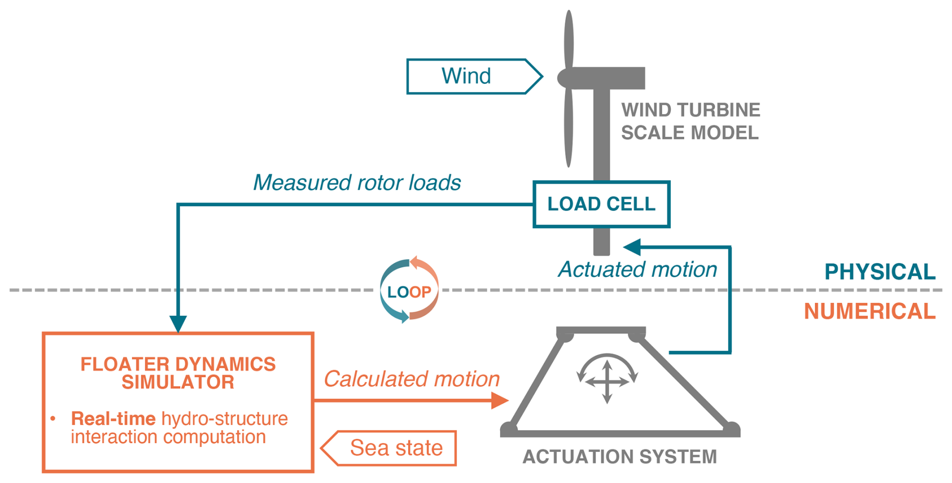
Figure 3Scheme of the HIL architecture showing the force-feedback and motion-actuation chain.
This setup's HIL architecture is of the force-feedback–motion-actuation type. The aerodynamic loads are measured on the physical model and are fed into the floater simulator, which calculates the next state of the system and actuates the hexapod, which moves accordingly. The floater simulator is an HIL numerical model developed in a MATLAB/Simulink environment to run in the real-time machine, and it solves the dynamics of the floater in real time by integrating the equation of motion at each time step, accounting for the measured aerodynamic loads, the numerically generated sea state and the hydrostatics, hydrodynamics, and mooring system of the floater (see Sect. 3.2). The motions affect the measured aerodynamic loads, which in return affect the calculated motions at the next time step. This creates a loop and allows for the two-way coupling of the rotor aerodynamics with the floater dynamic motions. A scheme of the HIL architecture is shown in Fig. 3.
3.1 Force correction
Measuring pure aerodynamic loads with a load cell is not feasible for dynamic applications such as the one of interest here. The load cell measures at least the entire rotor load and, depending on where it is positioned, also the nacelle and tower loads. This includes aerodynamic, inertial, and gravitational contributions. Similarly to Fontanella et al. (2023b), here the load cell used for the force feedback is positioned between the tower top and the nacelle, instead of under the tower as in Belloli et al. (2020), and thus measures the loads acting on the RNA only. The advantage of measuring at the top of the tower is that the fraction of aerodynamic forces over measured forces is greater as the tower's inertial contributions, which are large given its non-scaled mass (the tower is designed as rigid), are not measured.
However, the measured rotor-nacelle forces cannot be directly used in the floater simulation, and a correction procedure is necessary for two reasons. Firstly, the non-Froude scaling chosen for the setup (see Sect. 2.4) implies that the acceleration factor is not 1; thus the accelerations must be scaled. This also applies to the gravitational acceleration, which is not feasible to scale in experiments, leading to a gravitational acceleration mismatch between the physical and numerical parts of the experiment. Secondly, the mass of the rotor and nacelle cannot be scaled correctly due to manufacturing constraints that make it unfeasible for models in this scale range (1:100–1:200). This is due to the complexity of the RNA with the need for sensors, actuators, and mechanical components and the necessity of preserving the structural integrity of the scaled model, which poses critical requirements for the blade manufacturing. These acceleration and mass mismatches result in the misrepresentation of gravitational and inertial forces in the experiments. Since these forces are measured by the load cell together with the aerodynamic forces, which are not affected by mis-scaling, it is not possible to use the measurements as they are as feedback. To give an order of magnitude of the impairment, the acceleration mismatch of 15 and the mass mismatch of 10 lead to a mismatch in the ratio between the aerodynamic forces and the inertial and gravitational forces of 150. With aerodynamic forces and their effects being the focus of study in this setup, it is clear how this significant error would impair the experiments.
For this reason, a correction procedure is needed in real time during the experiments. It is developed in this work, as described hereafter, and is performed by the HIL model. The measured loads are cleansed from the incorrect inertial and gravitational components, and the estimated pure aerodynamic forces and torques are fed into the dynamic simulator, which numerically accounts for the true inertial and gravitational effects on the turbine together with the floater ones. In this work, it is not possible to apply a force correction a posteriori, as in Taruffi et al. (2024b), where the forces were corrected as a post-processing step because of the uncoupled nature of the prescribed motions. Here, the dynamics are fully coupled, and the measured loads are utilised in real time to solve the floating motion, and therefore, the correction has to be done in real time. The aerodynamic forces and torques are estimated as
where Faero and Taero are the estimated aerodynamic forces and torques, Fmeas and Tmeas are the forces and torques measured by the load cell placed under the nacelle, Fcorr and Tcorr are the correction forces and torques, Fin and Tin are the inertia forces and torques, and Fgrav and Tgrav are the gravitational forces and torques. The forces and torques have three components each (x, y, and z, where x is in the direction of surge, or along-wind; y is in the direction of sway, or lateral; and z is in the heave direction, or vertical). Thus, to obtain the aerodynamic forces, the inertial and gravitational forces that the load cell is measuring have to be estimated. This is done as follows:
where Mrna is the mass of the scale model RNA; Jrna is the moment of inertia; ameas is the translational acceleration measured by the triaxial accelerometer placed at the nacelle; R is the rotation matrix (see Sect. A2); and zlc is the vertical distance between the centre of mass and the load cell sensor (zlc=0.035 m), expressed in the rotating frame linked to the load cell. The value of Mrna is estimated at 1.6 kg via system identification by actuating known motions and reading inertia forces with the same load cell as in the tests.
Using accelerations derived from the hexapod position feedback was found to be unsuitable, as it introduces errors due to the differentiation and operation and the time delays between the load cell sensor signals and the hexapod feedback. Instead, the signals measured by the accelerometer placed at the nacelle are utilised. The advantage lies in the usage of direct measurements taken at the location where the forces are also measured, therefore reducing latencies between the two and transformation errors. A limitation of this implementation is the neglect of the inertia torque terms , , and because of the lack of a reliable source for , , and given that no rotational acceleration is measured. The force correction analysis (see Sect. 3.3.2) proves that this does not affect the roll and pitch directions, where the translational acceleration term Mameas is dominant. There is essentially no correction in the yaw direction, but this does not seem to affect the response. After the correction, the estimated aerodynamic forces are transformed from the rotating reference frame centred at the nacelle to the non-rotating reference frame centred at the FOWT still-water level, corresponding to the tower base of the model, used as origin in the floater dynamic model.
3.2 Floater dynamics
A numerical model is developed to simulate the floater dynamics. This model takes as input the estimated aerodynamic forces and computes the motion response of the FOWT in 6 degrees of freedom, returning as output the position to be imposed on the hexapod. A compromise between fidelity and computational cost has to be made to ensure the capability of running the model in real time. Thus, the modelling follows a mid-fidelity approach, similar to the widely used simulation tool FAST (Jonkman and Buhl, 2005) and previous HIL setups (Belloli et al., 2020). The focus of this setup is on the motion-induced aerodynamic loads, and the floater dynamics have to be reproduced sufficiently accurately to produce realistic motions, by which the aerodynamics are affected. The focus of this study is not on analysing the details of hydrodynamics or mooring effects. For this reason, a higher-fidelity hydrodynamic model (e.g. computational fluid dynamics) is out of scope and not feasible given the real-time constraints.
The motion response – in physics-based models – is determined by solving the equations of motion. For FOWTs, this is commonly done with a derived version of the Cummins equation (Cummins, 1962), which models the complete dynamics of the floater as a damped spring–mass system subjected to external forces, such as aerodynamics, hydrodynamics, and mooring forces. The model used here is targeted at semi-submersible floaters, and the equations of motion are given by
where M is the structural mass, R is the linearised viscous damping, and K is the total stiffness. All are 6×6 matrices. The external 6×1 force vectors are Fhydro for the hydrodynamic force and Faero for the aerodynamic force. Additionally, x is the position coordinate vector, is the velocity vector, and is the acceleration vector. The stiffness terms include the gravitational (Kgrav), mooring (Kmoor), and hydrostatic contributions (Khst). A comprehensive equation of motion is detailed in Appendix A4.
The hydrostatic and hydrodynamics are modelled using the potential flow theory. The effects considered are hydrostatic restoring, radiation loads, and first-order incident wave diffraction. Their calculation relies on panel code (e.g. WAMIT) simulation outputs that represent the floater's hydro-properties. The hydrostatic restoring contribution is accounted for in the stiffness matrix of the system, while the infinite-frequency added mass is in the mass term. The first-order diffraction forces – the total first-order wave excitation including the Froude–Krylov and scattering components, as per the Newman interpretation – are pre-calculated based on the sea state corresponding to the test case and use the JONSWAP spectrum for irregular waves with the WAFO tool (Brodtkorb et al., 2000). The radiation forces instead need to be calculated in real time. Normally, a convolution integral needs to be computed to keep the memory effect; however, given the real-time application, a state-space approximation is preferred. The state-space model parameters are identified using a state-space identification tool developed by Duarte et al. (2013). A linear approach is used for the mooring lines in the form of a stiffness matrix.
The properties of the selected concept relevant to building the dynamic model are in Table 2 and are obtained from Lemmer et al. (2016) and Lemmer et al. (2020), where the hydro-properties are available. As detailed in Sect. 3.3.1, the model is then tuned with FAST (v8.16) as a benchmark.
3.3 HIL assessment
Prior to wind tunnel testing, the HIL setup is assessed in cases without wind to ensure the trustworthiness of the results in wind cases. Both the dynamic model and the HIL architecture itself, namely the measurement and actuation loop and the force correction method, are verified. This is done following a methodology that can be considered best practice for hardware-in-the-loop wind tunnel testing and covers three steps of assessment and measurements:
-
tuning and verification of the dynamic model;
-
verification of the measurements, correction, and actuation loop; and
-
aerodynamic measurements.
3.3.1 Floater simulator
Step 1 is to verify the dynamic model simulating the floater. This is done by performing standalone simulations in Simulink, and it corresponds to testing in open loop, i.e. without force feedback. This step assesses the modelling of the FOWT rigid-body dynamics, hydrodynamics, and mooring. FAST is used as a benchmark for comparison. In this step only, the simulations are performed at full scale on a non-real-time machine, and the robot is not connected. Therefore, only the result of the simulation is considered, not the motion of the hexapod.
The rigid-body dynamics are determined with free decay simulations individually for each degree of freedom. Free decays are commonly used to characterise the rigid-body dynamics of floating systems, from which the natural frequency and linear damping ratio are evaluated. The simulations, in both Simulink and FAST, are run with no wind and no rotation of the rotor. The mooring is simulated dynamically in FAST using the MoorDyn module and linearly in Simulink.
The dynamic model is fine-tuned, adjusting the damping and stiffness term to match the FAST simulations. This tuning process is done iteratively and for each degree of freedom. Damping requires adjustments because the HydroDyn modelling of the FAST module is more complex, while stiffness requires it as a linear mooring model is tuned with a nonlinear model. Small initial conditions (2 m for translational DOFs and 2° for rotational DOFs) are used to stay within a fairly linear range in the mooring reproduction in the benchmark.
The comparison between the decays for each DOF can be seen in the time domain in Fig. 4, where the tuned dynamic model closely resembles the response of FAST, and the obtained values of the natural frequency and damping ratio, the latter using the logarithmic decrement, are reported in Table 4. Overall, the decay responses match satisfactorily.
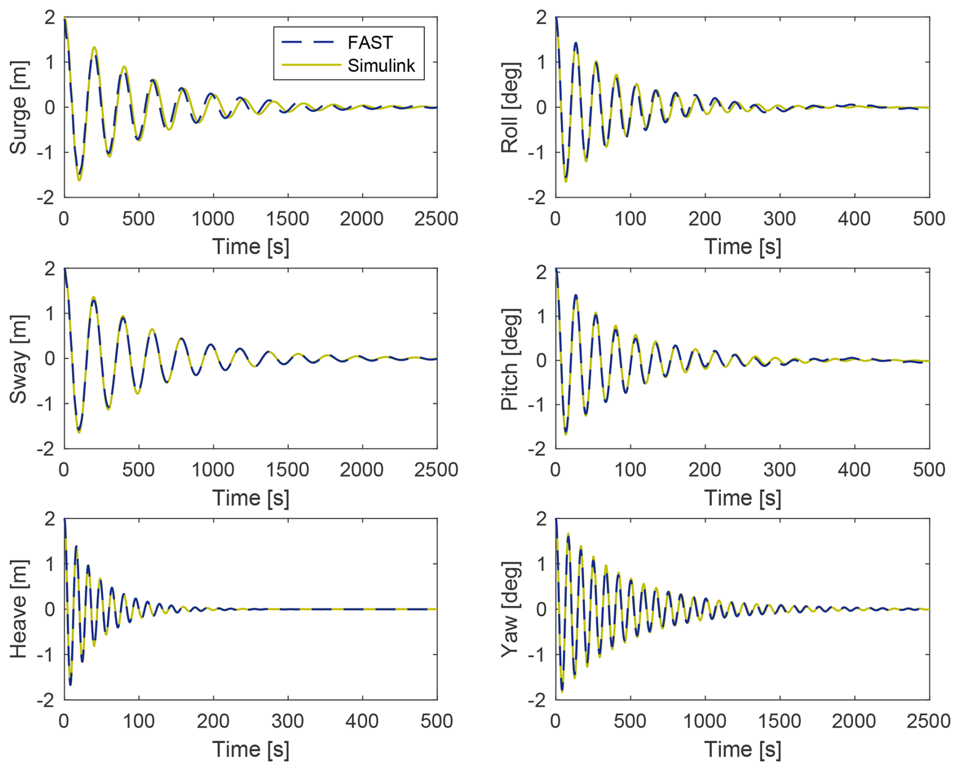
Figure 4Time histories of floater DOFs for decay simulations with FAST (benchmark) and with the standalone HIL numerical model.
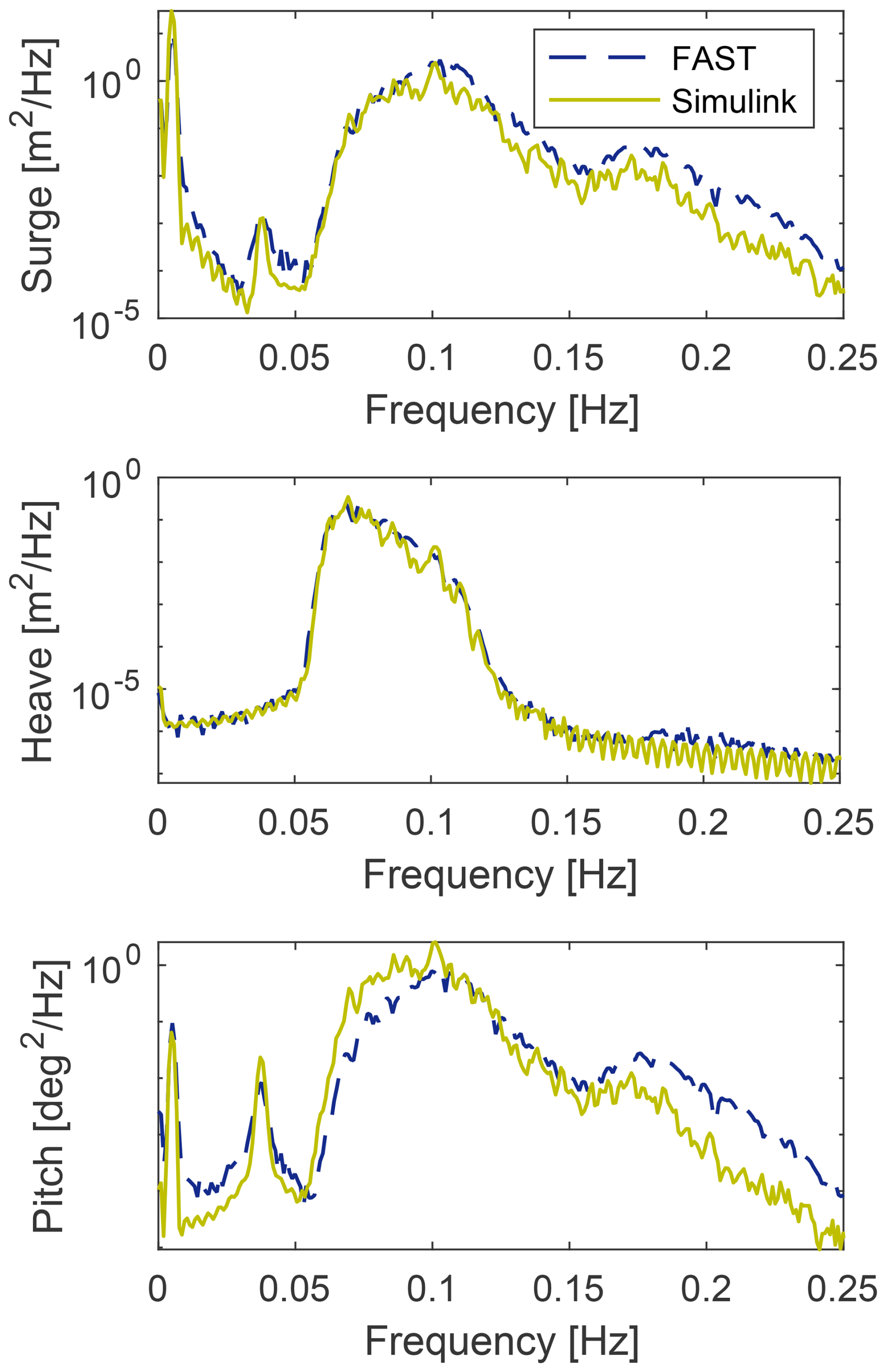
Figure 5PSD of floater motion response to wave loading of simulations with FAST (benchmark) and with the standalone HIL numerical model.
The wave response is evaluated with simulations in wave conditions, using case 4 from Table 5. The comparison is performed in the frequency domain given the different random seeds used for wave generation. The motion PSD for the DOFs affected by wave forces, namely surge, heave, and pitch, in Fig. 5 shows a satisfactory match.
3.3.2 HIL setup
With the verified dynamic model, step 2 is to assess the HIL architecture itself, and specifically the force-feedback and motion-actuation chain, with the force correction procedure. To do so, it is necessary to isolate its effect. This is done by testing in closed loop (with the force feedback activated) and comparing the same case tested in open loop (simulation without force input). Free decay cases in each DOF are performed in no-wind and no-rotation conditions so that the only difference with the open-loop tests is the activation of the force feedback. Since there is virtually no aerodynamic force involved, considering that the aerodynamic force developed by the non-rotating rotor is small, ideally the motion response in closed loop should exactly match that in open loop. This implies that the loop and the force correction work correctly, and all the rotor non-aerodynamic loads, which are undesired inertia and gravitational forces measured by the load cell in the closed-loop configuration only, are cancelled out correctly. An incomplete or wrong correction would result in a different motion response, for example, an amplification or a change in natural frequency and damping.
The comparison is shown in the time domain in Fig. 6, and Table 4 reports natural frequency and damping values. The open-loop and closed-loop tests match closely. Even the response in yaw shows discrepancies only after a few cycles, despite the total lack of force correction in this DOF, as explained in Sect. 3.1. The error of neglecting the correction is still present and could become significant for other load cases; however, this study tests cases with aligned wind and waves, where the yaw response is expected to be small, and, for this reason, the error has a limited impact. The response of the other rotational DOFs, roll and pitch, does not seem to be affected by the incomplete correction they are subject to. The pitch decay with the closed loop appears more damped in the first cycles, but this effect can be attributed to the drag of the non-spinning rotor being non-null and dampening the pitch motion in the first cycles where the hub velocity is high, given the big initial condition tested. This is the only difference between pitch and roll – which match well – that could explain the discrepancy.
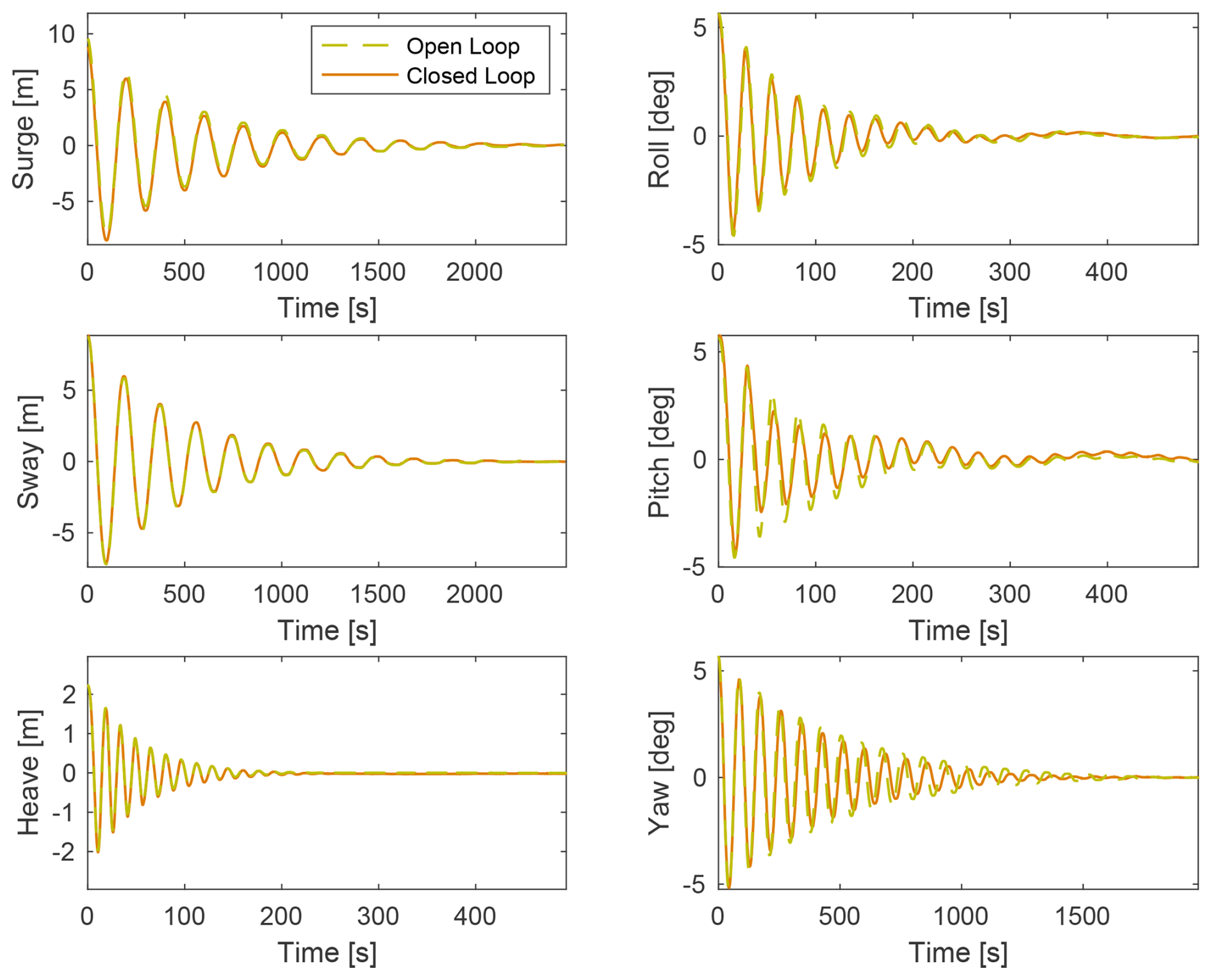
Figure 6Time histories of floater DOFs for decay tests with the HIL setup in open-loop and closed-loop configurations. The results are upscaled.
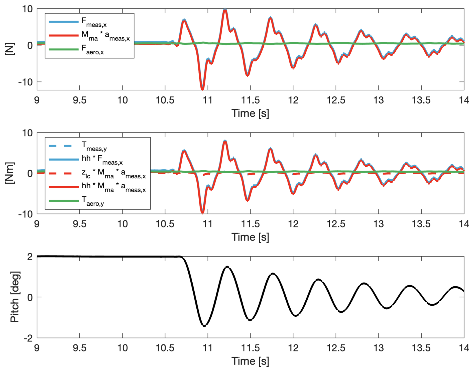
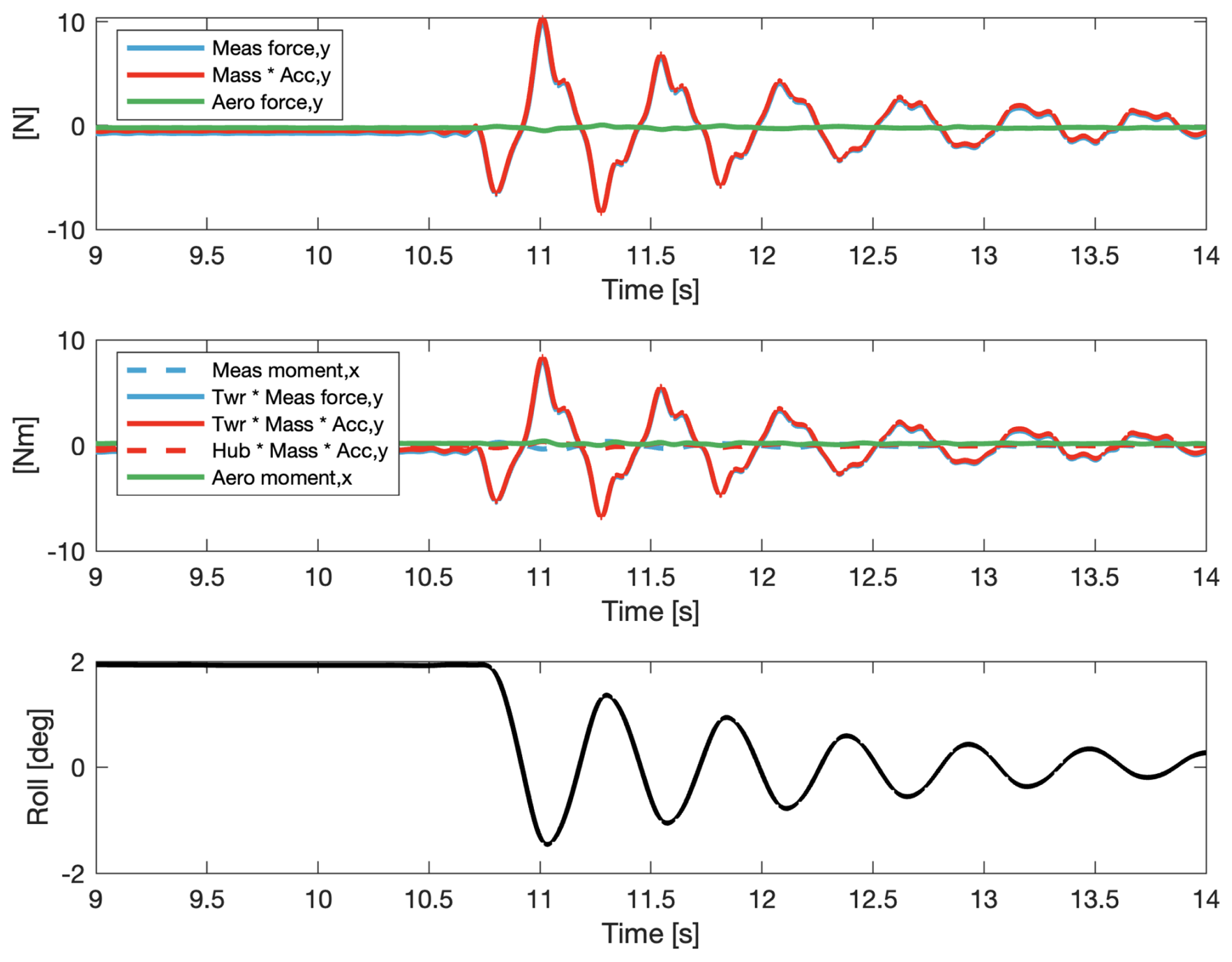
An analysis of the force correction breaks down how the methodology is applied by the HIL with actual signals. It shows the correction of along-wind force Fx and torque Ty for a pitch decay without wind. This is the most relevant case because Fx and Ty are in the direction of wind and thus of thrust; pitch shows faster oscillations than surge and is therefore more critical; and the no-wind case allows for an easier understanding of the performance of the correction, given that a good correction is achieved when the estimated aerodynamic force is zero. In Fig. 7, the bottom plot shows the pitch decay time history. The top plot shows the estimation of the aerodynamic force in the along-wind direction: the solid blue line is the measured rotor force Fmeas,x, the solid red line is the correction, and the green line is the aerodynamic force Faero,x estimated by the model. As desired, the estimated aerodynamic force is approximately null. The middle plot shows the estimation of aerodynamic torque in the along-wind direction about the tower base: the dashed blue line is the measured rotor torque Tmeas,y, the dashed red line is the signal used to correct it, the solid blue line is the measured rotor force Fmeas,x multiplied by the hub height (to calculate the torque at the tower base), the solid red line is the signal used to correct it, and the green line is the aerodynamic torque Taero,y estimated by the model. Despite, in theory, the fact that the dashed blue contribution is not entirely corrected by the dashed red contribution due to the neglect of the rotational acceleration term, the two are almost indistinguishable. Moreover, it is visible that the impact of the force arm is predominant when the moments are transported about the tower base, making the correction of Fmeas,x more important than the correction of Tmeas,y. Overall, the estimated torque is also approximately null, and this proves the negligible effect the incomplete correction has. The visualisation of the correction of other force components and of cases with wind is reported in Sect. A6.
Altogether, this assesses the HIL system, mainly the force correction procedure, and can give an indication of the expected accuracy of the results obtained in the wind tests.
3.3.3 Real-time limitations
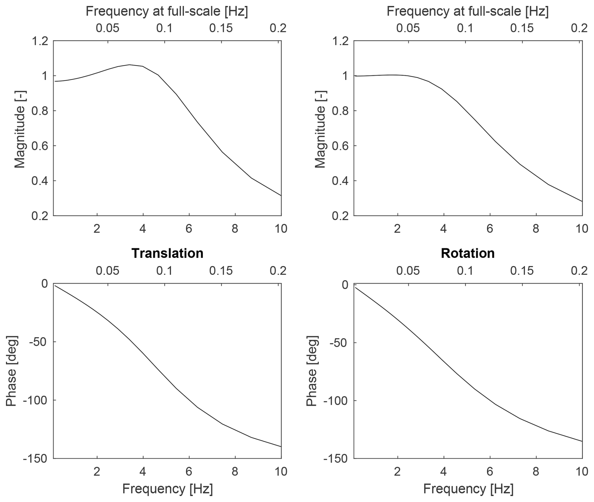
Keeping the real time in the floater simulation and ensuring that delays do not compromise the stability of the system are of fundamental importance. The real-time machine integrates the HIL model with a time step of 1 ms, and no delay compensation is implemented. No filter is applied to the force and acceleration inputs because all the filter and cut-off frequencies tested resulted in an unstable HIL system. The force and acceleration sensors show no visible lag between their signals, as shown in Fig. 7. This improves the force correction process because of the approach of using measured rather than derived signals for it. The sensors are used within their response range, i.e. 0–200 Hz for the accelerometer and higher for the force sensor, whose bandwidth is given by the resonant frequency, which is around 5000 Hz, from which a usable range of approximately 0–1000 Hz is assumed. The actuation latency of the hexapod is estimated considering the delay between the position command from the real-time machine to the hexapod and the position feedback from the hexapod to the real-time machine, and the latency between the command and actual motion is assumed to be half of this delay. The total latency between the physical phenomena, i.e. the aerodynamic loads acting on the rotor, and the motion that it induces is estimated to be less than 100 ms. To evaluate the motion tracking of the hexapod, the transfer function between the position set point and actual position is also estimated, and it is reported in Sect. A5. For the sake of being conservative, the estimated delay includes the phase shift of the actuation at the upper-frequency limit of 5 Hz.
After assessment of the HIL setup, aerodynamic measurements can be performed with wind tunnel tests as step 3. This work focuses on the HIL setup development and assessment; thus a limited number of tests and analyses are carried out. The aim is to explore the potential of the HIL setup for investigating the aerodynamic response of FOWTs. Decay tests are run to experimentally estimate the aerodynamic damping of the rotor, and a set of realistic combined wind and wave cases are tested to study the wind and turbine effects on the floater motion response. The aerodynamic tests are performed in wind conditions and with the turbine rotor spinning at a fixed speed. The HIL feedback system is always active (closed loop).
4.1 Aerodynamic damping
With HIL, the floater motion is not pre-calculated but computed in real time based on the measured aerodynamic loads. Thus, it is straightforward to quantify the effect of the rotor aerodynamic damping on the floater motion response and estimate the aerodynamic damping itself. This is achieved by performing closed-loop decay tests in wind conditions for each DOF and comparing the results with no-wind decays. From the comparison, the effect of the rotor aerodynamics can be investigated, and the aerodynamic damping can be quantitatively estimated. These cases are performed with the turbine operating in rated conditions (wind speed of 4 m s−1 and rotor speed of 480 rpm).
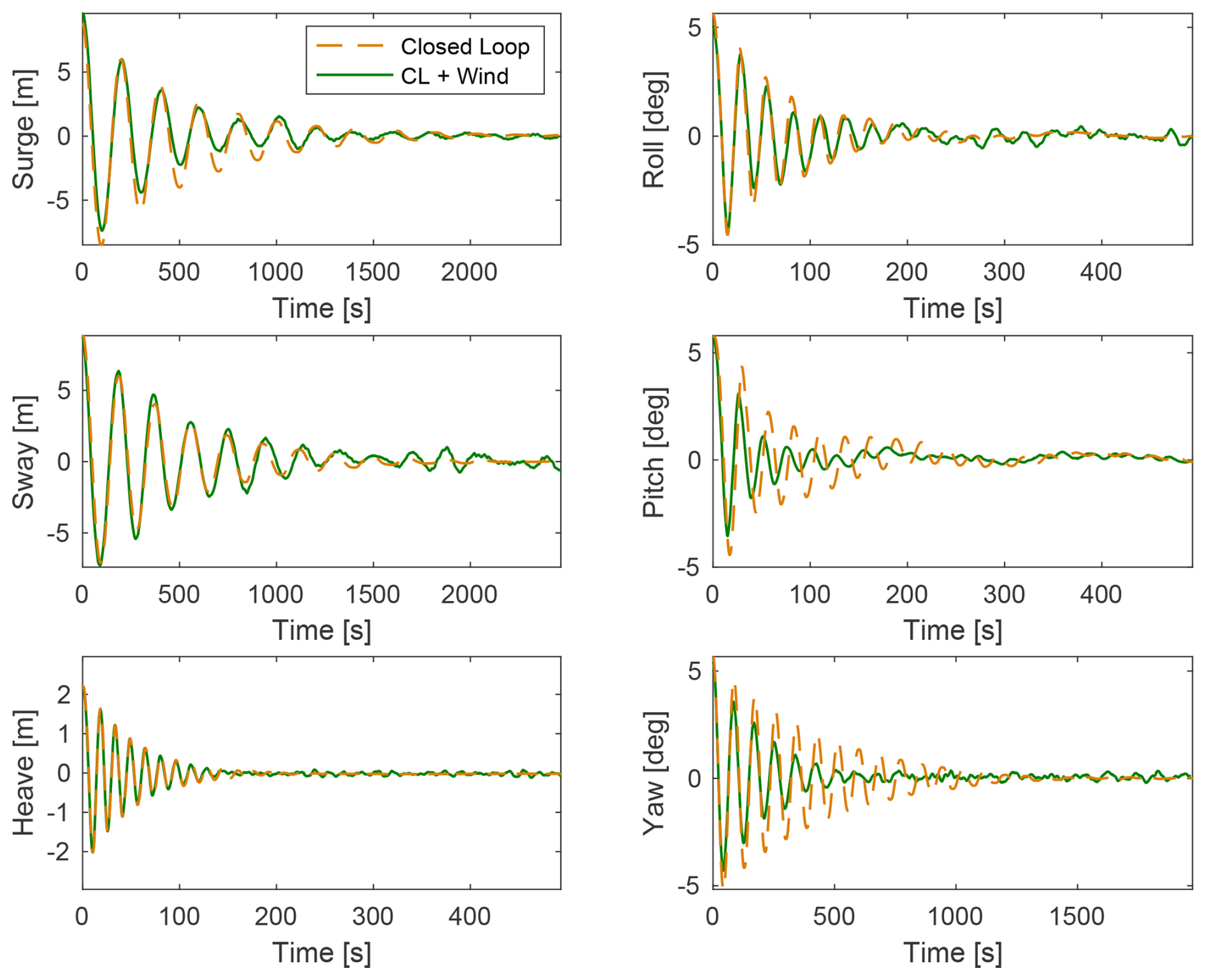
Figure 8Time histories of floater DOFs for HIL (closed-loop) decay tests in no-wind and wind conditions. The results are upscaled.
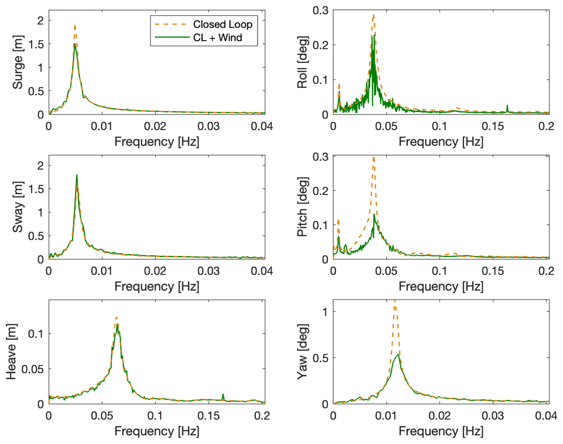
Figure 9Frequency spectra of floater DOFs for HIL (closed-loop) decay tests in no-wind and wind conditions. The results are upscaled.
The time domain comparison is shown in Fig. 8, and a frequency domain analysis is in Fig. 9. From the latter, the natural frequency of each DOF is visible as the highest peak. Before the peak of the natural frequency, there is another peak visible in roll and pitch. This smaller peak is the natural frequency of sway and surge, respectively. This peak is visible due to the coupling between roll and sway and pitch and surge. The smaller peak around 8 Hz in heave and roll is the 1P frequency of the rotor, visible only in these DOFs. The noise visible in the roll spectrum is attributed to the motor, which operates in that direction.
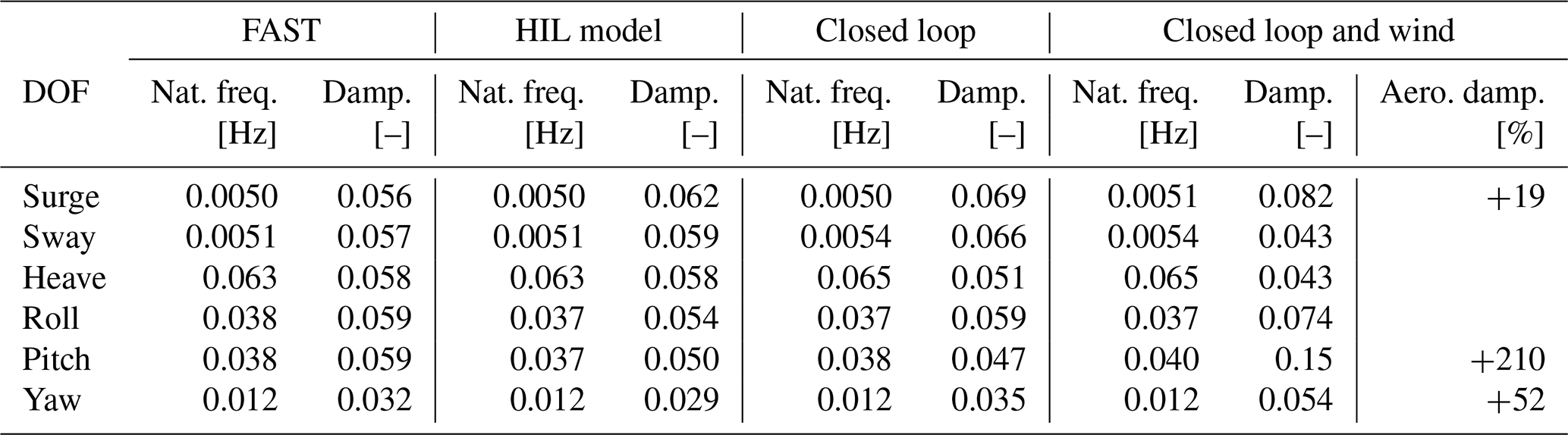
The spectra with wind show peaks that are lower and broader for surge, pitch, and yaw degrees of freedom. This implies that the rotor provides damping, as qualitatively explained hereafter. Assuming rotor speed and blade pitch are fixed as in the tests, the rotor moving against the wind direction in surge or pitch motions results in an increase in thrust force due to the increase in relative wind speed seen by the rotor. When the rotor moves in the direction of the wind, the thrust force decreases for the same reason. The increase and decrease in thrust force oppose the motion, slowing down the oscillation with a damping effect. A similar phenomenon explains the damping in yaw oscillation, where the part of the rotor that moves against the wind during the yaw rotation sees an increase in relative speed and consequently an increase in force in the wind direction which opposes the rotation. On the other side of the rotor, the opposite happens (a decrease in relative wind speed and a consequent decrease in force, which again opposes the rotation), ultimately causing the damping effect. A quantitative analysis is done to estimate the aerodynamic damping effect on DOF natural frequencies and damping, repeating the decay tests for three initial conditions, calculating the damping ratio with the logarithmic decrement, and averaging the results, which are reported in Table 4. The pitch DOF is the most largely affected, showing an average increase in damping of 210 % in rated wind compared to no wind. This is followed by yaw with a 52 % increase and surge with 19 %.
Table 4Natural frequencies and damping ratios of the floater DOFs obtained from decay cases with FAST, with the HIL model and in the HIL tests in closed-loop and closed-Loop and wind configurations. The values of closed loop and closed loop and wind are averaged over three different initial conditions and are upscaled to full scale for the comparison. The last column shows the effect of aerodynamic damping in wind-aligned DOFs.
4.2 Wind and wave tests
Combined wind and wave cases are tested to demonstrate that the setup is suitable for reproducing realistic loading conditions. Five irregular wave sea states are tested in total, each with a corresponding wind condition. The selected cases (in Table 5) are in the normal operational range of the FOWT as representative of a deployment site with a moderate sea state. They are selected to comply with the capability of the setup, as harsher waves cannot be tested because the motion response would go beyond what the hexapod allows in terms of accelerations. Also, the wind speed is capped to the rated value since the wind turbine model cannot operate at above-rated conditions due to the absence of blade-pitch actuation.
Table 5Load cases for combined wind and wave conditions. The operational irregular waves are from Krieger et al. (2015), and the corresponding uniform wind speed is capped to rated. All parameters are at full scale.
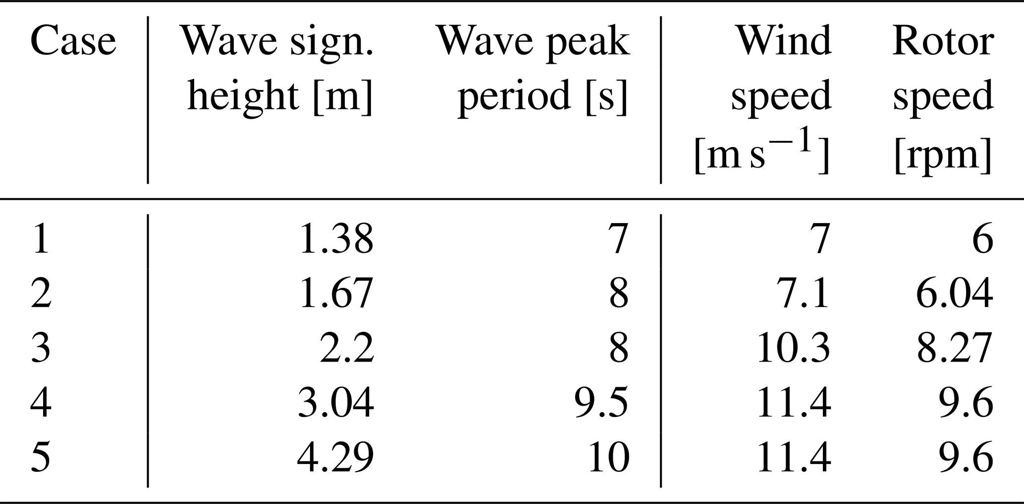
From the motion response PSD in Fig. 10 for an operational wind and wave case with wind speed at the rated value (case 4), it is visible that there are two significant areas of activity. The first is near the natural frequency range of the floating platform, which is towards the lower frequency range; this is also the region where the effects of wind are visible (Larsen and Hanson, 2007). This region is also known to be subjected to effects due to the HIL itself (Fontanella et al., 2023b), which are not investigated in this work. The second is near the wave frequency range, where the activity due to the emulated wave can be observed. The frequency of the highest-energy wave is denoted with a dashed line. The responses in the surge, pitch, and heave DOFs are more pronounced in this region; this is expected since the wave heading in these test cases is set at 0°. Finally, the rotor 1P frequency, denoted with the dotted line, shows a significant response in the heave and the roll DOFs compared to other regions of activity, and response is present in this frequency in all DOFs. A comparison of the motion response for all the load cases is shown in Fig. 11. The motion response increases with rising sea state and wind conditions, and this occurs across the entire frequency range. Case 5 shows outlier behaviour, also deviating from the other cases in DOFs like sway and roll that should be less affected by wind and wave loading. This can be attributed to reaching the limit of the hexapod or the HIL system, or to increased vibrations, and gives an indication of the limited capabilities of the setup. The dynamic response to wind and waves is qualitatively in line with what is found in the literature of HIL studies, such as in Belloli et al. (2020), where similar areas of activity were found, confirming the suitability of the setup for this kind of study.
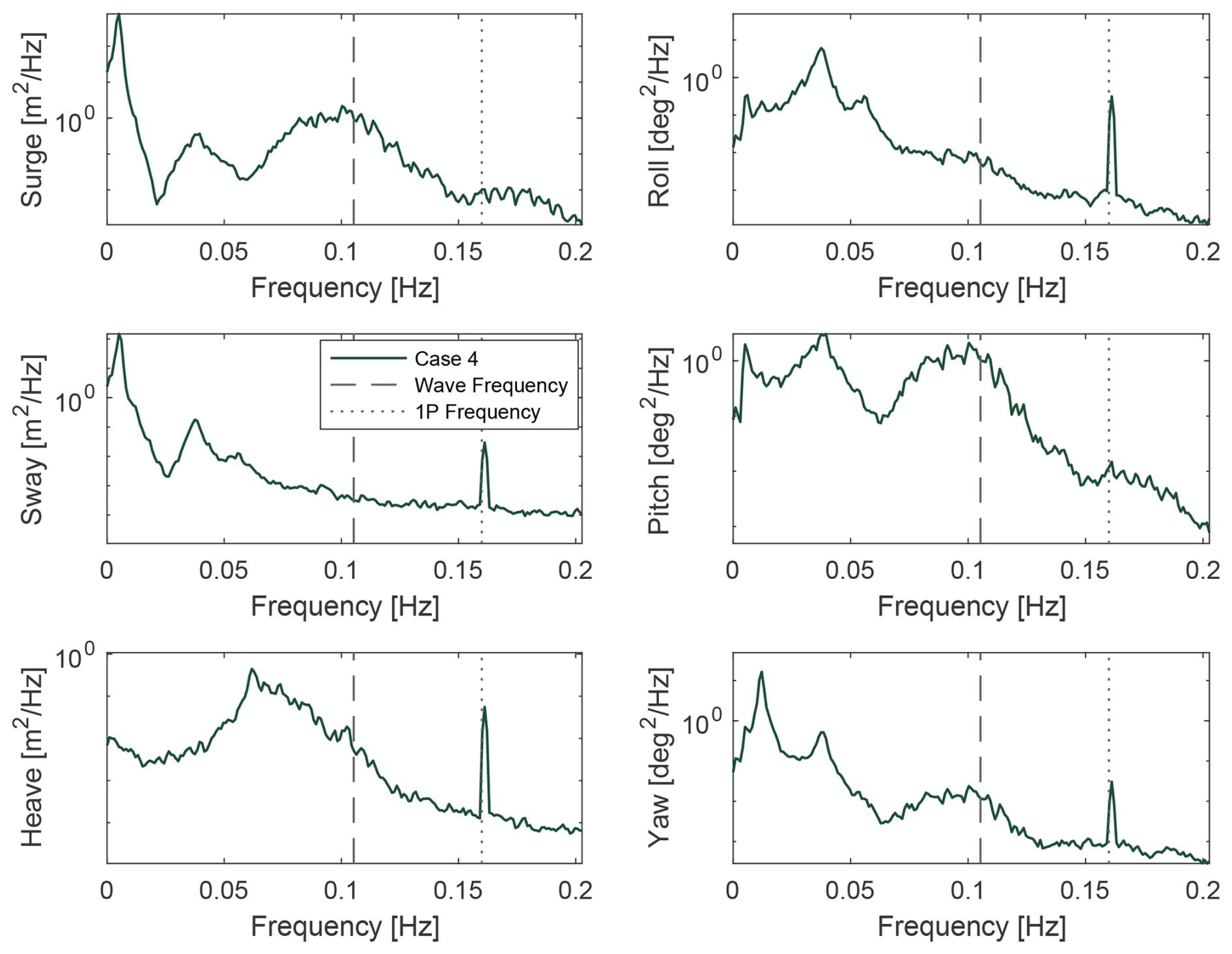
Figure 10PSD of floater motion response to the combined wind (HIL in closed-loop configuration) and wave loading for case 4. The results are upscaled.
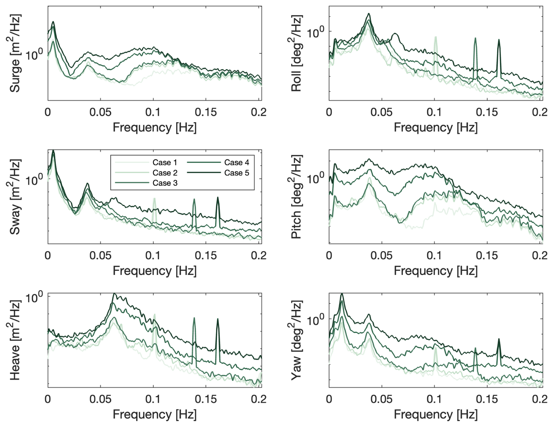
Figure 11PSD of floater motion response to the combined wind (HIL in closed-loop configuration) and wave loading for cases 1 to 5. The results are upscaled.
This work presents a hardware-in-the-loop wind tunnel setup designed to study the coupled aerodynamic and motion response of floating offshore wind turbines. By including the aerodynamic feedback in real time, the setup enables the study of phenomena such as aerodynamic damping and motion-induced rotor loading that cannot be captured in uncoupled experiments. At the time of writing, only two other wind tunnel HIL setups exist for this purpose, and few experiments have been carried out with the full dynamic coupling. There is thus a need to develop additional and complementary setups for comparison and advancing experimental investigations on floating turbines.
A key characteristic of the setup presented in this work is its ability to move in 6 degrees of freedom. This allows for the analysis of realistic motions, as encountered offshore, as well as investigating coupling effects between different DOFs. Another important achievement of this work is the development and implementation of a new aerodynamic force correction methodology, necessary to compensate for scaling inconsistencies in mass and acceleration between the physical and numerical subsystems. The method relies on measured accelerations at the nacelle instead of derived ones from the hexapod position feedback, minimising uncertainty and latency and significantly improving the accuracy of the estimated aerodynamic loads. The assessment of the correction procedure showed that the omission of rotational acceleration terms does not affect roll and pitch responses and that the induced error in yaw is minimal. The assessment of the HIL architecture confirmed that the correction and actuation chain performs consistently. The open- and closed-loop decay tests matched closely across all degrees of freedom, demonstrating that the setup correctly cancels non-aerodynamic loads in real time.
The setup allowed for a direct experimental estimation of aerodynamic damping. An increase in damping of pitch, surge, and yaw DOFs is expected, and this setup allows for quantifying it with measured rotor loads. The results shows a 210 % increase in pitch damping, a 52 % increase in yaw, and a 19 % increase in surge under rated operating conditions, highlighting the role of rotor aerodynamics in stabilising platform motions. Combined wind and wave tests demonstrated the capability of the setup to reproduce realistic offshore loading conditions. The motion responses in surge, heave, and pitch followed the expected behaviour across the wave frequency range, and the setup remained stable within the operational limits of the hexapod.
In conclusion, this work introduces an assessed experimental HIL framework for FOWT aerodynamic-oriented studies. It allows for analysing the unsteady aerodynamics of floating wind turbines, as well as comparing with the results of HIL in different facilities (e.g. HIL wind tunnels of different sizes, HIL wave tanks). Future studies will build on these results, extending the methodology to address remaining challenges, such as further improving the accuracy of force estimation and including delay compensation, and exploring the aerodynamic behaviour of new turbine designs under increasingly realistic conditions. The framework also sets the basis for validating high-fidelity numerical models.
A1 Force correction methodology
As an addition to Sect. 3.1, a more complete analytical formulation of the force correction methodology used in the HIL model is illustrated in this Appendix. This is to explain the theory behind the formulation in Eq. (1).
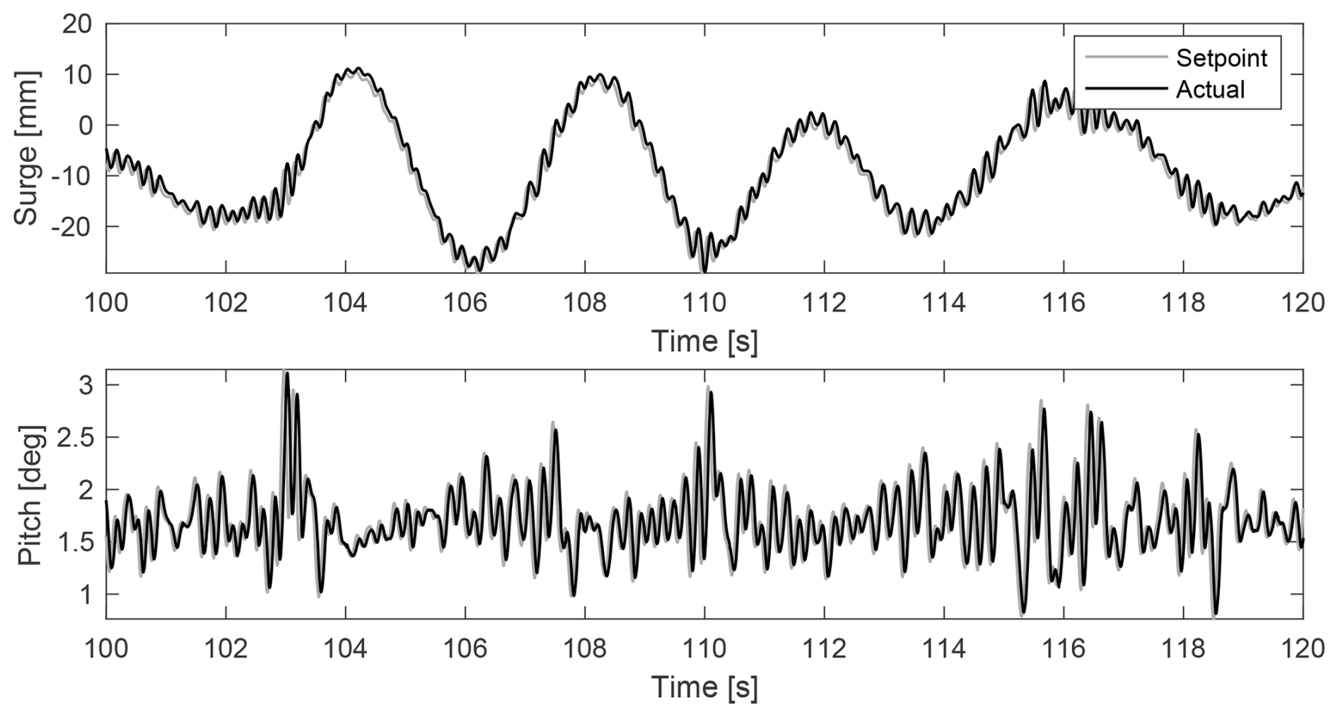
Figure A1Time history of surge and pitch set point and actual hexapod position for a wave case.
The forces and torques measured by the load cell, under the rigid-body assumption, installed under the nacelle can be analytically expressed as
and
where
-
Fmeas is the force measured by the load cell;
-
Tmeas is the torque measured by the load cell;
-
Faero,x, Faero,y, and Faero,z are the aerodynamic forces;
-
Taero,x, Taero,y, and Taero,z are the aerodynamic torques;
-
Mrna is the mass of the RNA;
-
Jrna is the inertia of the RNA;
-
g is the gravity acceleration;
-
R is the rotation matrix;
-
hh is the hub height;
-
zlc is the distance between the RNA centre of mass and the load cell;
-
, , and are the acceleration in surge, sway, and heave (in the fixed frame at the tower bottom);
-
, , and are the rotational accelerations in roll, pitch, and heave (in the fixed frame); and
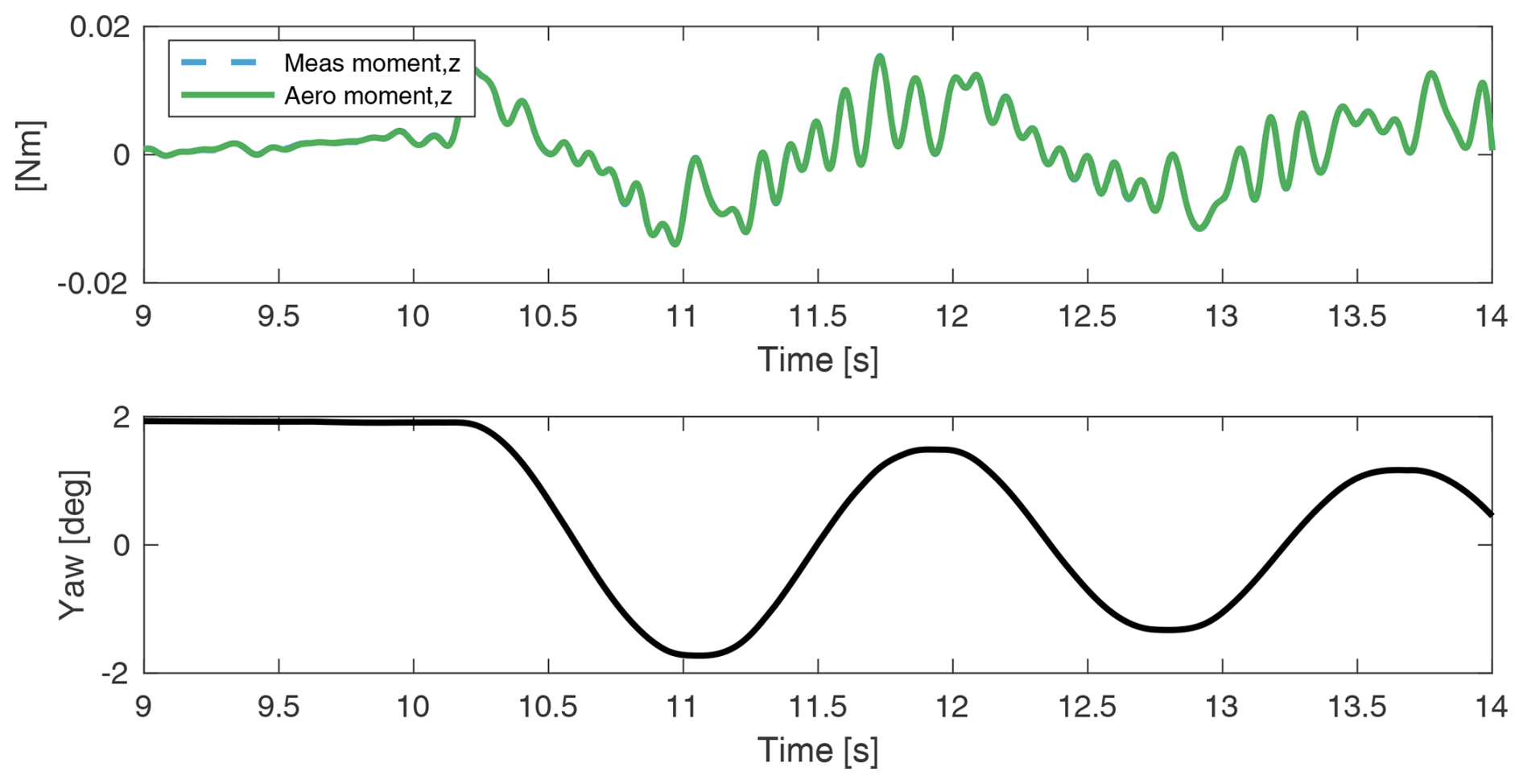
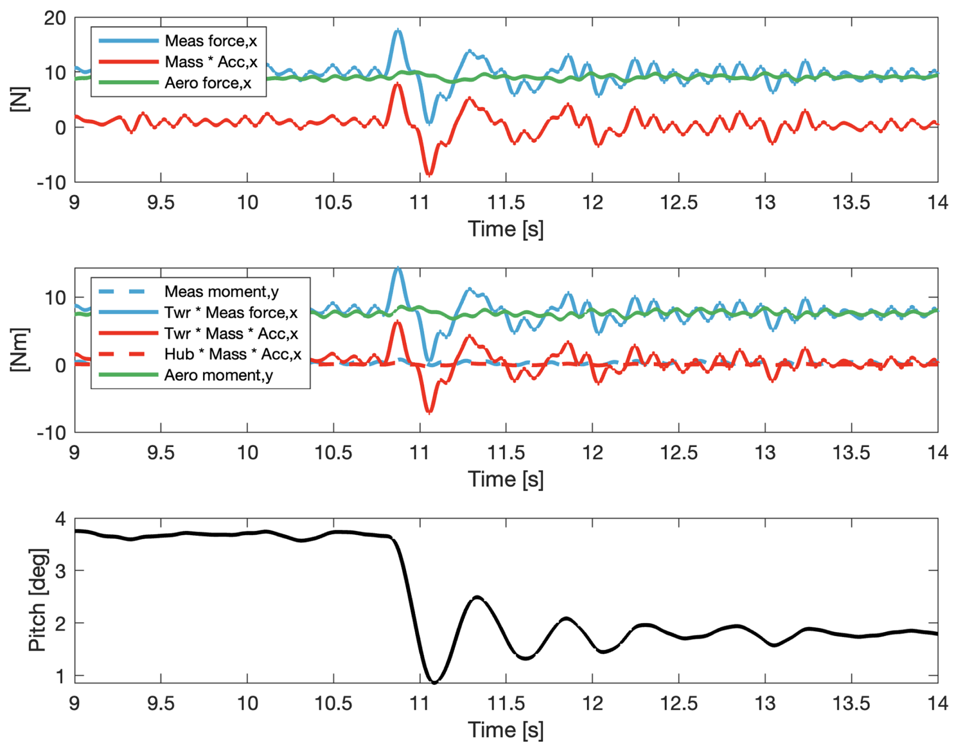
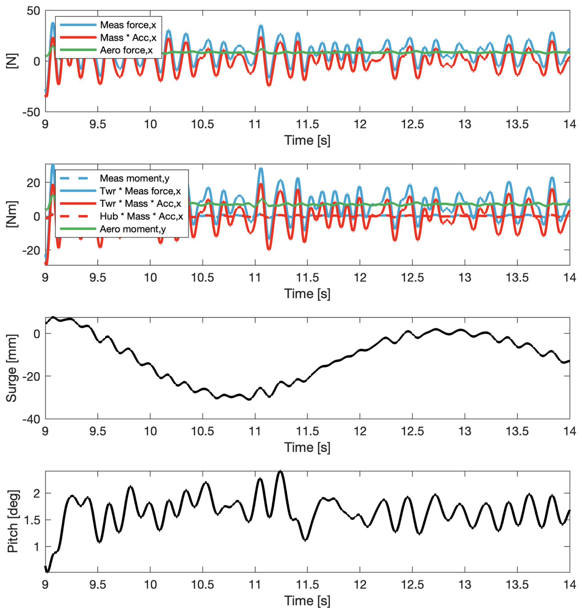
Figure A6Force correction in the along-wind direction for a pitch decay with rated wind and spinning rotor.
The accelerations measured by the accelerometer installed at the nacelle can be analytically expressed as
where
-
ameas is the acceleration measured by the accelerometer;
-
g is the gravity acceleration;
-
R is the rotation matrix;
-
hh is the hub height;
-
, , and are the acceleration in surge, sway, and heave (in the fixed frame at the tower bottom); and
-
, , and are the rotational accelerations in roll, pitch, and heave (in the fixed frame).
The formulation of the force correction in Eq. (1) is obtained from here. It has to be noted that the present formulation neglects gyroscopic effects and does not correct for them.
A2 Rotation matrices
Rotation transformation matrices are used in the HIL model. This is necessary because the equation of motion is solved in the fixed frame, while the acceleration and force measurements are taken by sensors attached to the wind turbine, which are in a moving frame. The rotation matrices are first determined to transform from the moving frame to the fixed frame. The rotation matrices are as follows.
Yaw rotation:
Pitch rotation:
Roll rotation:
The order of rotations, or the Euler sequence, plays a crucial role in the transformation matrix, as different sequences can yield different results. For a 6-DOF system, the transformation matrices are multiplied 3-fold, so the rotation order must be set correctly to avoid amplifying errors. The generally accepted order of rotation is the yaw–pitch–roll transformation. When applying this transformation, the matrices are multiplied in the roll–pitch–yaw order. The final rotation matrix is
This order of rotation is used to make a transformation from a rotated reference frame to a fixed reference frame. The inverse of the transformation is used to make a transformation from a fixed frame to a moving frame.
A3 Force rotation and transport
The forces have to be transformed from the rotating frame where they are measured into a fixed frame. The equation of motion is solved at the mean sea level (MSL), i.e. at the tower base. Hence, the transportation of the forces to the tower base is also necessary. The aerodynamic force and torque used in the equation of motion (, where tb stands for tower bottom) are
A4 Equation of motion
A complete formulation of the equation of motion of the rigid-body dynamics of FOWTs is shown here to complement Eq. (4):
where
-
Ms is the structural mass and inertia matrix of the whole FOWT (rotor included)
-
A is the infinite-frequency hydrodynamic added mass
-
Rvisc is the linear viscous hydrodynamic damping matrix
-
Kgrav is the gravitational restoring stiffness matrix of the entire FOWT (rotor included)
-
Khst is the hydrostatic restoring stiffness matrix
-
Kmoor is the linearised mooring stiffness matrix
-
Frad is the calculated radiation force (with state-space approximation)
-
Fdiff,1 is the generated first-order diffraction force, and
-
is the aerodynamic force estimated from the measurements.
A5 Hexapod motion tracking
The hexapod robot is a commercial component. It is however important to verify its motion-tracking performance, and this is done by observing the time history (Fig. A1) and computing the transfer function of the position set point sent to the hexapod and the actual position received as feedback from the hexapod (Fig. A2). A wave case (case 4) is considered, and surge motions are used to evaluate the translation tracking and pitch motion in order to evaluate the rotation tracking.
A6 Force correction analysis
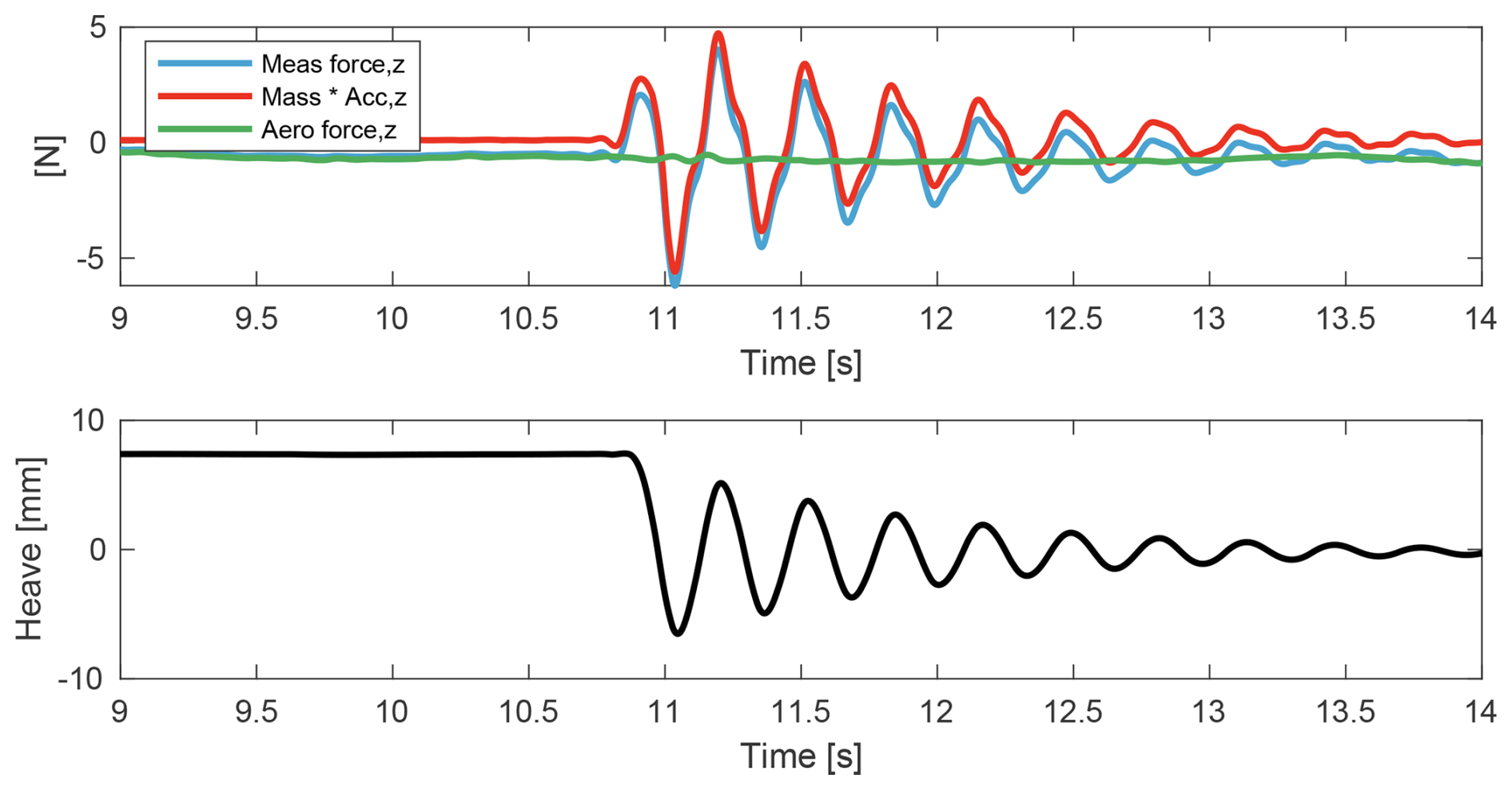
The analysis of the force correction procedure is expanded here, showing it for all directions and for some illustrative cases with wind. In all the following plots, the light blue lines indicate measured force signals, the red lines visualise the correction action, the green lines indicate the estimated aerodynamic force signals, and the black lines show the main DOF motion. The roll case is shown in Fig. A3 and the heave case is shown in Fig. A4. The yaw case in Fig. A5 has no correction action. In the cases with wind in Figs. A6 and A7, the estimated aerodynamic force is not null.
The dataset is accessible upon request to the authors.
FT and AV imagined the scope of the work and designed the experimental campaign. FT developed the experimental setup. FT developed the numerical models and carried out the tests. FT performed the analyses of the results. FT and AV performed the literature review. FT prepared the paper, including contributions from AV, and interpreted the results. AV reviewed the paper.
The contact author has declared that neither of the authors has any competing interests.
Publisher's note: Copernicus Publications remains neutral with regard to jurisdictional claims made in the text, published maps, institutional affiliations, or any other geographical representation in this paper. The authors bear the ultimate responsibility for providing appropriate place names. Views expressed in the text are those of the authors and do not necessarily reflect the views of the publisher.
This research is partially funded by the Dutch National Research Council (NWO) within the HybridLabs project (NWA.1518.22.066) of the Dutch Research Agenda research programme for research along NWA routes by consortia and through the Talent Programme Vidi scheme (project number 19675). The authors would also like to acknowledge Shakthi Thinakaran for her contribution to this work with her master's thesis and her participation in the experimental tests.
This research has been supported by the Nederlandse Organisatie voor Wetenschappelijk Onderzoek (grant nos. NWA.1518.22.066 and 19675).
This paper was edited by Erin Bachynski-Polić and reviewed by three anonymous referees.
Armesto, J. A., Jurado, A., Guanche, R., Couñago, B., Urbano, J., and Serna, J.: TELWIND: Numerical Analysis of a Floating Wind Turbine Supported by a Two Bodies Platform, in: Volume 10: Ocean Renewable Energy, American Society of Mechanical Engineers, ISBN 978-0-7918-5131-9, https://doi.org/10.1115/OMAE2018-77587, 2018. a
Azcona, J., Bouchotrouch, F., González, M., Garciandía, J., Munduate, X., Kelberlau, F., and Nygaard, T. A.: Aerodynamic Thrust Modelling in Wave Tank Tests of Offshore Floating Wind Turbines Using a Ducted Fan, J. Phys. Conf. Ser., 524, 012089, https://doi.org/10.1088/1742-6596/524/1/012089, 2014. a
Azcona, J., Bouchotrouch, F., and Vittori, F.: Low-frequency dynamics of a floating wind turbine in wave tank-scaled experiments with SiL hybrid method, Wind Energy, 22, 1402–1413, https://doi.org/10.1002/we.2377, 2019. a
Bachynski, E. E., Thys, M., Sauder, T., Chabaud, V., and Sæther, L. O.: Real-Time Hybrid Model Testing of a Braceless Semi-Submersible Wind Turbine: Part II – Experimental Results, in: Volume 6: Ocean Space Utilization; Ocean Renewable Energy, American Society of Mechanical Engineers, ISBN 978-0-7918-4997-2, https://doi.org/10.1115/OMAE2016-54437, 2016. a
Bak, C., Zahle, F., Bitsche, R., Kim, T., Yde, A., Henriksen, L. C., Nata-rajan, A., and Hansen, M. H.: Department of Wind Energy I-Report Description of the DTU 10 MW Reference Wind Turbine, DTU Wind Energy, DTU Wind Energy Report-I-0092, 2013. a, b
Bayati, I., Belloli, M., Bernini, L., and Zasso, A.: Wind Tunnel Wake Measurements of Floating Offshore Wind Turbines, Energy Proced., 137, 214–222, https://doi.org/10.1016/j.egypro.2017.10.375, 2017. a
Bayati, I., Facchinetti, A., Fontanella, A., and Belloli, M.: 6-DoF hydrodynamic modelling for wind tunnel hybrid/HIL tests of FOWT: the real-time challenge, in: International Conference on Offshore Mechanics and Arctic Engineering, vol. 51319, p. V010T09A078, American Society of Mechanical Engineers, https://doi.org/10.1115/OMAE2018-77804, 2018a. a
Bayati, I., Facchinetti, A., Fontanella, A., Giberti, H., and Belloli, M.: A wind tunnel/HIL setup for integrated tests of Floating Offshore Wind Turbines, J. Phys. Conf. Ser., 1037, 052025, https://doi.org/10.1088/1742-6596/1037/5/052025, 2018b. a
Belloli, M., Bayati, I., Facchinetti, A., Fontanella, A., Giberti, H., Mura, F. L., Taruffi, F., and Zasso, A.: A hybrid methodology for wind tunnel testing of floating offshore wind turbines, Ocean Eng., 210, https://doi.org/10.1016/j.oceaneng.2020.107592, 2020. a, b, c, d
Bredmose, H., Lemmer, F., Borg, M., Pegalajar-Jurado, A., Mikkelsen, R. F., Larsen, T. S., Fjelstrup, T., Yu, W., Lomholt, A. K., Boehm, L., and Armendariz, J. A.: The Triple Spar campaign: Model tests of a 10 MW floating wind turbine with waves, wind and pitch control, Energy Proced., 137, 58–76, https://doi.org/10.1016/j.egypro.2017.10.334, 2017. a, b
Brodtkorb, P. A., Johannesson, P., Lindgren, G., Rychlik, I., Rydén, J., and Sjö, E.: WAFO-a Matlab toolbox for analysis of random waves and loads, in: ISOPE International Ocean and Polar Engineering Conference, pp. ISOPE–I, isope, 2000. a
Cermelli, C., Aubault, A., Roddier, D., and McCoy, T.: Qualification of a semi-submersible floating foundation for multi-megawatt wind turbines, in: Offshore Technology Conference, OTC-20674, OTC, https://doi.org/10.4043/20674-MS, 2010. a
Cummins, W.: The impulse response function and ship motions, https://dome.mit.edu/handle/1721.3/49049 (last access: 18 March 2026), 1962. a
Doisenbant, G., Boulluec, M. L., Scolan, Y.-M., and Guyot, M.: Application to reduced scale model testing, Wind Engineering, 42, 108–114, 2018. a
Dong, J. and Viré, A.: The aerodynamics of floating offshore wind turbines in different working states during surge motion, Renew. Energ., 195, 1125–1136, https://doi.org/10.1016/j.renene.2022.06.016, 2022. a
Duarte, T., Alves, M., Jonkman, J., and Sarmento, A.: State-Space Realization of the Wave-Radiation Force Within FAST, vol. Volume 8: Ocean Renewable Energy of International Conference on Offshore Mechanics and Arctic Engineering, V008T09A021, https://doi.org/10.1115/OMAE2013-10375, 2013. a
Fontanella, A., Da Pra, G., and Belloli, M.: Integrated Design and Experimental Validation of a Fixed-Pitch Rotor for Wind Tunnel Testing, Energies, 16, https://doi.org/10.3390/en16052205, 2023a. a
Fontanella, A., Facchinetti, A., Daka, E., and Belloli, M.: Modeling the coupled aero-hydro-servo-dynamic response of 15 MW floating wind turbines with wind tunnel hardware in the loop, Renew. Energ., 219, 119442, https://doi.org/10.1016/j.renene.2023.119442, 2023b. a, b, c
Goupee, A. J., Fowler, M. J., Kimball, R. W., Helder, J., and de Ridder, E.-J.: Additional Wind/Wave Basin Testing of the DeepCwind Semi-Submersible With a Performance-Matched Wind Turbine, in: Volume 9B: Ocean Renewable Energy, American Society of Mechanical Engineers, ISBN 978-0-7918-4554-7, https://doi.org/10.1115/OMAE2014-24172, 2014a. a
Goupee, A. J., Koo, B. J., Kimball, R. W., Lambrakos, K. F., and Dagher, H. J.: Experimental comparison of three floating wind turbine concepts, J. Offshore Mech. Arct., 136, https://doi.org/10.1115/1.4025804, 2014b. a
Jiang, Z., Wen, B., Chen, G., Tian, X., Li, J., Ouyang, D., Peng, Z., Dong, Y., and Zhou, G.: Real-time hybrid test method for floating wind turbines: Focusing on the aerodynamic load identification, Journal of Ocean Engineering and Science, 10, 449–461, https://doi.org/10.1016/j.joes.2024.06.002, 2025. a
Jonkman, J. M. and Buhl, M. L.: FAST User's Guide: Technical Report, 2005. a
Krieger, A., Ramachandran, G. K. V., L., V., Gómez Alonso, P., González Almería, G., Berque, J., and Aguirre, G.: LIFES50+ D7.2: Design basis, report, 2015. a
Larsen, T. J. and Hanson, T. D.: A method to avoid negative damped low frequent tower vibrations for a floating, pitch controlled wind turbine, J. Phys. Conf. Ser., 75, https://doi.org/10.1088/1742-6596/75/1/012073, 2007. a
Lemmer, F., Amann, F., Raach, S., and Schlipf Swe, D.: Definition of the SWE-TripleSpar Floating Platform for the DTU 10 MW Reference Wind Turbine, Tech. rep., 2016. a, b, c
Lemmer, F., Raach, S., Schlipf, D., Faerron-Guzmán, R., and Cheng, P. W.: FAST model of the SWE-TripleSpar floating wind turbine platform for the DTU 10 MW reference wind turbine, DaRUS [data set], https://doi.org/10.18419/DARUS-514, 2020. a
Lignarolo, L.: On the turbulent mixing in horizontal axis wind turbine wakes, Ph.D. thesis, Delft University of Technology, 2016. a
Oguz, E., Clelland, D., Day, A. H., Incecik, A., López, J. A., Sánchez, G., and Almeria, G. G.: Experimental and numerical analysis of a TLP floating offshore wind turbine, Ocean Eng., 147, 591–605, https://doi.org/10.1016/j.oceaneng.2017.10.052, 2018. a
Papi, F., Jonkman, J., Robertson, A., and Bianchini, A.: Going beyond BEM with BEM: an insight into dynamic inflow effects on floating wind turbines, Wind Energ. Sci., 9, 1069–1088, https://doi.org/10.5194/wes-9-1069-2024, 2024. a
Ramachandran, G., Vita, L., Krieger, A., and Mueller, K.: Design basis for the feasibility evaluation of four different floater designs, Energy Proced., 137, 186–195, 2017. a
Robertson, A. N., Jonkman, J. M., Goupee, A. J., Coulling, A. J., Prowell, I., Browning, J., Masciola, M. D., and Molta, P.: Summary of Conclusions and Recommendations Drawn From the DeepCwind Scaled Floating Offshore Wind System Test Campaign, vol. Volume 8: Ocean Renewable Energy of International Conference on Offshore Mechanics and Arctic Engineering, V008T09A053, https://doi.org/10.1115/OMAE2013-10817, 2013. a
Ruzzo, C., Muggiasca, S., Malara, G., Taruffi, F., Belloli, M., Collu, M., Li, L., Brizzi, G., and Arena, F.: Scaling strategies for multi-purpose floating structures physical modeling: state of art and new perspectives, Appl. Ocean Res., 108, https://doi.org/10.1016/j.apor.2020.102487, 2021. a
Schulz, C. W., Netzband, S., Özinan, U., Cheng, P. W., and Abdel-Maksoud, M.: Wind turbine rotors in surge motion: new insights into unsteady aerodynamics of floating offshore wind turbines (FOWTs) from experiments and simulations, Wind Energ. Sci., 9, 665–695, https://doi.org/10.5194/wes-9-665-2024, 2024. a
Shi, W., Fu, J., Ren, Z., Jiang, Z., Wang, T., Cui, L., and Li, X.: Real-time hybrid model tests of floating offshore wind turbines: Status, challenges, and future trends, Appl. Ocean Res., 141, https://doi.org/10.1016/j.apor.2023.103796, 2023. a
Taruffi, F., Combette, R., and Viré, A.: Experimental and CFD analysis of a floating offshore wind turbine under imposed motions, J. Phys. Conf. Ser., 2767, 062010, https://doi.org/10.1088/1742-6596/2767/6/062010, 2024a. a
Taruffi, F., Novais, F., and Viré, A.: An experimental study on the aerodynamic loads of a floating offshore wind turbine under imposed motions, Wind Energ. Sci., 9, 343–358, https://doi.org/10.5194/wes-9-343-2024, 2024b. a, b, c, d, e, f, g
Thys, M., Chabaud, V., Sauder, T., Eliassen, L., Sæther, L. O., and Magnussen, B.: Real-Time Hybrid Model Testing of a Semi-Submersible 10 MW Floating Wind Turbine and Advances in the Test Method, in: ASME 2018 1st International Offshore Wind Technical Conference, American Society of Mechanical Engineers, ISBN 978-0-7918-5197-5, https://doi.org/10.1115/IOWTC2018-1081, 2018. a
van Kuik, G. A. M., Peinke, J., Nijssen, R., Lekou, D., Mann, J., Sørensen, J. N., Ferreira, C., van Wingerden, J. W., Schlipf, D., Gebraad, P., Polinder, H., Abrahamsen, A., van Bussel, G. J. W., Sørensen, J. D., Tavner, P., Bottasso, C. L., Muskulus, M., Matha, D., Lindeboom, H. J., Degraer, S., Kramer, O., Lehnhoff, S., Sonnenschein, M., Sørensen, P. E., Künneke, R. W., Morthorst, P. E., and Skytte, K.: Long-term research challenges in wind energy – a research agenda by the European Academy of Wind Energy, Wind Energ. Sci., 1, 1–39, https://doi.org/10.5194/wes-1-1-2016, 2016. a
Viselli, A. M., Goupee, A. J., and Dagher, H. J.: Model Test of a 1:8-Scale Floating Wind Turbine Offshore in the Gulf of Maine1, J. Offshore Mech. Arct., 137, https://doi.org/10.1115/1.4030381, 2015. a
Vittori, F., Azcona, J., Eguinoa, I., Pires, O., Rodríguez, A., Morató, Á., Garrido, C., and Desmond, C.: Model tests of a 10 MW semi-submersible floating wind turbine under waves and wind using hybrid method to integrate the rotor thrust and moments, Wind Energ. Sci., 7, 2149–2161, https://doi.org/10.5194/wes-7-2149-2022, 2022. a
Zhao, Y. S., She, X. H., He, Y. P., Yang, J. M., Peng, T., and Kou, Y. F.: Experimental Study on New Multi-Column Tension-Leg-Type Floating Wind Turbine, China Ocean Eng., 32, 123–131, https://doi.org/10.1007/s13344-018-0014-0, 2018. a