the Creative Commons Attribution 4.0 License.
the Creative Commons Attribution 4.0 License.
 | 21 Dec 2018
Comparison of planetary bearing load-sharing characteristics in wind turbine gearboxes
Zhiwei Zhang
Doug Lucas
In this paper, the planetary load-sharing behavior and fatigue life of different wind turbine gearboxes when subjected to rotor moments are examined. Two planetary bearing designs are compared – one design using cylindrical roller bearings with clearance and the other design using preloaded tapered roller bearings to support both the carrier and planet gears. Each design was developed and integrated into a 750 kW dynamometer tests, the loads on each planet bearing row were measured and compared to finite-element models. Bearing loads were not equally shared between the set of cylindrical roller bearings supporting the planets even in pure torque conditions, with one bearing supporting up to 46 % more load than expected. A significant improvement in planetary bearing load sharing was demonstrated in the gearbox with preloaded tapered roller bearings with maximum loads 20 % lower than the gearbox with cylindrical roller bearings. Bearing life was calculated with a representative duty cycle measured from field tests. The predicted fatigue life of the eight combined planet and carrier bearings for the gearbox with preloaded tapered roller bearings is 3.5 times greater than for the gearbox with cylindrical roller bearings. The influence of other factors, such as carrier and planet bearing clearance, gravity, and tangential pin position error, is also investigated. The combined effect of gravity and carrier bearing clearance was primarily responsible for unequal load sharing. Reducing carrier bearing clearance significantly improved load sharing, while reducing planet clearance did not. Normal tangential pin position error did not impact load sharing due to the floating sun design of this three-planet gearbox.
- Article
(4617 KB) - Full-text XML
- BibTeX
- EndNote


Although the cost of energy from wind has declined tremendously during the past 3 decades (US Department of Energy, 2018), wind power plant operation and maintenance (O&M) costs are higher than anticipated and remain an appreciable contributor to the overall cost of wind energy. Wind power plant O&M averages USD 10 per megawatt hour at recently installed wind plants, accounts for 20 % or more of the wind power purchase agreement price, and generally increases as the wind plant ages (Wiser and Bolinger, 2017). Approximately half of the total wind plant O&M costs are related to wind turbine O&M (Lantz, 2013), and a sizeable portion of these costs is related to the reliability of the wind turbine drivetrain (Kotzalas and Doll, 2010; Greco et al., 2013; Keller et al., 2016).
Most of the wind turbines installed in the United States utilize a geared drivetrain with a multi-stage gearbox including one or more planetary stages. These gearboxes must operate in a challenging, dynamic environment different from other industrial applications (Struggl et al., 2014). In general, wind turbine gearboxes do not achieve their expected design life (Lantz, 2013), even though they commonly meet or exceed the criteria specified in standards in the gear, bearing, and wind turbine industry as well as third-party certifications. Planet bearing failures, although not the most frequent type of failure (Sheng, 2017), are extremely costly because they typically require replacement of the entire gearbox with a large crane and thus merit investigation. In planetary gearboxes, equal load distribution between the planet gears and load distribution is required to achieve the predicted design life. Unequal load sharing between planetary gears due to manufacturing and assembly errors has been extensively examined in the past 3 decades (Winkelmann, 1987; Lamparski, 1995; Predki and Vriesen, 2005; Cooley and Parker, 2014), with analytic models often validated through finite-element models or experimental measurements at fixed locations or even on rotating gearing (Mo et al., 2016; Nam et al., 2016). More recently and specifically for wind turbine gearboxes, the ability of a floating sun gear to absorb the consequences of geometrical imperfections has been studied (Nejad et al., 2015; Iglesias et al., 2016). The effects of gravity and the drivetrain tilt angle on planet gear load-sharing and tooth-wedging behavior were examined (Guo et al., 2014; Qiu et al., 2015). Gravity is an important factor as it introduces fundamental excitations in the rotating carrier frame of planetary gear sets. The effect of carrier bearing clearance on planetary load sharing subject to rotor moments has also been studied (Crowther et al., 2011; LaCava et al., 2013; Guo et al., 2014, 2015). Rotor moments impact planet load sharing, gear and bearing alignment, and bearing contact conditions and stress (Park et al., 2013; Gould and Burris, 2016; Dabrowski and Natarajan, 2017). Steady-state rotor moments and gravity result in a once-per-revolution variation in bearing load in the rotating carrier frame, which both increases fatigue and could cause wear or skidding (Guo et al., 2014; Gould and Burris, 2016). Although it is generally agreed that a three-planet gear set with a floating central member has equal load sharing regardless of manufacturing errors (Cooley and Parker, 2014), in the wind turbine application, bearing clearance, gravity, and rotor moments can in fact cause unequal load sharing between planet gears.
Although load sharing between planetary gears has been examined extensively, the distribution of loads between the two or more bearing rows supporting each planet has not. In this paper, the load-sharing characteristics between the bearing rows supporting the planetary gears of two different wind turbine gearbox designs are examined and compared. This work extends previous works by the authors (LaCava et al., 2013; Guo et al., 2015; Keller et al., 2017a, b) by examining a wind turbine gearbox planetary section supported by preloaded tapered roller bearings (TRBs) in addition to one supported by full complement and typical caged cylindrical roller bearings (CRBs) that operate in clearance. Loads predicted by design tools are compared to test measurements across a wide range of field-measured loading conditions, and the resultant planetary section fatigue life for a duty cycle of a typical turbine is also compared. The physical phenomenon responsible for unequal load sharing of the planet bearings is identified.
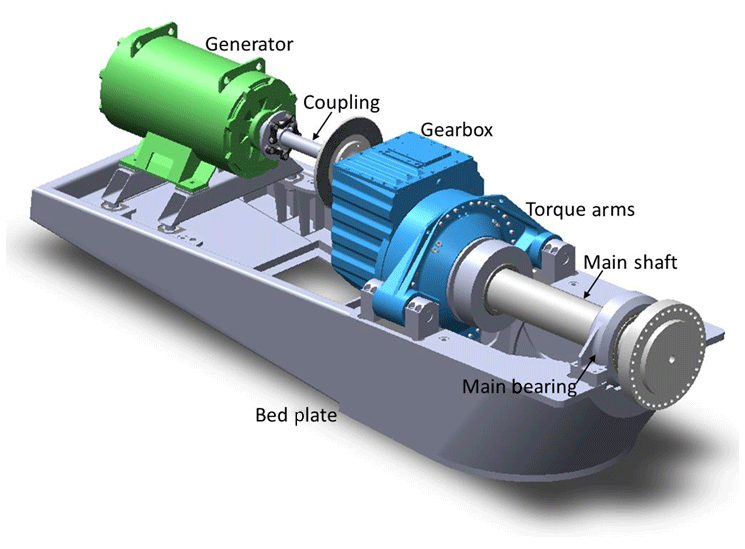
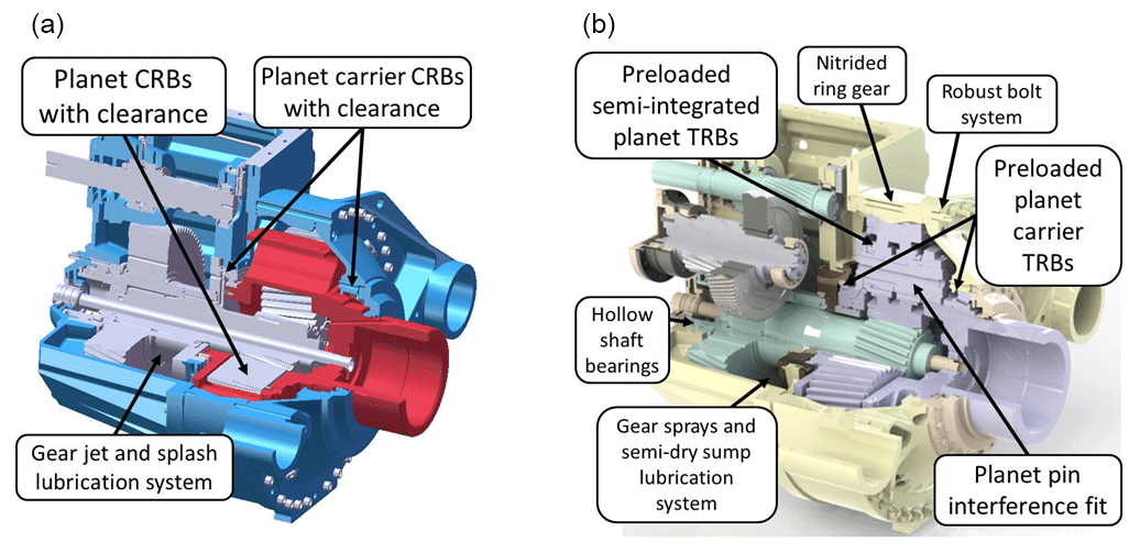
Figure 2Comparison of the GRC gearbox designs featuring CRBs (a) and TRBs (b). Illustration by Romax Technology (b).
The National Renewable Energy Laboratory Gearbox Reliability Collaborative (GRC) has been investigating the root causes of premature wind turbine gearbox failures for over a decade. A modular 750 kW wind drivetrain from a NEG Micon 750/48 wind turbine featuring a three-stage gearbox in an three-point mounted configuration, still representative of most utility-scale drivetrain architectures, has been used for this effort, as shown in Fig. 1. In the three-point mounted configuration, the rotor and main shaft are primarily supported by a double-row spherical roller main bearing. The main shaft is connected to the planet carrier of the gearbox, which is supported by two torque arms that are mounted to the bedplate with elastomeric bushings. The two torque arms, along with the main bearing, provide a total of three points of support. The three-point mounted configuration transfers torque and rotor moments through the gearbox, which is an important design consideration (Guo et al., 2017).
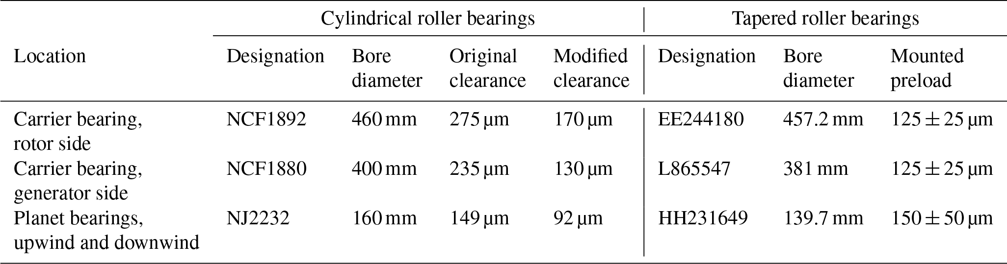
The GRC gearbox design has a single-input planetary stage followed by two parallel-shaft stages. The output shaft of the gearbox is connected to the generator with a flexible coupling. The rated rotor speed is 22.1 rpm, and with a ratio of 81.491, the gearbox increases the output speed to 1800 rpm (Oyague, 2011; Link et al., 2011). The planetary stage features a floating sun to help equalize the load distribution among the three equally spaced planets, accomplished with a hollow low-speed shaft that has an internal spline connection to the sun pinion (Guo et al., 2013). Using this drivetrain and gearbox architecture, the GRC has investigated planetary gear and bearing failure modes and load-sharing characteristics through a dedicated research and test campaign. Two different gearbox designs were purposefully developed, manufactured, and tested. As shown in Fig. 2, their primary difference is the bearing types supporting the carrier and planet bearings. One design features planet CRBs with C3 clearance and full complement carrier CRBs with CN clearance, while the other features planet and carrier TRBs under preload.
In many applications, a small preload, creating a small negative operating clearance, can optimize roller loads and maximize bearing life (Oswald et al., 2012). These preloaded bearings, along with interference-fitted planet pins, improve planet alignments and load-sharing characteristics. A semi-integrated planet bearing design also increases capacity and eliminates outer race fretting. Other than these planetary system changes, including updating gear tooth microgeometry, the gearbox designs are nearly identical. The front and rear housing components, originally from a commercially available Jahnel-Kestermann PSC 1000-48/60 gearbox and with intermediate- and high-speed stage gearing, are used in each gearbox. Physical parameters of the planetary bearings are given in Table 1. The models used to design the gearbox with TRBs indicated that it has over three 3 the planetary stage predicted L10 life compared to the gearbox with CRBs, like the projected increase in fatigue life in other industrial applications (Flamang and Clement, 2003; Lucas, 2005).
In two separate test campaigns, the gearboxes were mounted in the GRC drivetrain and installed in a dynamometer at the National Wind Technology Center, as shown in Fig. 3. Steady-state, constant-speed drivetrain operations were conducted throughout a range of power levels, from offline to the full 750 kW electrical power and 325 kilonewton meter (kNm) input torque. Vertical and lateral forces were applied with hydraulic actuators to an adapter in front of the main bearing, resulting in bending moments up to ±300 kNm measured on the main shaft. This range of moments was derived from measurements on the same drivetrain when installed in an NEG Micon NM 750/48 turbine at an operational wind plant (Link et al., 2011). Unique to the GRC program is that all engineering drawings, models, and resulting test data are publicly available (Keller and Wallen, 2015, 2017).
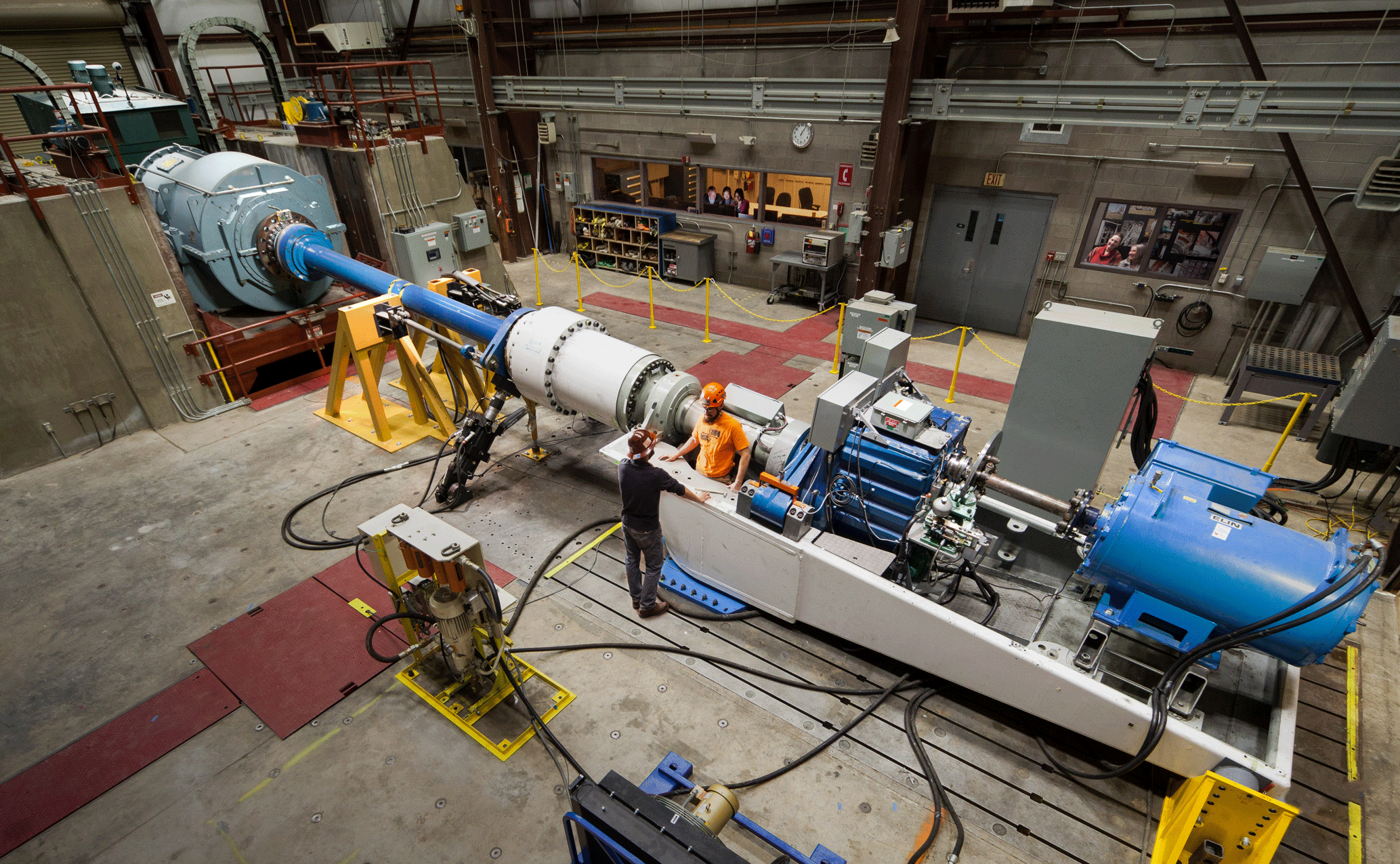
Figure 3Installation of the GRC drivetrain in the dynamometer. Photo by Mark McDade, NREL 32734.
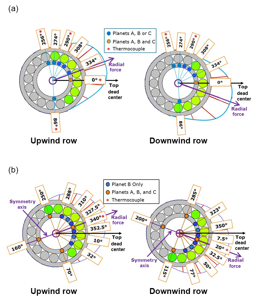
Each gearbox was extensively instrumented, focusing primarily on planetary stage load-sharing characteristics. A total of 36 strain gage pair measurements were evenly placed between the upwind and downwind bearings of the three planets (A, B, and C) for each gearbox. Most of the measurements were in the expected bearing load zones, as shown in Fig. 4. The helical planetary gearing causes an overturning moment on the planets, resulting in a ±20∘ offset of the center of each load zone from the bearing top dead center (TDC). The measurements were made at identical circumferential locations for the upwind and downwind bearings for the gearbox with CRBs. Two measurements were taken along the bearing inner-race width to investigate the axial load distribution between the upwind and downwind bearing rows (Link et al., 2011). Conversely for the gearbox with preloaded TRBs, the measurements focused on the circumferential load distribution with only one axial measurement on each bearing inner race. Additionally, one planet (B) has measurements at 10 circumferential locations per bearing row, 9 of which span the expected load zone. The other two planets (A and C) have measurements at four circumferential locations per bearing row (Keller and Wallen, 2017). The roller load at each measurement location is determined by converting the average strain range with calibration factors determined from dedicated bench tests (van Dam, 2011; Keller and Lucas, 2017). Several thermocouples were also installed on the bearing inner races for each gearbox.
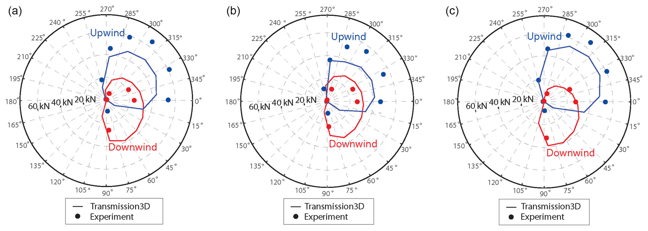
Figure 5Planet CRB load zones with −300 kNm (a), pure torque (b), and +300 kNm (c) pitch moments.
Gearbox models were developed in two different finite-element, commercial software applications to predict planetary loads and load zones. The Transmission3D software application implements a three-dimensional, contact-mechanics model (Transmission3D, 2018). The gearbox is represented with deformable bodies, including the ring gear and gearbox housing, as their flexibility can affect gear misalignment and load-sharing characteristics. Gear and bearing contacts, including piece-wise clearance nonlinearities, are modeled with a hybrid of finite elements to predict far-field displacements and a Green's function model to predict displacements in the contact region. Known bearing clearances, preload, and pin position errors were included in the model. The RomaxWind software application implements a beam finite-element representation of shafts and a solid finite-element representation of the gearbox housing, gear blanks, carrier, and torque arms (RomaxWind, 2018). The gears and bearings were modeled with semi-analytical formulations that account for misalignment, area of contact under load, microgeometry, radial and axial clearances, and material properties. Static nonlinear analysis is performed for prescribed loading conditions, and the global deflections are solved simultaneously. Additionally, bearing modified L10 fatigue life calculations are made for a predetermined drivetrain torque, thrust, and pitch and yaw moment spectrum (Keller et al., 2017a).
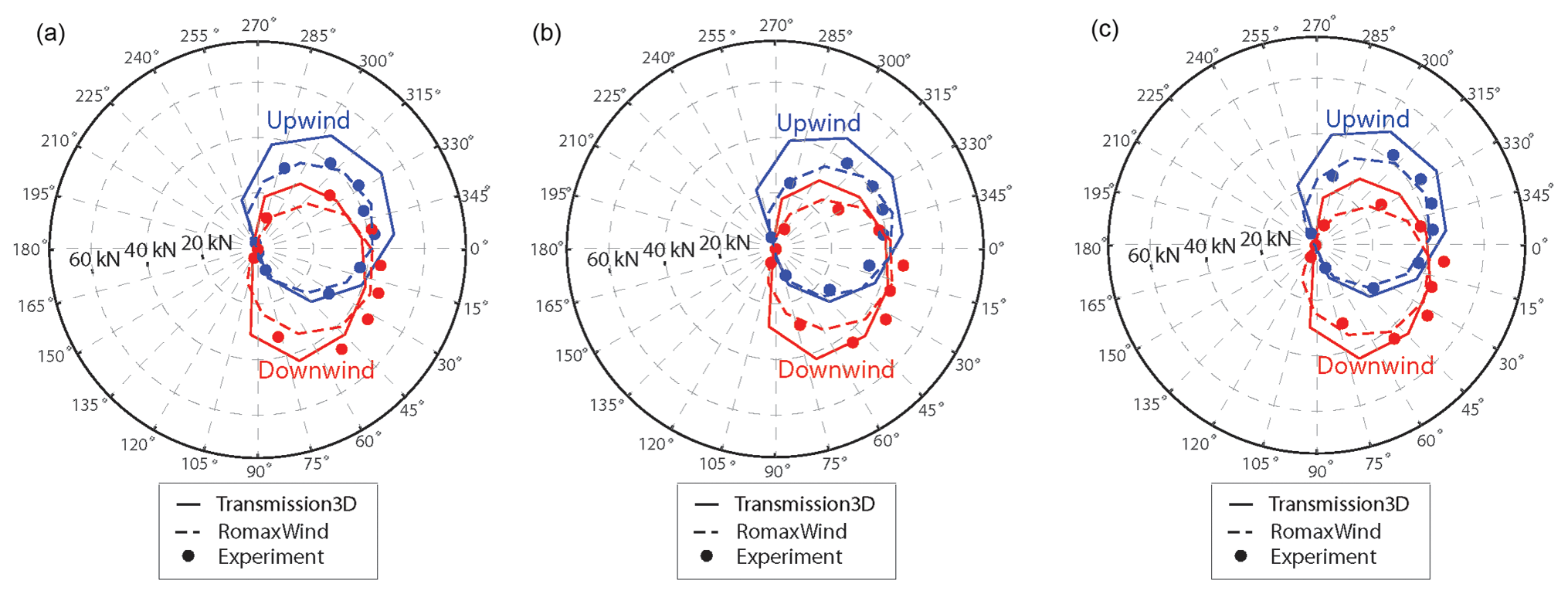
Figure 6Planet TRB load zones with −300 kNm (a), pure torque (b), and +300 kNm (c) pitch moments.
In this section, the planetary bearing loads and load-sharing characteristics predicted by the models and measured in dynamometer tests are compared for both gearboxes. The fatigue life of planetary bearing designs is also calculated. Finally, several parametric design studies are examined for the gearbox with CRBs to understand the factors contributing to its load-sharing characteristics.
4.1 Planet bearing load zones
In this section, the bearing load zones for each gearbox are compared when the planet is at the bottom of the ring gear. The load zones for the pure torque condition are compared to those for the highest pitch moments. As shown in Fig. 5, the upwind planet CRB load zone increases in size as the applied pitch moment increases. In general, the upwind planet bearing supports up to twice the load of the downwind bearing. The downwind planet CRB load zone is not significantly affected by the applied pitch moment. The theoretical maximum roller load (Harris and Kotzalas, 2006) of approximately 45 kilonewtons (kN) for these bearings generally correlates with the measurements and model predictions.

In contrast, as shown in Fig. 6, the planet TRB load zones maintain their size and orientation regardless of the applied pitch moment. The more circular shape of the load zones reflects the preload in the bearings and the rigidity of the planetary system in general. The measured load zone magnitudes and orientations correlate well with the predictions, including the ±20∘ offset of the load zone from TDC. The theoretical maximum roller load (Harris and Kotzalas, 2006), also approximately 45 kN, again correlates with the measurements and predictions. The RomaxWind model assumes rigid bearing races, while Transmission3D includes the flexibility of the races. This results in a more circular load zone prediction for RomaxWind compared to an elliptical load zone for Transmission3D.
4.2 Planet bearing loads
The upwind and downwind planet bearing loads can be calculated for each gearbox. For the instrumented CRBs, a direct calibration factor is used to determine the total bearing load (van Dam, 2011; Harris and Kotzalas, 2006) from only the TDC measurement. For the instrumented TRBs, a spline fit is then used to map the entire load zone and determine the total bearing load (Keller and Lucas, 2017; Keller et al., 2017b). The total load supported by both bearings, which is the vector summation of the upwind and downwind bearing loads, can also be calculated.
Figure 7 compares the measured and predicted loads nondimensionalized by the assumed load (i.e., one-sixth or one-third of the load at the planet center resulting from input torque) over a complete revolution of the planet carrier for the pure torque condition. The 0∘ location indicates the planet is at the top of the ring gear in its rotation and the 180∘ location is at the bottom of the ring gear, which is the same position shown in Figs. 5 and 6. The CRB loads fluctuate over the rotation and are also out of phase because of the combined effect of planet and carrier bearing clearances, gravity, and the resulting gear misalignment (LaCava et al., 2013). The maximum measured load carried by the upwind bearing is 1.43, or 43 % more than the assumed load. The minimum measured load carried by the downwind bearing is only 0.61, or 39 % less than the assumed load. In this condition, the upwind bearing is accumulating more fatigue than expected; conversely, the downwind bearing has an increased risk of skidding for a portion of the carrier rotation. Because the bearing loads are nearly 180∘ out of phase, there is much less fluctuation in the total load than the individual row loads. The maximum total measured bearing load is only 6 % greater than assumed. The planet TRB loads are much more consistent over the carrier rotation due to the preload in the bearings and, to some extent, the interference-fitted planet pins that also reduce misalignment. The maximum and minimum measured row loads are only 12 % different than assumed, whereas the maximum measured total bearing load is only 1 % more than assumed. There is good agreement between these measured loads and those predicted by Transmission3D for both gearboxes.
In contrast, Fig. 8 compares the same loads but with a large negative pitch moment. The measured upwind CRB load is relatively constant over the rotation but 25 % greater than assumed. The downwind load behavior is very similar to the pure torque condition. The net effect is that the total measured bearing load fluctuates slightly more than the pure torque condition and 15 % more than assumed. The measured TRB loads again fluctuate very little – only 8 % for the downwind row and 2 % for the total bearing load.
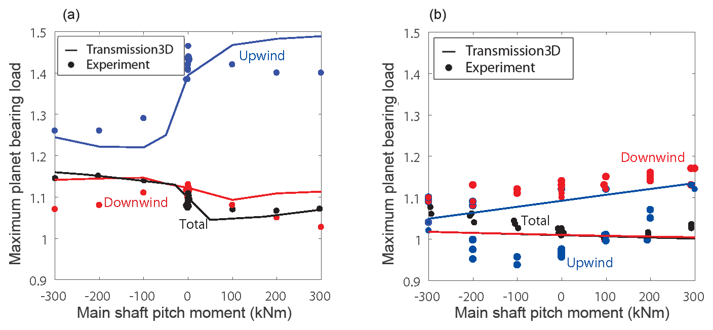
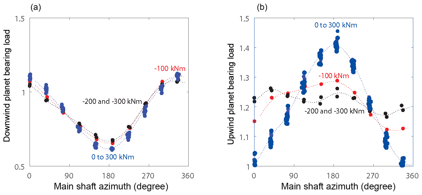
Figure 9 summarizes the measured upwind and downwind planet CRB loads for all the pitch moment cases. The pitch moment changes the upwind bearing loads significantly; however, it does not affect the downwind bearing loads at all. The behavior of the upwind bearing loads can be separated into three categories. Pure torque and positive pitch moments all essentially have the same effect, resulting in the largest variation over the carrier rotation and overall magnitude in the upwind bearing load. Conversely, pitch moments beyond −200 kNm elevate the mean upwind bearing load with much less fluctuation over the carrier rotation. The −100 kNm pitch moment case is a transition between these two categories.
The bearing loads shown in these figures contain both a constant difference from the assumed load and a fluctuating component. The loads are not equally shared in practice. The constant difference is a result of deformations, displacements, and manufacturing deviations causing consistently higher loads on one planet than the others (Cooley and Parker, 2014). The fluctuating component is a result of the rotor moments and gravity, exacerbated by planet and carrier bearing clearances and resulting in misalignment in the gearbox with the CRBs, causing a once-per-revolution load variation over the carrier rotation (Guo et al., 2015).
4.3 Planet bearing load sharing
The accurate estimation of planet bearing loads is a crucial step in calculating the planetary load-sharing factor, also called the planetary mesh load factor (Kγ). Ideally, all planets share torque equally and the planetary mesh load factor equals 1. However, because of positional-type errors and variations in tooth stiffness, International Electrotechnical Commission standard 61400-4 assumes this factor is 1.1 for three-planet wind turbine gearboxes. In this study, the maximum load throughout the main shaft rotation shown in Figs. 7–9, which accounts for both constant load differences and the fluctuating load from gravity and rotor moments, is examined for comparison to this assumption.
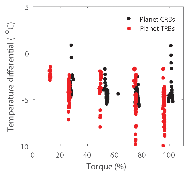
Figure 14Differential between the gearbox sump temperature and the average of planet bearing inner-ring temperatures.
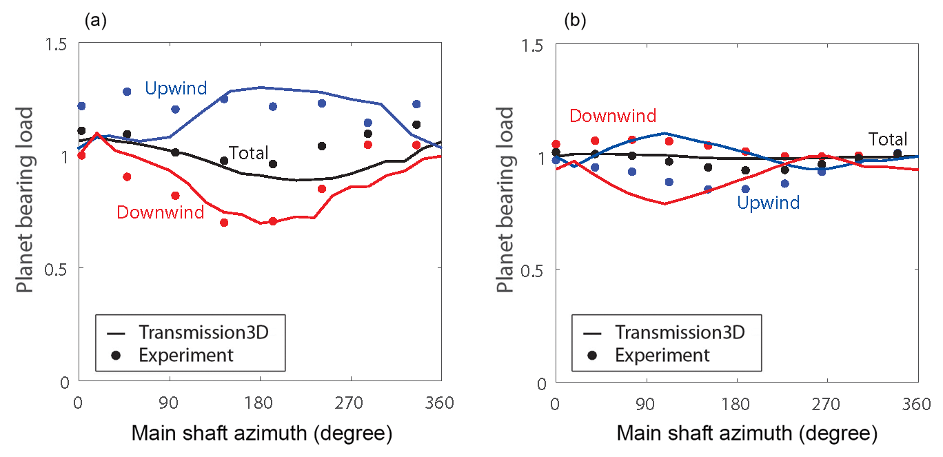
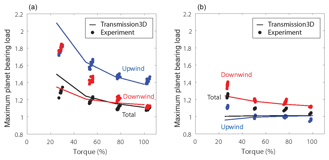
Figure 10 compares the maximum individual bearing row load and maximum total bearing load for both gearboxes over the complete range of pitch moments. The maximum total measured CRB load ranges from 1.07 in pure torque to just over 1.15 for large negative pitch moments, very close to the assumed planetary mesh load factor of 1.1.
However, as shown previously, the measured CRB load carried by the upwind bearing far exceeds this, reaching 1.43 on average and as high as 1.46 in one test. Counterintuitively, this highest load occurs in the pure torque condition and is not affected by increasing the pitch moment, also as demonstrated in Fig. 9. The upwind-measured CRB load does decrease with negative pitch moments; however, it never falls below 1.26. The wide variation in the maximum CRB load can be contrasted with the consistency in the maximum TRB load. In general, the maximum TRB loads are all much closer to the assumed planetary mesh load factor of 1.1. The maximum measured downwind TRB load is 1.13 in pure torque and no more than 1.17 even for a large positive pitch moment – much lower than the maximum CRB load. A significant reduction of the maximum loads and improvement in load sharing was achieved with the design changes in the gearbox with TRBs.
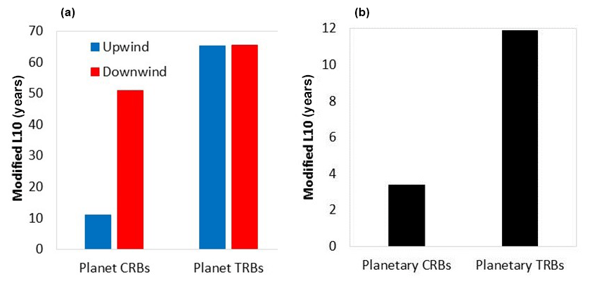

Figure 16Effect of carrier (a) and planet (b) bearing clearance on maximum planet CRB loads.
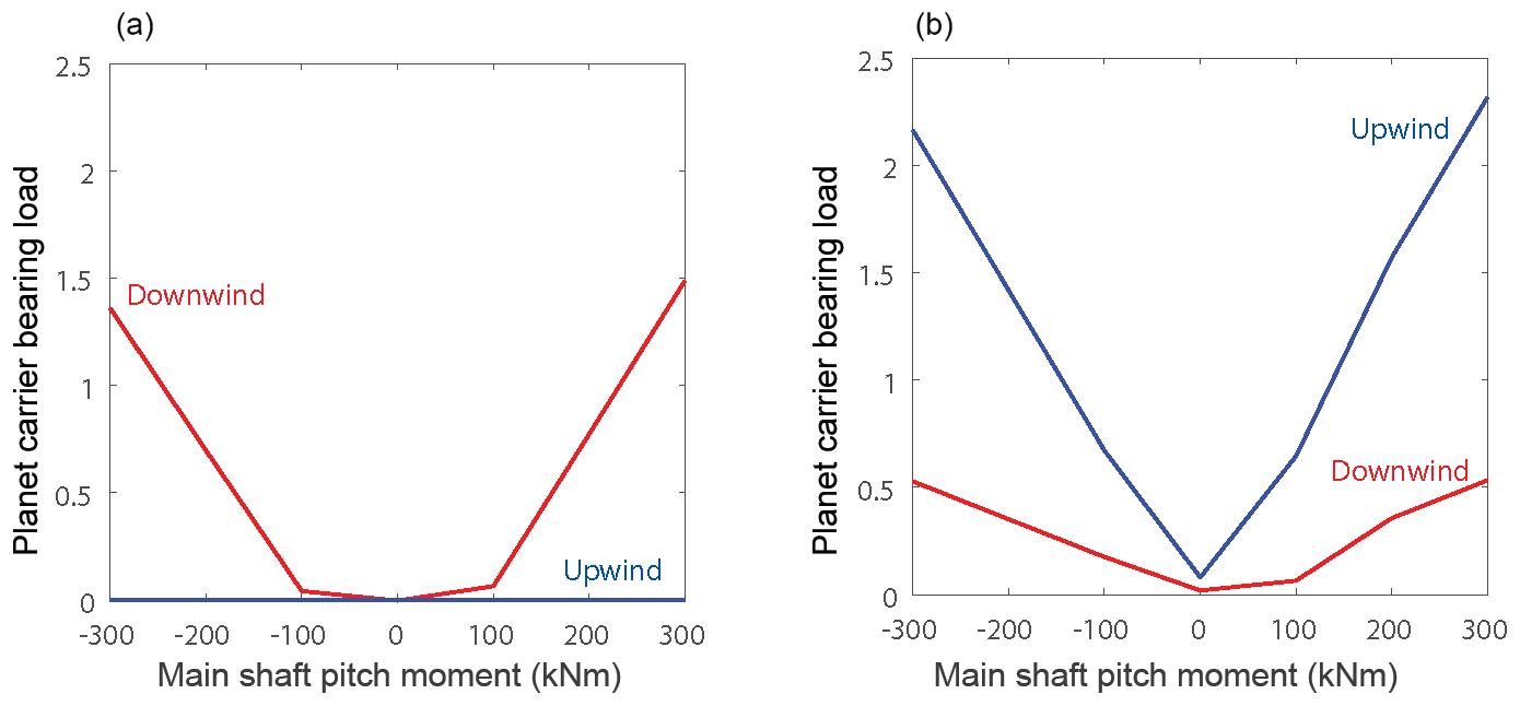
To better understand the planet bearing load-sharing behavior shown in Fig. 10, the effect of pitch moments on carrier bearing loads is explored in Fig. 11. Here only the predicted loads from the model are available; measurements of the carrier bearing loads were not acquired in tests. Carrier bearing loads are also nondimensionalized by the average of the assumed total planet bearing load. Beyond a ±100 kNm pitch moment, the downwind carrier CRB load increases, while the planet CRB load does not. The downwind carrier CRB essentially supports all the additional load. Within a ±100 kNm pitch moment, the planet CRBs carry any load, while the carrier CRBs are both unloaded. For this gearbox, the upwind carrier CRB does not carry any load regardless of the pitch moment. This behavior is a direct result of the relative clearances of all the carrier and planet CRBs. In contrast, because of their preloaded condition both the upwind and downwind carrier TRBs support loads for any applied pitch moment. It is clear from Figs. 10 and 11 that for the gearbox with CRBs, pitch moments can relieve the gravity load from the main shaft and planetary system from the downwind carrier CRB and shift it to the planet CRBs. However, for the gearbox with TRBs, pitch moments are essentially entirely reacted by the carrier bearings. In the three-point mount drivetrain configuration, the carrier bearing is expected to be part of the load path from the wind turbine rotor to the bedplate. In this ideal situation, the planetary gear system carries only torque and is not impacted by other loads, resulting in improved load sharing between planets and upwind and downwind rows. From this analysis, the planet carrier TRBs are carrying the moment loads as expected, whereas the planet carrier CRBs are not.
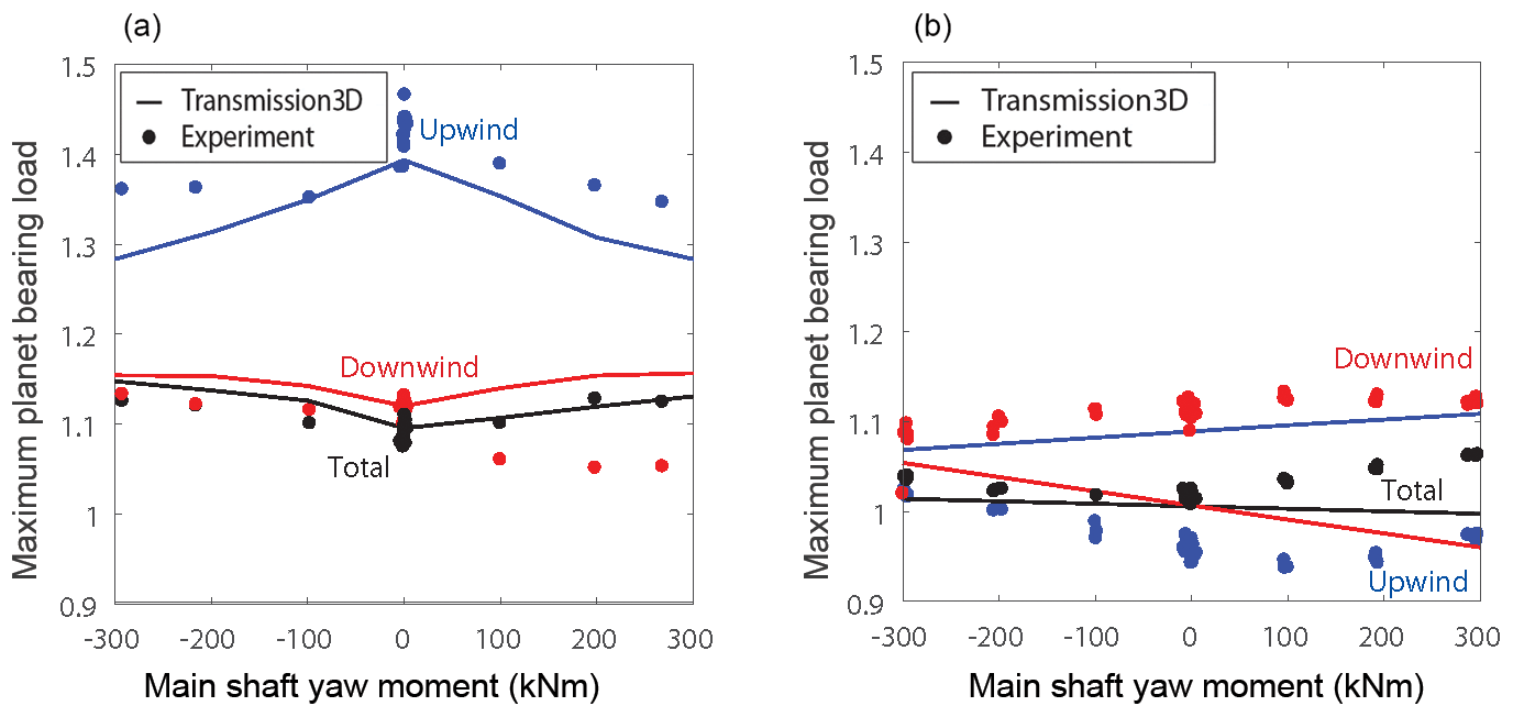
For comparison to pitch moments, Fig. 12 shows the planet loads over the full range of yaw moments for both gearboxes. The maximum upwind CRB loads occur again in pure torque conditions. Both positive and negative yaw moments decrease the maximum upwind CRB load slightly; however, the measured load remains above 1.35. The total measured bearing load follows a more intuitive pattern, in which it is a minimum of 1.08 at pure torque and increases slightly to 1.13 with either positive or negative yaw moments. Yaw moments have little effect on any of the TRB loads. The maximum measured load of 1.13 occurs for the downwind bearing for a positive yaw moment.
Since the largest disparity in load sharing is evident even in pure torque conditions, Fig. 13 examines the maximum individual bearing row load and maximum total bearing load for both gearboxes over the complete range of pure torque conditions tested. Generally, the load increases as torque decreases, although it increases more for the CRBs than the TRBs. The maximum measured total planet bearing load increases from approximately 1.1 at full torque to 1.3 at 25 % torque for both gearboxes. However, the measured CRB load carried by the upwind bearing increases from 1.43 on average in pure torque to as high as 1.85 at 25 % torque. In contrast, the maximum measured downwind TRB load increases from 1.13 in pure torque to just 1.40 at 25 % torque.
As shown in this section, the load-sharing characteristics of the planet TRBs were significantly improved compared to the planet CRBs. However, the use of preload in these bearings does raise the question of their temperature characteristics. The measurements from the thermocouples on the bearing inner races for each gearbox, with respect to the gearbox sump temperature, are examined in Fig. 14. In this figure, the average of all thermocouples on each of the planets is examined for the full range of gearbox operating torque and applied moments. The planet bearing temperatures are approximately 5 ∘C cooler than the sump temperatures for both gearboxes. There is little to no difference in the temperature of the planet bearing inner races between the two gearboxes and thus most likely little to no impact on the gearbox efficiency. This is not necessarily a surprise as the planets are spinning at a relatively low speed compared to the bearings supporting the intermediate-stage and 1800 rpm output shaft of the gearbox. These higher-speed bearings generate significantly more heat and cause the gearbox sump temperature to be higher than the planet bearing operating temperature. For reference, the absolute temperatures of the planet bearings for each gearbox were in the range of 50 to 65 ∘C, while the gearbox sump temperature typically ranged from 55 to 70 ∘C.
4.4 Planet bearing fatigue life
The predicted planetary fatigue life for each gearbox was calculated using a representative drivetrain torque and pitch and yaw moment spectrum derived from field measurements (Keller et al., 2017b). The modified bearing L10 life was calculated per Deutsches Institut für Normung International Organization for Standardization 281 Beiblatt 4 (now superseded by International Organization for Standardization technical specification 16281), including a systems life modification factor. As shown in Fig. 15, the average fatigue life of the upwind planet bearing was increased by a factor of 6 using the TRBs when compared to the CRBs, in addition to a smaller life extension for both the upwind and downwind planet bearings due to the larger bearing capacity in the semi-integrated design. The modified L10 life for the eight total planetary bearings (all six planet bearings and two carrier bearings) is also shown, combined using a Weibull slope of 1.125 (Zaretsky et al., 2007). The planetary stage bearing predicted fatigue life has been increased by a factor of 3.5 using the TRBs when compared to the CRBs. The overall planetary bearing stage life is driven by the lowest-life components, which in this case are the planetary bearings in both gearboxes. The carrier bearings have a much longer fatigue life and thus are not shown individually.
4.5 Parametric studies
The previous section examined planetary load-sharing characteristics in detail. The upwind and downwind planet bearing loads were not shared equally in the gearbox with CRBs, even in pure torque conditions. In this section, the major factors responsible for the disturbed load sharing in this gearbox are examined through parametric studies of bearing clearances, gravity, and pin position error.
4.5.1 Effect of bearing clearances
The planet CRB loads were predicted with reduced clearance settings in the carrier and planet CRBs individually, as listed in Table 1, for comparison to the original model clearances. As shown in Fig. 16, reducing the carrier CRB clearance from CN to C2 resulted in a noticeable improvement in load-sharing characteristics for both the upwind and downwind bearings, especially for positive pitch moments. For example, the predicted upwind CRB load decreases from 1.49 to 1.22 at a +300 kNm pitch moment, a reduction of 18 %. In contrast, reducing the planet CRB clearance from C3 to CN did not significantly reduce the upwind planet CRB loads for positive pitch moments, and it increased the downwind planet CRB loads.
4.5.2 Effect of gravity
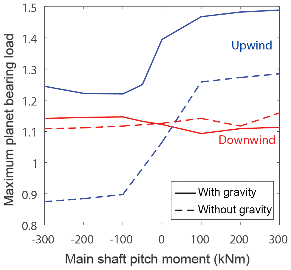
As shown previously, the interplay between the gravity load from the main shaft and planetary system and the pitch moment has a significant effect on both the planet and carrier CRB loads. Figure 17 examines this further by eliminating gravity from the model. Gravity has a significant influence on the planet CRB loads, such as the effect of carrier CRB clearance. Without gravity, the upwind planet CRB load is reduced dramatically anywhere from 0.20 to 0.37 over the entire range of pitch moments, including a reduction from 1.40 to 1.07 at pure torque. The effect of gravity on the downwind planet CRB load is small. The effects of gravity, planetary clearances, and nontorque loads on three-point mounted wind turbine gearboxes are unavoidable and should be considered in their design. The effect of gravity on planet bearing loads can be mitigated by using carrier bearings with reduced clearances if possible.
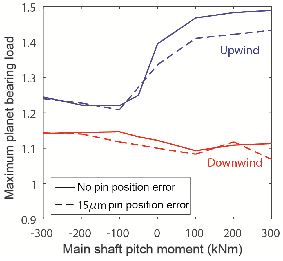
4.5.3 Effect of pin position error
Tangential pin position error is one of the more common manufacturing deviations that is known to affect planetary load sharing (Cooley and Parker, 2014). In this parametric study, the effect of a 15 µm tangential pin position error – a magnitude commonly considered in other applications (Singh, 2009) – on the load sharing of the gearbox with CRBs is assessed. As shown in Fig. 18, the pin position error changes the upwind planet CRB loads for only positive pitch moments by less than 4 %. This effect is much smaller than the load fluctuations caused by other factors, which agrees with analytical results (Singh, 2009). It does not significantly change the upwind planet CRB loads in pure torque, negative pitch moments, or downwind CRB loads. Ideally, pin position error should not disturb load sharing with an adequately floating sun for a three-planet gearbox such as the GRC test article.
This study compared two wind turbine gearbox planetary bearing system designs, a conventional design representing most of the gearboxes used in three-point mounted drivetrains and a new design tailored for increased planetary bearing fatigue life. These two designs differ in the choice of carrier and planet bearings. The first design uses planet CRBs with clearance and the latter utilizes preloaded TRBs. Both gearboxes were designed, built, and instrumented and then tested in a dynamometer under the same set of controlled loading conditions, including pitch and yaw moments. The resulting planet bearing load measurements were correlated with predictions from finite-element models of both gearboxes.
The gearbox design using CRBs with clearance did not demonstrate equal load sharing between the planet CRBs, with one bearing supporting up to 46 % more load than expected. This unequal load sharing occurred, counterintuitively, in pure torque conditions and for positive pitch moments. The gearbox design with preloaded TRBs demonstrated improved planetary load-sharing characteristics compared to the gearbox with CRBs. The preloaded TRBs significantly reduced the planet bearing loads from a maximum of 1.46 to 1.17, a 20 % reduction, in pure torque conditions. Furthermore, pitch and yaw moments did not significantly affect the upwind and downwind TRB row loads. Parametric studies indicate that the unequal load sharing in the gearbox with CRBs is primarily a result of the combined effects of gravity and pitch and yaw moments, and bearing clearances and can be substantially improved by reducing clearance in the carrier bearings. This reduction and equalization in planet bearing loads, along with slightly larger capacity bearings through a semi-integrated design, resulted in a modified L10 life 3.5 times greater for the gearbox with preloaded TRBs than for the gearbox with CRBs.
Data presented in this work is publicly available at https://doi.org/10.7799/1254154 (Keller and Wallen, 2015) and https://doi.org/10.7799/1337868 (Keller and Wallen, 2017).
JK led the design and validation effort and development of the manuscript with contributions from the co-authors. YG performed the modeling, processed experimental data, and validated the model using experimental results. ZZ led the design of the gearbox with tapered roller bearings, and conducted the RomaxWind and lifing analyses. DL designed and provided purpose-designed and instrumented planet gears and tapered roller bearings.
The authors declare that they have no conflict of interest.
The views expressed in the article do not necessarily represent the views of the DOE or the US Government. The US Government retains and the publisher, by accepting the article for publication, acknowledges that the US Government retains a nonexclusive, paid-up, irrevocable, worldwide license to publish or reproduce the published form of this work, or allow others to do so, for US Government purposes.
This work was authored in part by the National Renewable Energy Laboratory
operated by the Alliance for Sustainable Energy, LLC, for the US Department
of Energy (DOE) under contract no. DE-AC36-08GO28308. Funding was provided by
the US Department of Energy Office of Energy Efficiency and Renewable Energy
Wind Energy Technologies.
Edited by: Michael
Muskulus
Reviewed by: Dirk Strasser, Henk Polinder, and Anand
Natarajan
Cooley, C. G. and Parker, R.: A review of planetary and epicyclic gear dynamics and vibrations research, Appl. Mech. Rev., 66, 040804, https://doi.org/10.1115/1.4027812, 2014.
Crowther, A., Ramakrishnan, V., Zaidi, N. A., and Halse, C.: Sources of time-varying contact stress and misalignments in wind turbine planetary sets, Wind Energy, 14, 637–651, https://doi.org/10.1002/we.447, 2011.
Dabrowski, D. and Natarajan, A.: Identification of loading conditions resulting in roller slippage in gearbox bearings of large wind turbines, Wind Energy, 20, 1365–1387, https://doi.org/10.1002/we.2098, 2017.
Flamang, P. and Clement, P.: Stresses and load distribution factors in bearings: a tool to compare bearing alternatives, in: Dresdner Maschinenelemente Kolloquium, Dresden, Germany, 23–24 September 2003, 289–301, 2003.
Gould, B. J. and Burris, D. L.: Effects of wind shear on wind turbine rotor loads and planetary bearing reliability, Wind Energy, 19, 1011–1021, https://doi.org/10.1002/we.1879, 2016.
Greco, A., Sheng, S., Keller, J., and Erdemir, A.: Material wear and fatigue in wind turbine systems, Wear, 302, 1583–1591, https://doi.org/10.1016/j.wear.2013.01.060, 2013.
Guo, Y., Keller, J., Errichello, R., and Halse, C.: Gearbox reliability collaborative analytic formulation for the evaluation of spline couplings, NREL/TP-5000-60637, National Renewable Energy Laboratory, Golden, CO, 2013.
Guo, Y., Keller, J., and Parker, R. G.: Nonlinear dynamics and stability of wind turbine planetary gear sets under gravity effects, Eur. J. Mech. A, 47, 45–57, https://doi.org/10.1016/j.euromechsol.2014.02.013, 2014.
Guo, Y., Keller, J., and LaCava, W.: Planetary gear load sharing of wind turbine drivetrains subjected to non-torque loads, Wind Energy, 18, 757–768, https://doi.org/10.1002/we.1731, 2015.
Guo, Y., Parsons, T., Dykes, K., and King, R.N.: A systems engineering analysis of three-point and four-point wind turbine drivetrain configurations, Wind Energy, 20, 537–550, https://doi.org/10.1002/we.2022, 2017.
Harris, T. and Kotzalas, M.: Essential Concepts of Bearing Technology, Fifth Edition, Taylor & Francis, Boca Raton, FL, 2006.
Iglesias, M., Fernandez del Rincon, A., de-Juan, A., Garcia, P., Diez-Ibarbia, A., and Viadero, F.: Planetary transmission load sharing: manufacturing errors and system configuration study, Mech. Mach. Theory, 111, 21–38, https://doi.org/10.1016/j.mechmachtheory.2016.12.010, 2017.
Keller, J. and Lucas, D.: Gearbox reliability collaborative gearbox 3 planet bearing calibration, NREL/TP-5000-67370, National Renewable Energy Laboratory, Golden, CO, 2017.
Keller, J. and Wallen, R.: Gearbox reliability collaborative phase 3 gearbox 2 test report, NREL/TP-5000-63693, National Renewable Energy Laboratory, Golden, CO, https://doi.org/10.7799/1254154, 2015.
Keller, J. and Wallen, R.: Gearbox reliability collaborative phase 3 gearbox 3 test report, NREL/TP-5000-67612, National Renewable Energy Laboratory, Golden, CO, https://doi.org/10.7799/1337868, 2017.
Keller, J., Sheng, S., Cotrell, J., and Greco, A.: Wind turbine drivetrain reliability collaborative workshop – a recap, NREL/OT-5000-66593, National Renewable Energy Laboratory, Golden, CO, 2016.
Keller, J., Guo, Y., Zhang, Z., and Lucas, D.: Planetary load sharing in three-point mounted wind turbine gearboxes: a design and test comparison, NREL/TP-5000-67394, National Renewable Energy Laboratory, Golden, CO, 2017a.
Keller, J., Guo, Y., Zhang, Z., and Lucas, D.: Planetary load sharing in three-point mounted wind turbine gearboxes: a design and test comparison, NREL/PR-5000-68021, National Renewable Energy Laboratory, Golden, CO, 2017b.
Kotzalas, M. N. and Doll, G. L.: Tribological advancements for reliable wind turbine performance, Philos. T. R. Soc., 368, 4829–4850, https://doi.org/10.1098/rsta.2010.0194, 2010.
LaCava, W., Xing, Y., Marks, C., Guo, Y., and Moan, T.: Three-dimensional bearing load share behaviour in the planetary stage of a wind turbine gearbox, IET Renew. Power Gen., 7, 359–369, https://doi.org/10.1049/iet-rpg.2012.0274, 2013.
Lamparski, C.: Einfache berechnungsgleichungen für lastüberhöhungen in leichtbau-planetengetrieben, Ruhr-Universität Bochum, 246 pp., 1995.
Lantz, E.: Operations expenditures: historical trends and continuing challenges, NREL/PR-6A20-58606, National Renewable Energy Laboratory, Golden, CO, 2013.
Link, H., LaCava, W., van Dam, J., McNiff, B., Sheng, S., Wallen, R., McDade, M., Lambert, S., Butterfield, S., and Oyague, F.: Gearbox reliability collaborative project report: findings from phase 1 and phase 2 testing, NREL/TP-5000-51885, National Renewable Energy Laboratory, Golden, CO, 2011.
Lucas, D.: Planet pac: increasing epicyclic power density and performance through integration, in: AGMA Fall Technical Meeting Proceedings, Detroit, MI, 16–18 October 2005, AGMA 05FTM18, 2005.
Mo, S., Zhang, Y., Wu, Q., Matsumura, S., and Houjoh, H.: Load sharing behavior analysis method of wind turbine gearbox in consideration of multiple-errors, Renew. Energ., 97, 481–491, https://doi.org/10.1016/j.renene.2016.05.058, 2016.
Nam, J. S., Park, Y. J., Han, J. W., Nam, Y. Y., and Lee, G. H.: The effects of non-torque loads on a three-point suspension gearbox for wind turbines, Int. J. Energ. Res., 40, 618–631, https://doi.org/10.1002/er.3373, 2016.
Nejad, A., Xing, Y., Guo, Y., Keller, J., Gao, Z., and Moan, T.: Effects of floating sun gear in a wind turbine's planetary gearbox with geometrical imperfections, Wind Energy, 18, 2105–2120, https://doi.org/10.1002/we.1808, 2015.
Oswald, F. B., Zaretsky, E. V., and Poplawski, J. V.: Effect of internal clearance on load distribution and life of radially loaded ball and roller bearings, Tribol. T., 55, 245–265, https://doi.org/10.1080/10402004.2011.639050, 2012.
Oyague, F.: Gearbox reliability collaborative description and loading, NREL/TP-5000-47773, National Renewable Energy Laboratory, Golden, CO, 2011.
Park, Y., Lee, G., Song, J., and Nam, Y.: Characteristic analysis of wind turbine gearbox considering non-torque loading, J. Mech. Design, 135, 044501, https://doi.org/10.1115/1.4023590, 2013.
Predki, W. and Vriesen, J. W.: Calculating gear tooth corrections for planetary gears: theoretical basis and practical benefit, in: VDI Berichte, International conference on gears: Europe invites the world, Munich, Germany, 311–326, 2005.
Qiu, X., Han, Q., and Chu, F.: Load-sharing characteristics of planetary gear transmission in horizontal axis wind turbines, Mech. Mach. Theory, 92, 391–406, https://doi.org/10.1016/j.mechmachtheory.2015.06.004, 2015.
RomaxWind: available at: http://www.romaxtech.com/software/romaxwind, last access: 18 April 2018.
Sheng, S.: Wind turbine gearbox reliability database, condition monitoring, and operation and maintenance research update, NREL/PR-5000-68347, National Renewable Energy Laboratory, Golden, CO, 2017.
Singh, A.: Load sharing behavior in epicyclic gears: physical explanation and generalized formulation, Mech. Mach. Theory, 45, 511–530, https://doi.org/10.1016/j.mechmachtheory.2009.10.009, 2010.
Struggl, S., Berbyuk, V., and Johansson, H.: Review on wind turbines with focus on drive train system dynamics, Wind Energy, 18, 567–590, https://doi.org/10.1002/we.1721, 2014.
Transmission3D: available at: http://ansol.us/Products/TX3/, last access: 18 April 2018.
Winkelmann, L.: Lastverteilung an planetenradgetrieben, Ruhr-Universität Bochum, 449 pp., 1987.
Wiser, R. and Bolinger, M.: 2016 wind technologies market report, DOE/GO-10217-5033, US Department of Energy, Washington, DC, 2017.
US Department of Energy: Wind vision: a new era for wind power in the United States, available at: http://energy.gov/sites/prod/files/2015/03/f20/wv_full_report.pdf, last access: 28 November 2018.
van Dam, J.: Gearbox reliability collaborative bearing calibration, NREL/TP-5000-47852, National Renewable Energy Laboratory, Golden, CO, 2011.
Zaretsky, E. V., Lewicki, D. G., Savage, M., and Vleck, B. L.: Determination of turboprop reduction gearbox system fatigue life and reliability, Tribol. T., 50, 507–516, https://doi.org/10.1080/10402000701613799, 2007.