the Creative Commons Attribution 4.0 License.
the Creative Commons Attribution 4.0 License.
 | 07 Jul 2020
On the velocity at wind turbine and propeller actuator discs
Gijs A. M. van Kuik
The first version of the actuator disc momentum theory is more than 100 years old. The extension towards very low rotational speeds with high torque for discs with a constant circulation became available only recently. This theory gives the performance data like the power coefficient and average velocity at the disc. Potential flow calculations have added flow properties like the distribution of this velocity. The present paper addresses the comparison of actuator discs representing propellers and wind turbines, with emphasis on the velocity at the disc. At a low rotational speed, propeller discs have an expanding wake while still energy is put into the wake. The high angular momentum of the wake, due to the high torque, creates a pressure deficit which is supplemented by the pressure added by the disc thrust. This results in a positive energy balance while the wake axial velocity has lowered. In the propeller and wind turbine flow regime the velocity at the disc is 0 for a certain minimum but non-zero rotational speed.
At the disc, the distribution of the axial velocity component is non-uniform in all actuator disc flows. However, the distribution of the velocity in the plane containing the axis, the meridian plane, is practically uniform (deviation <0.2 %) for wind turbine disc flows with tip speed ratio λ>5, almost uniform (deviation ≈2 %) for wind turbine disc flows with λ=1 and propeller flows with advance ratio J=π, and non-uniform (deviation 5 %) for the propeller disc flow with wake expansion at J=2π. These differences in uniformity are caused by the different strengths of the singularity in the wake boundary vorticity strength at its leading edge.
- Article
(1948 KB) - Full-text XML
- BibTeX
- EndNote


The start of rotor aerodynamics dates back more than 100 years, when the concept of the actuator disc to represent the action of a propeller was formulated by Froude (1889). In this concept the disc carries only thrust, no torque. Based on this Joukowsky (1918) published the first performance prediction that still holds today, for a hovering helicopter rotor or a propeller without forward speed. About 2 years later Joukowsky (1920) and Betz (1920) published the optimal performance of discs representing wind turbines, for which reason it is called the Betz–Joukowsky maximum (Okulov and van Kuik, 2012). The names of Betz and Joukowsky are also connected with the two concepts for actuator discs with thrust and torque. The model of Betz (1919) was similar to the vortex model of Prandtl for an elliptically loaded wing. This gives an induced velocity which is constant over the wing span, resulting in minimum induced drag. In Betz's model each rotor blade is represented by a lifting line such that the vortex sheet released by the blade has a constant axial velocity. Joukowsky (1912) developed the vortex model of a propeller based on a horseshoe vortex of a wing. In his model each blade is modelled by a lifting line with constant circulation.
The constant circulation model of Joukowsky as well as the constant velocity model of Betz represented the ideal rotor. It was not yet possible to compare the models and to conclude which was best. Both models were valid only for lightly loaded rotors as wake expansion or contraction was neglected. A solution for the wake of Betz's rotor, still restricted to lightly loaded propellers, was presented by Goldstein (1929). The non-linear solution, so including wake deformation, was published by Okulov (2014) and Wood (2015). A comparison of the models of Betz and Joukowsky for rotors was presented by Okulov et al. (2015, chap. 4) showing that Joukowsky rotors perform somewhat better than Betz rotors when both operate at the same tip speed ratio. The same conclusion was drawn for actuator discs by van Kuik (2017): at low tip speed ratio the Joukowsky disc performs somewhat better than the Betz disc. For increasing tip speed ratios, both models become the same as they converge to Froude's actuator disc.
The Joukowsky and Froude discs are still subjects for research as many modern design and performance prediction codes are based on them; see e.g. Sørensen (2015). Over the last decades the disc received the most attention from the wind energy research community, but recently new propeller research on the actuator disc concept has been published; see Bontempo and Manna (2018a, b, 2019). The performance aspects are known by many studies using momentum theory, vorticity or computational fluid dynamics (CFD) methods. Experimental verification is shown by e.g. Lignarolo et al. (2016) and Ranjbar et al. (2019). Recent research aims for deriving efficient tip corrections (see e.g. Moens and Chatelain, 2018; Zhong et al., 2019) or for configurations including a hub (Bontempo and Manna, 2016) or duct (Dighe et al., 2019).
The present paper addresses the topic which received the least attention: the velocity distribution at the disc. The paper is part of a sequence of papers, starting with van Kuik and Lignarolo (2016) concerning flows through wind turbine Froude discs calculated by a potential flow method, followed by van Kuik (2017) concerning the momentum theory and potential flow calculations for wind turbine Joukowsky discs, and the conference paper van Kuik (2018a) where the extension to propeller discs was presented. The latter paper was not yet conclusive in the explanation of the difference between wind turbine and propeller discs regarding the velocity distribution at the disc: for wind turbine discs the velocity vector in the plane containing the disc axis, the meridian plane, seems to be uniform, while it seems non-uniform for propeller discs. Compared to van Kuik (2018a) all calculations have been redone at equal, highest possible accuracy, leading to slightly different quantitative conclusions and a consistent explanation for the (non-)uniformity of the velocities at the actuator discs. Some of the content of van Kuik (2018a) regarding the average velocity at the disc is repeated, in order to make the paper readable independently of the previous papers. The open-access book van Kuik (2018b) contains the content of all papers mentioned in this paragraph.
Section 2 presents the equations of motion and the coordinate system. Section 3 discusses the average velocity at the disc and some remarkable disc flows, followed by Sect. 4 treating the velocity distribution for both actuator disc modes. Section 5 analyses the differences observed between wind turbine and propeller discs, followed by the concluding Sect. 6.
Figure 1 shows the coordinate systems. The disc is placed perpendicular to the undisturbed velocity U0, rotating with angular velocity Ω. All vectors are in the positive direction, apart from Γaxis, the vortex at the axis, and γφ, the azimuthal component of the wake boundary vortex sheet. The steady Euler equation is valid:
with f the force density, in this case distributed at the disc with thickness ϵ. The velocity is presented in the cylindrical coordinate system with x pointing downstream: . ρ is the flow density and p the pressure. In some of the equations dimensionless variables for the axial velocity will be used: and , with the subscripts denoting values far upstream, at the disc and far downstream as indicated in Fig. 2. Furthermore, is used, where is the velocity component along a streamline at the surface with constant Ψ, with Ψ denoting the Stokes stream function.

Figure 1The coordinate system of an actuator disc acting extracting energy. Ψ is the Stokes stream function. All vectors are in the positive direction except Γaxis and γφ.
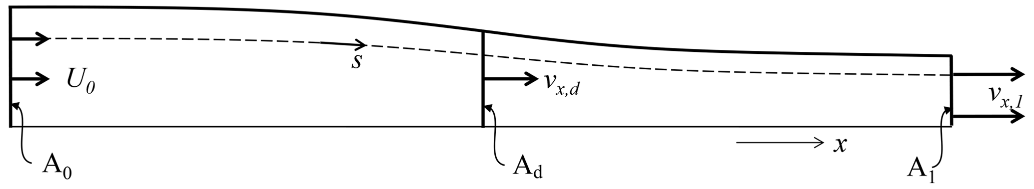
Figure 2The stream tube of a propeller disc from cross sections A0, infinitely far upstream, to A1 in the fully developed wake. Only the upper half of the stream tube is shown.
The pressure and azimuthal velocity are discontinuous across the disc when ϵ→0. For such an infinitely thin disc, integration of Eq. (1) yields
where Δ denotes the jump across the disc and F the applied surface load. A Joukowsky disc has a wake with swirl, induced by a vortex Γ at the axis. The vortex core radius δ is assumed to be infinitely thin. The azimuthal velocity is
The Bernoulli equation reads
When this is integrated across the disc and combined with Eq. (3), the axial component of Eq. (2) becomes
The power converted by an annulus dr of the actuator disc equals the torque Q times rotational speed Ω, giving ΩdQ=2πΩfφr2dr, but also the integrated value of f⋅v with the use of Eq. (1), giving 2πr(v⋅∇)Hdr. Equating both expressions shows that
fφ is expressed by the φ component of the Euler Eq. (1): . Herewith
which gives with Eq. (6)
Consequently, for a Joukowsky disc
In the wind turbine mode ΔH<0, as energy is taken from the flow. With Ω always taken positive, Γ and vφ are negative in the wind turbine mode and positive in the propeller mode. This explains why Γaxis is shown with a negative sign in Fig. 1. Furthermore Eq. (9) shows that for Ω→∞ meanwhile keeping ΔH constant, Γ vanishes and, by Eq. (7), also fφ. The result is the Froude disc without torque and wake swirl.
The power P converted by the disc follows by integration of Eq. (6) on the actuator disc. In dimensionless notation this becomes
With and , Eq. (9) becomes
and similarly Eq. (10) becomes
The thrust T is derived in the same way, based on Eq. (5). Dimensionless, the thrust coefficient is according to the two terms on the right-hand side of (5):
does not contribute directly to the conversion of power, as it does not appear in Eq. (12). It is a conservative contribution to CT, delivering the radial pressure gradient balancing the swirl immediately behind the disc. For finite q and δ→0, . For a non-zero δ combined with high λ and low q, becomes small. For typical wind turbine parameters λ=8, and δ=0.05R with δ representing the blade root cut-out area, .
The power and thrust have the same sign as ΔH or q: positive for propeller discs and negative for wind turbine discs. Consequently, the thrust and power (coefficients) are negative for discs extracting energy from the wake and positive for discs adding energy to the wake.
The velocity in the far wake is characterized by vr=0. Herewith the Bernoulli Eq. (4) becomes in the far wake
The radial derivative is . When this is compared with the condition for radial pressure equilibrium in the fully developed wake, given by substitution of vr=0 in the radial component of Eq. (1),
the result is or, dimensionless, .
3.1 Momentum theory results for propeller and wind turbine discs
The momentum theory presented in van Kuik (2017) is valid when a different sign convention for q is used; as in van Kuik (2017) it was defined instead of Γ∕(2πRU0). This theory lacks an analytical solution. However, a numerical solution of Eq. (19) of van Kuik (2017) is possible. Expressed in λ and q, this is an implicit expression for u1:
where q has changed sign. After solving Eq. (16) for u1, the wake expansion or contraction is given by van Kuik (2017, Eq. 28). The average velocity at the disc is given by van Kuik (2017, Eq. 27), again with a change of sign of q in both equations.

Figure 3 shows for
as well as λ=∞ and . The advance ratio is also given. The part
of the figure with shows
for wind turbine discs and with for propeller discs. For λ=5 the difference with
λ=∞ is smaller than 0.7 %, so the Froude momentum
theory results are practically recovered. Apparently, swirl has little
effect when λ>5. The flow cases a to e are
defined in Table 1, together with two flow parameters:
the dimensionless average velocity at the disc,
, and the dimensionless absolute velocity in
the meridian plane
.
is the same as the velocity along
a streamline vs at the position of the disc, so
.
and will be
examined in the next sections.
Table 1Definition of actuator disc flow cases a to e, the average velocity at the disc and the absolute velocity in the meridian plane .

Several particularities can be observed in Fig. 3:
-
For values of λ<1.4 the minimum attainable , giving , so the flow is blocked. Such a minimum λ exists in the wind turbine as well as propeller flow regime.
-
For wind turbine discs having λ>1.4 the minimum CΔH is −1.0, with shrinking from 0.5 at λ=5 to 0 at λ≈1.4.
-
For propeller discs having a very high J, so the wake expands. This upper boundary of the expanding wake region is the line , giving an undeformed wake. The lower boundary is defined by , giving blocked flow. Both boundaries put a limit to the maximum attainable CT,ΔH. For low J there is no upper limit for CT,ΔH: the wake can be accelerated to any value.
These particularities will be discussed in the next subsections, to start with the propeller disc.
3.2 Propeller discs having an expanding wake
For low rotational speed (low λ, high J), the average axial velocity at the disc deviates from the famous Froude result: . This happens in both flow regimes. Responsible for this is the radial pressure distribution necessary to maintain the swirl. This gives a contribution to the momentum balance, as is explained in van Kuik (2018b, Chapt. 6). The first term in the disc load Eq. (5) gives the contribution of ΔH to the disc load and the second term the swirl related pressure contribution. This contribution is always <0, while the sign of the first term depends on the actuator disc mode: for wind turbine discs <0, for propeller discs >0. Consequently, both terms may cancel for propeller flows, resulting in a zero pressure jump at r=R. With Eqs. (5) and (9) the condition for this particular flow is derived: or
In Fig. 3 this specific flow regime is indicated by the line separating the propeller disc regime with a contracting wake from the propeller disc regime with an expanding wake, with at the separation line. The resulting flow has a wake with a constant radius, so vx=U0, vr=0 throughout the flow. In the wake . The vortex sheet separating the wake from the outer flow consists of axial vorticity across which .
For lower rotational speeds the pressure jump at the edge has become <0, as the swirl-related pressure term in Eq. (5) overrules the ΔH term, thereby generating wake boundary vorticity as for wind turbine disc flows. Although kinetic energy in the wake is lower than outside the wake, the disc load adds potential energy (pressure) to the flow such that the total energy in the wake is higher than upstream. More explanation of this remarkable flow regime is provided in van Kuik (2018b, Sect. 6.3).
3.3 Minimum λ operation with blocked flow
In van Kuik (2018b, Sect. 6.3) the operation at minimum possible λ is analysed. In this flow case as well as u1=0, so the disc acts as a blockage to the flow. In the wake the change of axial momentum is zero, but as the azimuthal velocity is non-zero. Lower values of λ are not possible.
3.4 Flow patterns
Table 1 shows the flow cases, also indicated in Fig. 3, for which the flow field has been calculated numerically with the potential flow method used in van Kuik (2017). An assessment of the accuracy presented in van Kuik (2018b, appendix D). The highest attainable accuracy is applied: calculated values of integrated properties like wake expansion of contraction deviate less than 0.3 % from momentum theory values. The same holds for the local satisfaction of the boundary conditions at the wake boundary , except within a distance 0.02R from the disc edge, where vn may deviate up to 0.02U0 without challenging the condition Ψ=Ψ1 and without affecting integrated flow quantities.
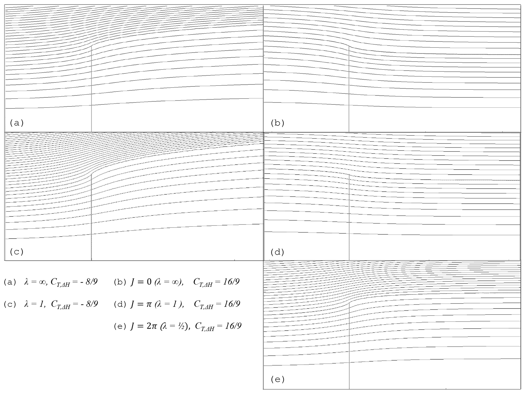
Figure 4The flow patterns of wind turbine discs (a) and (c) and propeller discs (b) and (d) with a contracting wake, (e) with an expanding wake. The streamlines indicate stream tube values increasing with ΔΨ=0.1Ψ1.
In Fig. 4 the streamlines of flow case a
to e are shown, grouped according to their position in
Fig. 3. Flow cases a looks similar to flow
case e, although the latter is a propeller disc flow.
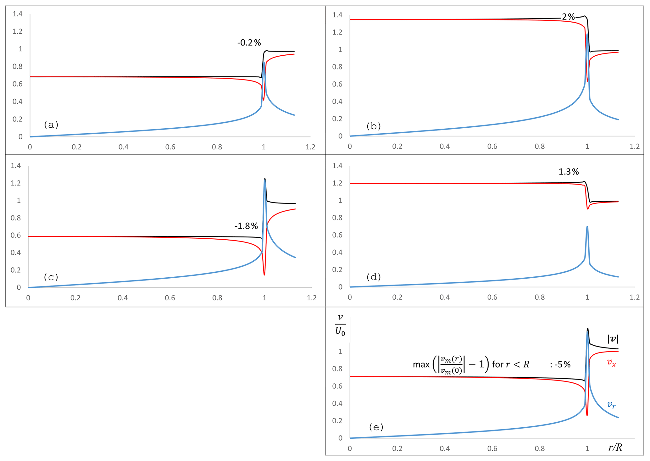
With vs being the velocity in the meridian plane, vs∕U0 at the upstream side of the disc equals . Table 1 gives the numerical values of and for the flow cases considered. The differences between as calculated numerically and as resulting from the momentum theory are 0.2 % or less. The value in the table is the value for r=0. Figure 5 shows the distribution of the axial and radial velocity components and the meridional velocity. Most striking is the distribution of this meridional velocity being practically uniform. The explanation of this is presented in Sect. 5, but first the velocity distributions shown in Fig. 5 are analysed.
4.1 The meridional velocity
Figure 5 shows the amount of non-uniformity in
. This non-uniformity is defined as
, expressed
in percentages, except for flow case a. In all flow cases
except a, increases or decreases
monotonically from r=0 towards r=R. In flow case a,
increases with increasing r, with the
maximum, 0.2 %, reached at after which it
decreases towards the disc edge. At ,
differs −0.1 % from its value at
, so for a the non-uniformity number indicates
. These
numbers for a are within the uncertainty range of the
calculations, so their significance is not clear. The choice for
r=0.97R in the other flow cases is somewhat arbitrary but is
motivated by the argument that the sharp transition at shown
in Fig. 5 is not physically realistic. Viscosity
will smooth this transition depending on the Reynolds number used, as
shown in Sørensen et al. (1998).
4.1.1 Wind turbine flows
As shown in Fig. 5 is
practically uniform in flow case a: the non-uniformity is
−0.2 %. For low λ operation the non-uniformity is
stronger: −1.8 % for flow case c. The
non-uniformity is checked (but not shown in a figure) for several
other flow cases.
-
Disc load , λ=5 instead of ∞: the result differs less than 0.1 %.
-
Discs with λ=∞ but heavier disc loads: the non-uniformity in is −0.7 % for and −0.8 % for .
The optimal operational regime of modern wind turbines is λ>5 with , so the non-uniformity in of flow cases representing this optimal regime is negligible.
4.1.2 Propeller flows
The non-uniformity in is 2 % in
flow case b, J=0. It decreases to 1.3 % in flow
case d, J=π, becomes 0 for J=1.5π when the flow
case without wake deformation is reached according to Eq. (17),
and becomes strongly negative for higher J as shown in flow case
e: −5 % for J=2π. Usually the advance ratio J is lower than 2.5; see for example
McCormick (1994, Fig. 6.12). Figure 3 shows
that in this regime the impact of wake swirl is very limited, so flow
case b is considered representative, with a non-uniformity of
≈2 %.
4.2 The axial velocity
In all flow cases the axial velocity is far from uniform, as was already shown by Sørensen et al. (1998) and Madsen et al. (2010), for example. For Froude wind turbine discs, the cause of this has been addressed in van Kuik and Lignarolo (2016) and for Joukowsky disc flows in van Kuik (2017). In terms of the momentum balance, the source of this non-uniformity is the pressure acting on the sides of a stream annulus used as control volume. When the stream tube boundary is used as the boundary of the control volume, the pressure at this boundary does not give a contribution in the axial direction, but for stream annuli this is not the case. When this pressure is calculated and included in the momentum balance, the prediction of ud per annulus by the momentum theory matches the calculated, non-uniform distribution of the ud. This may serve as the explanation of the non-uniformity of ud but cannot be used as a prediction model as the pressure is not known a priori. For Froude discs the ud distribution has been calculated for , enabling a surface-fit engineering approximation for ; see van Kuik and Lignarolo (2016, Sect. 5.2).
4.3 The radial velocity
The radial velocity receives little attention in actuator disc and rotor publications compared to the axial velocity. Some exceptions are Madsen et al. (2010) presenting an engineering model for the decreased axial velocity close to the disc or rotor edge based on the radial velocity, Micallef et al. (2013) comparing calculated and measured radial velocity near rotor blade tips to assess blade bound chordwise vorticity in order to explain the initially inward motion of the tip vortex, van Kuik et al. (2014, Sect. 4) quantifying this chordwise vorticity and the associated tip load responsible for this inward tip vortex motion, and Sørensen (2015, Sect. 3.2) analysing at the plane of the disc.
Recently Limacher and Wood (2019) found a relation between the axial and radial velocity component in the rotor or disc plane:
where a is the induction and Sd is the plane of the disc or rotor from r=0 to r=∞. Based on Eq. (18), the authors conclude that and a have to be equal close to the disc edge or rotor tip, so
Equations (18) and (19) have been evaluated using the
velocity distributions of Fig. 5. For flow case
a the left-hand side of Eq. (18) indeed approaches 0
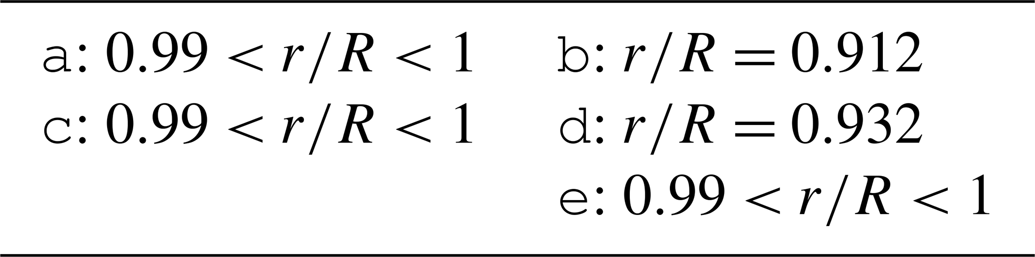
for increasing radius of Sd. Table 2 gives
the radial coordinate where Eq. (19) is satisfied: almost at the
disc edge for the flow cases with an expanding wake a, c and e,
while flow cases b and d with a contracting wake show this
property at a smaller radius. The expanding flows exhibit steep
changes in vx and vr close to r=R. An accurate assessment of
the radial position where Eq. (19) is satisfied is difficult
for which reason a range is indicated.
Table 2The radial position where Eq. (19) is satisfied, for flow cases
a to e.
Equation (19) provides a second relation between
vx,d and vr,d, besides the conclusion of
Sect. 4.1 that is
practically constant for r<R. This allows an engineering estimate of
the wake expansion at the disc for wind turbine flows, when it is
assumed that
and at . As an example
the flow with at r=R is
evaluated, giving . This gives a slope of
the vortex sheet shape of 45∘ at r=R. This is close to flow state
a, where the numerically calculated slope is 46∘, and
which is 3.3 % lower than the
estimate. Further exploration of such an engineering estimate is left
for future work.
The Euler equation of motion (Eq. 1) offers a first-order explanation for the observation that is practically uniform for λ≥1. The radial component of Eq. (1) reads
Equation (3) for vφ combined with Bernoulli's Eq. (4) gives a second equation for :
so the result is , or at the disc
Consequently, the distribution of vs,d is determined by the derivative along the streamline. In case vr has a maximum or minimum at the disc, is uniform.
Qualitative observations regarding the increase or decrease in vr are possible when moving the position along a streamline in the meridian plane. The radial velocity depends only on the vorticity γφ distributed along the wake boundary and the position of observation s*. For a disc with an expanding wake, the following relations hold.
- a.
At the upwind side of the streamline, when moving towards the disc, the distance to γφ decreases, so vr increases, and .
- b.
At the downwind side of the disc the streamline is to be distinguished in two parts: upstream and downstream of s*. The upstream vorticity induces a negative vr,upstream, becoming more negative when s* moves downstream, leading to . The part of the wake downstream of s* remains a semi-infinite wake, so vr,downstream is expected to vary only little for increasing s* (this is to be verified later), leading to . This gives for the total induction in the wake .
Consequently, according to (a) and (b) at the disc and with Eq. (22) so is uniform.
For flow cases with a contracting wake the same reasoning is valid, with an appropriate change of signs, leading to a minimum vr at the disc and a uniform .
However, these qualitative considerations miss the effect that a vortex ring induces a non-zero in the plane of the ring. Figure 6 shows the calculated radial velocity induced by a vortex ring positioned at along the lines . The shape of the plot resembles the induction by a point vortex in a 2−D plane, where dist is the distance to the vortex, and α is the angle of the angular coordinate around the vortex position. As is clear by Fig. 6, this effect is strongest close to the position of the ring, as for . Apart from the distance to the ring, the strength of the ring determines the local value of , as its value is linear in this strength.
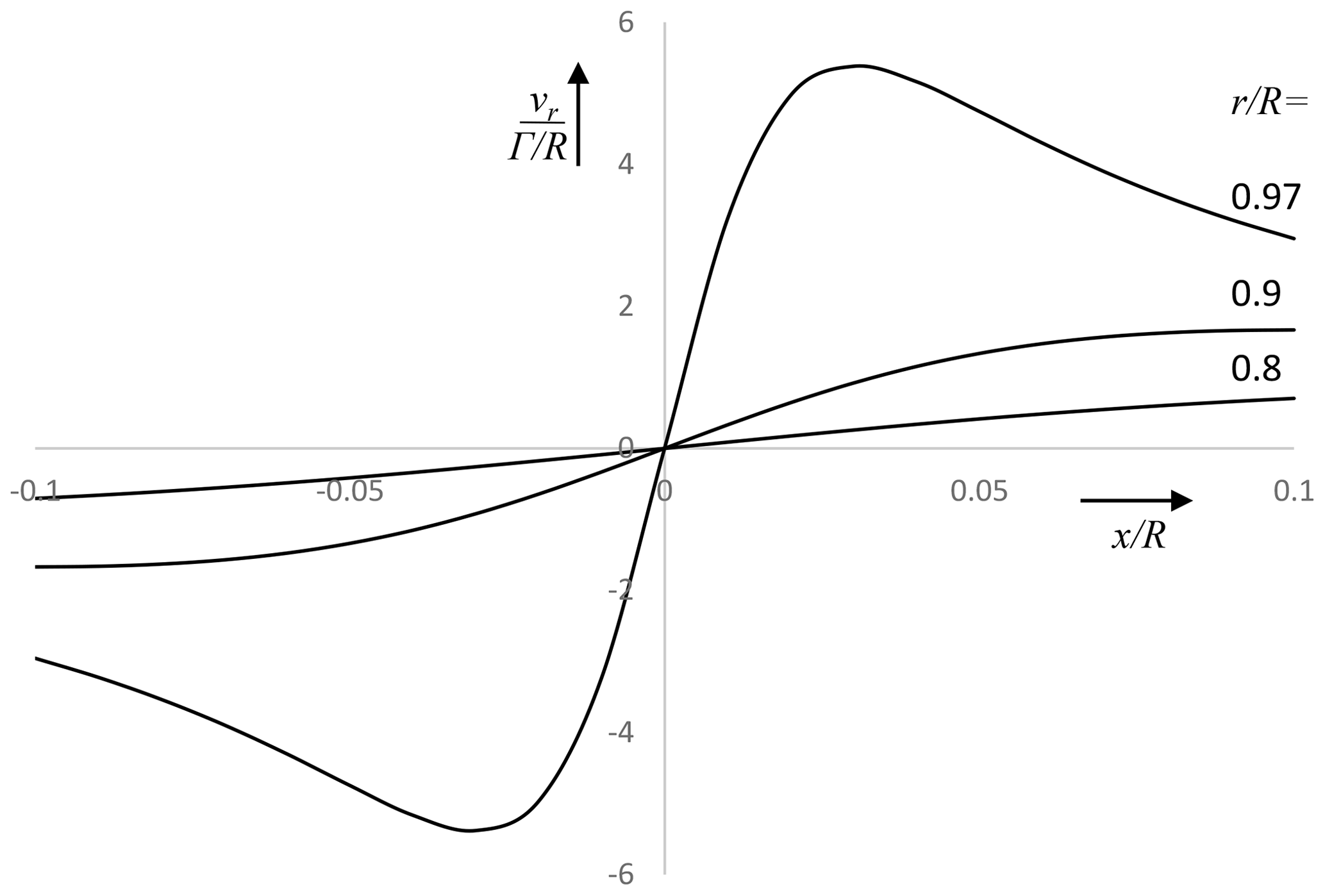
Figure 6The radial velocity induced by a unit vortex ring positioned at R=1, at the lines .
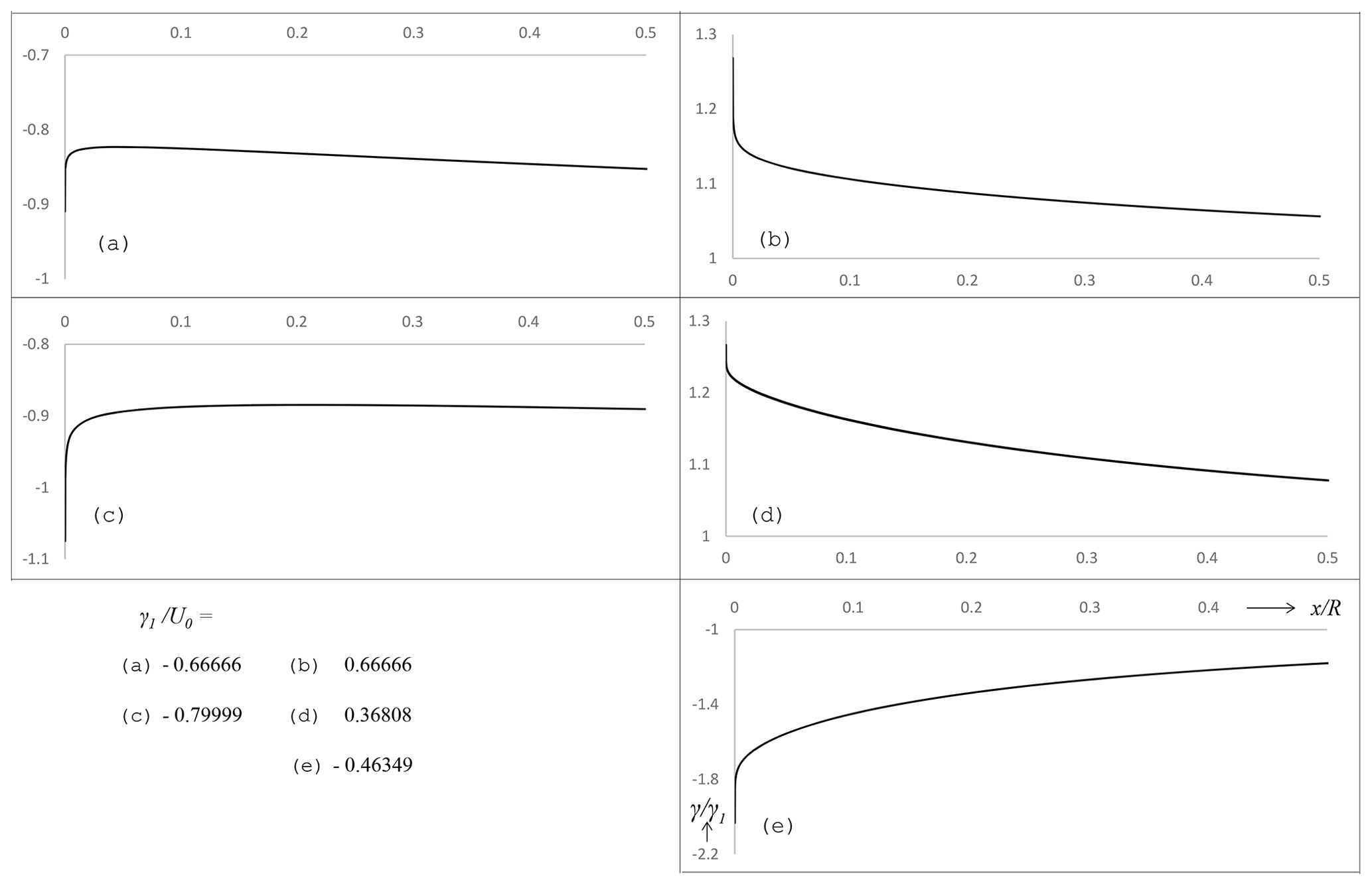
Figure 7The distribution of the vortex sheet strength , for flow cases (a) to (e), defined in Fig. 4. The vertical axes have the same scale, except the axis of (e), which covers a range of γ 4 times larger.
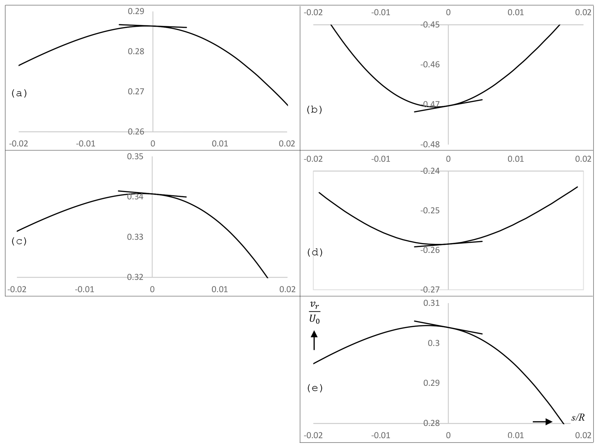
Figure 8Curved lines: the radial velocity along the streamline passing the disc at ; straight lines: the tangent of the distribution vs,d(r)∕U0 at , plotted through the s=0 position at the curved line.
For a vorticity tube things are slightly different, as is easily shown by the example of a tube of constant strength with a semi-finite length. Each elementary vortex ring γdx induces a non-zero in its own plane, but due to symmetry considerations this is annihilated except near and at the beginning of the tube. Also for the vorticity tube surrounding the actuator disc wake, the singular behaviour of is annihilated everywhere by the induction of upstream and downstream vorticity, except at the leading edge of the wake. There the sign of the contribution to at x=0 is opposite to the sign of far upstream, as is clear from the line r=0.97R in Fig. 6.
The argument of non-zero at due to the vortex sheet leading edge has to be added to the arguments (a) plus (b).
- c.
At the induction by the leading edge vorticity at the disc edge adds a contribution to depending on the local vorticity strength and the inverse of the distance to the disc edge. The sign of the contribution is opposite to the sign of upstream of sd.
- d.
According to (a) and (b), the position where is at the disc. With (c) it moves upstream of the disc, for all disc flows. How far it moves upstream depends on the strength of the leading edge vorticity. For discs with an expanding wake, using Eq. (22), , and for discs with a contracting wake . This is in agreement with Fig. 5, showing that vs,d diminishes towards r=R for flow cases
a,cande, while it increases for flow casesbandd.
This qualitative line of arguments (a)–(d) requires a numerical
validation and quantification. The calculated wake vorticity
is shown in
Fig. 7, with γφ,1 being the azimuthal
vorticity in the far wake: . In all
flow cases the distributions have a singularity at the leading
edge. Flow case a has the weakest singularity and flow case
e the strongest. Figure 8 shows the
calculated vr along a streamline passing the disc at
(curved lines) and the tangent at of the distribution
vm(r) (straight line), plotted through the s=0
position at the curved line. As is clear from the graphs, these
straight lines coincide with the tangents to the vr(s)
distribution, confirming Eq. (22). Furthermore, downstream of
the disc vr decreases for flow cases a, c and e and
increases for b and d, thereby confirming the assumption made in
(b).
The absolute value of the slope of the tangents is lowest in flow case
a and highest in e. This is in agreement with the
strength of the leading edge singularity of and the non-uniformity of vm. In
all flow cases vr(s) reaches a maximum or minimum just upstream
of the disc: at for a and −0.00252 for
e, with the values for other flow cases in between these
positions.
With respect to the average velocity at the actuator disc, the following applies.
-
For Joukowsky discs in wind turbine and propeller mode, the average velocity has been found, from λ=0 up to λ→∞ or J→∞ to J=0.
-
For a very high J, propeller disc flows have an expanding wake while still energy is put into the wake. The high angular momentum of the wake flow creates a pressure deficit in the wake, which is supplemented by the pressure added by the disc. This results in a positive energy balance while the wake axial velocity has gone down.
-
Propeller disc flows without wake expansion or contraction are possible for specific values of J, marking the transition from the contracting wake operational mode at low J to the expanding wake mode at high J.
-
In the propeller as well as wind turbine flow regimes the velocity at the disc becomes 0 for very low rotational speed, resulting in a flow with a blocked disc.
With respect to the distribution of the velocity in the meridian plane at the disc position,
-
is practically uniform for wind turbine disc flows with λ>5 (deviation on the order of a few per mille).
-
is almost uniform for wind turbine disc flows with low λ and propeller flows with J≈π (deviation on the order of a few percent).
-
is non-uniform for the propeller disc flow with wake expansion at very high J (deviation on the order of several percent).
-
the differences in uniformity are caused by the different strengths of the leading edge singularity in the wake boundary vorticity strength.
The author declares that there is no conflict of interest.
The author thanks the reviewers David Wood, University of Calgary, Canada, and the anonymous referee. Their comments improved the manuscript significantly. The same holds for the discussion with David Wood and Eric Limacher, Federal University of Pará, Belém, Brazil, about the significance of Eqs. (18) and (19) derived by them in Limacher and Wood (2019).
This paper was edited by Alessandro Bianchini and reviewed by David Wood and one anonymous referee.
Betz, A.: Schraubenpropeller mit geringstem Energieverlust, in: Vier Abhandlungen zur Hydrodynamik und Aerodynamik, Reprint of 4 famous papers by Universitätsverlag Göttingen, Göttingen, 1919. a
Betz, A.: Das Maximum der theoretisch möglichen Ausnützung des Windes durch Windmotoren, Z. gesamt. Turbinenwes., 26, 307–309, 1920. a
Bontempo, R. and Manna, M.: A nonlinear and semi-analytical actuator disk method accounting for general hub shapes. Part 1. Open rotor, J. Fluid Mech., 792, 910–935, https://doi.org/10.1017/jfm.2016.98, 2016. a
Bontempo, R. and Manna, M.: A ring-vortex free-wake model for uniformly loaded propellers. Part II – Solution procedure and analysis of the results, Enrgy. Proced., 148, 368–375, https://doi.org/10.1016/j.egypro.2018.08.007, 2018a. a
Bontempo, R. and Manna, M.: A ring-vortex free-wake model for uniformly loaded propellers. Part I-Model description., Enrgy. Proced., 148, 360–367, https://doi.org/10.1016/j.egypro.2018.08.089, 2018b. a
Bontempo, R. and Manna, M.: On the validity of the axial momentum theory as applied to the uniformly-loaded propeller, 13th European Turbomachinery Conference on Turbomachinery Fluid Dynamics and Thermodynamics, ETC 2019, 7–12 April 2019, Lausanne, Switzerland, 2019. a
Dighe, V. V., Avallone, F., Igra, O., and van Bussel, G.: Multi-element ducts for ducted wind turbines: a numerical study, Wind Energ. Sci., 4, 439–449, https://doi.org/10.5194/wes-4-439-2019, 2019. a
Froude, R. E.: On the part played in propulsion by differences of fluid pressure, 13th Session of the Institution of Naval Architects, 30, 390–405, 1889. a
Goldstein, S.: On the vortex theory of screw propellers, P. Roy. Soc. Lond. A, 123, 440–465, 1929. a
Joukowsky, N. J.: Vortex theory of the screw propeller I, Trudy Avia Raschetno- Ispytatelnogo Byuro (in Russian), also published in: Théorie Tourbillonnaire de l'Hélice Propulsive, Quatrième Mémoire, edited by: Gauthier-Villars et Cie, 1929; 1, 1–47, 16, 1–31, 1912. a
Joukowsky, N. J.: Vortex theory of the screw propeller IV, Trudy Avia Raschetno- Ispytatelnogo Byuro (in Russian), also published in: Théorie Tourbillonnaire de l'Hélice Propulsive, Quatrième Mémoire, edited by: Gauthier-Villars et Cie, 1929; 4, 123–198, 3, 1–97, 1918. a
Joukowsky, N. J.: Joukowsky windmills of the NEJ type, Transactions of the Central Institute for Aero-Hydrodynamics of Moscow, Moscow, 405–430, 1920. a
Lignarolo, L. E. M., Ferreira, C. S., and van Bussel, G. J. W.: Experimental comparison of a wind turbine and of an actuator disc wake, J. Renew. Sustain. Ener., 8, 1–26, https://doi.org/10.1063/1.4941926, 2016. a
Limacher, E. J. and Wood, D. H.: Derivation of an Impulse Equation for Wind Turbine Thrust, Wind Energ. Sci. Discuss., https://doi.org/10.5194/wes-2019-93, in review, 2019. a, b
Madsen, H., Bak, C., Døssing, M., Mikkelsen, R., and Øye, S.: Validation and modification of the Blade Element Momentum theory based on comparisons with actuator disc simulations, Wind Energy, 13, 373–389, https://doi.org/10.1002/we.359, 2010. a, b
McCormick, B. W.: Aerodynamics, Aeronautics and Flight Mechanics, 2nd Edn., Wiley and Sons Inc., New York, USA, 1994. a
Micallef, D., van Bussel, G., Ferreira, C., and Sant, T.: An investigation of radial velocities for a horizontal axis wind turbine in axial and yawed flows, Wind Energy, 16, 529–544, https://doi.org/10.1002/we.1503, 2013. a
Moens, M. and Chatelain, P.: An actuator disk method with tip-loss correction based on local effective upstream velocities, Wind Energy, 18, 766–782, https://doi.org/10.1002/we.2192, 2018. a
Okulov, V. L.: Limit cases for rotor theories with Betz optimization, J. Phys. Conf. Ser., 524, 012129, https://doi.org/10.1088/1742-6596/524/1/012129, 2014. a
Okulov, V. L. and van Kuik, G. A. M.: The Betz – Joukowsky limit: on the contribution to rotor aerodynamics by the British, German and Russian scientific schools, Wind Energy, 15, 335–344, https://doi.org/10.1002/we.464, 2012. a
Okulov, V. L., Sørensen, J. N., and Wood, D. H.: Rotor theories by Professor Joukowsky: Vortex Theories, Prog. Aerosp. Sci., 73, 19–46, https://doi.org/10.1016/j.paerosci.2014.10.002, 2015. a
Ranjbar, M. H., Nasrazadani, S. E., Kia, H. Z., and Gharali, K.: Reaching the betz limit experimentally and numerically, Energy Equip. Syst., 7, 271–278, 2019. a
Sørensen, J. N.: General momentum theory for horizontal axis wind turbines, Springer International Publishing, Heidelberg, https://doi.org/10.1007/978-3-319-22114-4, 2015. a, b
Sørensen, J. N., Shen, W. Z., and Munduate, X.: Analysis of wake states by a full field actuator disc model, Wind Energy, 88, 73–88, https://doi.org/10.1002/(SICI)1099-1824(199812)1:2{<}73::AID-WE12{>}3.0.CO;2-L, 1998. a, b
van Kuik, G. A. M.: Joukowsky actuator disc momentum theory, Wind Energ. Sci., 2, 307–316, https://doi.org/10.5194/wes-2-307-2017, 2017. a, b, c, d, e, f, g, h, i
van Kuik, G. A. M.: Comparison of actuator disc flows representing wind turbines and propellers, J. Phys. Conf. Ser., 1037, 1–10, https://doi.org/10.1088/1742-6596/1037/2/022007, 2018a. a, b, c
van Kuik, G. A. M.: The fluid dynamic basis for actuator disc and rotor theories, open acces edn., IOS Press, Amsterdam, https://doi.org/10.3233/978-1-61499-866-2-i, 2018b. a, b, c, d, e, f
van Kuik, G. A. M.: Background data for the paper: On the velocity at wind turbine and propeller actuator discs, published in Wind Energy Science, 4TU.Centre for Research Data, https://doi.org/10.4121/uuid:c0c94590-2071-470b-bb0e-52f420cbb950, 2020. a
van Kuik, G. A. M. and Lignarolo, L. E. M.: Potential flow solutions for energy extracting actuator disc flows, Wind Energy, 19, 1391–1406, https://doi.org/10.1002/we.1902, 2016. a, b, c
van Kuik, G. A. M., Micallef, D., Herraez, I., van Zuijlen, A. H., and Ragni, D.: The role of conservative forces in rotor aerodynamics, J. Fluid Mech., 750, 284–315, https://doi.org/10.1017/jfm.2014.256, 2014. a
Wood, D.: Maximum wind turbine performance at low tip speed ratio, J. Renew. Sustain. Ener., 7, 053126, https://doi.org/10.1063/1.4934895, 2015. a
Zhong, W., Wang, T. G., and Zhu, W. J.: Evaluation of Tip Loss Corrections to AD/NS Simulations of Wind Turbine Aerodynamic Performance, Appl. Sci., 9, 4919, https://doi.org/10.3390/app9224919, 2019. a