the Creative Commons Attribution 4.0 License.
the Creative Commons Attribution 4.0 License.
 | 02 Feb 2021
An impulse-based derivation of the Kutta–Joukowsky equation for wind turbine thrust
Eric J. Limacher
David H. Wood
Using the concept of impulse in control volume analysis, we derive general expressions for wind turbine thrust in a constant, spatially uniform wind. The absence of pressure in the impulse equations allows for their application in the near wake, where the flow is assumed to be steady in the frame of reference rotating with the blades. The assumption of circumferential uniformity in the near wake – as applies when the number of blades or the tip speed ratio tends to infinity – is needed to reduce these general expressions to the Kutta–Joukowsky (KJ) equation for blade-element thrust. The present derivation improves upon the classical derivation based on the Bernoulli equation by allowing the flow to be rotational in the near wake. The present derivation also yields intermediate expressions for thrust that are valid for a finite number of blades and trailing vortex sheets of finite thickness. For the circumferentially uniform case, our analysis suggests that the magnitudes of the radial velocity and the axial induction factor must be equal somewhere on the plane containing the rotor, and we cite previous studies that show this to occur near the rotor tip across a wide range of thrust coefficients. The derivation reveals one further complication; when deriving the KJ equations using annular control volumes, the existence of vorticity on the lateral control surfaces may cause the local blade loading to differ from the KJ equation, but the magnitude of these deviations is not explored. This complication is not visible to the classical derivation due to its neglect of vorticity.
- Article
(712 KB) - Full-text XML
- BibTeX
- EndNote


Blade-element theory (BET) for wind turbines uses the fundamental assumption that the forces acting on the elements comprising the rotor blades are given by the Kutta–Joukowsky (KJ) theorem. The thrust and torque are balanced by the change in the axial and angular momentum, respectively, of the flow through a control volume (CV) enclosing the rotor; the combination of BET and momentum theory gives rise to blade-element momentum (BEM) theory. BEM is developed in many texts on wind turbine aerodynamics, such as Burton et al. (2011), Wood (2011), Hansen (2015), Schmitz (2019), and Schaffarczyk (2020), so it is unnecessary to repeat it here. Herein, the KJ equation for blade-element thrust will be rederived using impulse theory, and the conditions of its validity are examined.
Although the KJ equations are generally introduced as assumptions in BEM theory, they can be derived using the unsteady Bernoulli equation. This was shown as early as Glauert (1935) and can also be found in Sørensen (2016) and van Kuik (2018). Assuming the trailing wake to be infinitely thin to permit the use of the Bernoulli equation, and representing the rotor's power extraction by a sudden drop in pressure across the rotor plane, sectional thrust can be expressed as follows:
where ρ is fluid density, T is the rotor thrust, x is the radial coordinate, λ is the tip speed ratio, and θ is the azimuthal angle. uθ is the circumferential velocity just behind the rotor. For ease of reference, we have included our own version of the classical Bernoulli-based derivation of Eq. (1) in Appendix A.
In keeping with typical notation in BEM analysis, we define on this near-wake plane, such that positive w corresponds to positive torque. This substitution gives
w is generally interpreted as the circumferential induced velocity at the rotor plane itself, which is assumed in BEM theory to be half that at the plane just behind the rotor. All quantities in Eqs. (1) and (2) have been normalized by freestream velocity and rotor radius.
When the flow is circumferentially uniform, Eq. (1) reduces to the KJ lift theorem, as will be shown later using Stokes' theorem. Here, we merely point out the contradiction in this classical approach. Although the derivation of Eq. (1) required us to assume irrotational flow everywhere in the near wake – save in the vortical wake of vanishing thickness – the assumption of circumferential uniformity will lead to non-zero vorticity on the near-wake plane except in unrealistic special cases (i.e. uθ≡0 or , where k is a constant). Using impulse theory, we offer an improved derivation of the KJ equation for blade-element thrust that avoids this contradiction. The derivation also offers new insights regarding the relative magnitude of radial velocity in the expanding flow upwind and through the rotor.
The remainder of the paper is organized as follows. Since the wind energy research community is likely to be unfamiliar with the concept of “vortical impulse” or “hydrodynamic impulse” – usually referred to simply as “impulse” – we offer a brief introduction in Sect. 2. Section 3 then manipulates the general CV equations furnished by impulse theory to yield simplified integral expressions of wind turbine thrust. The reader interested primarily in the consequences of the present impulse analysis for BEM may skip ahead to Sect. 4. Finally, our conclusions are presented in Sect. 5.
Impulse theory expresses fluid-dynamic forces in terms of the first moment of vorticity (e.g. Wu et al., 2015):
where V is some fluid volume, N is the dimension of the space, x is the position vector, and Ω is the vorticity vector. The use of the word “impulse” may confuse the unfamiliar reader; it is an imprecise yet well-established nomenclature. Lighthill (1986) showed that the first moment of vorticity is equal to the impulse (i.e. the integral of force applied over time) necessary to establish an unbounded vortical flow from rest (the domain is unbounded, but the region of vortical fluid remains bounded). Since then, the term “impulse” has been co-opted to refer specifically to the first moment of vorticity, as recounted in Sect. 2.5 of Limacher (2019), and we will continue to use this terminology here.
The introduction of the concept of impulse removes the pressure and introduces vorticity to the equations of linear momentum conservation. This approach can be traced at least as far back as Thomson (1882), who sought to determine the speed of a vortex ring. In their review, Wu et al. (2015) recount that exact impulse-based expressions for aerodynamic force were derived independently by Burgers (1921), Wu (1981), and Lighthill (1986). Discussions of impulse formulations can also be found in Lamb (1932), Batchelor (1967), and Saffman (1992). They have recently gained popularity for use with planar or volume measurements of fluid velocities from particle image velocimetry and related techniques (e.g. Rival and van Oudheusden, 2017; Limacher et al., 2019, 2020).
Derivation of an impulse-based force formulation begins with the conventional application of the Reynolds transport theorem to the momentum equation and proceeds by manipulating the equations using vector calculus identities. For a full presentation, we recommend the Noca (1997) doctoral thesis, as only a brief overview is given here.
For an inertial CV in an incompressible fluid, the equation for force, F, is given in many fluid mechanics texts and by Noca (1997), Eq. (3.36):
where t is time, and U is the velocity vector. S is the control surface bounding the control volume, V; n is the outward-facing normal on S; I is the unit tensor; P is the pressure; and T is the viscous stress tensor. The n⋅UU term gives the conventional momentum deficit when the equation is used to determine thrust.
The momentum integral – the first integral on the right-hand side of Eq. (4) – can be related to the impulse as given in Eq. (3) by the so-called “impulse-momentum identity” (Noca's Eq. 3.1) at the expense of additional terms. By then removing P using the Navier-Stokes equations and vector identities, Noca obtained his Eqs. (3.55) and (3.56), which we combine as
where N=3 for our analysis, is the kinetic energy per unit mass, and Fv is shorthand for viscous terms evaluated on S. In common with other CV analyses of wind turbines, Fv will be ignored. Equation (5), or its variations in Noca et al. (1997), Wu et al. (2015), and Kang et al. (2017), is the complete, general form of the impulse formulation for fluid-dynamic force for an impermeable body in steady motion. It is as exact as the more familiar Eq. (4), and it serves as the starting point for our analysis.
We consider a wind turbine rotating steadily at a tip speed ratio, λ, defined as the ratio of the circumferential velocity of the blade tips to the wind speed. The latter velocity will be used to normalize all velocities. All lengths are normalized by rotor radius, R. We start by using two variants of a cylindrical CV, both of whose upwind face is well ahead of the blades, and whose radius RCV≫R. This ensures that the streamwise velocity along the surface at RCV is equal to the wind speed. The downstream control surface is either just downstream or just upstream of the rotor plane; these variants are called CV1 and CV2, respectively, as shown in Fig. 1. In both cases, the origin of the cylindrical coordinate system is centred on the downstream face of the CV, as shown on the left of Fig. 1. x is the radial coordinate, z is the axial coordinate, and θ is the azimuthal angular coordinate (and the subscript θ refers to the circumferential direction).
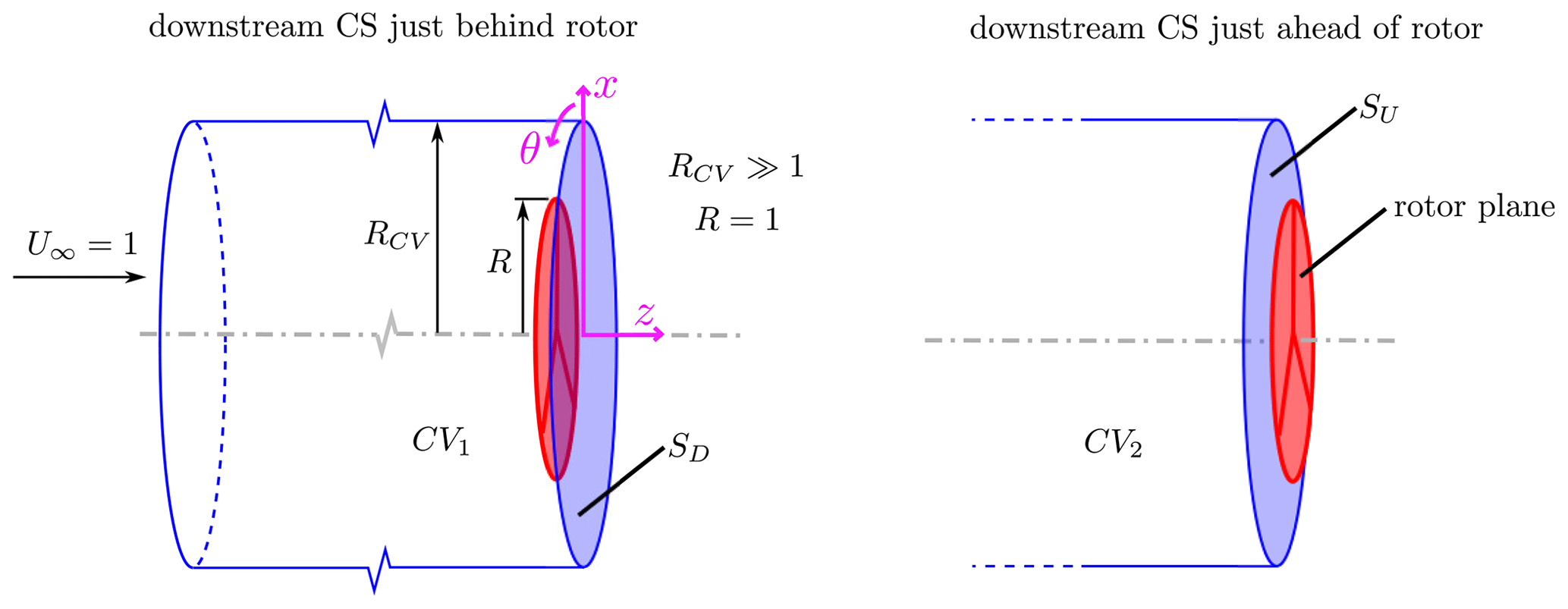
Figure 1Control volumes (CVs) for the present analysis. In both variants, the upstream face is well upstream of the rotor, where the velocity is equal to the freestream, and RCV≫R. The downstream control surface is just downstream and just upstream of the rotor plane in CV1 and CV2, respectively, and the corresponding downstream control surfaces (CSs) are labelled SD and SU.
We now consider the contributions of each term in Eq. (5) to the thrust, defined as
where ez is the unit vector in the z direction. The time derivative of the impulse integral – the first integral in Eq. (5) – does not necessarily vanish identically, but its thrust contribution does. Since the vortical wake is assumed to rotate with the blades, only the direction (but not the magnitude) of the impulse integral can change, and its time derivative reduces to
where Λ is the rotation vector. For steady rotation, Λ=λez, and the thrust contribution of Eq. (7) vanishes since Λ and ez are parallel.
The first two terms in the surface integral on the right-hand side of Eq. (5) can be referred to jointly as the velocity terms. The axial component of the n⋅UU term gives the conventional momentum-deficit term, derived in any textbook on wind turbine aerodynamics:
where CS1 is the external control surface bounding CV1, and SD denotes the downwind face of CV1. is the axial velocity magnitude, and a is the well-known axial induction factor. The term, which we will call the kinetic energy term, contains contributions from all three components of velocity; the thrust contribution from axial velocity is
The right-hand sides of Eqs. (8) and (9) can be summed to give
The kinetic energy term also has a contribution from the radial velocity, v:
and the contribution from the circumferential velocity is
where we have continued the convention to express the circumferential velocity on SD as . The velocities on the lateral cylindrical control surface do not contribute to the kinetic energy term because its normal vector is perpendicular everywhere to ez. Vorticity can be non-zero only on the downstream face of the CV, and the last two terms on the right-hand side of Eq. (5), which we call the vortex terms, simplify to
Because the radial components of velocity and vorticity are parallel to x=xer on SD, where er is the radial unit vector, they lend no thrust contribution through the vortex terms.
So, we have seen that the impulse term's thrust contribution vanishes, the two velocity terms in Eq. (5) are replaced by the sum of Eqs. (10) through (12), and the vortex terms lend the contribution given in Eq. (13). Summing these contributions, the thrust becomes
where all velocities and vorticities are expressed relative to an inertial frame.
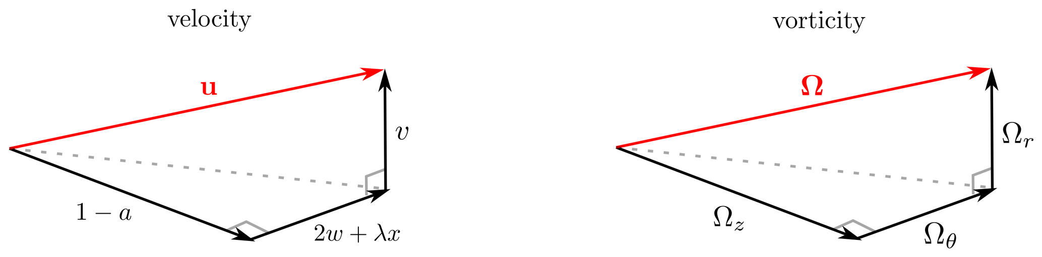
Figure 2Velocity (in the rotating frame of reference) and vorticity vectors in the near wake. If diffusion is neglected and the wake is assumed to be rigid, velocity and vorticity triangles on each orthogonal plane are geometrically similar.
Equation (14) has incorporated the assumptions of steady rotation, a rigid wake, and vanishingly small viscosity. To proceed towards the KJ equation for blade-element thrust, let us assume that the effect of diffusion is negligible on SD, such that Kelvin's circulation theorem applies to individual fluid elements. When combined with the assumption of a rigid wake, it is clear that vortex lines must coincide with streamlines in the rotating frame of reference, or else the structure of the vortical wake would appear to deform in that frame. This alignment of streamlines and vortex lines in three dimensions is illustrated in Fig. 2. On any two-dimensional plane cutting through our three-dimensional volume, the projected velocity and vorticity components generate similar triangles. We are specifically interested in the resulting relationship between axial and circumferential vector components:
This becomes useful if we rewrite the vortex terms as
because the terms in the square brackets of the first integrand cancel by Eq. (15). The remaining term in Eq. (16) can be interpreted as a thrust due to wake rotation. We now manipulate this term to express it in terms of velocity. Substituting dS=x dx dθ into the previous expression, the term becomes
The streamwise vorticity in polar coordinates is
where the negative sign on the w terms is due to our chosen sign convection, whereby positive w corresponds to positive torque. When substituted into Eq. (17), the contribution of vanishes:
The vortex terms thus become
After integrating the first term by parts, and assuming wx3→0 as x→∞, the whole expression becomes
Substituting the expression on the right-hand side into Eq. (14), we arrive at
It is now clear that our derivation is approaching Eq. (2), the precursor to the KJ thrust equation. The next step is to investigate the relationship between v and a, which is done in the next section.
Since a future goal of this research program is unsteady turbine modelling, an alternative derivation of Eq. (22) in the rotating frame of reference is offered in Appendix B.
4.1 Radial velocity
If the downwind face of the CV is moved to be just ahead of the rotor – replacing integrals on SD with integrals on SU in our first use of CV2 shown in Fig. 1 – then T in Eq. (22) becomes zero, since no body is enclosed by the CV. The flow on SU is irrotational, and so the vortex terms in Eq. (14) also vanish, and our CV impulse analysis reduces to
If there are azimuthal variations of v on SU, then there must be corresponding radial variations in uθ to ensure that the axial vorticity remains zero. In the special case of azimuthal uniformity, uθ must vanish on SU so that the circulation around any circle of radius x remains zero (Taylor, 1921). Thus,
for the circumferentially uniform case. van Kuik (2020) directly corroborates Eq. (24), showing it to hold for his model of rotor flow. Since v and a must be continuous across any actuator disk, the equation also holds immediately behind the rotor, but that is the limit to its validity; it cannot hold, for example, in the far wake, where v is everywhere zero but a≠0.
Equation (24) implies that v2=a2 somewhere on SU if both v and a are C0-continuous. In a real flow with finite viscosity, we indeed expect both variables to vary continuously, even if we allow for arbitrarily large (but finite) gradients. At the rotor axis, v=0 by symmetry, but in general a>0 at the axis for a loaded turbine rotor. If a2>v2 over the inner rotor, Eq. (24) requires that v2>a2 over some other part of SU, and the restriction that v and a are continuous then requires v2=a2 for at least one radial location. Previous actuator-disk simulations show that v>a in the flow external to the rotor (x>1), and that v=a occurs near the tip of the actuator disk for a wide range of thrust coefficients, e.g. Figs. 15 and 16 of Madsen et al. (2010), Figs. 3.2 and 3.3 of Sørensen (2016), and Fig. 4 of Branlard and Meyer Forsting (2020). These results indicate a significant radial deflection of the streamlines in the tip region as they pass through a loaded rotor. We are unaware of any study of the effect of this “crossflow” on blade-element forces, but simple expressions for crossflow alterations to airfoil lift and drag are developed by Hodara and Smith (2014).
For a turbine with a finite number of blades, the situation is more complex. The early near-wake measurements of Ebert and Wood (2001) and the recent ones of Eriksen and Krogstad (2017), when converted to co-ordinates rotating with the blades, show large positive and negative values of v(θ) particularly in the tip region. The circumferential average of v or the value at the blades can, therefore, be small while the average of v2 can be significant. The flow in the tip region of a rotor with a finite number of blades can include motion of the tip vortex towards, rather than away from, the axis of rotation (van Kuik et al., 2014).
Assuming that a and v are continuous through the rotor, Eq. (24) applies on SD as well as SU, and Eq. (22) simplifies to
All that remains to recover Eq. (1) is to determine when the blade-element version of Eq. (25) is also valid.
4.2 Blade-element thrust
To determine the blade-element version of Eq. (25), we consider two variants of a cylindrical annular CV: one with the downstream face just upwind of the rotor (V1) and one with it just downwind (V2), as shown in Fig. 3. In the former case, the flow everywhere in the control volume and on the bounding control surface (S1) is irrotational, and since there is no body enclosed by this CV, the thrust is zero and we obtain
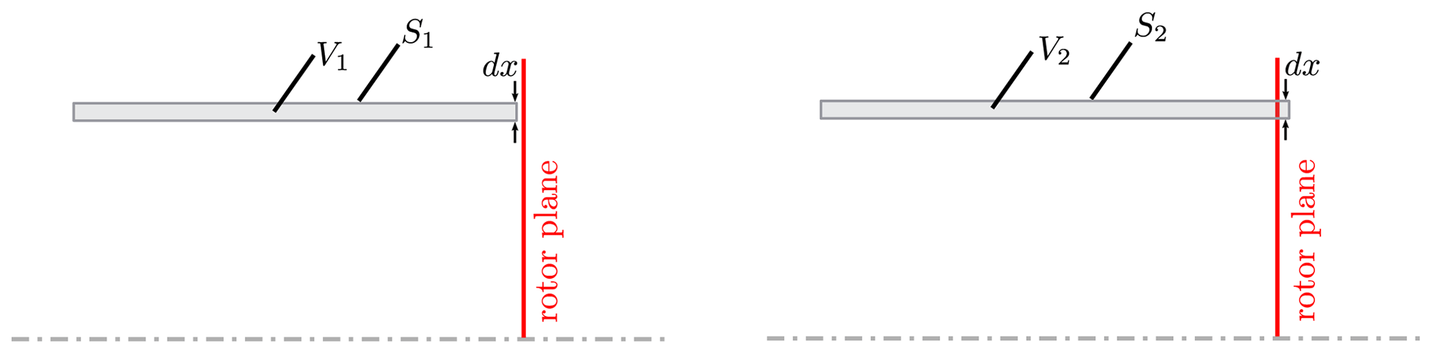
Figure 3Annular CVs used for the blade-element force analysis. The downstream face of width dx is just upstream and just downstream of the rotor for V1 and V2, respectively.
As noted above, the circumferential velocity ahead of the rotor vanishes for a circumferentially uniform flow, in which case only radial and axial velocities contribute to the integral in Eq. (26). Assuming these velocities to be continuous across the rotor, their contribution to the same integrand over S2 also vanishes and we obtain
where is the downstream face of the annular CV, V2. Since the trailing vortices pierce , the vortex terms contribute 2λwx to the integrand of the thrust integral, as in Eq. (22). Vorticity also exists on the lateral boundaries of V2, which we denote and , and the complete thrust contribution of the vortex terms is
The integrals over and do not vanish if the vortex lines and streamlines are coincident (as they did on SD) because diffusion is not negligible in the immediate vicinity of the blades where vorticity is generated. We will nonetheless neglect these contributions without claiming their insignificance, as this simplification facilitates the recovery of the KJ equation. Thereafter combining Eqs. (27) and (28), the expression for blade-element thrust becomes
which is, at last, identical to Eq. (1).
Recall that the classical derivation of Eq. (29) requires the following assumptions: the trailing wake is thin, i.e. it occupies zero volume; it rotates rigidly with the rotor; and the axial and radial velocities are continuous across the disk. We have arrived at Eq. (29) using the latter two of these three assumptions, but we have avoided the thin-wake assumption; the new derivation permits the flow to be rotational in the wake. We have, however, invoked the circumferential uniformity assumption early; this was not required in the classical derivation of Eq. (29) but is necessary to recover the KJ blade-element thrust equation.
4.3 Kutta–Joukowsky equation
When the flow on SD is assumed to be circumferentially uniform, Eq. (29) becomes
The sum of blade circulations, ∑iΓi, at a given radial station is equal to the integral on the right-hand side, as can be derived by Stokes' theorem using Fig. 4. Taking Sa to be a cylindrical surface of radius x intersecting the blades, with Sa bound externally by Ca,
where Ωr is the radial vorticity on Sa, dl is the tangential unit vector along Ca, and only the downstream portion of Ca lends a non-zero contribution to the contour integral (e.g. Taylor, 1921). When all blades are evenly loaded, Eqs. (30) and (31) combine to yield
where N is the number of blades and ΓBE is the bound circulation of the blade element. Equation (32) is the KJ equation for blade-element thrust when w+λx is interpreted as the relative circumferential velocity experienced by the blade element.
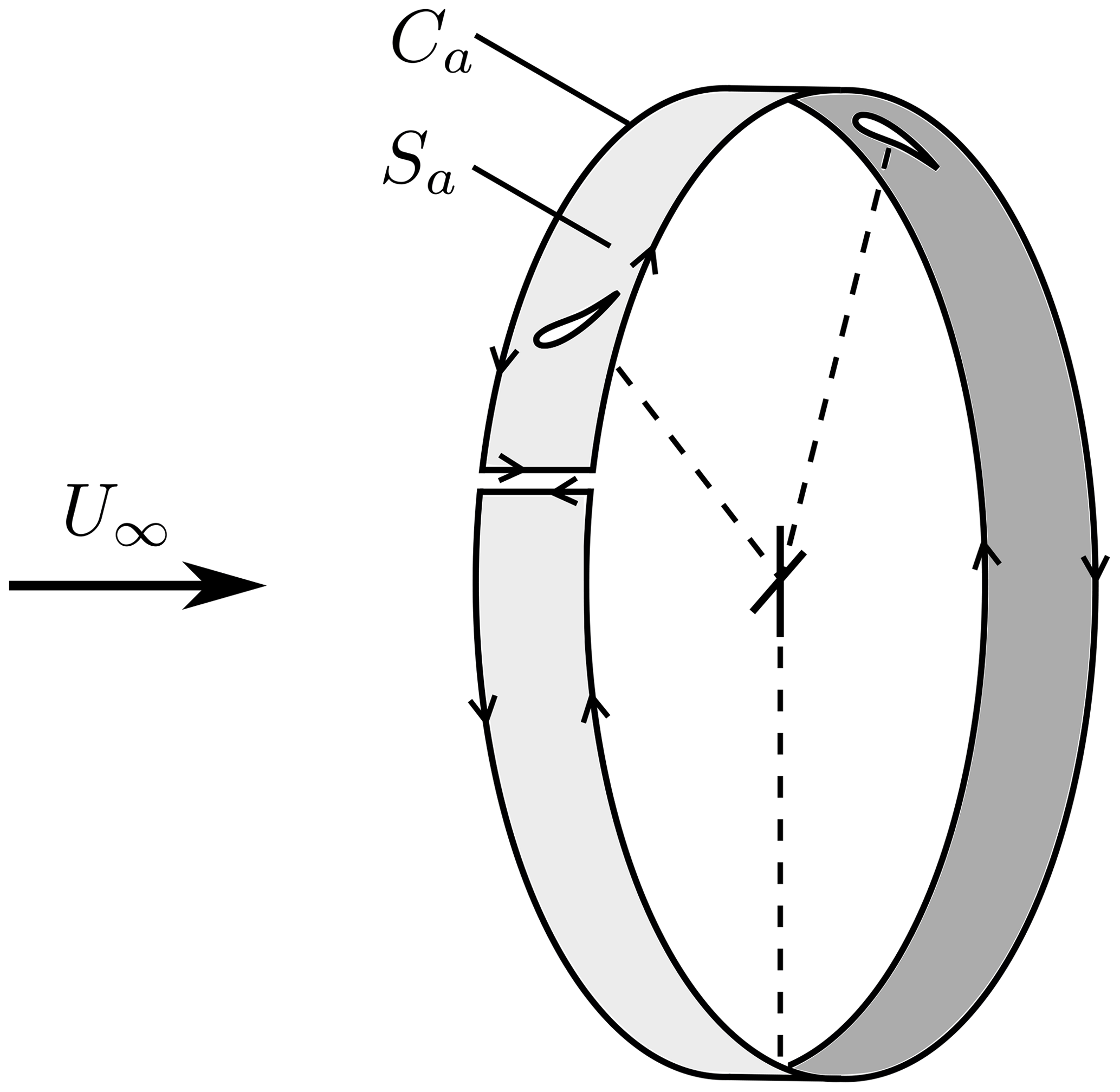
Figure 4The sum of blade circulations at radial station x can be calculated as an area integral of radial vorticity over Sa, or a closed line integral over Ca, where only the downstream circular section of Ca lends a non-zero contribution.
Circumferential uniformity is approached as N→∞, but Eq. (32) is approximately true for finite N when λx≫w. This occurs for the power-producing region of the blades at sufficiently high λ.
In blade-element analysis, the Kutta–Joukowsky equation is usually introduced as an assumption, but this can only be valid as N→∞ and/or λ→∞. This result is directly deducible from Eq. (29) regardless of the method of its derivation.
Recall that we neglected the contribution of the vortex terms on the lateral boundaries of the annular CV to arrive at Eq. (29). Although this assumption led to a result in agreement with the classical approach, this agreement is not sufficient justification. Rather, the classical derivation is simply blind to this effect due to its neglect of vorticity. Future work is needed to investigate the possible significance of the neglected terms.
This paper describes the application of vortical impulse theory to determine the thrust on a steadily rotating wind turbine in a steady, spatially uniform wind. The principal attraction of the impulse approach is the absence of pressure in the force equations, which allows them to be applied anywhere in the flow, including immediately behind the rotor. We assume that the vorticity field is steady when viewed by an observer rotating with the blades, so the vortex lines and streamlines in the near wake are aligned in this frame. Subsequently, we rederive the Kutta–Joukowsky (KJ) equation for blade-element thrust under the special condition of circumferential uniformity in the wake (i.e. as the number of blades or the tip speed ratio tends to infinity). Our derivation improves upon the classical derivation – which is based on the Bernoulli equation – by allowing the wake to be rotational and three-dimensional and is exact for any amount of flow expansion through the rotor. In addition, intermediate steps en route to the KJ equation provide thrust expressions which allow for circumferential non-uniformity and trailing vortex sheets of finite thickness.
The derivation also yields insight into the radial velocity based on Eq. (24). When the wake is circumferentially uniform, the magnitudes of the radial velocity and the axial induction factor must be equal somewhere on the plane containing the rotor, and we cite previous studies that show this to occur near the rotor tip across a wide range of thrust coefficients. Equation (24) was verified in the simulations of van Kuik (2020).
An important avenue for future work is an investigation of the effect of vorticity on the lateral boundaries of the annular control volumes in the immediate proximity of the blades. The blade-element KJ equation was recovered only when these terms were neglected, but the validity of this neglect was not established. This complication is not visible to the classical derivation of the KJ equation due to its neglect of vorticity.
Assume that, at all times, the fluid elements along a streamline passing through the rotor remain irrotational. The trailing vorticity in the wake is assumed to be infinitely thin. The unsteady Bernoulli equation along this streamline is
where C is a constant, and ϕ is the scalar potential. If the wake rotates rigidly with the blades, the unsteady term can be expressed in terms of the circumferential velocity and the rotation rate, λ:
where the negative sign arises because θ is evaluated in the moving frame, i.e. , and the relationship comes directly from the definition of the scalar potential, U=∇ϕ. We now apply Eq. (A1) at locations just up- and downstream of the rotor to solve for the pressure difference across the rotor, Δp. Assuming radial and axial velocities to be continuous across the disk, only the circumferential velocity contributes to Δp:
Substituting , and integrating Δp over the rotor, we recover Eq. (25):
Since the Bernoulli equation along any one streamline is independent of neighbouring streamlines, the blade-element version of this equation should also hold, i.e.
When the polar co-ordinates are attached to the blades rotating at λ, the velocities corresponding to those used in the main text are well upwind, immediately upwind of the rotor, and downwind. Equation (5) requires modification to be expressed in terms of velocities and vorticities evaluated in the rotating frame of reference, U′ and Ω′, respectively. The momentum integral in Eq. (4) is replaced by
In Noca's derivation of Eq. (5) from Eq. (4), the pressure, P, was removed by using the Navier–Stokes equations in the form of his Eq. (3.44):
For a steadily rotating CV, Eq. (B2) becomes
as given, for example, by Eq. (3.2.10) of Batchelor (1967). Clearly, the Coriolis term is the penultimate one and the last is the centrifugal. These have now to be included in Eq. (5). The right side of Eq. (B2) appears explicitly in the second term of Noca's Eq. (3.49) as
which means that, in addition to swapping U for U′ and Ω and Ω′ in Eq. (5), use of a noninertial CV requires the extra terms
The general form of the impulse formulation, Eq. (5), in a steadily rotating frame of reference thus becomes
Fv will be neglected as before, as we expect viscous effects to be no more important for rotating than stationary wakes. It is assumed that the vortical wake appears stationary relative to the rotating blades, such that the time derivative of impulse – the first integral on the right-hand side of Eq. (B6) – vanishes. The Coriolis force can only have radial and circumferential components and the centrifugal force is radial. The radial components cannot contribute to an axial (or indeed to a circumferential) force, and thus the volume integrals of the pseudo-forces at the end of the first line and start of the second line of Eq. (B6) do not contribute to . The axial component of the centrifugal contribution to the pseudo-force surface integral in the second line of Eq. (B6) also vanishes by symmetry, and the remaining Coriolis term can be evaluated using the vector identity . With SD denoting the downwind face of the CV, the net contribution, which lies in the axial direction, is
because the term involving λ2x2 will be equal and opposite at the upwind and downwind faces of the CV.
Thus the reduced form of Eq. (B6) is
Equation (B8) is applied to the CVs shown in Fig. 1, but now rotating at the same λ as the rotor. Rotation does not alter the MD term in Eq. (8) or the contributions to the kinetic energy term from the axial and radial velocities, Eqs. (9) and (11) respectively. The circumferential velocity contribution is altered to
It will again be assumed that w=0 outside the wake.
The vortex terms are better expressed in the inertial frame, , because non-zero values of Ω indicate fluid elements that have experienced viscous shear, whereas the apparent vorticity Ω′ has no such physical interpretation. The vortex terms are equivalently expressed as
For the vortical wake to appear stationary in the rotating frame, Ω must be parallel to U′ everywhere that vorticity is non-zero – that is, vortex lines and streamlines are aligned in the rotating frame – by which and the two integrals in square brackets identically cancel, leaving only
for T. Combining these results leads to
Curiously, three integrals with the integrand 2λwx have arisen from three different origins: the kinetic energy term and the vortex terms each yield the same integral in the positive sense, and the Coriolis term lends an equal and opposite contribution. The choice of which two to cancel is arbitrary, but either choice leads to the final equation:
which is identical to Eq. (22).
No data sets were used in this article.
The work was conceived, executed, and written up equally by both authors.
The authors declare that they have no conflict of interest.
David H. Wood's contribution to this work is part of a research project on wind turbine aerodynamics funded by the NSERC Discovery Program. Eric J. Limacher acknowledges receipt of an NSERC Post-Doctoral Scholarship. The authors thank the anonymous referees and Gijs van Kuik for their valuable comments.
This research has been supported by the NSERC (Discovery Program and PDS).
This paper was edited by Jens Nørkær Sørensen and reviewed by three anonymous referees.
Batchelor, G. K.: An Introduction to Fluid Dynamics, C. U. P., Cambridge, 1967. a, b
Betz, A.: Schraubenpropeller mit geringstem Energieverlust, Dissertation, Göttingen Nachrichten, Göttingen, 1919.
Branlard, E. and Meyer Forsting, A. R.: Assessing the blockage effect of wind turbines and wind farms using an analytical vortex model, Wind Energy, 23, 1–19, 2020. a
Burgers, J.: On the resistance of fluids and vortex motion, Koninklijke Nederlandsche Akademie van Wetenschappen, Proc. B Phys. Sci., 23, 774–782, 1921. a
Burton, T., Jenkins, N., Sharpe, D., and Bossanyi, E.: Wind Energy Handbook. John Wiley & Sons, Chichester, 2011. a
Ebert, P. R. and Wood, D. H.: The near wake of a model horizontal-axis wind turbine: Part 3: properties of the tip and hub vortices, Renew. Energy, 22, 461–472, 2001. a
Eriksen, P. E. and Krogstad, P. Å.: An experimental study of the wake of a model wind turbine using phase-averaging, Int. J. Heat Fluid Flow, 67, 52–62, 2017. a
Glauert, H.: Airplane propellers, in: Aerodynamic theory, Springer, Berlin, Heidelberg, 169–360, 1935. a
Goorjian, P. M.: An invalid Equation in the general momentum theory of the actuator disc, AIAA J., 10, 543–544, 1972.
Hansen, M. O.: Aerodynamics of Wind Turbines, Routledge, London, 2015. a
Hardin, J. C.: The velocity field induced by a helical vortex filament, Phys. Fluids, 25, 1949–1952, 1982.
Hodara, J. and Smith, M. J.: Improvement of crossflow aerodynamic predictions for forward flight at all advance ratios, in: 40th European Rotorcraft Forum, 2–5 September 2014, Southampton, UK, 2014. a
Kang, L., Liu, L., Su, W., and Wu, J.: A minimum-domain impulse theory for unsteady aerodynamic force with discrete wake, Theor. Appl. Mech. Lett., 7, 306–310, 2017. a
Kawada, S.: Induced velocity by helical vortices, J. Aeronaut. Sci., 3, 86–87, 1936.
Lamb, H.: Hydrodynamics, 6th Edn., Dover, New York, 1932. a
Lighthill, J.: An informal introduction to theoretical fluid mechanics, Oxford University Press, New York, 1986. a, b
Limacher, E., Morton, C., and Wood, D.: On the calculation of force from PIV data using the generalized added-mass and circulatory force decomposition, Exp. Fluids, 60, 4, https://doi.org/10.1007/s00348-018-2648-3, 2019. a
Limacher, E., McClure, J., Yarusevych, S., and Morton, C.: Comparison of momentum and impulse formulations for PIV-based force estimation, Meas. Sci. Technol., 31, 054001, https://doi.org/10.1088/1361-6501/ab64ad, 2020. a
Limacher, E. J.: Added Mass and Vortical Impulse: Theory and Experiment, PhD thesis, University of Calgary, Calgary, 2019. a
Madsen, H. A., Bak, C., Døssing, M., Mikkelsen, R., and Øye, S.: Validation and modification of the blade element momentum theory based on comparisons with actuator disc simulations, Wind Energy, 13, 373–389, 2010. a
Noca, F.: On the evaluation of time-dependent fluid-dynamic forces on bluff bodies, PhD thesis, Caltech, available at: https://thesis.library.caltech.edu/3081/ (last access: 28 January 2021), 1997. a, b
Noca, F., Shiels, D., and Jeon, D.: Measuring instantaneous fluid dynamic forces on bodies, using only velocity fields and their derivatives, J. Fluids Struct., 11, 345–350, 1997. a
Okulov, V. L. and Sørensen, J. N. : Refined Betz limit for rotors with a finite number of blades, Wind Energy, 11, 415–426, 2008.
Okulov, V. L., Sørensen, J. N., and Wood, D. H. The rotor theories by Professor Joukowsky: Vortex theories, Prog. Aerosp. Sci., 73, 19–46, 2015.
Rival, D. E. and van Oudheusden, B.: Load-estimation techniques for unsteady incompressible flows, Exp. Fluids, 58, 319–330, 2017. a
Saffman, P. G.: Vortex Dynamics, C. U. P., Cambridge, 1992. a
Schaffarczyk, A. P.: Introduction to Wind Turbine Aerodynamics, Springer Nature, London, 2020. a
Schmitz, S.: Aerodynamics of Wind Turbines – A Physical Basis for Analysis and Design, Wiley, New York, 2019. a
Sørensen, J. N.: General Momentum Theory for Horizontal Axis Wind Turbines, Springer International Publishing, Heidelberg, https://doi.org/10.1007/978-3-319-22114-4, 2016. a, b
Sørensen, J. N. and Mikkelsen, R.: A critical view on the momentum theory, in: Torque 2012 conference, 9–11 October 2012, Oldenburg, 2012.
Taylor, G. I.: The “Rotational Inflow Factor” in Propeller Theory, ARC R & M no. 765 – Reprinted in G. Batchelor (ed): The Scientific Papers of G. I. Taylor, 3, C. U. P., Cambridge, 59–65, 1921. a, b
Thomson, J. J.: A Treatise on the Motion of Vortex Rings, Macmillan, Cambridge, 1833. a
van Kuik, G. A. M.: The fluid dynamic basis for actuator disc and rotor theories, IOS Press, Amsterdam, 2018. a
van Kuik, G. A. M.: On the velocity at wind turbine and propeller actuator discs, Wind Energ. Sci., 5, 855–865, https://doi.org/10.5194/wes-5-855-2020, 2020. a, b
van Kuik, G. A. M., Micallef, D., Herraez, I., Van Zuijlen, A. H., and Ragni, D.: The role of conservative forces in rotor aerodynamics, J. Fluid Mech., 750, 284–315, 2014. a
Wood, D. H.: Small wind turbines: analysis, design, and application, Springer, London, 2011. a
Wood, D. H. and Okulov, V. L. : Nonlinear blade element-momentum analysis of Betz-Goldstein rotors, Renew. Energy, 107, 542–549, 2017.
Wu, J. C.: Theory for aerodynamic force and moment in viscous flows, AIAA J., 19, 432–441, 1981. a
Wu, J. Z., Ma, H. Y., and Zhou, M. D.: Vortical Flows, Springer, Berlin, Heidelberg, 2015. a, b, c
- Abstract
- Introduction
- Background on impulse theory
- The impulse equation for rotor thrust
- Implications for blade-element momentum theory
- Summary and conclusions
- Appendix A: Derivation of blade-element thrust from the unsteady Bernoulli equation
- Appendix B: The impulse equation for thrust in steady rotating coordinates
- Data availability
- Author contributions
- Competing interests
- Acknowledgements
- Financial support
- Review statement
- References