the Creative Commons Attribution 4.0 License.
the Creative Commons Attribution 4.0 License.
 | 17 May 2022
Seismic soil–structure interaction analysis of wind turbine support structures using augmented complex mode superposition response spectrum method
Masaru Kitahara
Takeshi Ishihara
In this study, the seismic soil–structure interaction (SSI) of wind turbine support structures is investigated based on the complex mode superposition approach. For accurate and efficient estimation of seismic loadings on wind turbine support structures, an augmented complex mode superposition response spectrum method (RSM) is developed, where the maximum shear force and bending moment of the non-classically damped system are analytically derived. An empirical formula of the modal damping ratios with a threshold value for the allowable damping ratio is also proposed to improve the prediction accuracy of the shear force acting on the footing. Furthermore, additional loadings to consider the contribution of the mass moment of inertia of rotor and nacelle assembly and P−Δ effect to the bending moment on the tower are analytically derived. The proposed formulae are first demonstrated upon a 2 MW wind turbine supported by two different types of foundations. A parametric study is then carried out by changing the tower geometries and soil conditions to propose the threshold value for the allowable damping ratio.
- Article
(857 KB) - Full-text XML
- BibTeX
- EndNote


Over the past few decades, growing demand for wind energy has increased the construction of wind turbines in earthquake-prone regions, e.g. Japan, and damages on wind turbine support structures caused by huge earthquakes have been reported. A piled foundation was damaged at Kashima wind farm during the Tohoku earthquake in 2011 off the Pacific coast (Ashford et al., 2011), and a wind turbine tower was buckled at Kugino wind farm during the 2016 Kumamoto earthquake (Harukigaoka Wind Power Inc., 2016). To ensure the structural integrity of wind turbine support structures against such huge earthquakes, development of an accurate and efficient method for estimating seismic loadings acting on wind turbine support structures is necessary.
The response spectrum method (RSM) (Der Kiureghian, 1981; Chopra, 2011) has been widely incorporated into the codes for seismic design of various types of structures, including bridges, high-rise buildings, and nuclear power plants, due to its simplicity and efficiency (see, e.g. Eurocode 8, 2004; The building centre of Japan, 2016; American Society of Civil Engineers, 2006). However, it has been recognized that these codes are generally not applicable for designing wind turbine support structures owing to their unique structural characteristics. First, wind turbines have significantly low structural damping (e.g. about 0.2 % for mega-watt (MW) class wind turbines) compared with the other types of structures. Response spectra of the structure with a low structural damping demonstrate large fluctuations, while damping correction factors in the above codes cannot accurately capture such uncertainty in the response spectra. To cope with this issue, Ishihara et al. (2011) have proposed a new damping correction factor for wind turbine support structures, in which the uncertainty in the response spectra is taken into account by employing a quantile value. More recently, Kitahara and Ishihara (2020) have extended the applicability of the damping correction factor for MW class wind turbine support structures.
Second, the mass ratio between the super- and sub-structures of wind turbines is significantly different, and the footing mass can reach about 6 times total masses of the tower, rotor, and nacelle, particularly in earthquake-prone regions (Ishihara, 2010). Therefore, seismic responses of wind turbine support structures are severely affected by soil–structure interaction (SSI) (Wolf, 1989; Zhao et al., 2019). An efficient approach to account for the effect of SSI in seismic analysis is to describe the soil–structure system as a seismic SSI model, where the coupling between the soil and foundation is substituted with a set of springs and dashpots at the soil–foundation interface. This approach has been widely utilized for seismic analysis of wind turbine support structures (Bazeos et al., 2002; Butt and Ishihara, 2012; Stamatopoulos, 2013). However, by introducing the dashpots, the seismic SSI model will be a non-classically damped system, and thus classical modal damping models, such as the Rayleigh damping model, cannot accurately represent its modal damping properties. Although the modal damping ratios of non-classically damped systems can be computed by solving a complex eigenvalue problem, the modal damping ratios of complex eigenmodes cannot be directly used in conventional RSM, where real eigenmodes are employed, because complex eigenmodes do not generally coincide with real eigenmodes. In order to overcome this obstacle, Kitahara and Ishihara (2020) have proposed a modal decomposition method to identify equivalent modal damping ratios of real eigenmodes from the modal damping ratios of complex eigenmodes and have estimated seismic loadings acting on wind turbine support structures by the framework of conventional RSM.
On the other hand, studies have also been conducted on the superposition of complex eigenmodes for seismic analysis of non-classically damped systems (Zhou et al., 2004; De Domenico and Ricciardi, 2019). The complex mode superposition is, in general, formulated based on velocity and displacement responses of each mode, and hence the velocity and displacement response spectra are necessary to employ it for RSM. Recently, Gao et al. (2020) developed an efficient complex mode superposition RSM, where the velocity and displacement response spectra are approximately estimated from the acceleration response spectrum by the so-called pseudo spectrum transformation. This method has been demonstrated upon three- and six-storey shear structures to be capable of accurately and efficiently estimating peak values of story drifts based on a design acceleration response spectrum. However, in these structures, highly damped modes are not dominant on the seismic responses; thus, the estimation accuracy of the seismic responses of highly damped systems by this method has not been clarified. Comparatively, the most dominant mode on the shear force acting on substructures of wind turbines such as footings can demonstrate a very large damping ratio in the case where soft soil profiles are assumed. Therefore, it is still necessary to further investigate the applicability of the complex mode superposition RSM for seismic analysis of wind turbine support structures.
The aim of the present work is consequently to develop an augmented complex mode superposition RSM for accurate and efficient estimates of seismic loadings acting on wind turbine support structures. Section 2 describes the seismic SSI model for wind turbine support structures and input acceleration response spectrum. In Sect. 3, the maximum shear force and bending moment of the non-classically damped system are analytically derived by the complex mode superposition, and an empirical formula of modal damping ratios with a threshold value for the allowable damping ratio is proposed to suppress underestimation of the shear force on footings. Furthermore, additional loadings caused by the mass moment of inertia of the rotor and nacelle assembly (RNA) and the P−Δ effect are also derived using the complex mode superposition. The proposed formulae are validated by the comparison with time history analyses (THAs) considering the uncertainty of the input ground motions in Sect. 4. The threshold value of the allowable damping ratio is proposed based on a parametric study that varies the damping ratio of the most dominant mode on the shear force acting on the footing from 6 % to 58 % by changing tower geometries and soil conditions. The conclusions are summarized in Sect. 5.
In this study, wind turbine support structures subjected to a horizontal ground motion are investigated, aiming at estimating seismic loadings on towers and footings. First, a sway-rocking (SR) model for wind turbine support structures is constructed in Sect. 2.1, where the effect of SSI is considered using a pair of springs and dashpots in the sway and rocking directions, respectively. The methods to estimate the stiffness constants and damping coefficients are briefly summarized for two types of the foundation employed, i.e. the gravity and piled foundations. An input acceleration response spectrum is then defined in Sect. 2.2, accounting for the effects of soil amplification and damping correlation.
2.1 Seismic SSI model for wind turbine support structures
Figure 1 shows the seismic SSI model for wind turbine support structures represented as a SR model, where x and z denote the horizontal and vertical coordinates, respectively, and the th node represents each degree of freedom (DOF) of the steel tower and footing. The number of DOFs is set as n=27, which fulfils the requirement in the guidelines for design of wind turbine support structures and foundations by the Japan Society of Civil Engineers (Ishihara, 2010). The tower and footing are modelled by lumped masses at each node and Euler–Bernoulli beam elements. Furthermore, in this model, RNA is simplified as a lumped mass at the hub height (k=n) and is connected to the tower using a rigid beam. It has been validated that this simplification does not affect the prediction accuracy of seismic loadings acting on the tower and footing, excluding the underestimation of the bending moment at the hub height due to no consideration of the mass moment of inertial RNA (Kitahara and Ishihara, 2020). In this study, this underestimation is compensated for by an additional loading due to the angular acceleration at the hub height, which will be further investigated in Sect. 3.2.
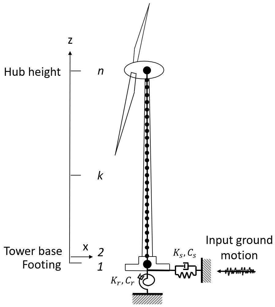
Two types of the foundation, i.e. the gravity and piled foundations, are considered. The gravity foundation is typically employed in the case where stiff soil profiles are considered, while the piled foundations are necessary to be installed in the case where soft soil profiles are considered. Regardless of the foundation type, the soil–foundation system is substituted with a pair of springs and dashpots in the sway and rocking directions, respectively, connected to the footing bottom. It should be noted that, for simplification, the frequency dependencies of the springs and dashpots, cross-coupling between the sway and rocking springs, and mass moment of inertia of the piles are all neglected in this model. These simplifications are reasonable, since the slightly embedded footing with a small embedment ratio, which is defined as the ratio of the footing depth to width, is employed in this study.
The dynamic finite element equation of the seismic SSI model with respect to relative motions can be written as
where MT is the mass matric of the tower; MF and JF mean the mass and mass moment of inertia of the footing; CTT and CTF denote the damping matrices of the tower and coupling between the tower and footing; CFF, Cs, and Cr indicate the damping coefficients of the footing and dashpots in the sway and rocking directions; KTT and KFT denote the stiffness matrices of the tower and coupling between the tower and footing; KFF, Ks, and Kr mean the stiffness constants of the footing and springs in the sway and rocking directions; is a column vector of the relative displacement of the tower; and θF indicate column vectors of the relative displacement and rotational angle of the footing; h is a column vector of the height at each DOF of the tower relative to the footing; I means a unit column vector; and is the input ground motions at the footing bottom.
In this study, a Rayleigh damping model is used based on the first and second natural frequencies and modal damping ratios to obtain the damping matrix in Eq. (1), except for the contribution of the dashpots in the sway and rocking directions. The first and second modal damping ratios are assumed to correspond to the structural damping of steel towers, since these two modes correspond to the sway motion of the tower. The structural damping of steel towers can vary depending on their size. An empirical formula to estimate the structural damping from the characteristic period of the fixed foundation model of wind turbine support structures has been proposed as (Oh and Ishihara, 2018)
where Ts denotes the characteristic period, and 0.2 % indicates the maximum value of the structural damping of unlined welded steel stacks as shown in ISO 4354 (2009).
For the gravity foundation, the parameters of the soil–foundation system in Eq. (1), Ks, Kr, Cs, and Cr, can be obtained using the cone model as detailed by the Architectural Institute of Japan (2006). For the piled foundation, on the other hand, Ks and Kr can be calculated by Francis and Randolph models, respectively (Francis, 1964; Randolph, 1981), while Cs and Cr can be estimated using the Gazetas model (Gazetas and Dobry, 1984). The detailed derivation of these parameters is provided by Ishihara and Wang (2019).
2.2 Input acceleration response spectrum
The design acceleration response spectrum is typically defined at the bedrock condition. The input ground motions at the footing bottom can be obtained by generating simulated waves from it accounting for a given phase property and amplifying them by the one-dimensional site transfer function. Meanwhile, RSM uses the input acceleration response spectrum defined at the footing bottom. Several formulae are proposed such as Eurocode 8 (2004), The building centre of Japan (2016), and American Society of Civil Engineers (2006), and the following equation that is defined in The building centre of Japan (2016) is employed in this study:
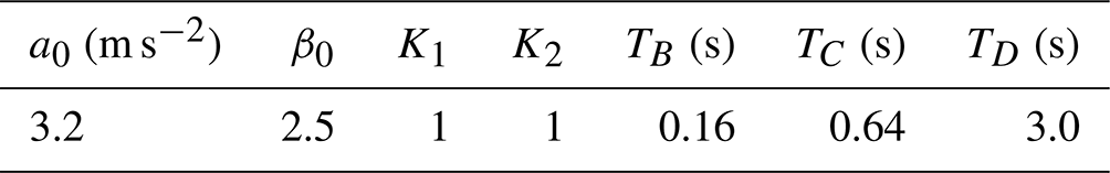
where T and ζ mean the characteristic period and damping ratio; a0 is the peak ground acceleration at the bedrock condition; Gs is the soil amplification factor; Fζ is the damping correction factor; β0 is the acceleration response magnification ratio for the region where the acceleration response becomes constant; and TB, TC, TD, K1, and K2 are coefficients describing the shape of the response spectrum. The parameters used in this study are listed in Table 1. The peak ground acceleration a0 is chosen such that its return period is 475 years as recommended in IEC61400-1 (2019). In addition, the soil amplification factor Gs is obtained using the response-spectrum-based method proposed by Okano and Sako (2013).
Table 1Parameters of the input acceleration response spectrum.
The damping correction factor Fζ is the key component in the acceleration response spectrum, because it quantifies the uncertainty in the spectra of the input ground motions caused by the low structural damping of wind turbines. In this study, the following equation is employed (Kitahara and Ishihara, 2020):
where γ denotes the quantile value. By changing the quantile value γ, the resultant input acceleration response spectrum can consider different reliability levels of the input ground motions, e.g. the mean or maximum spectra. One can refer to Kitahara and Ishihara (2020) for more details of the damping correlation factor.
A state-of-the-art RSM based on the complex mode superposition, called complex mode superposition RSM (Gao et al., 2020), is employed in this study. Section 3.1 gives a brief review of the complex mode superposition RSM, and then it is extended in Sect. 3.2 for estimating seismic loadings on wind turbine support structures. The maximum shear force and bending moment of the multi-DOF system are analytically derived to estimate these on the tower and footing. An empirical formula of the modal damping ratios is then proposed to suppress underestimation of the shear force of the footing. Finally, additional loadings due to the mass moment of inertia of RNA and the P−Δ effect are also analytically derived.
3.1 Complex mode superposition RSM in Gao et al. (2020)
In the complex mode superposition RSM, Eq. (1) is converted into a first-order matrix equation as (Foss, 1958)
with
and The complex eigenvalue problem of this first-order matrix equation is written as
where λj means the jth complex eigenvalue, and , with the jth complex mode shape ϕj, means the jth complex eigenvector. Note that the eigenvalue λj and eigenvector Φj are in complex-conjugate pairs with and , respectively. Based on the jth complex eigenvalue λj, the jth natural frequency and modal damping ratio can be obtained as
Conversely, the first-order matrix equation in Eq. (5) can be also decoupled into the n single-DOF equations as
where qj indicates the displacement response of the single-DOF system. By the superposition of the solutions of Eq. (8), the relative displacement in Eq. (5) can be written as
with
where
The maximum relative displacements can be obtained using the complex complete quadratic combination rule as (Gao et al., 2020)
where N(≤n) denotes the highest mode considered in the calculation; Sdj and Svj are the relative displacement and relative velocity response spectra of the jth mode; and , , and refer to the displacement–displacement, velocity–displacement, and velocity–velocity correlation coefficients between the jth and lth modes, respectively. By utilizing the so-called pseudo spectrum transformation, the displacement and velocity response spectra can be approximately obtained based on the given acceleration response spectrum as (Gao et al., 2020)
where Sa(Tj,ζj) indicates the acceleration response spectrum in Eq. (3) with the jth natural period and modal damping ratio. Moreover, the correlation coefficients , , and are expressed as
where refers to the natural frequency ratio of the jth to lth modes.
3.2 Augmentations for seismic loadings estimate on wind turbine support structures
Whereas the complex mode superposition RSM derives the maximum relative displacement in Eq. (10), the maximum shear force and bending moment are defined based on the maximum acceleration. Hence, they are newly derived herein as
with
and
where Ajk and Bjk indicate the kth component of Aj and Bj, respectively, and mk and zk are the mass and height of the kth node, respectively. Equation (15) will demonstrate how to estimate seismic loadings on the tower and footing of a 2 MW wind turbine in the next section.
Gao et al. (2020) have demonstrated the complex mode superposition RSM upon three- and six-storey shear structures, where highly damped and over-damped modes arise at the fundamental frequencies. However, these modes are not dominant on the seismic responses, i.e. peak values of story drifts; hence, the estimation accuracy of the seismic responses of highly damped systems by this method has not been clarified. In particular, this method might underestimate the seismic responses of highly damped and over-damped modes, since the velocity–displacement correlation for a large damping ratio cannot be accurately evaluated based on the correlation coefficient in Eq. (13). On the other hand, one of the fundamental modes of wind turbine support structures corresponds to the sway motion of the footing, and this mode can show an excessively large damping ratio in the case where soft soil profiles are considered, due to the soil radiational damping. As will be detailed in the next section, this mode is not dominant on seismic loadings on the tower and footing, except for the shear force on the footing. However, the shear force on the footing is the key component for designing the piled foundations, and hence its underestimation could result in unsafe piled foundations. To prevent the underestimation of the shear force on the footing, an empirical formula of the modal damping ratios is proposed in this study as
where ζthr denotes a threshold value of the allowable modal damping ratio. This formula substitutes a given threshold value for the excessive values of the modal damping ratios. It is found that 0.1 is a reasonable choice of the threshold value ζthr based on the parametric study varying the modal damping ratio of the most dominant mode on the shear force on the footing from 6 % to 58 %, which will be detailed in Sect. 4.2.
Moreover, to compensate for the underestimation of the bending moment at the hub height because of no consideration of the mass moment of inertial RNA, an additional loading by the angular acceleration at the hub height is proposed as
where denotes the additional loading the kth node, Iy is the mass moment of inertial RNA, indicates the angular acceleration at the hub height, indicates the maximum acceleration of the first mode at the nth node, and C is the correction factor. The maximum acceleration of the first mode at the nth node can be estimated as
Besides, the P−Δ effect is also proposed to be considered as an additional loading using the framework of the complex mode superposition RSM as
where g means the gravitational acceleration, and is the maximum relative displacement at the kth node obtained by Eq. (10). These additional loadings will be demonstrated in the next section by a comparison with the mean profiles of the maximum bending moment on the tower and footing, estimated by THA of the full finite element (FE) models of wind turbine support structures including the detailed configuration of the rotor and nacelle.
The proposed augmented complex mode superposition SRM is first demonstrated on a typical 2 MW wind turbine supported by different types of foundations in Sect. 4.1. The gravity foundation is used for a typical stiff soil profile, while the piled foundation is utilized for a typical soft soil profile. In Sect. 4.2, to demonstrate the proposed threshold value, ζthr=0.1, in Eq. (16), a parametric study where the modal damping ratio of the most dominant mode on the shear force on the footing is varied from 6 % to 58 % is then conducted by changing tower geometries and soil conditions.
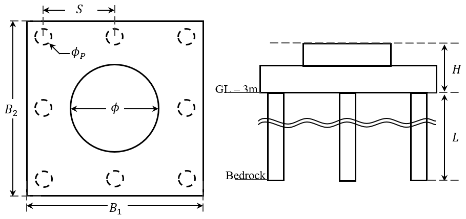
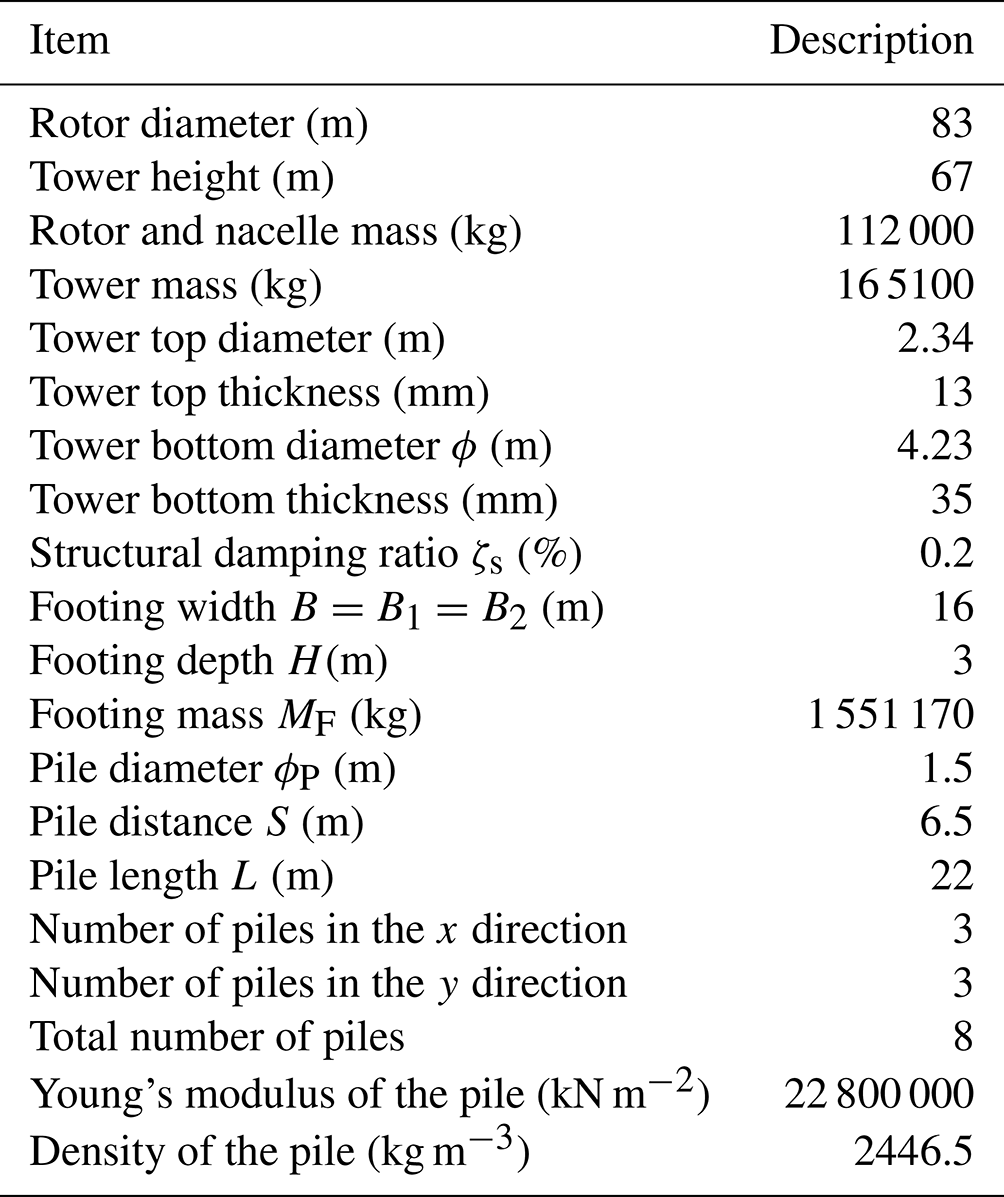
Table 2The outline of the 2 MW wind turbine and its support structures.
4.1 Seismic loadings on a 2 MW wind turbine support structure
Table 2 details the outline of the 2 MW wind turbine and its support structures. The structural damping ratio is estimated as ζs=0.2 % by Eq. (2). The footing mass is about 6 times the total mass of the tower, rotor, and nacelle. The embedded ratio of the footing is assumed as 0.2. On the other hand, Fig. 2 illustrates the shape of the footing and piles. In totally eight piles are embedded and extended to the depth of the bedrock condition. The water depth is assumed to be under the pile bottom.
As the soil profiles, typical stiff and soft soil profiles, namely Soil types I and II, shown in Architectural Institute of Japan (2006) are considered in this study. Table 3 details the description of the one-dimensional layered soil models for these two soil profiles. The gravity foundation is utilized for Soil type I, while the piled foundation is used for Soil type II. In addition, Table 4 summarizes the stiffness constants and damping coefficients of the soil–foundation system, i.e. the pair of springs and dashpots in the sway and rocking directions, for both soil profiles.
Table 3The description of one-dimensional layered soil models.
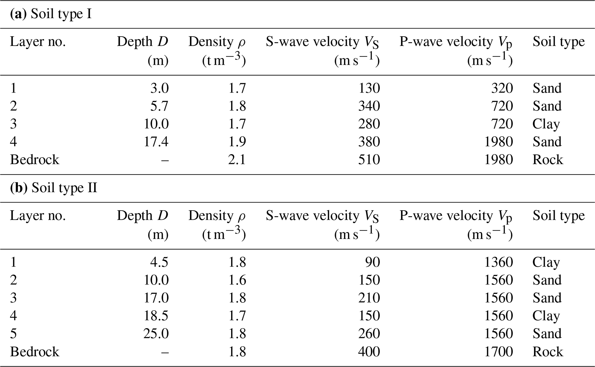
Table 4Stiffness constants and damping coefficients for the soil–foundation system.
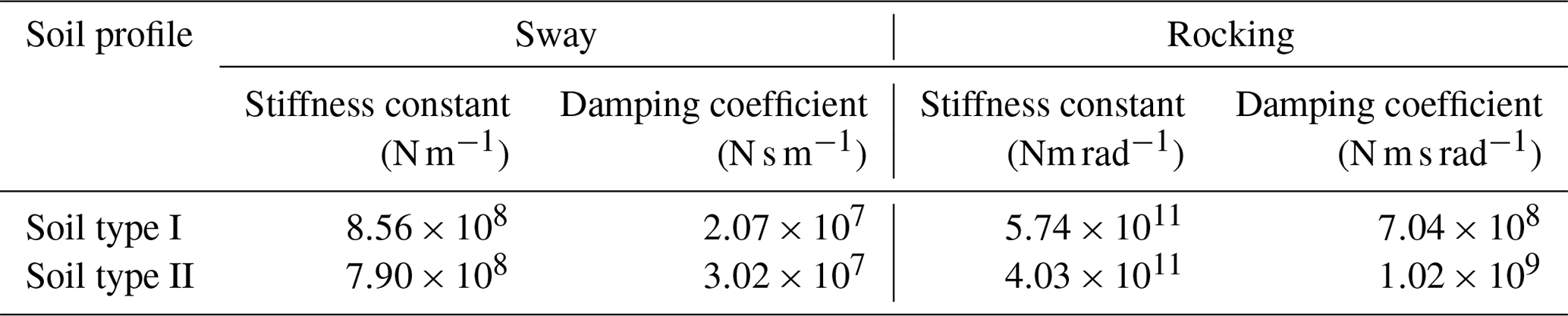
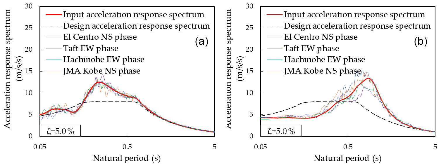
Figure 3Input acceleration response spectra at the footing bottom: (a) Soil type I and (b) Soil type II.
Figure 3 depicts the input acceleration response spectra at the footing bottom obtained for both soil profiles, together with the design acceleration response spectrum at the bedrock condition. In these response spectra, the damping ratio is assumed as ζ=0.05 and the soil amplification factor Gs is estimated by Okano and Sako (2013). Compared with the design response spectrum at the bedrock condition, the input response spectrum is amplified in the short period range less than 0.5 s for Soil type I and in the long period range larger than 0.5 s for Soil type II. Note that the response spectra in Fig. 3 are not directly employed for RSM, but instead, the damping correction factor Fζ is estimated for each modal damping ratio by Eq. (4) and is multiplied with these response spectra to estimate the seismic response of each mode. On the other hand, 15 simulated waves are generated from the design response spectrum considering different phase properties. The four simulated waves utilize the phase properties of famous observed earthquake records, called El Centro NS, Taft EW, Hachinohe EW, and JMA Kobe NS (Building Performance Standardization Association, 2022; Japan Meteorological Agency, 2022), and the other 11 simulated waves utilize random phase property. The input ground motions at the footing bottom are then obtained for both soil profiles from the simulated waves by the equivalent linearization method using DYNEQ (Yoshida and Suetomi, 2014), which allows similar analysis as SHAKE (Schnabel et al., 1972). It is important to note that the shear strain is less than 1 % for both soil profiles, and thus the use of the equivalent linearization method is reasonable for both soil profiles. The acceleration response spectra of the four input ground motions with the phase properties of the observed earthquake records are also shown in Fig. 3. It can be seen that the response spectra of these input ground motions indicate good agreement with the input acceleration response spectrum, implying that the obtained input response spectra properly represent the input ground motions. However, they vary due to differences in the phase properties, in particular for Soil type II. Such variability of the input ground motions can result in the variability of seismic loadings acting on wind turbine support structures by THA using these input ground motions. In the proposed RSM, the uncertainty of the input ground motions is considered by the quantile value γ in the damping correction factor.
Table 5Modal properties of the 2 MW wind turbine support structures.
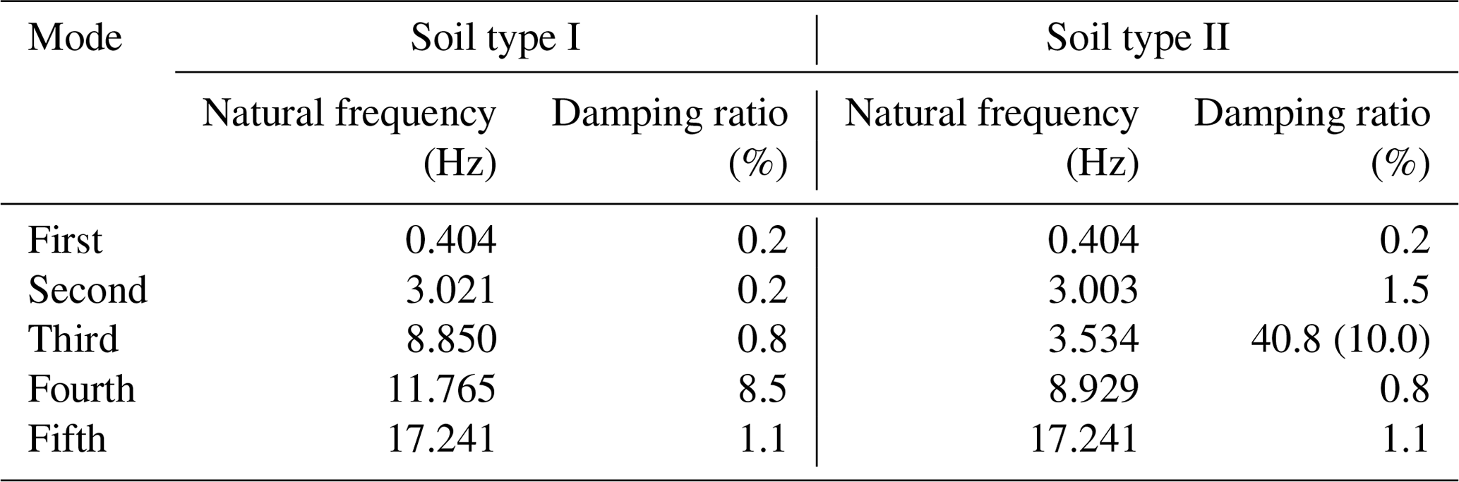
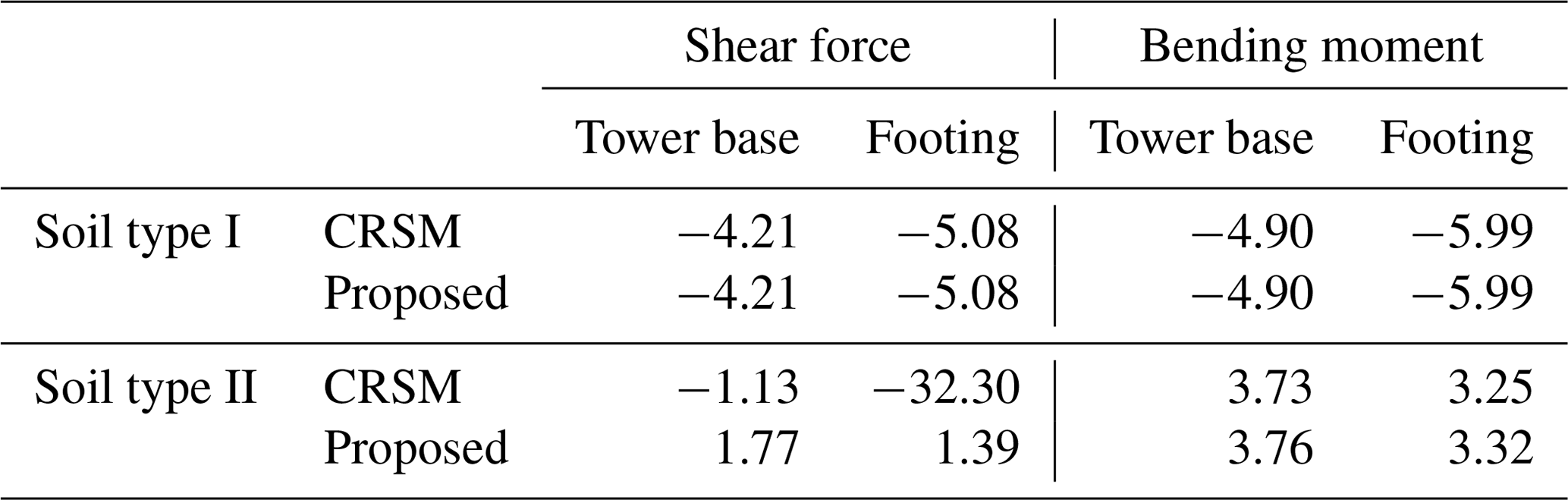
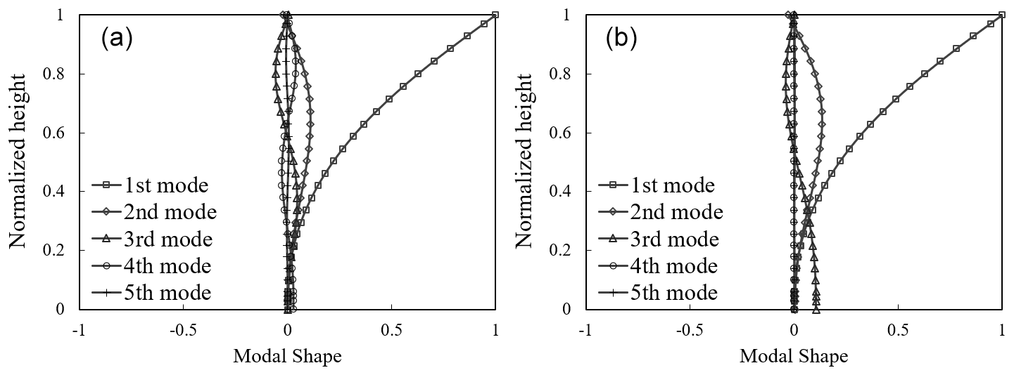
Figure 4Real parts of complex modal participation functions: (a) Soil type I and (b) Soil type II.
Table 5 details the first five natural frequencies and modal damping ratios of the 2 MW wind turbine support structures obtained by solving a complex eigenvalue problem. In addition, the real parts of corresponding modal participation functions Djϕj, for , are depicted in Fig. 4. Note that considering up to the fifth mode fulfils the criteria of Model Code for Concrete Chimneys (CICIND, 2011). It can be seen that all the modal damping ratios are less than 10 % for the case where Soil type I is considered, while an excessive damping ratio larger than 40 % arises at the third mode for the case where Soil type II is considered. As can be seen in the modal participation function shown in Fig. 4b, this mode corresponds to the sway motion of the footing, and thus it can be considered that the excessive damping ratio arising at this mode is caused by the soil radiational damping. Contrary to that, for the case where Soil type I is considered, the sway motion of the footing arises in the fourth mode, while the amplitude of the sway motion is relatively small as shown in Fig. 4a. Hence, the contribution of the soil radiational damping is not so large, resulting in the relatively small modal damping ratio. In the following procedure, the above excessive value of the modal damping ratio is substituted with 10 % by Eq. (16) as provided in the parentheses in Table 6 to avoid the underestimation of the shear force acting on the footing.
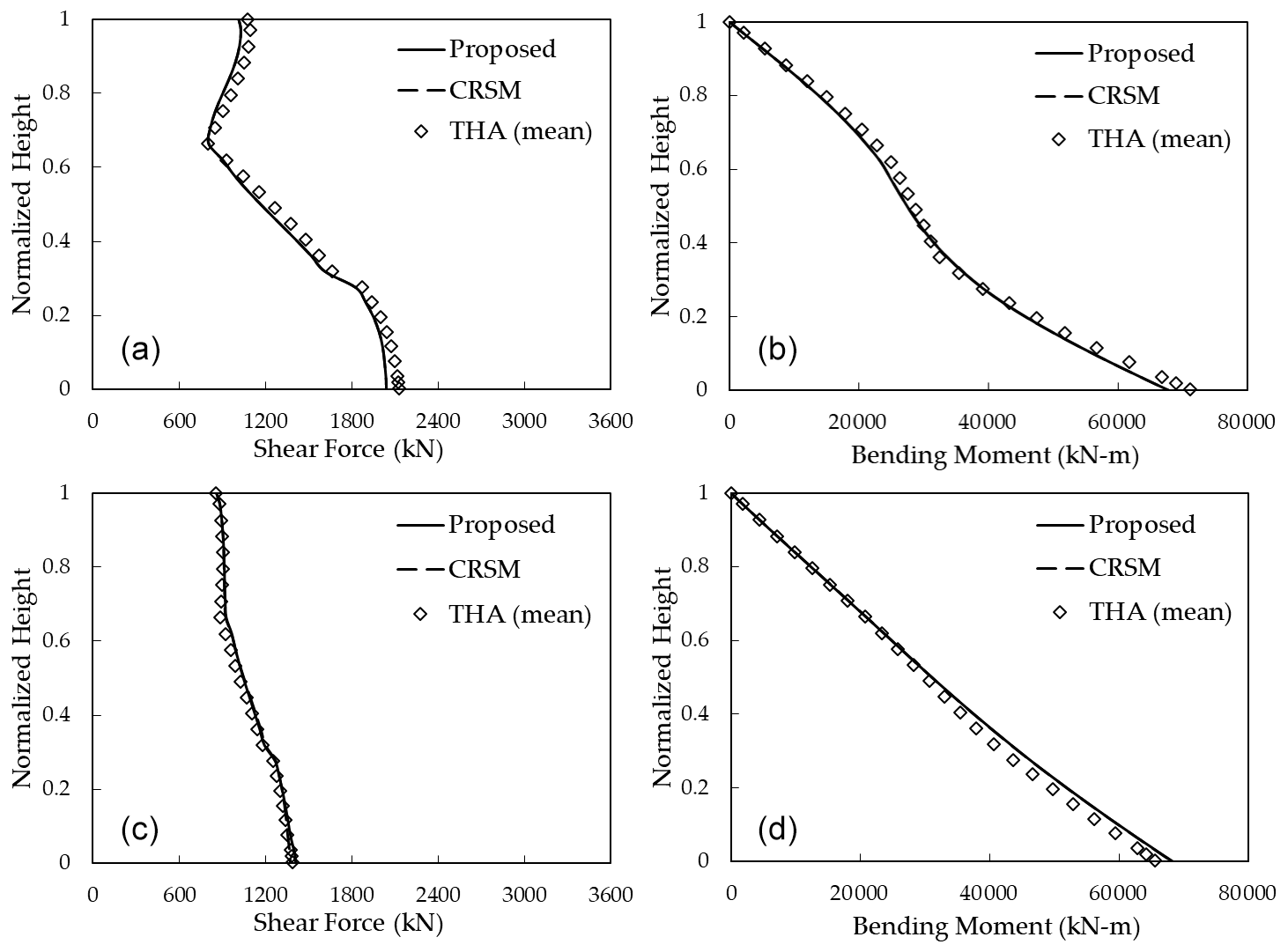
Figure 5Mean profiles of seismic loadings on the tower: (a) shear force for Soil type I, (b) bending moment for Soil type I, (c) shear force for Soil type II, and (d) bending moment for Soil type II.
Figure 5 illustrates the mean profiles of the maximum shear force and bending moment acting on the tower estimated by the proposed method, together with the those obtained by THA using the 15 input ground motions. To demonstrate the effect of the proposed empirical formula of the modal damping ratios in Eq. (16), those estimated by Eq. (15) based on the modal damping ratios obtained by Eq. (7) instead are also shown in this figure. It is noted that this approach is hereafter termed as CRSM. In the proposed method and CRSM, the quantile value in the damping correction factor is set as γ=0.5 to estimate the mean profiles. It can be seen that the proposed method and CRSM result in similar profiles which both show favourable agreement with the results by THA, demonstrating that Eq. (15) is capable of accurately estimating the seismic loadings on the tower. As investigated in Kitahara and Ishihara (2020), the first and second modes that correspond to the sway motion of the tower are dominant on these seismic loadings, and the damping ratios of those modes are both less than 10 %. Therefore, the proposed method herein degrades into CRSM. On the other hand, Fig. 6 depicts a comparison of the mean values of the shear force and bending moment acting on the footing that are obtained by the proposed method, CRSM, and THA. It can be seen that the proposed method and CRSM result in similar values which show favourable agreement with those obtained by THA, excluding the shear force for the case where Soil type II is considered. The accurate estimates of the bending moments can be explained similarly as the aforementioned case, since the first and second modes are dominant on them (Kitahara and Ishihara, 2020). Comparatively, the fourth mode for the case where Soil type I is considered and the third mode for the case where Soil type II is considered both correspond to the sway motion of the footing and are dominant on the shear forces. In the former case, the fourth modal damping ratio is less than 10 %; thus, the proposed method degrades into CRSM, and both can result in an accurate estimate. In the latter case, however, the third modal damping ratio is excessively larger than 10 %; thus, CRSM leads to the significant underestimate. In the proposed method, this excessive damping ratio is hence substituted with 10 % to avoid such underestimations, and the resultant estimate of the shear force consequently coincides well with that obtained by THA.
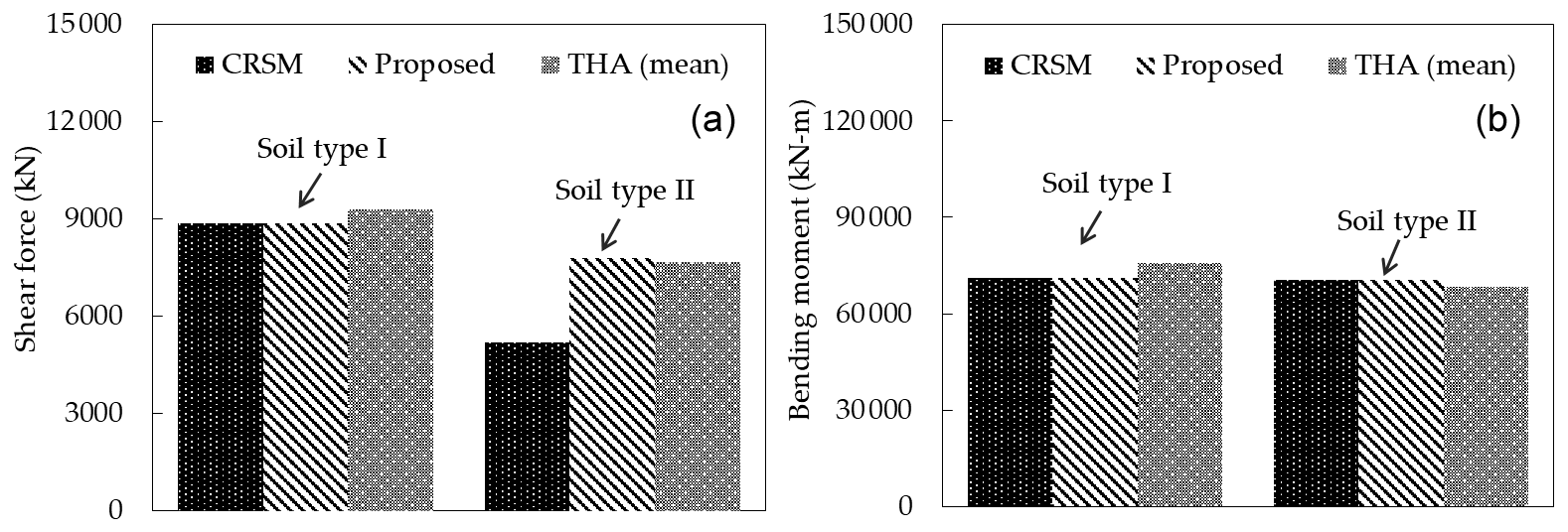
Table 6 summarizes prediction errors in the seismic loadings at the tower base and footing by the proposed method and CRSM compared with the results by THA. As can be seen, the prediction accuracy of the proposed method is quite good, and prediction errors are less than 6 % for all cases regardless of the soil profile, whereas CRSM significantly underestimates the shear force on the footing and the prediction error is larger than 30 %.
In addition, the additional loadings to consider the contribution of the mass moment of inertial of RNA and P−Δ effect are estimated using Eqs. (17) and (19). In Eq. (17), the mass moment of inertial RNA is assumed as Iy=3814.3 kN. Figure 7 illustrates the mean profiles of the maximum bending moment acting on the tower by the proposed method with the above additional loadings, together with the mean results by THA of the full FE model that includes the detailed configuration of the rotor and nacelle. It can be seen that these two profiles estimated by the proposed procedure show favourable agreement with those by THA, implying that the proposed additional loadings can accurately consider the mass moment of inertial RNA and P−Δ effect. Table 7 presents the additional loadings due to the P−Δ effect at the tower base (k=2) and the ratios of those additional loadings to the bending moments at the tower base. It can be seen that is less than 3 % for both soil profiles, and thus the P−Δ effect can be ignored in the practical application.
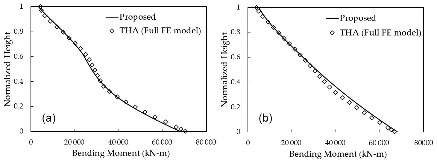
Figure 7Vertical profiles of bending moments on the tower considering the additional loadings: (a) Soil type I and (b) Soil type II.
Table 7Additional loading by the P–Δ effect at the tower base.

4.2 Parametric study for different tower geometries and soil conditions
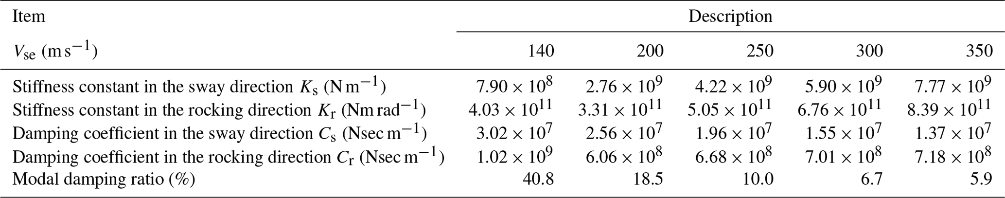
To further demonstrate the recommended threshold value, ζthr=0.1, of the allowable modal damping ratios in the proposed method, a parametric study is conducted by changing tower geometries and soil conditions. First, for considering differences in tower geometries, the rated power of the wind turbine is varied as 1, 1.5, 2, 2.5, and 3 MW based on the configuration of the 2 MW piled foundation supported wind turbine. Table 8 shows the outline of the five wind turbines constructed based on Xu and Ishihara (2014). Note that the shape of the piles is assumed same as that shown in Fig. 2 for all wind turbines. Second, for considering differences in soil conditions, the equivalent S-wave velocity of the soil model is varied as 140, 200, 250, 300, and 350 m s−1 based on Soil type II, whose equivalent S-wave velocity is 140 m s−1 as shown in Kitahara and Ishihara (2020). The 2 MW piled-foundation-supported wind turbine is used for all cases. Table 9 shows the parameters of the springs and dashpots given for each soil model. Moreover, the damping ratios of the most dominant mode on the shear force on the footing are summarized for each case in the last row of these two tables. It can be seen that the modal damping ratios vary from 6 % to 58 %.
Table 8The outline of the piled-foundation-supported wind turbines with different rated powers.
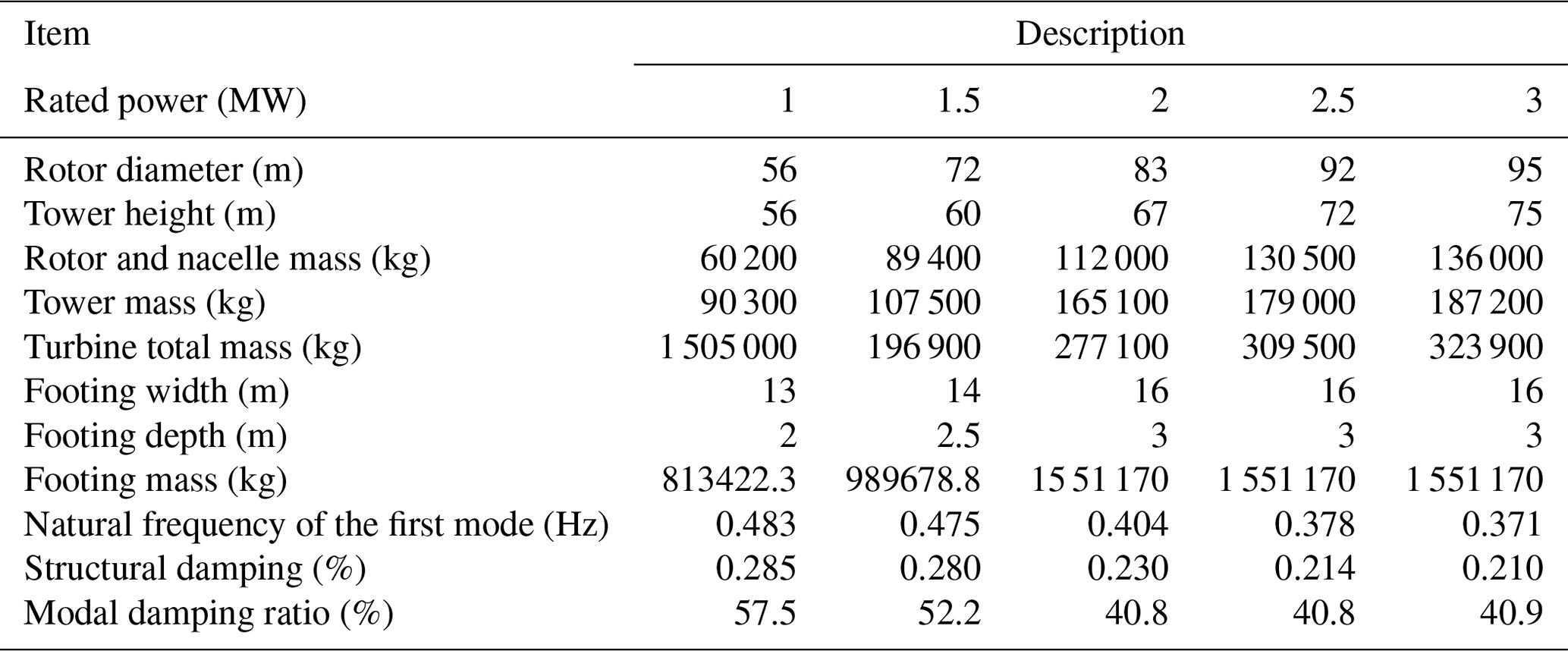
Table 9The outline of the piled-foundation-supported wind turbines with different rated powers.
As candidate values for the threshold ζthr of the modal damping ratios, 0.05, 0.1 (proposed), and 0.15 are investigated. Figure 8 plots the normalized shear forces that are obtained by dividing the maximum shear forces estimated from RSM by those obtained from THA for all the cases summarized in Tables 8 and 9. It can be seen that, if the modal damping ratio of the most dominant mode on the shear force is less than 10 %, CRSM (i.e. no threshold is employed) can accurately estimate the shear force with relative errors less than 10 %, while otherwise it significantly underestimates the shear force, implying that it is necessary to use the proposed formula of the modal damping ratios in Eq. (16) to suppress the underestimation. On the other hand, if the threshold value ζthr=0.05 is chosen for Eq. (16), the shear force is significantly overestimated for the cases where the modal damping ratio is larger than 18.5 %, and, if the threshold is set as ζthr=0.15, it is still relatively underestimated, with relative errors larger than 10 % for the cases where the modal damping ratio is larger than 40.8 %. In contrast, if the threshold ζthr=0.1 is selected, the shear force is accurately estimated with relative errors less that 10 % for all cases, indicating that 0.1 is a reasonable choice for the threshold value ζthr of the modal damping ratios to estimate the shear force acting on the footing with a satisfactory accuracy.
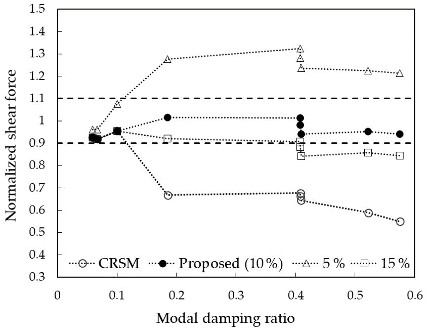
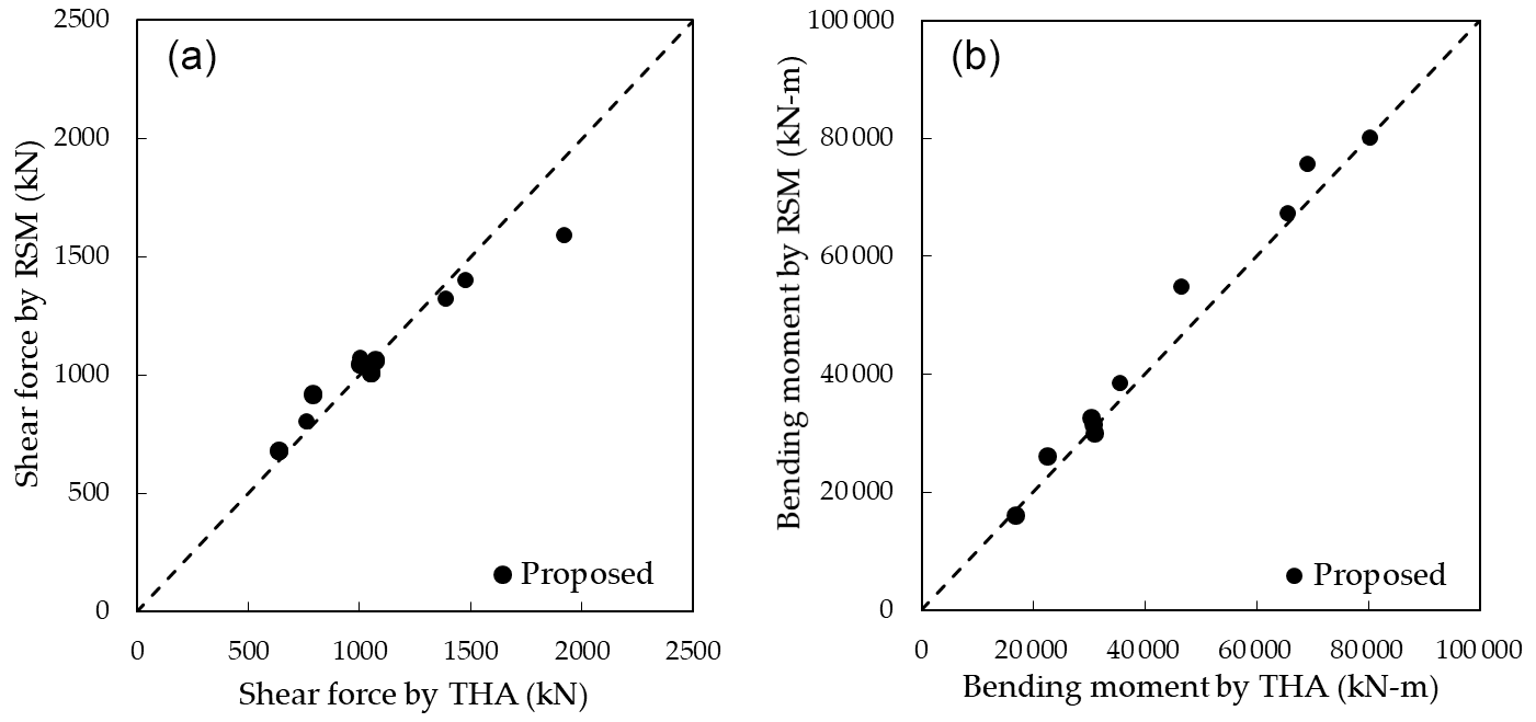
Figure 9The comparison of seismic loadings on the tower by the proposed method and THA: (a) shear forces and (b) bending moments.
Finally, Fig. 9 depicts a comparison of the mean values of the maximum shear forces and bending moments at one-half the height and tower base estimated by the proposed method, where threshold ζthr=0.1 is considered, and THA to demonstrate the estimation accuracy of the seismic loadings acting on the tower based on the proposed method. It can be seen that, for all the cases, the estimates of the seismic loadings on the tower by the proposed method show favourable agreement with those by THA. Consequently, the novel augmented complex mode superposition RSM is demonstrated to be capable of accurately and efficiently estimating seismic loadings on wind turbine support structures.
In this study, the seismic SSI of wind turbine support structures is investigated based on the complex mode superposition approach, where the SR model is employed to model them as a non-classically damped system. To estimate seismic loadings on the tower and footing analytically, an augmented complex mode superposition RSM is proposed based on CRSM that has been developed by Gao et al. (2020). The proposed method is demonstrated on the typical 2 MW wind turbine supported by different types of foundations, i.e. the gravity and piled foundations. Furthermore, the parametric study changing the tower geometries and soil conditions is carried out for demonstrating the recommendation value for the threshold in the empirical formula of the modal damping ratios proposed in this study. Some conclusions of this study are summarized below.
-
The maximum shear force and bending moment of the non-classically damped system are analytically formulated by the proposed method. These formulae are demonstrated on the 2 MW wind turbine support structures, and it is shown that they are capable of estimating seismic loadings on the tower and footing with a satisfactory accuracy.
-
Additional loadings to consider the contribution of the mass moment of inertia of RNA and P−Δ effect to the bending moment on the tower are analytically formulated by the proposed method and are demonstrated by the comparison with the full FE model including the detail configuration of the rotor and nacelle.
-
An empirical formula of the modal damping ratios with a threshold value of the allowable damping ratio is proposed to suppress underestimation of the shear force on the footing due to the excessive modal damping. The parametric study demonstrates that 0.1 is a reasonable choice for the allowable modal damping ratio when the modal damping ratios of the most dominant mode on the shear force on the footing are larger than 10 %.
The source code of the simulations can be requested by contacting the authors.
MK did the conceptualization and design of this work, performed the simulations, and wrote the draft manuscript. TI revised and edited the manuscript and supervised the work.
The contact author has declared that neither they nor their co-author has any competing interests.
Publisher's note: Copernicus Publications remains neutral with regard to jurisdictional claims in published maps and institutional affiliations.
This research was carried out as a part of the joint project supported by ClassNK, J-POWER, Shimizu Corporation, Toshiba Energy Systems & Solutions Corporation, and MHI Vestas Offshore Wind Japan. The authors express their deepest gratitude to the concerned parties for their assistance during this study.
This paper was edited by Michael Muskulus and reviewed by two anonymous referees.
American Society of Civil Engineers: Minimum design loads for buildings and other structures, ASCE/SEI 7-05, Reston, VA, 2006.
Architectural Institute of Japan: Seismic response analysis and design of buildings considering dynamic soil-structures interaction, Maruzen, Tokyo, ISBN 9784818905658,, 2006 (in Japanese).
Ashford, S. A., Boulanger, R. W., Donahue, J. L., and Stewart, J. P.: Geotechnical quick report in the Kanto plain region during the March 11, 2011, Off Pacific Coast of Tohoku Earthquake, Japan, Geotechnical Extreme Events Reconnaissance, Berkeley, CA, GEER Association Report no. GEER-025a, http://learningfromearthquakes.org/2011-03-11-tohoku-japan/images/2011_03_11_tohoku_japan/pdfs/QR1_GEER_Quick_Report_April_5_2011.pdf (last access: 20 April 2022), 2011.
Bazeos, N., Hatzigeorgiou, G. D., Hondros, I. D., Karamaneas, H., Karabalis, D. L., and Beskos, D. E.: Static, seismic and stability analysis of a prototype wind turbine steel tower, Eng. Struct, 24, 1015–1025, 2002.
Building Performance Standardization Association: Typical observed seismic waves (acceleration data), http://www.seinokyo.jp/jsh/top/ (last access: 20 April 2022), 2022 (in Japanese).
Butt, U. A. and Ishihara T.: Seismic load evaluation of wind turbine support structures considering low structural damping and soil structure interaction, Proc. EWEA, EWEA2012, 1–9, 2012.
Chopra, A. K.: Dynamics of structures: theory and applications to earthquake engineering, 4th edn, Prentice Hall, Englewood Cliffs, ISBN-13 9780132858052, 2011.
CICIND: Model Code for Concrete Chimneys. Part A, The Shell, International Committee on Industrial Chimneys, Switzerland, ISBN 1902998138, 2011.
De Domenico, D. and Ricciardi, G.: Dynamic response of non-classically damped structures via reduced-order complex modal analysis: Two novel truncation measures, J. Sond Vib., 454, 169–190, 2019.
Der Kiureghian, A.: A response spectrum method for random vibration analysis of mdof systems, Earthq. Eng. Struct. Dyn., 9, 419–435, 1981.
Eurocode 8: Design of Structures for Earthquake Resistance – Part 1: General Rules, Seismic Actions and Rules for Buildings, EN-1998-1, European Committee for Standardization, Brussels, ISBN 0 580 45872 5, 2004.
Foss, K. A.: Co-ordinates which uncouple the equations of motion of damped linear dynamic systems, J. Appl. Mech., 57, 361–364, 1958.
Francis, A. J.: Analysis of pile groups with flexural resistance, J. Soil. Mech. Found. Div., 90, 1–32, 1964.
Gao, Z., Zhao, M., Du, X., and Zhao, X.: Seismic soil-structure interaction analysis of structure with shallow foundation using response spectrum method, B. Earthq. Eng., 18, 3517–3543, 2020.
Gazetas, G. and Dobry, R.: Horizontal response of piles in layered soils, J. Geotech. Eng., 110, 20–40, 1984.
Harukigaoka Wind Power Inc.: A prompt report on No.2 wind turbine tower damage in Kugino Wind Farm, http://www.meti.go.jp/shingikai/sankoshin/hoan_shohi/denryoku_anzen/newenergy_hatsuden_wg/pdf/009_05_00.pdf (last access: 20 April 2022), 2016 (in Japanese).
IEC61400-1: 4th edition: Wind turbine generator systems Part 1, Safety requirements, International Electrotechnical Commission, ISBN 978-2-8322-6253-5, 2019.
Ishihara, T. (Ed.): Guidelines for design of wind turbine support structure and foundations, Japanese Society of Civil Engineers, ISBN 978-4-8106-0705-5, 2010 (in Japanese).
Ishihara, T. and Wang, L.: A study of modal damping for offshore wind turbines considering soil properties and foundation types, Wind Energy, 22, 1760–1778, 2019.
Ishihara, T., Takamoto, G., and Sarwar, M. W.: Seismic load evaluation of wind turbine support structures with consideration of uncertainty in response spectrum and higher modes, Prof. OFFSHORE, OFFSHORE2011, 1–9, 2011.
ISO 4354: Wind actions on structures, International Organization for Standardization, 2009.
Japan Meteorological Agency: Strong seismic waveform (the 1995 Southern Hyogo Prefecture Earthquake), https://www.data.jma.go.jp/svd/eqev/data/kyoshin/jishin/hyogo_nanbu/, last access: 20 April 2022 (in Japanese).
Kitahara, M. and Ishihara, T.: Prediction of seismic loadings on wind turbine support structures by response spectrum method considering equivalent modal damping and reliability level, Wind Energy, 23, 1422–1443, 2020.
Oh, S. and Ishihara, T.: Structural parameter identification of a 2.4 MW bottom fixed wind turbine by excitation test using active mass damper, Wind Energy, 21, 1232–1238, 2018.
Okano, H. and Sako, Y.: Proposal of evaluation method for amplification of response spectrum by surface strata, J. Technol. Design, 19, 47–52, 2013 (in Japanese).
Randolph, M. F.: The response of flexible piles to lateral loading, Géotechnique, 31, 247–259, 1981.
Schnabel, P. B., Lysmer, J., and Seed, H. B.: SHAKE a computer program for earthquake response analysis of horizontal layered sites, University of California, Berkeley, Report No. EERC72-12, https://www.resolutionmineeis.us/documents/schnabel-lysmer-seed-1972 (last access: 20 April 2022), 1972.
Stamatopoulos, G. N.: Response of a wind turbine subjected to near-fault excitation and comparison with the Greek Aseismic Code provisions, Soil. Dyn. Earthq. Eng., 46, 77–84, 2013.
The building centre of Japan: The Building Standard Law of Japan, ISBN 978-4-88910-169-0, 2016.
Wolf, J. P.: Soil-structure-interaction analysis in the time domain, Nucl. Eng. Des., 111, 381–393, 1989.
Xu, N. and Ishihara, T.: Analytical formulae for wind turbine tower loading in the parked condition by using quasi-steady analysis, Wind Eng., 38, 291–309, 2014.
Yoshida, N. and Suetomi, I.: DYNEQ: A computer program for dynamic response analysis of level ground by equivalent linear method, Tohoku Gakuin University, Version 3.35, 2014.
Zhao, M., Gao, Z., Wang, J., and Zhong, Z.: Response spectrum method for seismic soil-structure interaction analysis of underground structure, B. Earthq. Eng., 17, 5339–5363, 2019.
Zhou, X. Y., Yu, R. F., and Dong, D.: Complex mode superposition algorithm for seismic responses of non-classically dampled linear MDOF system, J. Earthq. Eng., 8, 597–641, 2004.