the Creative Commons Attribution 4.0 License.
the Creative Commons Attribution 4.0 License.
 | 04 Feb 2022
A fully integrated optimization framework for designing a complex geometry offshore wind turbine spar-type floating support structure
Mareike Leimeister
Maurizio Collu
Athanasios Kolios
Spar-type platforms for floating offshore wind turbines are considered suitable for commercial wind farm deployment. To reduce the hurdles of such floating systems becoming competitive, in situ aero-hydro-servo-elastic simulations are applied to support conceptual design optimization by including transient and non-linear loads. For reasons of flexibility, the utilized optimization framework and problem are modularly structured so that the setup can be applied to both an initial conceptual design study for bringing innovative floater configurations to light and a subsequent optimization for obtaining detailed designs. In this paper, a spar floater for a 5 MW wind turbine is used as the basis. The approach for generating an initial but very innovative conceptual floater design comprises the segmentation of the floating cylinder into three parts, the specification of a freer optimization formulation with fewer restrictions on the floater geometry, and the allowance for alternative ballast materials. The optimization of the support structure focuses primarily on cost reduction, expressed in terms of the objective to minimize the floater structural material. The optimization results demonstrate significant potential for cost savings when alternative structural and manufacturing strategies are considered.
- Article
(1688 KB) - Full-text XML
- BibTeX
- EndNote


With floating support structures for offshore wind turbines, more offshore wind resources can be captured and used for power generation, as around 60 % to 80 % of the ocean areas cannot be exploited with bottom-fixed structures, which are limited to water depths of up to around 50 m (European Wind Energy Association, 2013). Floating offshore wind technology is no longer in its infancy. Over the last decade, the technology readiness level of floating offshore wind turbine (FOWT) systems has significantly increased, so that “floating offshore wind is coming of age”, as WindEurope states in its floating offshore wind vision statement (WindEurope, 2017, p. 4). The large number of research studies, research projects, scaled model tests, prototype developments, and full-scale model test phases paved the way towards this current status. More than 40 floating foundation concepts exist and are under development, of which only a few are already used in pilot floating wind farms (Quest Floating Wind Energy, 2020; Future Power Technology, 2019; James and Ros, 2015; Mast et al., 2015). For further speeding up of the market uptake of floating offshore wind farms, significant cost reductions are still required.
While the spar-buoy concept is already very convenient for volume production and certification due to its simple geometry, this technology has to be further advanced to benefit from a wider range of possible installation sites, simplified handling (both construction, assembly, transport, and installation), reduced levelized cost of energy (LCoE), and improved system motion performance (Leimeister et al., 2018). The advancement can be realized in a number of ways. Both Hirai et al. (2018) and Yamanaka et al. (2017) use a three-segmented advanced geometry spar, where a larger diameter column makes up the middle part to allow for shortening the overall length of the spar and reducing the system cost. In contrast, Zhu et al. (2019) utilize the three elements just the opposite way (the spar element as the middle part, interconnecting a slightly larger bottom column and a large upper column), focusing on increased restoring and improved motion performance. In the Fukushima Floating Offshore Wind Farm Demonstration Project FORWARD, an advanced spar-type support structure – consisting of a spar with a column each at the bottom, in the middle, and at the upper end – for a floating substation (Fukushima Kizuna) allows for utilization at around 110 m water depth, improved motion performance, and reduced installation cost (Wright et al., 2019; Yoshimoto and Kamizawa, 2019; Yoshimoto et al., 2018; James and Ros, 2015; Matsuoka and Yoshimoto, 2015; Maine International Consulting LLC, 2013). A similarly structured advanced spar, equipped with damping fins for stabilization in sway and heave direction, was initially used for a 5 MW wind turbine (Fukushima Hamakaze); however, after some investigations and studies by Matsuoka and Yoshimoto (2015), the middle column was removed to optimize the system's restoring, motion performance, and construction cost (Yoshimoto and Kamizawa, 2019; James and Ros, 2015; Maine International Consulting LLC, 2013). Other advancements are inspired by the oil and gas industry and deal with, for example, truss spar platforms, in which a truss section connects a bottom tank with the floating platform and heave plates can be included (Chen et al., 2017; Perry et al., 2007; Bangs et al., 2002), or added helical strakes for improving the dynamic response of the FOWT system (Ding et al., 2017b, a). The advanced spar-type floater by the Massachusetts Institute of Technology (Lee, 2005), on the other hand, has a relatively shallow draft and gets stability support from a two-layered taut-leg mooring system, which goes beyond the common delta or so-called crowfoot connection of the mooring lines to the spar-buoy structure (Butterfield et al., 2007). Furthermore, an additional tuned mass damper (He et al., 2019) or moon pool (Pham and Shin, 2019) can advance the common spar floater.
To obtain an advanced spar-type floater through optimization, most research approaches are based on the common cylindrical spar-type floater shape and utilize gradient-based methods (Dou et al., 2020; Hegseth et al., 2020; Berthelsen et al., 2012; Fylling and Berthelsen, 2011) or genetic algorithms (Karimi et al., 2017; Choi et al., 2014). Some applications solely deal with the support structure, with a focus on either basic hydrodynamic analyses, maximum system stability, and minimum material cost (Choi et al., 2014), decreased draft, weight, and cost while increasing power output (Lee et al., 2015) or optimized floater cost and power generation (Gao and Sweetman, 2018). Other design optimization approaches, in turn, are highly complex: some account for optimizing several components of the FOWT system (e.g., the tower, mooring system, power cable, and/or blade-pitch controller in addition to the floating platform) and focus on extreme loads, structural strength, fatigue life, or power quality in addition to costs and global system responses (Dou et al., 2020; Hegseth et al., 2020; Sandner et al., 2014; Fylling and Berthelsen, 2011). Others also distinguish between different floater types (Karimi et al., 2017; Sclavounos et al., 2008). Even if a reduced draft is often aimed at (Hegseth et al., 2020; Gao and Sweetman, 2018; Lee et al., 2015; Sandner et al., 2014) and sometimes the spar-buoy floater is subdivided into several cylindrical sections (Hegseth et al., 2020; Berthelsen et al., 2012; Fylling and Berthelsen, 2011) or a broad range of allowable values are considered for the design variables (Karimi et al., 2017; Sclavounos et al., 2008), common spar-type platform designs are always considered, meaning a structure consisting of welded sections, for which reason even Hegseth et al. (2020) limit the maximum allowable taper angle.
Thus, this paper aims to demonstrate that through a freer optimization formulation with in situ aero-hydro-servo-elastic simulations, more potential solutions for an advanced spar-type floater design with a higher degree of innovation can be captured, while already including transient and non-linear loads in the analysis. The conceptual design study and optimization approach, applied in this work, focus on hydrodynamic and system-level analyses but do not yet include an optimization of the mooring system. Due to the conceptual character of this study, which precisely targets exploring novel design spaces, stringent limitations on the structure and dimensions are not yet required. The optimization approach followed in this paper is based on an initial design optimization example by Leimeister et al. (2020b), which, however, is quite simple and does not include any aspects or goals for going beyond and advancing the common spar-buoy floater design but only focuses on optimizing the global system performance. While global system performance criteria still have to be fulfilled but are only incorporated as constraints, the main objective of this study is cost reduction – expressed in terms of the material used – and the optimization problem is specified in such a way that advancements, which go beyond just obtaining a reduced draft, can be achieved. Hence, as a result of allowing design variables to have a wider range of values, contemplating different ballast materials, and considering novel structural realization approaches for the resulting optimized geometries, new potential and innovative floater design alternatives – not limited to (conventional) spar-type floaters – emerge. All these requirements regarding design variables and optimization criteria are – together with specific environmental conditions and the fully coupled aero-hydro-servo-elastic dynamic characteristics of a FOWT system – incorporated into a fully modular optimization framework. Its current capability is sufficient for this conceptual design study; however, due to its close interlinking with the fully modular and multi-fidelity numerical modeling environment, the framework can easily be extended to serve more holistic FOWT system design optimization problems of higher fidelity, including a subsequent detailed design development.
To figure out in detail the required characteristics of such a floating platform, first (Sect. 2), a reference FOWT system with corresponding modifications and assessment criteria towards more innovative design solutions is specified, on which basis the optimization problem – consisting of design variables, objective function, and constraints – can be defined. Subsequently, the automated design optimization of the advanced spar-type FOWT system is performed in Sect. 4, including some preprocessing automated design load case (DLC) simulations, as well as the characterization of the automated optimization framework and the iterative optimization approach. The results of the optimization simulations are presented in Sect. 5 and further discussed in Sect. 6. Finally, some conclusions are drawn in Sect. 7.
According to the survey conducted by Leimeister et al. (2018), industry professionals and scientific experts judge the advanced spar-type floater – compared to the common spar-buoys, semi-submersibles, tension leg platforms, barges, or any hybrid, multi-turbine, or mixed-energy floating system – to be the most suitable wind turbine support structure for deployment in floating offshore wind farms. To prepare the fully modular optimization problem setup, by means of which problems at various levels of fidelity – such as, in this first instance, the conceptual design study on innovative floater configurations – can be addressed, both the reference FOWT system (Sect. 2.1) and the advancement options (Sect. 2.2) need to be defined.
2.1 Reference floating offshore wind turbine system and numerical model
As a starting point of the design optimization towards an innovative floating platform for an offshore wind turbine, a traditional spar-buoy FOWT system, taken from phase IV of the OC3 (Offshore Code Comparison Collaboration) project (Jonkman, 2010) with the main properties provided in Appendix A, is used. This is further modified, as explained in Sect. 2.2, to allow the realization of advanced features and the development of an innovative spar-type structure.
An aero-hydro-servo-elastic coupled model of dynamics of this reference spar-buoy FOWT system is developed and verified by Leimeister et al. (2020a), using MoWiT (Modelica library for wind turbines) (Fraunhofer IWES, 2022), which is developed at the Fraunhofer Institute for Wind Energy Systems (IWES) (Leimeister and Thomas, 2017; Thomas et al., 2014; Strobel et al., 2011). The modeling approach in MoWiT utilizes the object-oriented, equation-based, and component-based modeling language Modelica (Modelica Association, 2021) and, therefore, follows a hierarchical structure with interconnected main components and subcomponents to represent the complex wind turbine system and corresponding fully coupled system dynamics in accompanying time-domain simulations. This multibody approach provides high flexibility to model various wind turbine system types, environmental conditions, and simulation settings by simply modifying single model components and, hence, forms the basis for an approach to a framework towards multi-fidelity.
2.2 Design modifications for facilitating advancements and innovative floater configurations
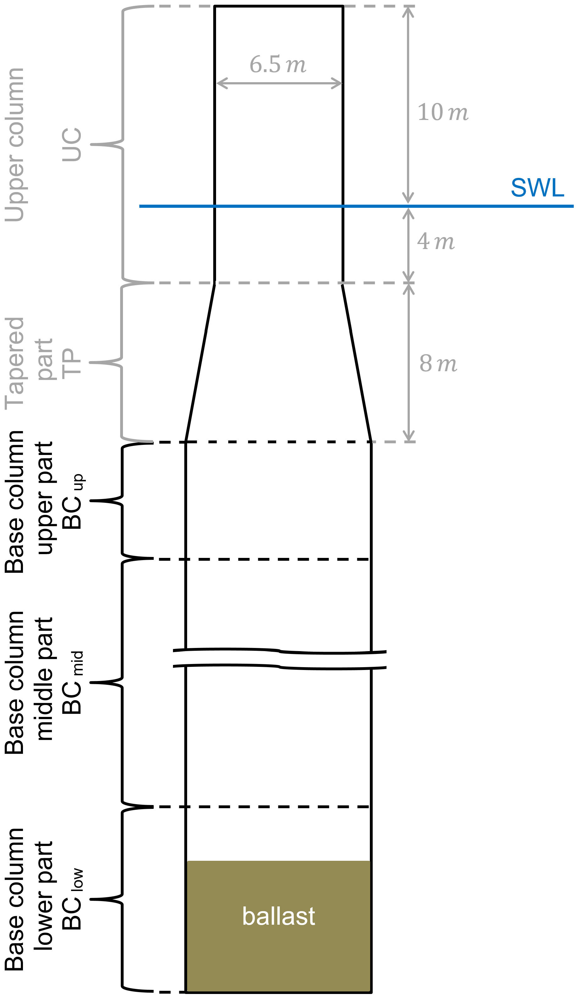
The MoWiT model of the OC3 phase IV spar-buoy FOWT system (Sect. 2.1) is used as a basis and modified to facilitate advancements so that innovative floater designs can be obtained through automated optimization. Because this work focuses on the design of the floating structure rather than the mooring system, a shorter, lighter, and thus less expensive platform design shall be obtained by changing the floater geometry and allowing for more advanced features, which will be addressed in detail in Sect. 3. Different characteristic shapes of advanced spar-type floating platforms are pointed out in Sect. 1. In this study, a similar concept as presented by Zhu et al. (2019) and realized in the Fukushima Hamakaze FOWT system (Matsuoka and Yoshimoto, 2015; Yoshimoto and Kamizawa, 2019) is applied. Thus, the long cylindrical element beneath the tapered part is divided into three partitions: (1) the base column upper part BCup, which shall serve to gain buoyancy; (2) the base column middle part BCmid, which shall mainly serve to separate the other two parts in order to deepen the position of part 3; and (3) the base column lower part BClow, which can be filled with ballast and shall shift the center of gravity downwards. This partitioning is schematically represented in Fig. 1, showing the unchanged geometric parameters and dimensions for the upper column (UC) and tapered part (TP) in a light shade (gray) and indicating the three sections of the base column (BC) together with the ballast filling in the base column lower part BClow.
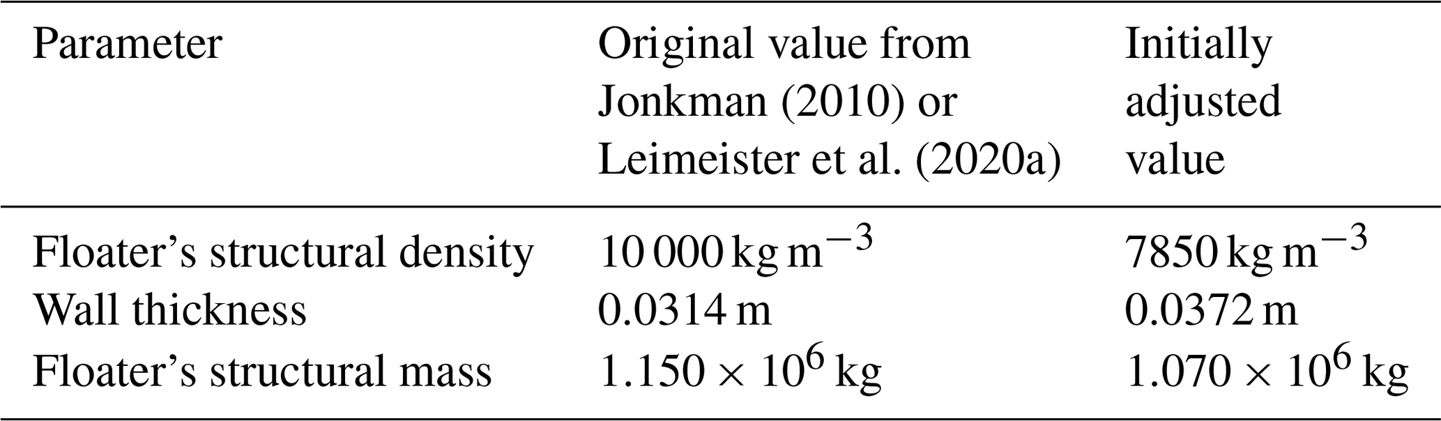
Apart from these modifications, which are directly related to advancements in the geometric configuration, the material density of the support structure and the wall thickness of the cylindrical spar-buoy elements are also changed. As the material density of the OC3 phase IV spar-buoy is not explicitly stated in the definition document (Jonkman, 2010), a value of 10 000 kg m−3 is derived in the model verification study (Leimeister et al., 2020a). However, to better match the common steel properties of offshore structures, a material density of 7850 kg m−3 is used in this study. Furthermore, the wall thickness of the spar1 is changed from the fixed value of 0.0314 m, which is derived by Leimeister et al. (2020a), to a wall thickness that is adaptable to the specific floater configuration. To obtain an appropriate wall thickness for a corresponding floater design, a fixed ratio of the support structure's structural mass to the displaced mass of water is deployed. For a spar-type floating platform, this ratio is 0.13, according to representative values from research designs and academic studies and excluding designs, such as the Hywind demonstrator, which are, for safety reasons, heavily oversized (Bachynski, 2018). Hence, the equivalent structural mass of the spar-type floater (meaning the mass of the spar-type steel structure, excluding tower, wind turbine, and ballast) with certain outer dimensions (diameters Di and heights Hi) and corresponding displaced volume can be determined following Eq. (1).
This results in a structural mass of 1.070×10⁶ kg, which is a bit lower than the original structural mass of 1.150×10⁶ kg (Leimeister et al., 2020b). The corresponding appropriate wall thickness, which is kept the same for all parts of the specific floater geometry, is computed by means of Eq. (2). This equation is derived from the expression for the floater's structural mass, using a material density of 7850 kg m−3 as explained earlier. In Eq. (2), Hi and Di are the heights and diameters of each element, meaning UC, TP, BCup, BCmid, and BClow. However, the diameter of the tapered part DTP is calculated using Eq. (3) as the mean of the diameters of UC and BCup.
This way, a wall thickness of 0.0372 m is obtained for the initially adjusted OC3 phase IV spar-buoy with reduced material density (7850 kg m−3) and an adopted structural mass-to-displaced mass ratio of 0.13. This thickness value lies within the acceptable range, based on available data for the OC4 (Offshore Code Comparison Collaboration Continuation) phase II semi-submersible floater. The initially adjusted parameter values are summarized in Table 1 in comparison to the values of the original OC3 phase IV FOWT system.
Jonkman (2010)Leimeister et al. (2020a)Table 1Comparison of original and initially adjusted FOWT system parameters.
As the conceptual design (optimization) study does not focus on the mooring system, as already mentioned, and due to the fact that the mooring system itself could be covered in a separate or subsequent detailed design optimization task, any change in the restoring system characteristics due to shifted fairlead positions is prevented by utilizing constant (the original) resulting mooring system properties. This means that – independent of possible attachment points to the reshaped floating platform – the resulting stiffness of each mooring line is taken from the system motion, assuming the original fairlead positions as defined in Sect. 2.1. A realistic mooring system design for the finally obtained optimized floating platform, which represents the considered resulting mooring system properties, can then be obtained through a subsequent optimization. This might even happen manually, depending on the degree of complexity, as it is applied in studies for designing equivalent mooring systems (Molins et al., 2015; Udoh, 2014). However, having not included the optimization of the mooring system within this study, further system performance improvements due to modified mooring system parameters or fairlead positions – in addition to an optimized support structure design – are limited. This, however, leaves open the possibility of subsequent fine tuning of the conceptual design solution obtained through optimization based on hydrodynamic and system-level analyses. By addressing the mooring system in the subsequent detailed design optimization or even in a successive but separate optimization algorithm, the dynamic response of the FOWT system, as well as the mooring line tension itself, can be significantly improved by considering an advanced and more complex optimization problem, in which – apart from various line diameters and lengths – different mooring line arrangements and distribution forms can be utilized, the optimum number of lines within the mooring system and best fairlead position can be elaborated, different mooring types can be used or even mixed within segmented lines, and also clump weights can be incorporated (Tafazzoli et al., 2020; Barbanti et al., 2019; Men et al., 2019; Chen et al., 2017).
Within this study, the advancements for achieving the conceptual design of an innovative floating platform go beyond the main objectives to reduce the draft of the floater and the cost of the overall system. Further advanced features comprise the investigation of alternative materials, which from an economic point of view are comparable to currently used materials but positively influence the final floater design due to their different material properties and characteristics. Additionally, novel structural approaches, which might be more promising than the common approach of welding cylindrical and tapered sections together and allow a widening of the design space for such innovative floater shapes, are considered. In this conceptual design study, any detailed structural integrity checks are not yet addressed. However, due to the multi-fidelity model, optimization problem, and framework setup, these can be added easily for a more extensive optimization approach in a subsequent detailed design study. The advantage of focusing right now only on hydrodynamics and global system performance without defining any restrictions regarding structural aspects is that floater designs, which would have been discarded when performing structural integrity checks and as they would be impossible to realize with conventional structural approaches, can still be captured as potential solutions when considering different structural realization approaches.
From the advancements and associated assessment criteria detailed in the following, the modifiable design variables xi collated in the design variables vector X, the objective functions fi to be minimized, and the equality (hi) and inequality (gi) constraints to be fulfilled are derived to set out the optimization problem according to the following formal expressions, in which the functions are either directly dependent on the design variables or also on the resulting fully coupled FOWT system, denoted with system(X).
3.1 Design variables
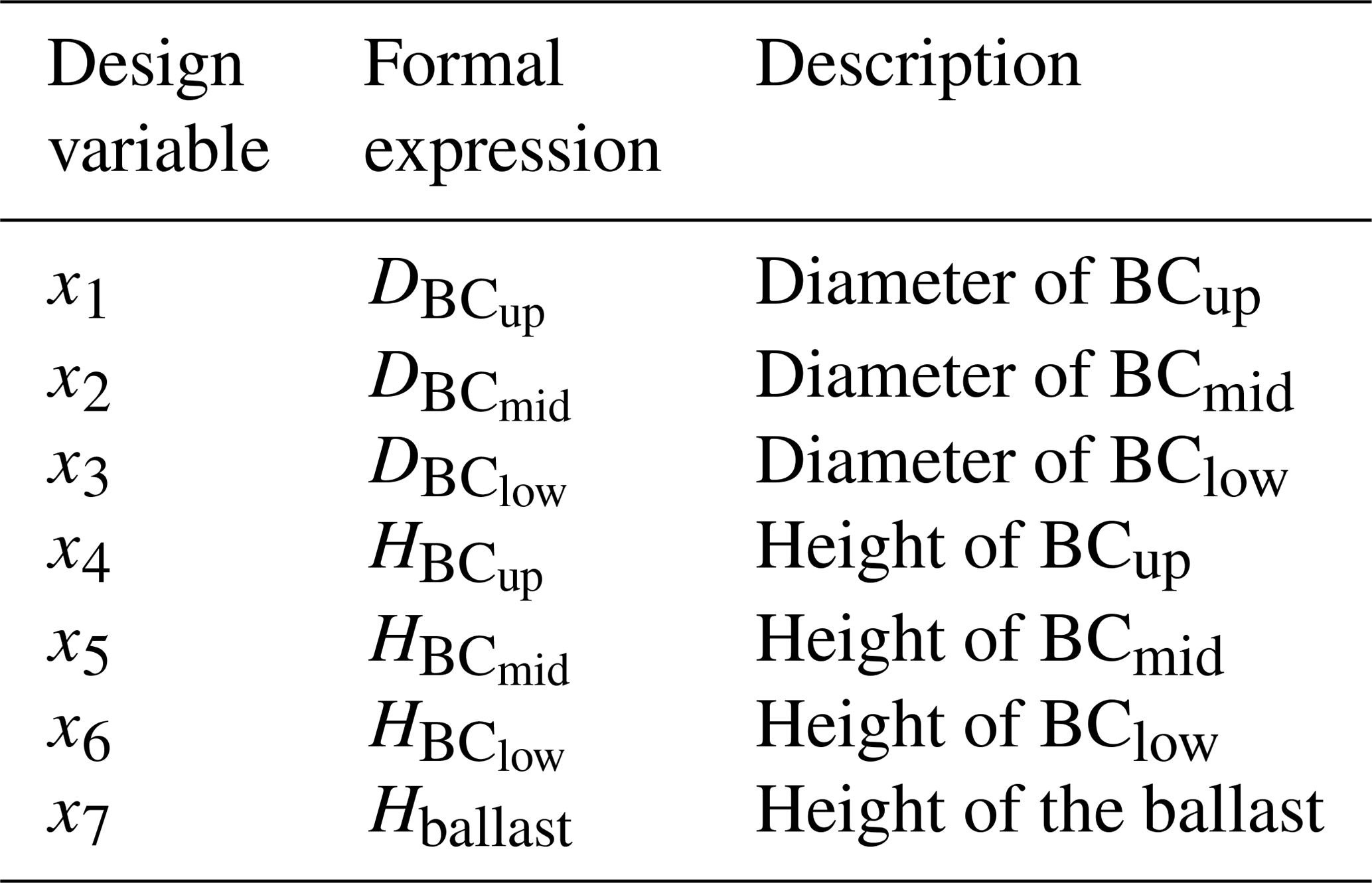
Based on the derivation of the modified spar-buoy floater model (Sect. 2.2) for enabling the incorporation of the considered advancements, seven design variables are defined as presented in Table 2.
3.2 Objective function
The only structurally related focus considered in this approach is the minimization of the structural cost. This is represented by the objective function f1 (Eq. 4), which aims to minimize the structural material volume of the advanced spar-type floating platform.
3.3 Optimization constraints
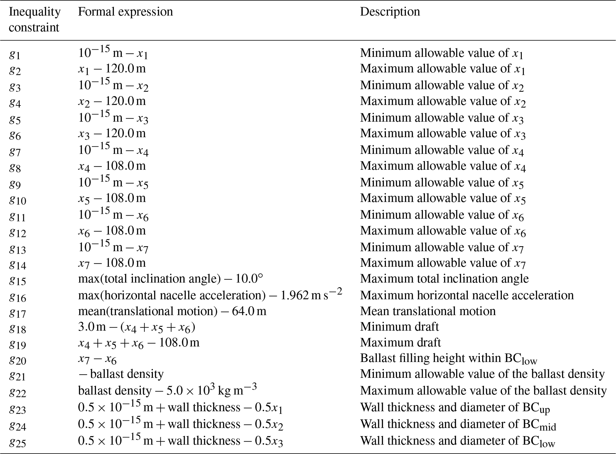
To achieve a shortened length of the floater, the allowable system draft is limited to the original draft of the OC3 phase IV FOWT as its maximum value, as well as to a recommended minimum value of 15.0 m (Ng and Ran, 2016). The resulting allowable total height of the BC (between 3.0 and 108.0 m) has to be distributed among the three partitions. However, no restrictions prevail, and the option of utilizing not all of the three BC parts is also possible. Thus, the minimum allowable value for the height of each of the BC parts is machine epsilon (10−15 m) – as a zero value is unfeasible from a modeling point of view. These requirements with regard to the overall system draft and the heights of each partition are represented in Table 3 by the inequality constraints g18 and g19 as well as g7 to g14, respectively. For the ballast height, it additionally has to be guaranteed that it does not exceed the actual BClow height, implying inequality constraint g20.
The allowable value range for the diameter of each of the BC parts is set from machine epsilon – due to the same modeling feasibility reason – to 120.0 m, leading to the inequality constraints g1 to g6. The maximum diameter is chosen deliberately large – corresponding to the total maximum draft of the floating system – to ensure that the border of feasible solutions is well captured. From a manufacturing point of view, cylindrical offshore structures with diameters of more than 10.0 m are realistic: various sources state a value of 11.0 m (Sif Group, 2020; Windkraft-Journal, 2019) , the reference semi-submersible floating platform from phase II of OC4 has an upper column diameter of 12.0 m (Robertson et al., 2014), and the diameter of the spar-buoy utilized in the Hywind Scotland floating wind farm is even up to 14.5 m (Equinor, 2017, 2020). However, looking at other floating platform solutions, such as the Damping Pool® floater by Ideol (outer dimensions: 36 m × 36 m; resulting diagonal length: almost 51 m) (Ideol, 2020) or the OC4 phase II semi-submersible platform (overall outer dimension: almost 82 m in diameter) (Robertson et al., 2014), shows that floating structures with a large overall outer diameter can be obtained without being restricted to the manufacturing feasibility limits for pure cylinders. Thus, the equivalent hydrodynamic behavior and characteristics of a larger-diameter cylindrical offshore structure can be achieved by several smaller-diameter cylinders being clustered together in a circle. Finally, attention has to be drawn to the minimum possible diameter of the BC parts, which always has to be at least twice the actual wall thickness corresponding to the specific geometric floater configuration. This requirement adds the inequality constraints g23 to g25.
After all these modifications, the ballast density has to be adjusted to match the original floating equilibrium between buoyancy force, system weight, and downward mooring force so that the original hub height is maintained. To exclude unfeasible system solutions, in which material would have to be removed from the system (realized, for example, by reducing the material density) to meet this equilibrium condition, it has to be ensured that the actual resulting ballast density carries a positive value, which is reflected through inequality constraint g21. However, to account for truly realistic ballast densities, the uppermost allowable value of the ballast density also has to be constrained. Leimeister et al. (2020b) have explored densities for common and cheap materials to be used as ballast for a floating spar-buoy. The densest material included is sandstone (or other rocks) with a density of about 2.6×10³ kg m−3. Apart from sand, sand mixed with water, concrete, or rocks, MagnaDense (heavyweight concrete) is also used in industry as a high-density material2 (LKAB Minerals, 2018, 2020). Densities of up to 5.0×10³ kg m−3 can be obtained using MagnaDense (LKAB Minerals, 2019). Even if the optimization objective focuses on the structural cost, the cost of the two potential densest ballast materials is elaborated to avoid significant higher ballast costs when utilizing MagnaDense instead of the common cheap materials pointed out by Leimeister et al. (2020b). However, when comparing the material prices for sandstone (Alibaba.com, 2020a) (for the ballast density limit of 2.6×10³ kg m−3) and MagnaDense2 (Alibaba.com, 2020b) (for the ballast density limit of 5.0×10³ kg m−3), it turns out that both ballast materials have a similar cost of around USD 150 per metric ton, which is less than 20 % of the material cost for structural (raw) steel of about USD 700 per metric ton (Grogan, 2018; Butcher, 2018; Spend On Home, 2018). Thus, the ballast density is constrained to a maximum of 5.0×10³ kg m−3, corresponding to the inequality constraint g22, without worrying about any negative impact on the cost situation.
As particular attention is paid to the global system performance, there are three additional criteria which the FOWT system has to fulfill. For system rotational stability reasons, a maximum total inclination angle of 10.0∘ is allowed in operational conditions (Leimeister et al., 2020b; Katsouris and Marina, 2016; Kolios et al., 2015; Huijs et al., 2013), leading to inequality constraint g15. Furthermore, due to sensitive components in the nacelle and to avoid lubrication issues, the nacelle acceleration is commonly, and depending on the specific wind turbine, limited to a maximum of 0.2 to 0.3 times the gravitational acceleration constant (Nejad et al., 2017; Huijs et al., 2013; Suzuki et al., 2011); in this study, the lower value of 1.962 m s−2 is used for defining the inequality constraint g16, following a conservative approach (Leimeister et al., 2020b). Finally, the static translational displacement of a (non TLP-type) FOWT system, corresponding to the mean of the translational motion, is, based on experience, restricted to 0.2 times the water depth (Leimeister et al., 2020b). With a water depth of 320.0 m for the OC3 phase IV spar-buoy floating system, the mean translational motion is limited to 64.0 m, implying the inequality constraint g17.
The final automated design optimization of the modified reference spar-type FOWT system described in Sect. 2.2 consists of preprocessing automated system simulations for identifying the simulation conditions to be considered within the optimization (Sect. 4.1), as well as the actual iterative optimization approach for obtaining a conceptual innovative spar-type floating platform design (Sect. 4.3). Both steps utilize a framework for automated simulation and optimization developed at Fraunhofer IWES and presented in Sect. 4.2.
Table 4System parameters for preprocessing simulations of selected DLCs (Leimeister et al., 2020b).
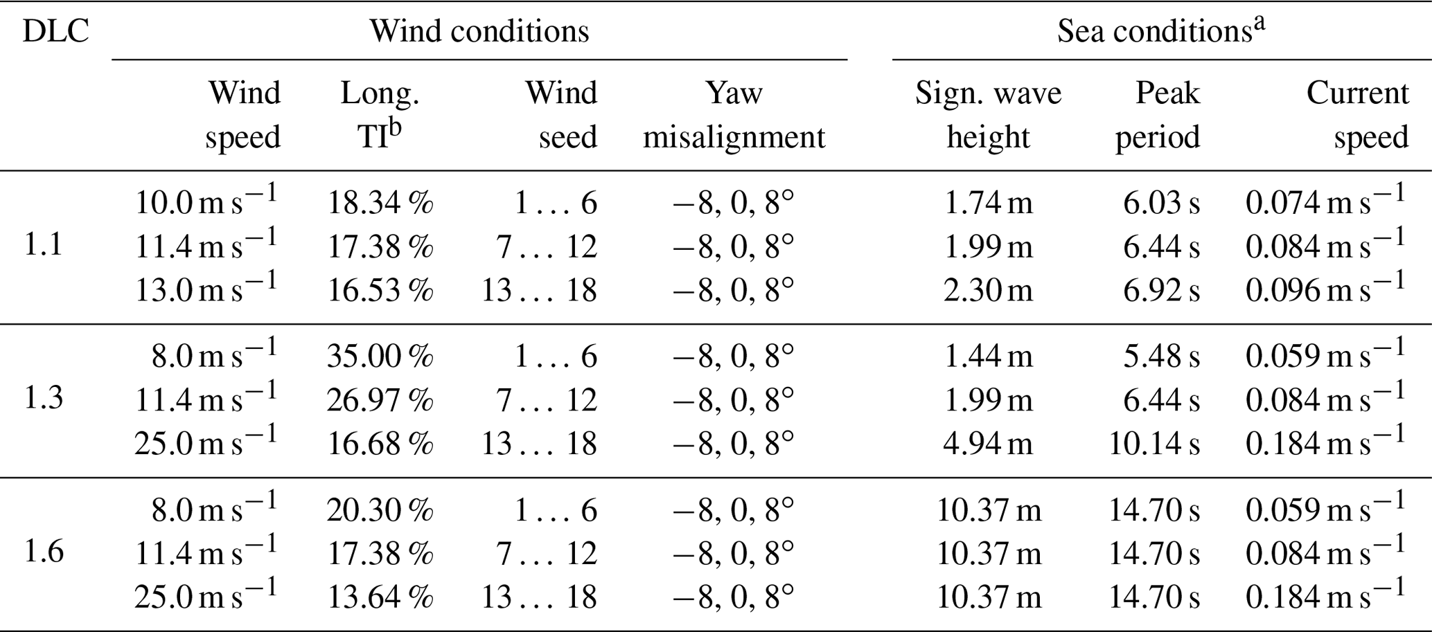
a Please notice that each realization of the turbulent wind with a different wind seed uses a different wave seed as well. b Turbulence intensity.
4.1 Preprocessing automated system simulations
When performing an iterative design optimization approach, it is not practical to simulate the full set of DLCs recommended by standards for each design considered. This is not only for reasons of high computational effort, but also due to the fact that not all DLCs may be relevant or design-driving for the specified optimization problem. Thus, in this work, the same approach as taken by Leimeister et al. (2020b) is adopted. From IEC 61400-3-1 (International Electrotechnical Commission, 2019), DLC 1.1 at three wind speeds closely around the rated wind speed as well as DLC 1.3 and DLC 1.6 – both at below-rated, rated, and cut-out wind speeds – are selected. The reasoning for this is that these DLCs are expected to cover the highest thrust load and corresponding system inclination and mean translational displacement at rated wind speed, as well as maximum dynamic responses in extreme turbulent wind conditions or in severe irregular sea states and, hence, might be critical for the three global performance constraints g15 to g17 (Table 3), which need to be checked and adhered to. By taking six different seeds for turbulent wind and irregular waves for each wind speed considered into account to capture the randomness of the environmental conditions, 54 simulation cases are defined, corresponding to 18 distinct environmental settings per DLC, as summarized in Table 4.
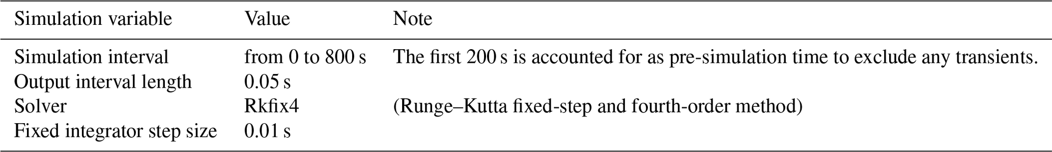
These 54 system simulations have already been performed by Leimeister et al. (2020b) with the original OC3 phase IV floating system and are carried out with the modified reference system from Sect. 2.2 in this study. The simulations are executed automatically, utilizing a fully modular framework, which is introduced in Sect. 4.2. From the total simulation time of 800 s, the last 600 s (excluding any transients at the beginning) is evaluated with respect to the system performance criteria. For the modified reference spar-type floating system, the five highest values for the three performance parameters and corresponding DLC simulation cases, as well as the position of the most critical DLC for the original OC3 phase IV FOWT (DLC 1.6 at rated wind speed with wind seed number 11 and a yaw misalignment angle of 8∘), found by Leimeister et al. (2020b), are presented in Table 5. This shows that the same DLC is still of high criticality for the modified reference spar-type floating system: the total system inclination angle is nearly 96 % of the highest value obtained in the 54 DLC simulations, the horizontal nacelle acceleration is nearly 99 % of the highest value occurring, and the mean translational motion is just less than 1 % lower than the maximum value obtained.
Table 5The highest values for the three performance parameters and corresponding DLC simulation cases, based on the modified reference spar-type FOWT system.
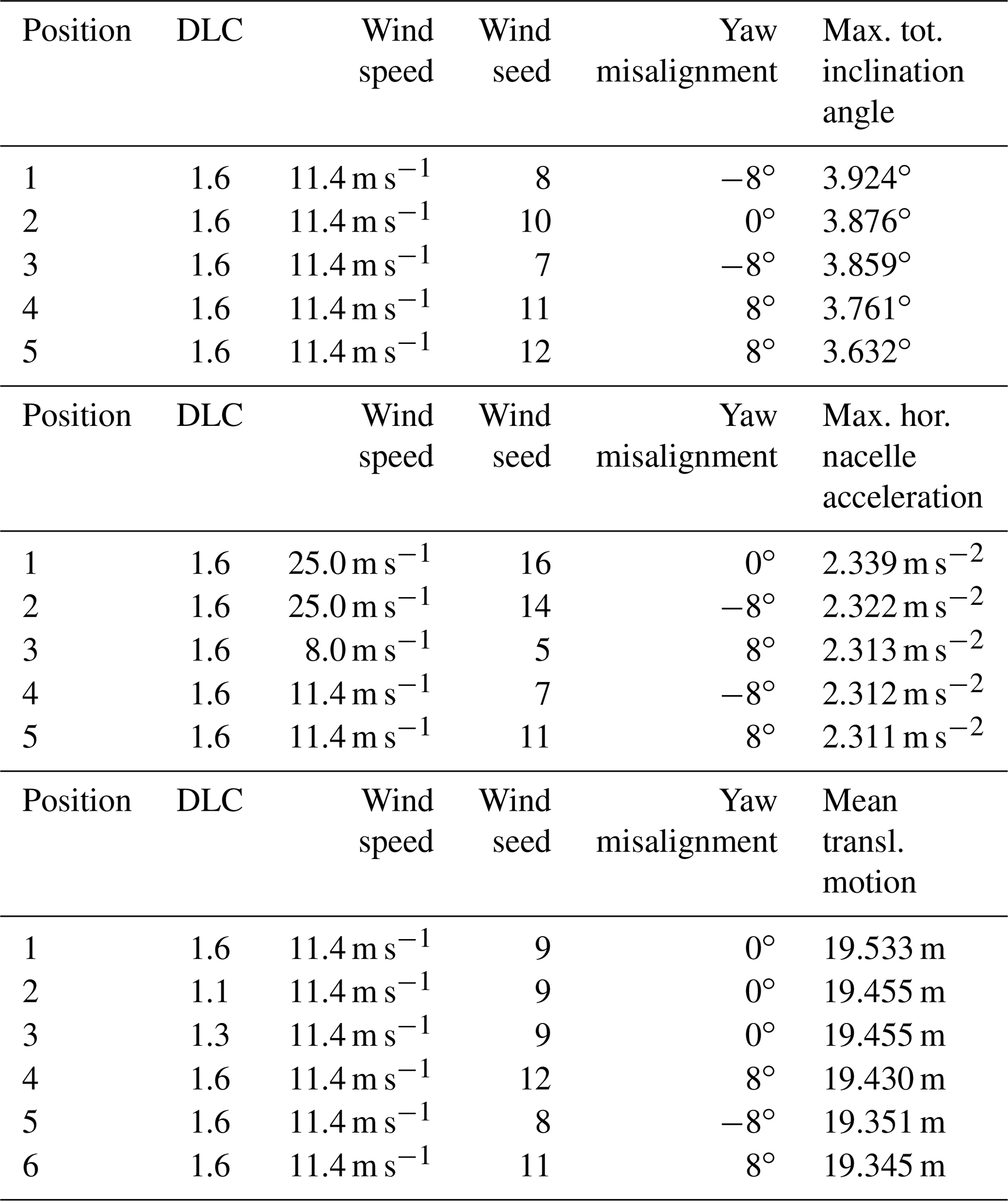
Thus, this DLC 1.6 at 11.4 m s−1 wind speed with wind seed number 11 and a yaw misalignment angle of 8∘ is used for defining the environmental conditions for the system simulations throughout the iterative optimization approach, which is specified in detail in Sect. 4.3. As, however, it is not ensured that the outcome of the DLC results comparison – based on the reference spar-type FOWT system – does not change for the optimized floater design, the 54 environmental conditions will be simulated subsequent to the design optimization process, and the criticality of the DLCs will be assessed again, as covered in Sect. 5.4.
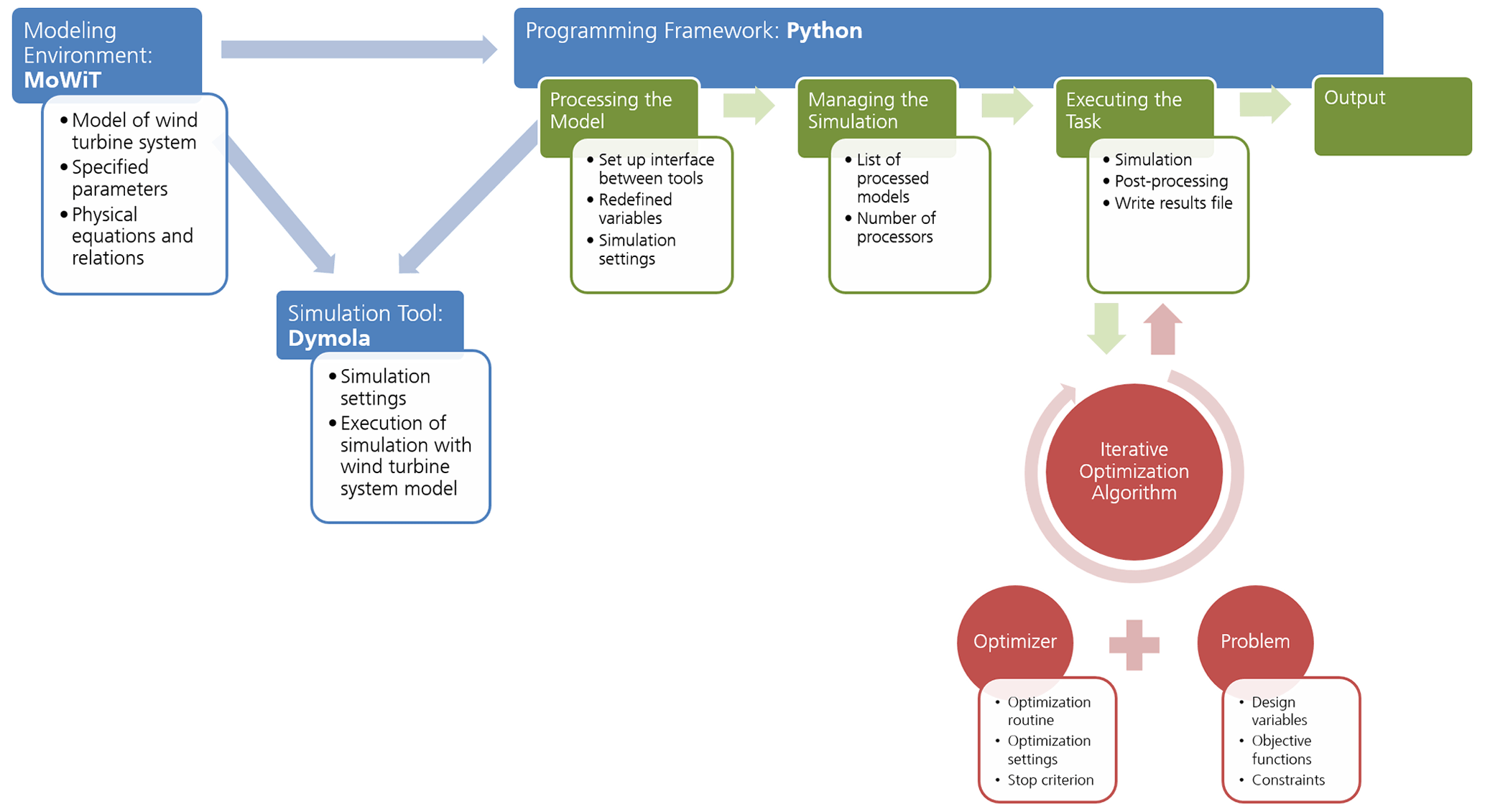
Figure 2The Python–Modelica framework for automated simulation and optimization, adapted from Leimeister et al. (2021).
4.2 Automated optimization framework
The preprocessing DLC simulations (Sect. 4.1), as well as the actual iterative optimization approach (Sect. 4.3), are executed in an automated manner by means of a Python–Modelica framework developed at Fraunhofer IWES (Leimeister et al., 2021; Leimeister, 2019). The structure and components of this framework for automated simulation and optimization are presented in Fig. 2. The framework consists of three modules: a modeling environment, a simulation tool, and a programming framework.
Having modeled the reference spar-type FOWT system, described in Sect. 2.1 and 2.2, in MoWiT, system and environmental parameters, as well as the underlying physical equations and relations, are specified. From the aero-, hydro-, control, and structural dynamic approaches available in MoWiT (Leimeister et al., 2020a), the following ones are utilized in this application: blade-element-momentum theory, including dynamic stall and dynamic wake; linear Airy wave theory, Wheeler stretching, and MacCamy–Fuchs approach; built-in operating control; and modal reduced anisotropic beams for blades and rigid bodies for tower and floating structure.
As the simulation tool, Dymola (Dynamic Modeling Laboratory) by Dassault Systèmes (Dessault Systèmes, 2022), which is capable of time-domain simulations of complex Modelica models, is used.
The programming framework is coded in Python. The implemented scripts follow – as detailed in Fig. 2 – a four-step process for the automated execution of simulations, such as the 54 environmental conditions from Sect. 4.1, and facilitate the option to embed an iterative optimization algorithm, as described in Sect. 4.3. More detailed information on the Python–Modelica framework, regarding both the theory and structure, as well as its capabilities and some application examples, can be found in the publications by Fricke et al. (2021), Leimeister et al. (2021), and Leimeister (2019).
4.3 Specification and execution of the iterative optimization approach
To perform the iterative optimization of the reference FOWT system, the optimization algorithm (Sect. 4.3.1) and workflow (Sect. 4.3.2) need to be specified.
4.3.1 Optimizer
From the broad range of available algorithms and methods (Leimeister et al., 2021), NSGA-II (Non-dominated Sorting Genetic Algorithm II) from Platypus (Hadka, 2015) is selected to be used as the optimizer in this application based on preceding comparative analyses (Leimeister et al., 2020b). The parameterization of the algorithm comprises the number of individuals in each generation (the population size), the strategies for representing the evolution, and the stop criterion for terminating the iterative optimization algorithm. As 60 processors could be used for parallel simulations on the utilized AMD Ryzen Threadripper 2990WX 32-core processor with a 64-bit system and 64 virtual processors, 60 individuals are considered in each generation. The individuals are randomly generated. When evaluating the objective function and constraints, the dominant individuals – each selected based on a comparison of two individuals – form the basis for the next generation, which is created without using any variator. These are the default generator, selector, and variator settings of NSGA-II in Platypus. The stop criterion for terminating the iterative optimization algorithm is defined by the total number of simulations to be performed, while the convergence is checked separately when post-processing the simulation results. As the convergence speed is not known ahead of the execution of the specific optimization problem, the experience from the first-stage design optimization application example (Leimeister et al., 2020b) is used, and the total number of simulations is increased to account for the more complex optimization problem considered in this study. Hence, the resulting number of generations being simulated is roughly tripled, so that a total number of simulations of 10 000 is chosen, corresponding to more than 166 full generations with 60 individuals each.
4.3.2 Optimization workflow
Having modeled the FOWT system (Sect. 2.2), stated the simulation settings (Table 6), defined the optimization problem (Sect. 3), and specified the optimizer (Sect. 4.3.1), the iterative optimization can be executed by means of the Python–Modelica framework for automated simulation and optimization (Sect. 4.2).
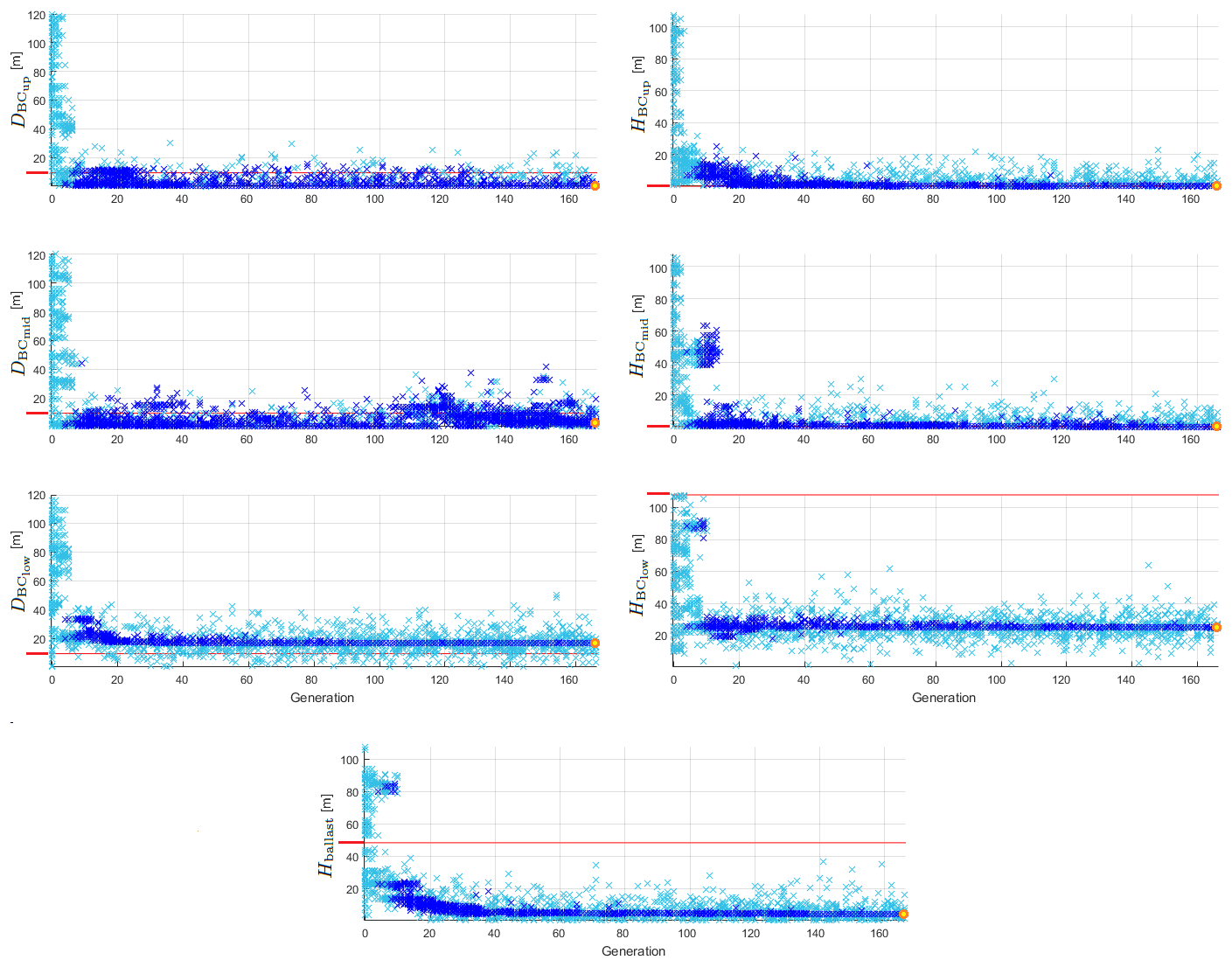
Figure 3Development of the design variables within the iterative optimization process: all simulated individuals are represented by light blue crosses and those complying with all constraints by dark blue crosses, the best-performing individual is marked with a yellow filled circle framed in orange, and the value corresponding to the reference FOWT system is plotted as a red line.
Within the iterative optimization algorithm, the values of the design variables for the 60 individuals of the first generation (number 0) are selected by the optimizer based on the specified allowable value ranges. All individuals are simulated in parallel on the available 60 processors and analyzed afterwards by the optimizer with respect to their fitness – meaning the objective function – and their compliance with the constraints based on the resulting time series, evaluated between 200 and 800 s. As simulations may have failed (due to poor performance of instable floating system designs which demonstrate a negative metacentric height), the simulated time is checked against the specified simulation stop time (800 s according to Table 6). In the event of an unsuccessful simulation and, hence, an incomplete time series, the parameters of interest addressed in the constraints g15 to g17 for system performance are not evaluated but are set to twice the maximum allowable value. This way, it can be ensured that unsuccessful simulations do not comply with all constraints and, hence, are undesirable design solutions, which the optimizer discards from further selection of well-performing individuals.
Having evaluated the simulated individuals of generation 0, the optimizer selects the design variables for the individuals of the next generation (number 1), again in accordance with the specified allowable value ranges, but also based on the fitness and constraint compliance rate of each of the previous individuals, using the tournament selector for evaluating the dominance. Then, the loop of simulating individuals, evaluating each system with respect to the objective function and constraints, and re-selecting values for the design variables of the individuals of the next generation is repeated as long as the number of executed simulations is still below the specified total number of simulations of 10 000. This iterative optimization algorithm ends when the stop criterion is reached; the final results are now available.
The optimization run takes about 31 d and 11 h and comprises 10 011 individuals simulated in total, ranging from generation 0 up to generation 166, with full populations up to and including generation 165.
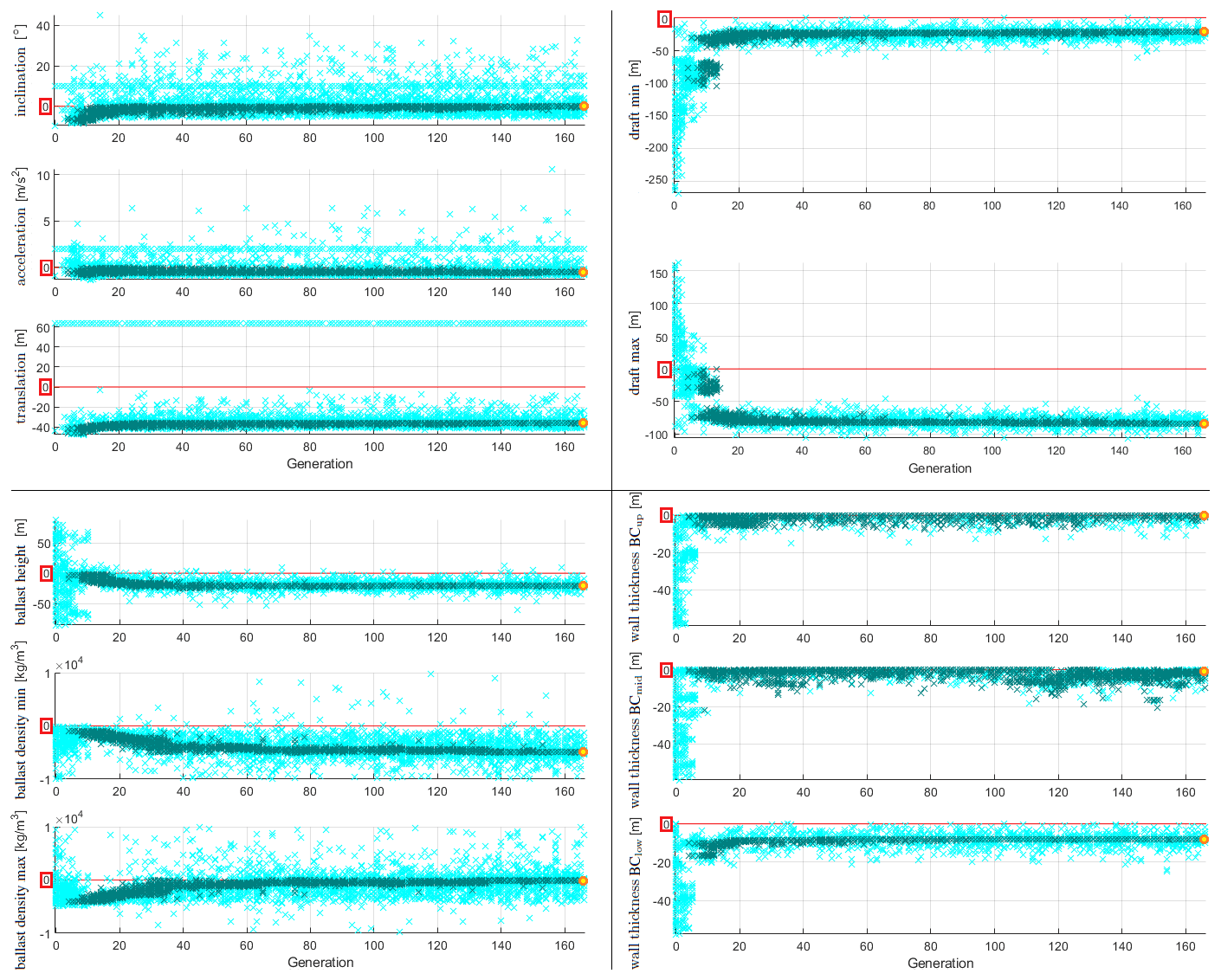
Figure 4Development of the constraints within the iterative optimization process: all simulated individuals are represented by light cyan crosses and those complying with all constraints by dark bluish green crosses, the best-performing individual is marked with a yellow filled circle framed in orange, and the maximum allowable value is plotted as a red line.
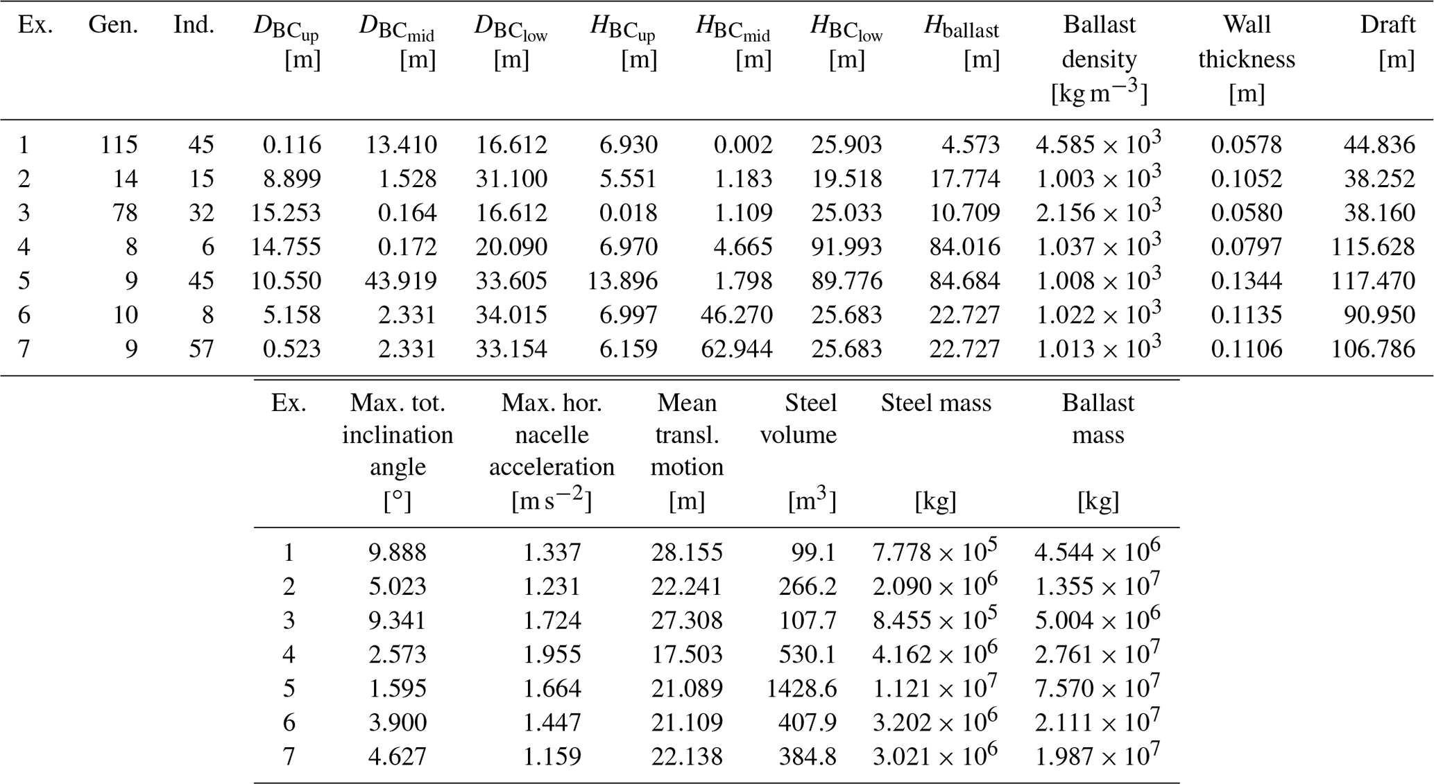
Table 7Key figures of the exemplary potential innovative floater geometries.
5.1 Development within the iterative optimization process
In Fig. 3, the design variable values of all simulated individuals are presented, and the individuals that comply with all specified optimization constraints and the best-performing individual (selected in Sect. 5.3), as well as the original values of the reference FOWT system, are highlighted. The development of the design variables within the iterative optimization process shows that in the first generations, the optimizer selects individuals covering the entire design space; however, none of the first meets all requirements. With more generations, the compliance rate has significantly increased. Overall, the spread in the design variables is decreased for more generations being simulated, and for some design variables, the change in their values is even very limited for the individuals that comply with all constraints. This indicates that the optimization algorithm is converging.
Similarly, Fig. 4 presents the development of the constraints within the iterative optimization process. Since g1 to g14 are taken into account ahead of the simulations when the optimizer selects the design variables for the new individuals and, hence, they are never violated, as can clearly be seen in Fig. 3, only the results of the inequality constraints g15 to g25 are plotted. For g21 and g22 on the ballast density it has to be noted that the ordinate is limited to [, 1×10⁴] for reasons of clarity, as a few more individuals yield values of the order of magnitude of 106. For g18 to g20 (i.e., the draft limits and the constraint on the ballast height) and g23 to g25 (i.e., the compliance checks on wall thickness and diameter), which are directly related to and dependent on the design variables, the development of the constraints and the corresponding design variables are similar. For the other constraints, the trend is rather different, with a large spread in the results. The fact that for the performance constraints g15 to g17 only a few distinguishable individuals are plotted in the first generations is caused by the large number of unstable design solutions that are selected by the optimizer in the first trials. Due to the unsuccessful simulations, the performance variables are set to undesired values, as explained in Sect. 4.3.2, and, hence, they are all the same for all failing systems. This is also visible throughout the generations, as there is a line at the specified undesired value formed by the individuals that do not complete the simulations successfully, which, however, are only a few per generation (two to three in the higher generations).
5.2 Innovative floater geometries in the design space
As presented and mentioned in Sect. 5.1, the individuals of the first generations cover the entire design space, while the individuals that comply with all constraints are in a much narrower area. The geometric design variables of these individuals that meet all constraints are presented in Fig. 5. From these individuals that comply with all constraints, seven examples out of different generations are selected to demonstrate the diversity of potential innovative floater geometries, not yet focusing on their performance with respect to the objective function. These examples are schematically shown in Fig. 5, while the corresponding figures for design variables, performance parameters, objective function, and further resulting geometrical and structural parameters are outlined in Table 7. When evaluating g1 to g25, these figures emphasize once more that none of the inequality constraints are violated.
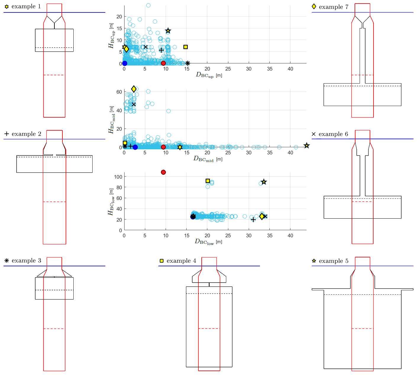
Figure 5Exemplary potential innovative floater geometries selected from the individuals complying with all constraints: the individuals complying with all constraints are represented by unfilled light blue circles, the best-performing individual is marked with a dark blue filled circle, and the value corresponding to the reference FOWT system is plotted as a red filled circle with the associated shape drawn with a red line.

Figure 6Pendulum-stabilized innovative floating platform concepts. (a) Stiesdal's TetraSpar (Borg et al., 2020). (b) Saipem's Hexafloat (Ribuot, 2019).
Looking at the floater geometries presented in Fig. 5, it becomes clear that not all of these shapes can be realized with conventional manufacturing solutions, where cylindrical sections are welded together. It has to be emphasized that these results are solely based on the hydrodynamic and system-level analyses, as specified within the optimization problem, as well as on the advancements taken into account in Sect. 3, which clearly intend the utilization of alternative and innovative structural realization approaches and let the optimizer explore novel configurations that are not necessarily covered by conventional floater manufacturing techniques. Other additional types of analyses – addressing structural integrity, manufacturability, and localized design – would deem some of the presented potential design solutions unfeasible, if they are tailored to conventional spars, as discussed in some more detail in Sect. 6. However, the advantage of this methodology – by focusing only on the global system performance – is that a new range of potential floater designs is opened up, and shapes like those presented in Fig. 5 can still be considered feasible solutions when different structural realization approaches are applied. These approaches can range from truss structures to tendons to realize large diameter changes as well as very thin “distance” elements without utilizing tapered sections or having issues with the structural integrity. Idea and impulse providers for such alternative structural realization approaches can be, for example, the oil and gas industry with truss spar platform design solutions (Chen et al., 2017; Perry et al., 2007; Bangs et al., 2002) or innovative floating platform concepts like the TetraSpar by Stiesdal Offshore Technologies A/S (Fig. 6a) (Borg et al., 2020; Stiesdal, 2019) or the pendulum-stabilized Hexafloat floater (Fig. 6b) by Saipem, realized in the AFLOWT project (Ribuot, 2019; Richard, 2019). Similarly to these two innovative pendulum-stabilized floating platform concepts, example 6 in Fig. 5 would suggest implementing a configuration with a separate ballast body, connected to the main body through braces or tendons. Therefore, this kind of structure cannot be realized with conventional spar manufacturing, but the approach adopted in this paper can shed light on such innovative shapes that may require alternative structural strategies.
5.3 The optimized conceptual floater design
The development of the objective function within the iterative optimization process, as presented in Fig. 7, shows a significant minimization of the objective function – clearly below the original value of 136.3 m3 – after a large spread in the first generations. The individuals that comply with all constraints aggregate to an asymptote with regard to their structural volume. This asymptotic clustering of the individuals that comply with all constraints to a minimum objective function value, on the one hand, states the convergence of the iterative optimization process and, on the other hand, portends that there will be several – more or less similar (elaborated in the following) – design solutions that yield comparable low structural material volumes that are all very close to the minimum value observed.
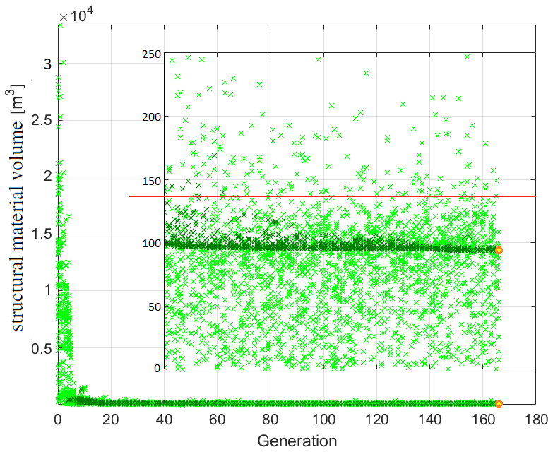
Figure 7Development of the objective function within the iterative optimization process: all simulated individuals are represented by light green crosses and those complying with all constraints by dark green crosses, the best-performing individual is marked with a yellow filled circle framed in orange, and the value corresponding to the reference FOWT system is plotted as a red line.
The individual with the minimum structural material volume yields a reduction of more than 31 % compared to the original (modified) reference spar-type floating platform, for which it must be noted that it has neither been designed with the same design requirements nor yet been optimized. The fact that this optimum solution is just found in the last generation states that the optimizer still tries to improve the result for the objective function since no convergence tolerance has been specified as a stop criterion, and the 10 000 simulations have to be completed. Evaluation of the individuals corresponding to the first 10 minimum objective function results yields – as some individuals yield the same objective function value – 16 individuals with just a % increase in structure material volume compared to the minimum value and shapes that are difficult to distinguish from each other. This demonstrates the abovementioned anticipation and emphasizes the optimization's convergence.
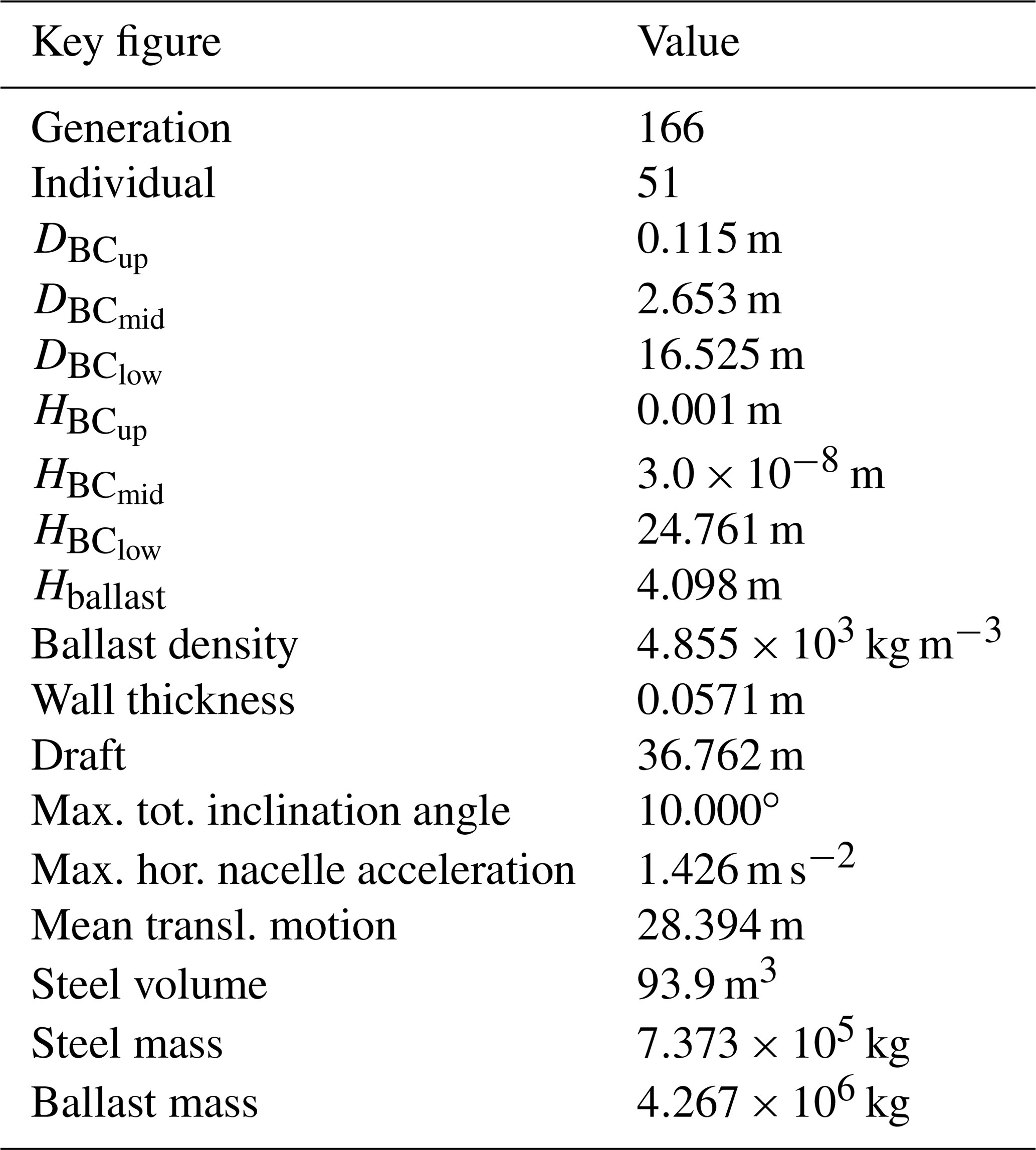
The geometry of the best-performing floater shape is shown schematically in Fig. 8 in comparison to the original floating platform, while the key figures are presented in Table 8. The global system performance points out that the maximum total inclination angle is the most critical criterion, as the value obtained from the optimized design is equal to the specified upper limit of 10∘. With respect to the design development within the optimization process, both Fig. 8 and Table 8 indicate the following advancements: to reduce structure material volume, the overall length of the floating platform is significantly decreased (the draft of the optimized floater, however, is still some way from the minimum allowable draft of 15 m); the width of the bottom part of the support structure is enlarged, while the upper and middle parts are almost left out (leading to this significant constriction in the tapered part); and a very low ballast volume is obtained through a significantly increased ballast density, utilizing MagnaDense or high-density concrete as the ballast material.
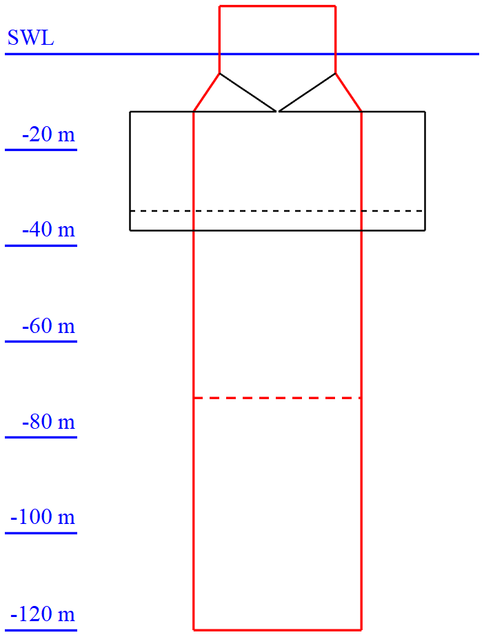
Figure 8The best-performing floater geometry (black) in comparison to the original shape (red).
Overall, the shape of the optimized conceptual floater design rather resembles a thick submerged barge-type floater, hanging below the upper column element. The constriction in the tapered part is significant and would not be directly feasible, both from a manufacturing point of view and with respect to structural integrity. The reason for the current shape obtained is the connection of the upper column to the upper BC part, which, however, is, as well as the middle BC part, negligible. Thus, for this floater configuration, the tapered part could directly connect the end of the upper column with the top of the lower BC part. The change in required structure material would not be that significant; however, the related change in the displaced water volume has to be taken into account by adjusting the structure mass and by carefully evaluating the system performance due to the shifted center of buoyancy. This realization by means of a tapered section, however, comes with a large diameter change and corresponding large taper angle, which may be critical for both hydrodynamic load calculations and manufacturing, as discussed in more detail in Sect. 6. However, the structural issues due to the geometrical configuration of the optimized floater as presented in Fig. 8, or due to the large diameter change when utilizing a tapered section, become void when, instead, connecting the upper column and lower BC part by means of a number of rigid slender braces or some tendons, in combination with plated partial bulkheads for load transfer. These manufacturing solutions go beyond the conventional structural realization approach of welding cylindrical sections together, but they make the found optimized floater design solution feasible and are expected to exhibit similar system performance. The fitness of the floater solution proposed by the optimizer is underlined due to its similarity (with respect to the innovative structural realization approach) to the most novel and alternative solutions suggested by the research community, such as the Stiesdal's TetraSpar (Fig. 6a) (Borg et al., 2020; Stiesdal, 2019) or the Hexafloat by Saipem (Fig. 6b) (Ribuot, 2019; Richard, 2019).
Table 9The highest values for the three performance parameters and corresponding DLC simulation cases, based on the best-performing floating system.
5.4 Performance of the best-performing system in different environmental conditions
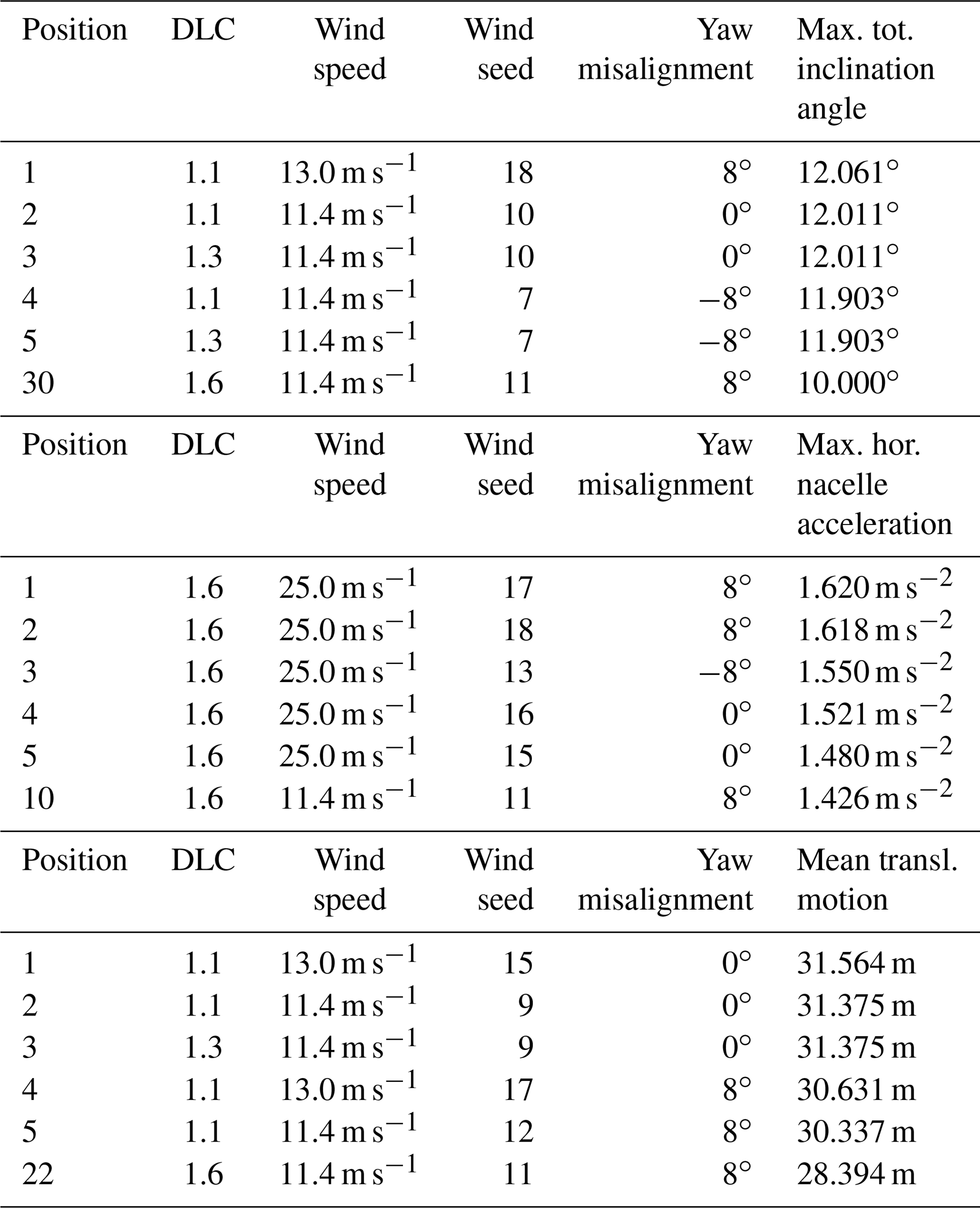
Finally, with the conceptual design solution for the innovative FOWT platform obtained from the optimization run, the DLCs that are selected for the preprocessing automated system simulations for choosing the most critical DLC (as presented in Sect. 4.1) are rerun to check whether a shift in the most critical DLC happened. The criticality is again assessed by evaluating the fully coupled system performance criteria and analyzing the corresponding constraints g15 to g17. The highest values and corresponding DLC simulation cases, as well as the values obtained with the selected critical DLC 1.6 at rated wind speed with wind seed number 11 and a yaw misalignment angle of 8∘, are presented in Table 9.
A shift in the criticality of the DLCs is observed: the smallest change in the criticality order of the 54 environmental conditions happens in the horizontal nacelle acceleration. Still, the cases of DLC 1.6 at cut-out wind speed, as well as around rated wind speed, are the most critical, but the DLC used within the iterative optimization algorithm is still among the first 10, with an acceleration value that is almost 12 % lower compared to the maximum obtained from all simulated DLCs. This, however, is itself more than 17 % below the maximum allowable horizontal nacelle acceleration and, hence, uncritical, which – on a side note – is not the case for the original floating spar-buoy wind turbine system. A significant increase in the resulting performance values and a considerable change in the degree of criticality of the environmental conditions are obtained for the mean translational motion. Here, the selected DLC for the optimization process drops from the original sixth position to the 22nd, while it is just 10 % below the highest value achieved, which is still less than half of the maximum allowable value and, hence, again uncritical. However, the most severe shift in the criticality of the DLCs happens in the total inclination angle. As indicated in Sect. 5.3, the maximum allowable value is already reached in the environmental condition considered for the optimization approach. This DLC, however, is no longer prevailing for the best-performing design solution but just in the 30th position, meaning that 29 other environmental conditions (mostly from DLC 1.1 and DLC 1.3, as well as some others from DLC 1.6) exceed the specified upper limit by up to more than 20 %. In these environmental conditions, the floater design obtained from the optimization run would have to stop operation, while the overall system stability is not expected to be critical, as commonly much higher values for a parked FOWT system in extreme environmental conditions are acceptable, such as 15∘ considered by Hegseth et al. (2020). However, to avoid reduced system availability, the occurring changed criticality of the DLCs has to be addressed during the optimization by, for example, considering safety factors for such critical and design-driving performance criteria. Alternatively or additionally, the performance in all environmental conditions can be further improved by subsequent optimization of the currently unaltered mooring system. These options are discussed in more detail in Sect. 6.
In addition to the results presented, analyzed, and discussed in Sect. 5, more details on these results are addressed in the following, and further aspects are discussed.
First of all, the duration of the optimization simulations needs to be dealt with. If an additional stop criterion based on a realistic convergence tolerance had been specified, only a fraction of the 10 000 simulations would have had to be simulated as the convergence tolerance would have been reached already after around 40 generations. Thus, the conceptual design study would have required just less than a quarter of the actual spent time. However, even around 181 h – which is more than a week – is still too long for just a conceptual design study, which should take no more than 2 d. The reason behind the currently quite long time required does not lie in the multi-fidelity framework and fully modular optimization problem setup, but rather in the developmental stage of the numerical model for a FOWT system3. While for bottom-fixed wind turbine systems, real-time capability of the numerical models based on MoWiT has already been achieved (Feja and Huhn, 2019), the optimization of the code for floating systems is still at an early stage of development. When this is achieved, the full simulation of the specified optimization problem will only require about 1.5 d.
Based on the findings of the DLC simulations with the best-performing conceptual FOWT system design (Sect. 5.4), it is recommended to take some safety factors for the maximum allowable performance values into account. If the horizontal nacelle acceleration had been exceeded in some of the 54 environmental conditions, it would not have been that critical, as a maximum allowable value of up to 0.3 times the gravitational acceleration constant – and not only 0.2 times as applied – is often accepted, as already mentioned in Sect. 3. Thus, if 10∘ is the maximum tolerated total inclination angle, an optimization constraint of 8∘ or maximally 9∘ should be used. As an alternative, a reduced maximum allowable total inclination angle can also be applied just in the post-processing of the results; however, the resulting design would not represent an optimized solution. A profitable option, hence, is to adjust the – currently excluded and unchanged – mooring system properties and layout design in a subsequent optimization task. Thus, the optimized floater design can be retained and, at the same time, the performance of the FOWT system in all considered environmental conditions can be improved – in this case, especially the system inclination. Aside from the 54 environmental conditions considered, the optimized FOWT system design must be proven to withstand any potential environmental and operational conditions during its design life. Thus, for a subsequent more realistic and detailed design analysis, the entire set of DLCs recommended by standards, including load cases with the occurrence of a fault or other transient loads, has to be considered – at least in the pre-selection and final reassessment of the selected critical load case.
Considering the wide design space – especially the broad allowable value ranges for the structural diameters – and the extreme environmental conditions included in the DLC simulations, some refinements in the model with respect to the hydrodynamic calculations are suggested.
-
For an accurate representation of the hydrodynamic loads on the floating structure, the hydrodynamic coefficients have to be recalculated for each specific diameter. This is already done for the horizontal added mass coefficient and the total inertia force since the MacCamy–Fuchs approach is applied to each column element separately. However, the horizontal drag coefficient is currently not altered from the original value of 0.6, which is a valid assumption for large diameters already at low flow velocities, whereas for small-diameter structures, a horizontal drag coefficient around twice as large might be applicable (Clauss et al., 1992). In the heave direction, both added mass and drag coefficients are currently unchanged, while a vertical Froude–Krylov excitation force is considered, accounting for the diameter difference between UC and the floater base. Especially for geometries with large diameter changes or large diameters (i.e., heave plates), the hydrodynamic coefficients will differ from the original values for a continuous cylinder. Furthermore, the vertical Froude–Krylov excitation force would have to be adjusted to the specific geometry when the lower BC part is connected by means of trusses or tendons to UC, to account for the differences between each of the upper and lower surfaces.
-
For more extreme environmental conditions with extreme waves and structures similar to those obtained with the optimization run that tend to have a large diameter directly at or close to the top of the BC, the upper surface of such a large diameter cylinder might become dry. This event has to be accounted for when calculating the added mass and damping coefficients in order to not overestimate the heave and pitch added mass and, thus, not underestimate the horizontal nacelle acceleration in the case of more energetic sea states.
-
The applied MacCamy–Fuchs approach is in principle only valid for cylinders with vertical walls and not for cylinders with abrupt diameter changes, leading to conical sections or even large horizontal surfaces anywhere along the column (the latter one, however, is considered again by means of the vertical Froude–Krylov excitation force, as discussed previously). If the MacCamy–Fuchs approach is applied to conical structures, in particular the high-frequency wave loads will be underestimated. This could be of the order of magnitude of up to 8 % or 14 % for a cone angle of around 6.7 or 12.2∘, respectively, and could affect wave periods of 3 to 6 s or 3.5 to 7 s, according to investigations on a tapered bottom-fixed offshore wind turbine support structure (Leimeister et al., 2019). Thus, this potential underestimation of the hydrodynamic loading is mostly relevant for the environmental conditions of DLC 1.1, as well as for the cases of DLC 1.3 below and at rated wind speed. For the design solution proposed in Sect. 5.3, in which the bottom end of UC is directly connected with the large-diameter lower BC part, the taper angle would amount to 32∘. Any hydrodynamic calculations based on the MacCamy–Fuchs approach would no longer be meaningful if the design solution is realized by means of a solid tapered part. The favored alternative suggestion, however, to have a number of rigid slender braces instead prevents any utilization of strongly tapered sections.
As expected and as addressed and discussed in Sect. 5.2 and 5.3, the geometrical configurations of the potential (Fig. 5) and best-performing (Fig. 8) innovative floater designs may not be technically feasible from a structural integrity and manufacturability point of view, adopting the standard manufacturing solutions. But they would be feasible if considering different structural realization approaches, such as braces and truss structures or tendons, as already used in the oil and gas industry (Chen et al., 2017; Perry et al., 2007; Bangs et al., 2002) or utilized in innovative floater concepts (Fig. 6) (Richard, 2019; Stiesdal, 2019). For obtaining a high-detail structural design, further localized analyses and assessments regarding the manufacturability have to subsequently be performed. However, structural integrity checks for buckling or stress concentration and accounting for a realistic and adjustable base and lid thickness, which are currently just set to a fixed marginal value, can – due to the multi-fidelity character of the problem setup and framework – be directly integrated into the definition of the optimization problem for the subsequent detailed design study.
In this paper, an automated optimization approach is applied to a spar-type FOWT system to develop a conceptual innovative floating platform design, which is optimized with respect to the change in hydrodynamics and their impact on the main system performance, while structural, manufacturability, or other constraints are not considered, whereas other advancements are facilitated. This approach, following a freer optimization formulation with in situ aero-hydro-servo-elastic simulations to include transient and non-linear loads already in the system analyses, is taken in order to be able to explore novel design spaces that can be better from a hydrodynamic point of view and show potential for more cost-efficient design solutions but may require novel structural approaches. The application is based on the OC3 phase IV reference spar-buoy FOWT system. This, however, is modified by dividing the spar-buoy base column into three distinct partitions so that sufficient buoyancy as well as a deep center of gravity can be obtained. Furthermore, the wall thickness is adjusted based on a common ratio of the support structure's structural mass to the displaced mass of water. The optimization focuses on the minimization of the steel volume of the floater, which represents an approximation of the capital expenditure of the floating platform. In addition, constraints regarding the outer dimensions (meaning the allowable value ranges of the design variables), the global fully coupled system performance, the system draft, the ballast, and the geometric integrity are defined, whereby advanced features – such as alternative ballast materials or novel structural approaches – are incorporated into the definition of the value ranges of the design variables and ballast density. Having selected, based on preprocessing automated system simulations, one DLC that is most critical for the constrained system performance criteria, the iterative optimization run is performed, utilizing the Python–Modelica framework for automated simulation and optimization, as well as using the genetic algorithm NSGA-II as the optimizer. The analysis of the optimization simulation results shows that the individuals that comply with all prescribed constraints aggregate as for their objective function values to an asymptote. The applied iterative optimization algorithm presented in this study yields a conceptual floating support structure design that has a more than 31 % reduced structure material volume compared to the original floating platform, meets all global performance criteria for the considered critical DLC, has an overall draft of 36.8 m, utilizes MagnaDense or high-density concrete as ballast material, and resembles a thick submerged barge-type floater. Based on the applied hydrodynamic and system-level analyses, an optimized initial innovative floater design is obtained, which has to be further refined by incorporating structural checks into the optimization process but can be realized by means of alternative structural approaches that utilize, for example, trusses or tendons instead of solely welding cylindrical sections together. Thus, the presented approach of expanding the design space and purposefully leaving out basic manufacturability constraints in the conceptual design study lets the optimizer explore novel configurations that are not necessarily covered by conventional floater manufacturing techniques. The results of the presented conceptual design optimization exhibit similarities to recent innovative design solutions, such as Stiesdal's TetraSpar and Saipem's Hexafloat, which emphasizes the potential for the industry.
The OC3 phase IV FOWT system consists of the NREL (National Renewable Energy Laboratory) 5 MW reference wind turbine (Jonkman et al., 2009), an offshore adapted tower, the spar-buoy floater, and three evenly spaced catenary mooring lines (Jonkman, 2010). The main properties of the FOWT system, which is designed for a water depth of 320.0 m, are summarized in Table A1. This OC3 phase IV spar-buoy FOWT system was defined as a reference design for code-to-code verifications and code-to-experiment validation and, hence, was not necessarily yet optimized.
Table A1Main properties of the OC3 phase IV FOWT system (Jonkman, 2010; Jonkman et al., 2009).

a Rotor–nacelle assembly. b Still water level.
| BC | Base column |
| BClow | Base column lower part |
| BCmid | Base column middle part |
| BCup | Base column upper part |
| DLC | Design load case |
| Dymola | Dynamic Modeling Laboratory |
| FOWT | Floating offshore wind turbine |
| IWES | Institute for Wind Energy Systems |
| LCoE | Levelized cost of energy |
| MoWiT | Modelica library for Wind Turbines |
| NREL | National Renewable Energy Laboratory |
| NSGA-II | Non-dominated Sorting Genetic |
| Algorithm II | |
| OC3 | Offshore Code Comparison Collaboration |
| OC4 | Offshore Code Comparison Collaboration |
| Continuation | |
| Rkfix4 | Runge–Kutta fixed-step and fourth-order |
| method |
| RNA | Rotor–nacelle assembly |
| SWL | Still water level |
| TI | Turbulence intensity |
| TP | Tapered part |
| UC | Upper column |
The code is not publicly accessible since it is embedded in the libraries developed at Fraunhofer IWES. However, MoWiT may be made available free of charge for academic use.
The data are not publicly accessible since they are embedded in the data depository at Fraunhofer IWES. However, MoWiT may be made available free of charge for academic use so that the data can be reproduced.
ML conceived and realized the work, performed the research, developed and applied the design optimization approach, analyzed the results, and wrote the paper. MC and AK supervised the work and reviewed the paper.
The contact author has declared that neither they nor their co-authors have any competing interests.
Publisher's note: Copernicus Publications remains neutral with regard to jurisdictional claims in published maps and institutional affiliations.
This research was partially supported by the Renewable Energy Marine Structures (REMS) Centre for Doctoral Training (CDT) and the German Fraunhofer Institute for Wind Energy Systems (Fraunhofer IWES).
This work was partially supported by grant EP/L016303/1 for Cranfield University, University of Oxford and University of Strathclyde, Centre for Doctoral Training in Renewable Energy Marine Structures – REMS (http://www.rems-cdt.ac.uk/, last access: 29 January 2022) from the UK Engineering and Physical Sciences Research Council (EPSRC).
This paper was edited by Katherine Dykes and reviewed by four anonymous referees.
Alibaba.com: Sandstone price per ton, available at: https://www.alibaba.com/showroom/sandstone-price-per-ton.html (last access: 5 February 2020), 2020a. a
Alibaba.com: Magnadense (schwerer Beton), available at: https://german.alibaba.com/product-detail/magnadense-heavy-concrete--172429386.html (last access: 5 February 2020), 2020b. a
Bachynski, E. E.: Fixed and Floating Offshore Wind Turbine Support Structures, in: Offshore Wind Energy Technology, edited by: Anaya-Lara, O., Tande, J. O., Uhlen, K., and Merz, K., Wiley, Hoboken, NJ, 103–142, https://doi.org/10.1002/9781119097808.ch4, 2018. a
Bangs, A. S., Miettinen, J. A., Silvola, I., Mikkola, T., and Beattie, S. M.: Design of the Truss Spars for the Nansen/Boomvang Field Development, in: Proceedings of the Offshore Technology Conference, Offshore Technology Conference, 6–9 May 2002, Houston, Texas, https://doi.org/10.4043/14090-MS, 2002. a, b, c
Barbanti, G., Marino, E., and Borri, C.: Mooring System Optimization for a Spar-Buoy Wind Turbine in Rough Wind and Sea Conditions, in: Proceedings of the XV Conference of the Italian Association for Wind Engineering, vol. 27 of Lecture Notes in Civil Engineering, edited by: Ricciardelli, F. and Avossa, A. M., Springer International Publishing, Cham, 87–98, https://doi.org/10.1007/978-3-030-12815-9_7, 2019. a
Berthelsen, P. A., Fylling, I., Vita, L., and Paulsen, U. S.: Conceptual Design of a Floating Support Structure and Mooring System for a Vertical Axis Wind Turbine, in: Proceedings of the ASME 31st International Conference on Ocean, Offshore and Arctic Engineering, American Society of Mechanical Engineers, New York, NY, 259–268, https://doi.org/10.1115/OMAE2012-83335, 2012. a, b
Borg, M., Walkusch Jensen, M., Urquhart, S., Andersen, M. T., Thomsen, J. B., and Stiesdal, H.: Technical Definition of the TetraSpar Demonstrator Floating Wind Turbine Foundation, Energies, 13, 4911, https://doi.org/10.3390/en13184911, 2020. a, b, c
Butcher, N.: The Steel Tariff and Construction Cost: Putting It Into Context, Archinect, News, available at: https://archinect.com/news/article/150058852/the-steel-tariff-and-construction-cost-putting-it-into-context (last access: 29 January 2022), 2018. a
Butterfield, S., Musial, W., Jonkman, J., and Sclavounos, P.: Engineering Challenges for Floating Offshore Wind Turbines: Conference Paper NREL/CP-500-38776, in: Proceedings of the European Offshore Wind Conference 2005, 26–28 October 2007, Copenhagen, Denmark, 2007. a
Chen, D., Gao, P., Huang, S., Fan, K., Zhuang, N., and Liao, Y.: Dynamic response and mooring optimization of spar-type substructure under combined action of wind, wave, and current, J. Renew. Sustain. Energ., 9, 063307, https://doi.org/10.1063/1.5017228, 2017. a, b, c, d
Choi, E., Han, C., Kim, H., and Park, S.: Optimal design of floating substructures for spar-type wind turbine systems, Wind Struct., 18, 253–265, https://doi.org/10.12989/was.2014.18.3.253, 2014. a, b
Clauss, G., Lehmann, E., and Östergaard, C.: Offshore Structures: Volume I: Conceptual Design and Hydromechanics, Springer, London, https://doi.org/10.1007/978-1-4471-3193-9, 1992. a
Dessault Systèmes: DYMOLA Systems Engineering: Multi-Engineering Modeling and Simulation based on Modelica and FMI, available at: http://www.Dymola.com, last access: 2 February 2022. a
Ding, Q., Li, C., Li, B., Hao, W., and Ye, Z.: Research on the Influence of Helical Strakes and Its Parameters on Dynamic Response of Platform of Floating Wind Turbine Based on Optimization Method of Orthogonal Design, J. Sol. Energ. Eng., 139, 051002, https://doi.org/10.1115/1.4037091, 2017a. a
Ding, Q., Li, C., Ye, Z., Zhou, G., and Wang, D.: Research on Optimization for Dynamic Response of Platform of Floating Wind Turbine, Taiyangneng Xuebao/Acta Energiae Solaris Sinica, 38, 1405–1414, 2017b. a
Dou, S., Pegalajar-Jurado, A., Wang, S., Bredmose, H., and Stolpe, M.: Optimization of floating wind turbine support structures using frequency-domain analysis and analytical gradients, J. Phys.: Conf. Ser., 1618, 042028, https://doi.org/10.1088/1742-6596/1618/4/042028, 2020. a, b
Equinor: World's first floating wind farm has started production, Equinor, Stavanger, Norway, available at: https://www.equinor.com/en/news/worlds-first-floating-wind-farm-started-production.html (last access: 1 February 2022), 2017. a
Equinor: Hywind Scotland: The world's first commercial floating wind farm, available at: https://www.equinor.com/content/dam/statoil/documents/newsroom-additional-documents/news-attachments/brochure-hywind-a4.pdf (last access: 1 February 2022), 2020. a
European Wind Energy Association: Deep Water: The next step for offshore wind energy, EWEA, Brussels, Belgium, available at: http://www.ewea.org/report/deep-water (last access: 29 January 2022), 2013. a
Feja, P. and Huhn, M.: Real Time Simulation of Wind Turbines for HiL Testing with MoWiT, in: Wind Energy Science Conference 2019 (WESC 2019), Zenodo, https://doi.org/10.5281/zenodo.3518727, 2019. a
Fraunhofer IWES: The MoWiT (Modelica for Wind Turbines) Library, Fraunhofer Institute for Wind Energy Systems (IWES), Bremerhaven, Germany, available at: https://www.iwes.fraunhofer.de/en/research-spectrum/entry-oem-supplier/aerodynamics-for-wind-turbines/Load-Calculations.html#1330606953 last access: 1 Feburary 2022. a
Fricke, J., Wiens, M., Requate, N., and Leimeister, M.: Python Framework for Wind Turbines Enabling Test Automation of MoWiT, in: Proceedings of 14th Modelica Conference 2021, Linköping Electronic Conference Proceedings, Linköping University Electronic Press, 403–409, https://doi.org/10.3384/ecp21181403, 2021. a
Future Power Technology: Floating foundations are the future of deeper offshore wind, Future Power Technology, Comment, available at: https://www.power-technology.com/comment/floating-offshore-wind-2019/ (last access: 29 January 2022), 2019. a
Fylling, I. and Berthelsen, P. A.: WINDOPT: An Optimization Tool for Floating Support Structures for Deep Water Wind Turbines, in: Proceedings of the ASME 30th International Conference on Ocean, Offshore and Arctic Engineering, American Society of Mechanical Engineers, New York, NY, 767–776, https://doi.org/10.1115/OMAE2011-49985, 2011. a, b, c
Gao, J. and Sweetman, B.: Design optimization of hull size for spar-based floating offshore wind turbines, J. Ocean Eng. Mar. Energ., 4, 217–229, https://doi.org/10.1007/s40722-018-0117-y, 2018. a, b
Grogan, T.: Steel, Aluminum Tariffs Will Hit Prices Hard Through Year End, Engineering News-Record, available at: https://www.enr.com/articles/44200-steel-aluminum-tariffs-will-hit-prices-hard-through- year-end?v=preview (last access: 11 February 2020), 2018. a
Hadka, D.: Platypus Documentation: Release, available at: https://platypus.readthedocs.io/en/latest/ (last access: 2 February 2022), 2015. a
He, J., Jin, X., Xie, S. Y., Le Cao, Lin, Y., and Wang, N.: Multi-body dynamics modeling and TMD optimization based on the improved AFSA for floating wind turbines, Renew. Energ., 141, 305–321, https://doi.org/10.1016/j.renene.2019.04.005, 2019. a
Hegseth, J. M., Bachynski, E. E., and Martins, J. R.: Integrated design optimization of spar floating wind turbines, Mar. Struct., 72, 102771, https://doi.org/10.1016/j.marstruc.2020.102771, 2020. a, b, c, d, e, f
Hirai, T., Sou, A., and Nihei, Y.: Wave Load Acting on Advanced Spar in Regular Waves, in: Proceedings of the ASME 37th International Conference on Ocean, Offshore and Arctic Engineering, American Society of Mechanical Engineers, New York, NY, https://doi.org/10.1115/OMAE2018-77821, 2018. a
Huijs, F., Mikx, J., Savenije, F., and de Ridder, E.-J.: Integrated design of floater, mooring and control system for a semi-submersible floating wind turbine, in: Proceedings of the EWEA Offshore, 19–21 November 2013, Frankfurt, Germany, 2013. a, b
Ideol: Floatgen: Wind Power Going Further Offshore, Ideol, Marseille, France, available at: https://floatgen.eu/ (last access: 1 February 2022), 2020. a
International Electrotechnical Commission: Wind energy generation systems – Part 3-2: Design requirements for floating offshore wind turbines, in: vol. IEC TS 61400-3-2:2019-04(en), 1.0 Edn., International Electrotechnical Commission, Geneva, available at: https://www.vde-verlag.de/iec-normen/247299/iec-ts-61400-3-2-2019.html, (last access: 29 January 2022), 2019. a
James, R. and Ros, M. C.: Floating Offshore Wind: Market and Technology Review, Carbon Trust, UK, available at: https://prod-drupal-files.storage.googleapis.com/documents/resource/public/Floating Offshore Wind Market Technology Review - REPORT.pdf (last access: 29 January 2022), 2015. a, b, c
Jonkman, J.: Definition of the Floating System for Phase IV of OC3, NREL/TP-500-47535, National Renewable Energy Laboratory, Golden, Colorado, https://doi.org/10.2172/979456, 2010. a, b, c, d, e
Jonkman, J., Butterfield, S., Musial, W., and Scott, G.: Definition of a 5-MW Reference Wind Turbine for Offshore System Development, NREL/TP-500-38060, National Renewable Energy Laboratory, Golden, Colorado, https://doi.org/10.2172/947422, 2009. a, b
Karimi, M., Hall, M., Buckham, B., and Crawford, C.: A multi-objective design optimization approach for floating offshore wind turbine support structures, J. Ocean Eng. Mar. Energ., 3, 69–87, https://doi.org/10.1007/s40722-016-0072-4, 2017. a, b, c
Katsouris, G. and Marina, A.: Cost Modelling of Floating Wind Farms, ECN-E-15-078, available at: https://publicaties.ecn.nl/PdfFetch.aspx?nr=ECN-E--15-078 (last access: 29 January 2022), 2016. a
Kolios, A., Borg, M., and Hanak, D.: Reliability analysis of complex limit states of floating wind turbines, J. Energ. Challeng. Mech., 2, 6–9, 2015. a
Lee, K. H.: Responses of floating wind turbines to wind and wave excitation, MS thesis, Massachusetts Institute of Technology, available at: http://hdl.handle.net/1721.1/33564 (last access: 29 January 2022), 2005. a
Lee, Y.-J., Ho, C.-Y., Huang, Z., and Wang, Y.-C.: Improvements on the output of a spar-type floating wind turbine influened by wave-induced oscillation, J. Taiwan Soc. Naval Arch. Mar. Eng., 34, 55–62, 2015. a, b
Leimeister, M.: Python-Modelica Framework for Automated Simulation and Optimization, in: Proceedings of the 13th International Modelica Conference, Linköping Electronic Conference Proceedings, Linköping University Electronic Press, 51–58, https://doi.org/10.3384/ecp1915751, 2019. a, b
Leimeister, M. and Thomas, P.: The OneWind Modelica Library for Floating Offshore Wind Turbine Simulations with Flexible Structures, in: Proceedings of the 12th International Modelica Conference, Linköping Electronic Conference Proceedings, Linköping University Electronic Press, 633–642, https://doi.org/10.3384/ecp17132633, 2017. a
Leimeister, M., Kolios, A., and Collu, M.: Critical review of floating support structures for offshore wind farm deployment, J. Phys.: Conf. Ser., 1104, 012007, https://doi.org/10.1088/1742-6596/1104/1/012007, 2018. a, b
Leimeister, M., Spill, S., Dose, B., Foglia, A., Siegl, K., Karch, M., Heins, E., Schümann, B., Dührkop, J., and Hartmann, H.: TANDEM – Towards an Advanced Design of Large Monopiles: Schlussbericht, Technische Informationsbibliothek (TIB), Hannover, Germany, https://doi.org/10.2314/KXP:1678117404, 2019. a
Leimeister, M., Kolios, A., and Collu, M.: Development and Verification of an Aero-Hydro-Servo-Elastic Coupled Model of Dynamics for FOWT, Based on the MoWiT Library, Energies, 13, 1974, https://doi.org/10.3390/en13081974, 2020a. a, b, c, d, e, f
Leimeister, M., Kolios, A., Collu, M., and Thomas, P.: Design optimization of the OC3 phase IV floating spar-buoy, based on global limit states, Ocean Eng., 202, 107186, https://doi.org/10.1016/j.oceaneng.2020.107186, 2020b. a, b, c, d, e, f, g, h, i, j, k, l, m
Leimeister, M., Kolios, A., and Collu, M.: Development of a Framework for Wind Turbine Design and Optimization, Modelling, 2, 105–128, https://doi.org/10.3390/modelling2010006, 2021. a, b, c, d
LKAB Minerals: Floating Offshore Wind 2018, LKAB, Luleå, Sweden, available at: https://www.lkabminerals.com/de/floating-offshore-wind-2018/ (last access: 7 June 2020), 2018. a
LKAB Minerals: Non-hazardous material safety data sheet for MagnaDense, available at: https://www.lkabminerals.com/wp-content/uploads/2019/02/MagnaDense-SDS-12-06INT-19-03.pdf (last access: 29 January 2022), 2019. a
LKAB Minerals: Ballast for offshore wind turbines, LKAB, Luleå, Sweden, available at: https://www.lkabminerals.com/en/industry-uses/offshore-energy/offshore-wind-structures/ (last access: 1 February 2022), 2020. a
Main(e) International Consulting LLC: Floating Offshore Wind Foundations: Industry Consortia and Projects in the United States, Europe and Japan: An Overview, 2013. a, b
Mast, E., Rawlinson, R., and Sixtensson, C.: TKI Wind op Zee: Potential of floating offshore wind: Market study floating wind in the Netherlands, RVO (Netherlands Enterprise Agency), available at: https://www.topsectorenergie.nl/sites/default/files/uploads/Wind op Zee/Documenten/20160111_Rap_DNVGL_Market_study_floating_wind.pdf (last access: 29 January 2022), 2015. a
Matsuoka, R. and Yoshimoto, H.: Verification of Precision Concerning the Design of Advanced Spar Type Structure, in: Conference Proceedings The Japan Society of Naval Architects and Ocean Engineers, 20, 2015S-OS1-1, 2015. a, b, c
Men, J., Yan, F., and Ma, Q.: An optimization for the mooring system of a 10-MW spar type floating wind turbine in time domain, in: Proceedings of the 29th International Ocean and Polar Engineering Conference, International Society of Offshore and Polar Engineers, 384–389, available at: https://onepetro.org/ISOPEIOPEC/proceedings-abstract/ISOPE19/All-ISOPE19/ISOPE-I-19-068/20834, (last access: 29 January 2022), 2019. a
Modelica Association: Modelica Language, Modelica Association, Linköping, Sweden, available at: https://www.modelica.org/modelicalanguage (last access: 1 February 2022), 2021. a
Molins, C., Trubat, P., Gironella, X., and Campos, A.: Design Optimization for a Truncated Catenary Mooring System for Scale Model Test, J. Mar. Sci. Eng., 3, 1362–1381, https://doi.org/10.3390/jmse3041362, 2015. a
Nejad, A. R., Bachynski, E. E., and Moan, T.: On Tower Top Axial Acceleration and Drivetrain Responses in a Spar-Type Floating Wind Turbine, in: Proceedings of the ASME 36th International Conference on Ocean, Offshore and Arctic Engineering, American Society of Mechanical Engineers, New York, NY, https://doi.org/10.1115/OMAE2017-62314, 2017. a
Ng, C. and Ran, L. (Eds.): Offshore wind farms: Technologies, design and operation, in: vol. number 92 of Woodhead Publishing series in energy, Elsevier WP Woodhead Publishing, Amsterdam, Boston, Cambridge, Heidelberg, London, New York, Oxford, Paris, San Diego, San Francisco, ISBN 9780081007808, 2016. a
Perry, M. J., Halkyard, J. E., and Koh, C. G.: Rapid Preliminary Design of Floating Offshore Structures Using a Modified Genetic Algorithm, in: Proceedings of the ASME 26th International Conference on Ocean, Offshore and Arctic Engineering, American Society of Mechanical Engineers, New York, NY, 777–784, https://doi.org/10.1115/OMAE2007-29700, 2007. a, b, c
Pham, T. D. and Shin, H.: A New Conceptual Design and Dynamic Analysis of a Spar-Type Offshore Wind Turbine Combined with a Moonpool, Energies, 12, 3737, https://doi.org/10.3390/en12193737, 2019. a
Quest Floating Wind Energy: The Definitive Guide to Floating Wind Concepts, Quest Floating Wind Energy, available at: https://questfwe.com/, last access: 13 February 2020. a
Ribuot, J.: HEXAFLOAT – Innovative Competitive Offshore Energy Production, in: MCE Deepwater Development 2019 (MCEDD 2019), available at: https://mcedd.com/wp-content/uploads/2019/04/MCEDD-2019-Presentation-SAIPEM-18-March.pdf (last access: 29 January 2022), 2019. a, b, c
Richard, C.: Funds for Ireland's first floating demonstrator, Windpower Monthly, available at: https://www.windpowermonthly.com/article/1579762/funds-irelands-first-floating-demonstrator (last access: 29 January 2022), 2019. a, b, c
Robertson, A., Jonkman, J., Masciola, M., Song, H., Goupee, A., Coulling, A., and Luan, C.: Definition of the Semisubmersible Floating System for Phase II of OC4, NREL/TP-5000-60601, National Renewable Energy Laboratory, Golden, Colorado, available at: https://www.nrel.gov/docs/fy14osti/60601.pdf (last access: 29 January 2022), 2014. a, b
Sandner, F., Schlipf, D., Matha, D., and Cheng, P. W.: Integrated Optimization of Floating Wind Turbine Systems, in: Proceedings of the ASME 33rd International Conference on Ocean, Offshore and Arctic Engineering, American Society of Mechanical Engineers, New York, NY, https://doi.org/10.1115/OMAE2014-24244, 2014. a, b
Sclavounos, P., Tracy, C., and Lee, S.: Floating Offshore Wind Turbines: Responses in a Seastate Pareto Optimal Designs and Economic Assessment, in: Proceedings of the ASME 27th International Conference on Ocean, Offshore and Arctic Engineering, American Society of Mechanical Engineers, New York, NY, 31–41, https://doi.org/10.1115/OMAE2008-57056, 2008. a, b
Sif Group: Wind foundations, available at: https://sif-group.com/en/wind/foundations, last access: 21 June 2020. a
Stiesdal, H.: TetraSpar and TetraBase: Industrialized Offshore Wind Turbine Foundations, Stiesdal Offshore Technology, available at: https://www.stiesdal.com/material/2019/02/Stiesdal-Tetra-01.02.19.pdf (last access: 5 June 2020), 2019. a, b, c
Spend On Home: How Much Does Structural Steel Fabrication Cost?, Spend On Home, available at: https://spendonhome.com/structural-steel-fabrication-cost/ (last access: 5 February 2020), 2018. a
Strobel, M., Vorpahl, F., Hillmann, C., Gu, X., Zuga, A., and Wihlfahrt, U.: The OnWind Modelica Library for OffshoreWind Turbines – Implementation and first results, in: Proceedings from the 8th International Modelica Conference, Linköping Electronic Conference Proceedings, Linköping University Electronic Press, 603–609, https://doi.org/10.3384/ecp11063603, 2011. a
Suzuki, K., Yamaguchi, H., Akase, M., Imakita, A., Ishihara, T., Fukumoto, Y., and Oyama, T.: Initial Design of Tension Leg Platform for Offshore Wind Farm, J. Fluid Sci. Technol., 6, 372–381, https://doi.org/10.1299/jfst.6.372, 2011. a
Tafazzoli, S., Shafaghat, R., and Alamian, R.: Optimization study of a catenary mooring system for a spar floating wind turbine based on its hydrodynamic responses, Proceedings of the Institution of Mechanical Engineers, Part M: Journal of Engineering for the Maritime Environment, 12, 147509022091781, https://doi.org/10.1177/1475090220917812, 2020. a
Thomas, P., Gu, X., Samlaus, R., Hillmann, C., and Wihlfahrt, U.: The OneWind Modelica Library for Wind Turbine Simulation with Flexible Structure – Modal Reduction Method in Modelica, in: Proceedings of the 10th International Modelica Conference, Linköping Electronic Conference Proceedings, Linköping University Electronic Press, 939–948, https://doi.org/10.3384/ECP14096939, 2014. a
Udoh, I. E.: A Concise Methodology for the Design of Statically-Equivalent Deep-Offshore Mooring Systems, in: Proceedings of the ASME 33rd International Conference on Ocean, Offshore and Arctic Engineering, American Society of Mechanical Engineers, New York, NY, https://doi.org/10.1115/OMAE2014-23054, 2014. a
WindEurope: Floating Offshore Wind Vision Statement, in: vol. June 2017, WindEurope, Brussels, Belgium, available at: https://windeurope.org/wp-content/uploads/files/about-wind/reports/Floating-offshore-statement.pdf (last access: 29 January 2022), 2017. a
Windkraft-Journal: Monopiles for wpd's 640 MW Yunlin Offshore Wind Farm in Taiwan, available at: https://www.windkraft-journal.de/2019/06/14/steelwind-nordenham-ist-von-wpd-die-gruendungsstrukturen- fuer-den-offshore-wind-park-yunlin-in-taiwan-zu-fertigen/136551 (last access: 1 February 2022), 2019. a
Wright, C., Yoshimoto, H., Wada, R., and Takagi, K.: Numerical Modelling of a Relatively Small Floating Body's Wave and Low Frequency Motion Response, Compared With Observational Data, in: Proceedings of the ASME 38th International Conference on Ocean, Offshore and Arctic Engineering, American Society of Mechanical Engineers, https://doi.org/10.1115/OMAE2019-96443, 2019. a
Yamanaka, S., Hirai, T., Nihei, Y., and Sou, A.: Interaction Between Advanced Spar and Regular Waves, in: Proceedings of the ASME 36th International Conference on Ocean, Offshore and Arctic Engineering, American Society of Mechanical Engineers, New York, NY, https://doi.org/10.1115/OMAE2017-61788, 2017. a
Yoshimoto, H. and Kamizawa, K.: Validation of the Motion Analysis Method of Floating Offshore Wind Turbines Using Observation Data Acquired by Full Scale Demonstration Project, in: Proceedings of the ASME 38th International Conference on Ocean, Offshore and Arctic Engineering, American Society of Mechanical Engineers, https://doi.org/10.1115/OMAE2019-95828, 2019. a, b, c
Yoshimoto, H., Yoshida, H., and Kamizawa, K.: Validation of Applicability of Low Frequency Motion Analysis Theory Using Observation Data of Floating Offshore Substation, in: Proceedings of the ASME 37th International Conference on Ocean, Offshore and Arctic Engineering, American Society of Mechanical Engineers, New York, NY, https://doi.org/10.1115/OMAE2018-77201, 2018. a
Zhu, H., Sueyoshi, M., Hu, C., and Yoshida, S.: A study on a floating type shrouded wind turbine: Design, modeling and analysis, Renew. Energy, 134, 1099–1113, https://doi.org/10.1016/j.renene.2018.09.028, 2019. a, b
Referring here purely to the circumferential walls of the hollow cylindrical or conical elements, as for base and lid, a fixed marginal cap thickness of 0.0001 m is applied, according to the implemented model in the verification study (Leimeister et al., 2020a).
Floating offshore wind project manager at a leading company in offshore industry, personal communication, 6 February 2020.
An 800 s load case simulation with a FOWT in an irregular sea state and with turbulent wind conditions takes about 4.5 h, which is about 20 times as much as the time to be simulated.
- Abstract
- Introduction
- Forming the basis for innovative floater configurations
- Definition of the optimization problem based on assessment criteria towards more innovative floater design solutions
- Fully modular and automated design optimization
- Results
- Discussion
- Conclusions
- Appendix A: Main properties of the OC3 phase IV floating offshore wind turbine system
- Appendix B: Abbreviations
- Code availability
- Data availability
- Author contributions
- Competing interests
- Disclaimer
- Acknowledgements
- Financial support
- Review statement
- References