the Creative Commons Attribution 4.0 License.
the Creative Commons Attribution 4.0 License.
 | 03 May 2024
Going beyond BEM with BEM: an insight into dynamic inflow effects on floating wind turbines
Jason Jonkman
Amy Robertson
Alessandro Bianchini
Blade element momentum (BEM) theory is the backbone of many industry-standard wind turbine aerodynamic models. To be applied to a broader set of engineering problems, BEM models have been extended since their inception and now include several empirical corrections. These models have benefitted from decades of development and refinement and have been extensively used and validated, proving their adequacy in predicting aerodynamic forces of horizontal-axis wind turbine rotors in most scenarios. However, the analysis of floating offshore wind turbines (FOWTs) introduces new sets of challenges, especially if new-generation large and flexible machines are considered. In fact, due to the combined action of wind and waves and their interaction with the turbine structure and control system, these machines are subject to unsteady motion and thus unsteady inflow on the wind turbine's blades, which could put BEM models to the test. Consensus has not been reached on the accuracy limits of BEM in these conditions. This study contributes to the ongoing research on the topic by systematically comparing four different aerodynamic models, ranging from BEM to computational fluid dynamics, in an attempt to shed light on the unsteady aerodynamic phenomena that are at stake in FOWTs and whether BEM is able to model them appropriately. Simulations are performed on the UNAFLOW 1:75 scale rotor during imposed harmonic surge and pitch motion. Experimental results are available for these conditions and are used for baseline validation. The rotor is analyzed in both rated operating conditions and low wind speeds, where unsteady aerodynamic effects are expected to be more pronounced. Results show that BEM, despite its simplicity, can adequately model the aerodynamics of FOWTs in most conditions if augmented with a dynamic inflow model.
- Article
(11393 KB) - Full-text XML
- BibTeX
- EndNote


Within the wind energy research community, many are questioning the validity and applicability of the aerodynamic theories used in medium-fidelity engineering tools commonly applied to floating offshore wind turbine (FOWT) design. Aerodynamic models based on blade element momentum (BEM) theory are still at the core of many design codes (Veers et al., 2022). With certain assumptions, BEM theory allows the effects of the wind turbine's wake to be estimated on the inflow local to the rotor blades. Thereafter, aerodynamic loads can be determined using blade element theory, i.e., assuming that each blade section behaves as a 2D airfoil. The added value of BEM theory is that it allows a fundamental understanding of the effects of varying geometrical and aerodynamic parameters on a wind turbine (Leishman, 2016). It also works very well in practice, which is undoubtedly important in engineering. The limitations of this aerodynamic theory are, however, apparent. As explained in detail in this paper, various engineering models have been developed and implemented into BEM-based aerodynamic models to extend their range of validity. For instance, empirical corrections have enabled the extension of these models to compute aerodynamic loads in the vortex ring state (VRS) or turbulent wake state (TWS), as detailed in Sørensen et al. (1998). Empirical corrections to model tip and root losses, nonuniform inflow, unsteady inflow, and skewed flow are also introduced into most design-level BEM-based codes. Critical comparisons of medium-fidelity aerodynamic theories on onshore rotors have been performed in the past, examples of which are the studies by Perez-Becker et al. (2020) and Boorsma et al. (2020). While BEM-based models have been found to perform adequately, some deficiencies in the prediction of cyclic loads are highlighted.
Floating wind turbines introduce additional challenges from an aerodynamic standpoint, as the rotor is subject to unsteady motion. Some authors have highlighted how rotor–wake interaction is possible in a FOWT due to the rotor rocking in and out of its own wake (Veers et al., 2022). This phenomenon was observed in numerical simulations by Sebastian and Lackner (2013) and Ramos-García et al. (2022) when simulating high-frequency and high-amplitude platform oscillations in the wind heading direction, i.e., surge or pitch oscillations. This is considered a source of concern because if rotor–wake interaction occurs, the stream tubes upon which the momentum balance is applied are effectively chocked, and momentum theory is invalid. Moreover, some have come to the conclusion that in these conditions the rotor may enter wake states where momentum theory is invalid, such as the TWS or VRS, for which empirical corrections have previously been developed. On the other hand, others have found BEM models to compare well to actuator disk simulations in terms of global rotor forces on a surging rotor (de Vaal et al., 2012).
The underlying assumption when applying momentum theory to a rotor is that it is in an inertial reference frame. Momentum balance is applied in the rotor reference frame, and because the rotor is static or moving with constant speed (this could be the case for a helicopter rotor), rotor movement is treated the same as wind speed, as its only effect is to introduce an apparent wind speed on the blades themselves. When the rotor motion becomes unsteady, the reference frame is not inertial, and the BEM momentum balance is invalid. Many BEM-based codes simply ignore this hypothesis and perform the momentum balance in the rotor reference frame, regardless of whether or not it is moving. Despite this being theoretically inaccurate, some have noticed better agreement with experiments and higher-fidelity methods when the rotor apparent velocity caused by its motion is included in the momentum balance, rather than it being accounted for only in the blade element part of the BEM balance (Boorsma and Caboni, 2020). A possible explanation is that including the rotor structural velocity only in the blade element part of the momentum balance and not in the momentum part is also incorrect, as the wake deficit varies, and conservation of momentum cannot be applied without considering additional inertial terms. As noted by Boorsma and Caboni (2020) and Mancini et al. (2022), at the frequencies and amplitudes typical of a FOWT, the main phenomenon the rotor experiences is an “apparent wind effect” due to the structural motion, rather than the rotor moving in and out of its own wake.
On the other hand, other authors have proposed models in which the momentum balance is performed in a static inertial reference frame. One of the most notable recent examples is that of Ferreira et al. (2022), which proposed applying the momentum balance for a FOWT in the static reference frame and developed a correction to account for the dynamic inflow. One of the benefits of this approach is that it effectively separates flow reversal on the rotor from wake states such as VRS, which, according to the authors, are a state of the stream tube and not directly correlated with flow reversal on the rotor.
In addition, as argued by de Vaal et al. (2012), in the case of large rotor displacements, the question is whether the induced velocity field follows the oscillating FOWT or the blades move in a velocity gradient fixed in space. Both scenarios are limit cases, and, as observed in de Vaal et al. (2012), the actual aerodynamic behavior of the rotor depends on the frequency of the oscillation with respect to the inertia of the flow.
The performance of momentum theory and its empirical correction models as implemented in a state-of-the-art wind turbine simulation tool when simulating a rotor undergoing large motions is discussed in this paper. The paper questions the validity of BEM models when they are used outside of their applicability range, i.e., whether these BEM-based engineering models can practically go beyond BEM's limitations. In particular, the predictive capabilities of the – formally incorrect – approach of considering structural velocities as apparent inflow in the BEM balance and using a dynamic wake model to account for the changing conditions on the rotor in such a scenario are evaluated. This perspective on the problem is thought to be of particular relevance for industry, as it can help modelers choose the most suitable approach for their specific needs. BEM results computed on the UNAFLOW (Bernini et al., 2018) 1:75 scale rotor are compared to lifting-line free vortex wake (LLFVW) and actuator line model (ALM) results. Experimental results (Fontanella et al., 2021; Mancini et al., 2020) are used for validation when available. The numerical models, with their respective advantages and shortcomings, and test case are introduced in Sect. 2. Section 3 presents results of tests with surge oscillations during rotor operation at rated wind speed, followed by pitch oscillations in cut-in wind conditions, where, we argue, rotor–wake interaction is most likely to occur. Section 4 draws some conclusions of the study and proposes a new perspective on the real capability of the BEM theory to deal with the complex phenomena taking place in FOWTs.
In this section, we explain the main details of the aerodynamic theories that are compared in this work, as they are implemented in the codes used in this comparison. We also describe the most important details of the experimental apparatus and test case used in the code-to-code comparison endeavor and the examined test cases.
2.1 Numerical models
Four different aerodynamic models are compared in this work, namely BEM, dynamic BEM (DBEM), LLFVW, and ALM. All the tested models are implemented within the common framework of OpenFAST v3.1.0 (OF). In particular, the stand-alone version of OpenFAST's aerodynamic module AeroDyn is used. An additional aerodynamic model, ALM, is implemented directly in AeroDyn's glue code OpenFAST instead. Despite this difference, blade aerodynamics are handled by the same module, AeroDyn, in all cases. The main characteristics of the numerical models are described in the following.
2.1.1 Blade element model
To isolate the differences between the wake modeling theories, all the tested aerodynamic theories, regardless of the strategy used to model the wake, use the same blade model. Each blade is divided into 20 segments, small enough to consider the blade geometry constant within each of them. Tabulated lift and drag coefficients computed for various Reynolds numbers and corrected for 3D effects are assigned to each section. Once the relative velocity – dependent on the wake model and inflow conditions – is known, the aerodynamic lift (Fl) and drag (Fd) forces can be computed for each section as , where Cl,d is the lift or drag coefficient, ρ is the air density, c is the blade chord, and Urel is the relative wind speed to each blade section. Aerodynamic coefficients for the UNAFLOW rotor are derived from wind tunnel measurements, as described in Fontanella et al. (2021). In addition, some of the wake models are tested using the tabulated Cl and Cd (static polars in the following), while others are also tested with Gonzalez's variant of the Beddoes–Leishman dynamic stall and unsteady airfoil aerodynamic model (Damiani and Hayman, 2019) (dynamic polars). Unsteady airfoil aerodynamic effects, including those that occur in the attached-flow regime, grow increasingly larger as the airfoil reduced frequency increases (for an isolated oscillating airfoil it is defined as , where f is the oscillation frequency and U∞ is the incoming wind speed) (Leishman, 2016). In this work, inflow angles are mostly kept below stall, and thus attached-flow unsteady aerodynamic effects have the largest impact on results. These are mainly caused by two effects: added mass and shed vorticity, with the latter being by far the most relevant at the reduced frequencies analyzed in this work. The widespread consensus is that these effects are intrinsically included in higher-order aerodynamic theories such as LLFVW and ALM and do not require dynamic polars to model them. Therefore, static polars are used for the aerodynamic models in this study.
2.1.2 Blade element momentum
The first aerodynamic theory that is compared is blade element momentum theory, referred to in the following simply as BEM. A full theoretical overview and background of this theory can be found in Burton (2001) and Hansen (2008). In this work the authors assume the reader is familiar with this aerodynamic theory and only the main details of the specific BEM implementation used in this work will be introduced. More specifically, the guaranteed BEM solution algorithm developed by Ning (2013) and implemented in AeroDyn v15 (Ning et al., 2015) is used herein. The three blades are divided into a series of segments, and the momentum balance is applied for each segment of each blade separately. Notably, this deviates from the classical BEM approach of dividing the rotor into a series of annular stream tubes and applying the momentum balance on each stream tube. Prandtl's tip and root loss corrections are included directly in the momentum balance, as are Glauert's high-induction empirical correction, as adapted by Buhl (2005). In addition, structural velocities are considered within the momentum balance directly. Thus, although equations in this form will not be explicitly found in the AeroDyn code, the axial velocity at the rotor plane for each blade node i can be written as
where ai is the axial induction factor for node i,U∞X is the incoming wind speed in the axial direction, and UstrX is the stream tube axial velocity. Therefore, in the case of a complex motion, such as a platform pitching action, a separate momentum balance is applied for each blade node with different relative velocities. It is important to point out that Eq. (1) is for discussion purposes only and refers exclusively to axial velocity, neglecting the contribution of tangential induction. After the momentum balance is performed, the axial induction is corrected to account for the effect of skewed inflow using the Pitt–Peters skewed inflow model (Ning et al., 2015). It is immediately apparent to the more experienced reader how this theory deviates significantly from the basic BEM theory, which is more rigorously formulated and valid for a static, infinite-blade actuator disk subject to constant and uniform inflow, aligned with the rotor disk itself. Moreover, some of the empirical corrections that were developed in time to extend the range of applicability of BEM-based models, such as Glauert's high-induction correction, are technically valid over the entirety of an actuator disk, and there is no theoretical guarantee that they can be applied to a single blade element, as discussed by Buhl (2005). In addition to these inconsistencies between BEM theory and BEM-based aerodynamic models, the validity of Eq. (1) is debated in the context of FOWTs. In fact, such an equation can be derived based on a momentum balance performed in an inertial reference frame in steady-state inflow and operating conditions. Therefore, Eq. (1) is strictly valid only when and . In practice, however, this is often ignored, and Eq. (1) is applied to non-inertial FOWTs as well, leading at times to erroneous considerations regarding the behavior of these systems. This issue was recently raised by Ferreira et al. (2022). Despite this approach being theoretically incorrect, however, Boorsma and Caboni (2020) found that including platform velocity in the momentum balance, as if the balance was performed in the non-inertial reference frame of the FOWT rotor, improved the agreement with higher-order models and experiments during simplified tests. Mancini et al. (2022) discussed the issue further and found improved agreement with higher-order aerodynamic theories in forced pitch and yaw tests. According to Mancini et al. (2022), these models fully qualify as engineering models or “corrections”, as they are based on empirical observations and do not possess a solid theoretical basis. Indeed, these models, including those tested herein, are only loosely related to BEM theory and thus qualify as “BEM-based” models. In this work, results and discussion are relative to BEM and DBEM models in which the momentum balance is performed in the rotor reference frame. As such, the effect of the rotor moving in a fixed induced velocity field that may occur at specific oscillation frequencies cannot be captured by this kind of model.
Finally, while some of these considerations, such as performing a separate momentum balance for each blade, are valid only for the specific BEM implementation at hand, others, such as the application of Glauert's high-induction correction, are common practice within the industry and can thus be considered more general.
2.1.3 Dynamic blade element momentum
In addition to the BEM theory discussed in the previous paragraph, DBEM introduces an additional empirical correction to account for dynamic inflow effects. The dynamic correction model used herein is Øye's two-equation low-pass filtering approach (Snel and Schepers, 1995). The model makes use of two time constants, τ1 and τ2 (Snel and Schepers, 1995), which have been calibrated based on LLFVW simulations. Dynamic inflow models have originally been developed to capture the rotor load overshoots or undershoots that were observed in the case of a step change in rotor speed or blade pitch. Since most of these models are empirical, there is no guarantee that they can reproduce the wake dynamics in the case of FOWT motions, when blade inflow is continuously changing. For the more interested reader, a detailed discussion regarding dynamic inflow models for FOWTs is provided in Ferreira et al. (2022).
2.1.4 Lifting-line free vortex wake
LLFVW is a medium-fidelity wake model. The LLFVW model implemented within AeroDyn, cOnvecting LAgrangian Filaments (OLAF) (Shaler et al., 2020), is used in this work.
The blades are modeled as a series of vortex rings. At each time step, the rings are shed into the wake and form a vortex lattice, as shown in Fig. 1. As explained in detail in Van Garrel (2003), the circulation of the vortex rings is found by equating the blade element forces to the Kutta–Joukowski theorem. The main model settings are as follows: the near wake is free, two revolutions long, and modeled with full shed and trailing vorticity. The far wake is modeled by lumping the vorticity into the tip and root vortices only. It is six revolutions long and also free. Induced velocities are computed using Biot–Savart's law. The Vatistas core-vortex model is used, and the initial vortex core radius is set to be 5 % of the local chord. Core radius increases with vortex age, depending on viscous diffusion δ, set to 100 in this study after initial calibration:
where rc0 is the initial core radius, set to 5 % of the local chord length in this study, α is a constant equal to 1.25643, υ is the kinematic viscosity, and ς is the time since the vortex is shed. LLFVW models are widely acknowledged as an improvement over BEM theory. Although they come with an increased computational burden, they are able to intrinsically model effects such as skewed, dynamic nonuniform inflow and root and tip losses without the need for additional empiric corrections.
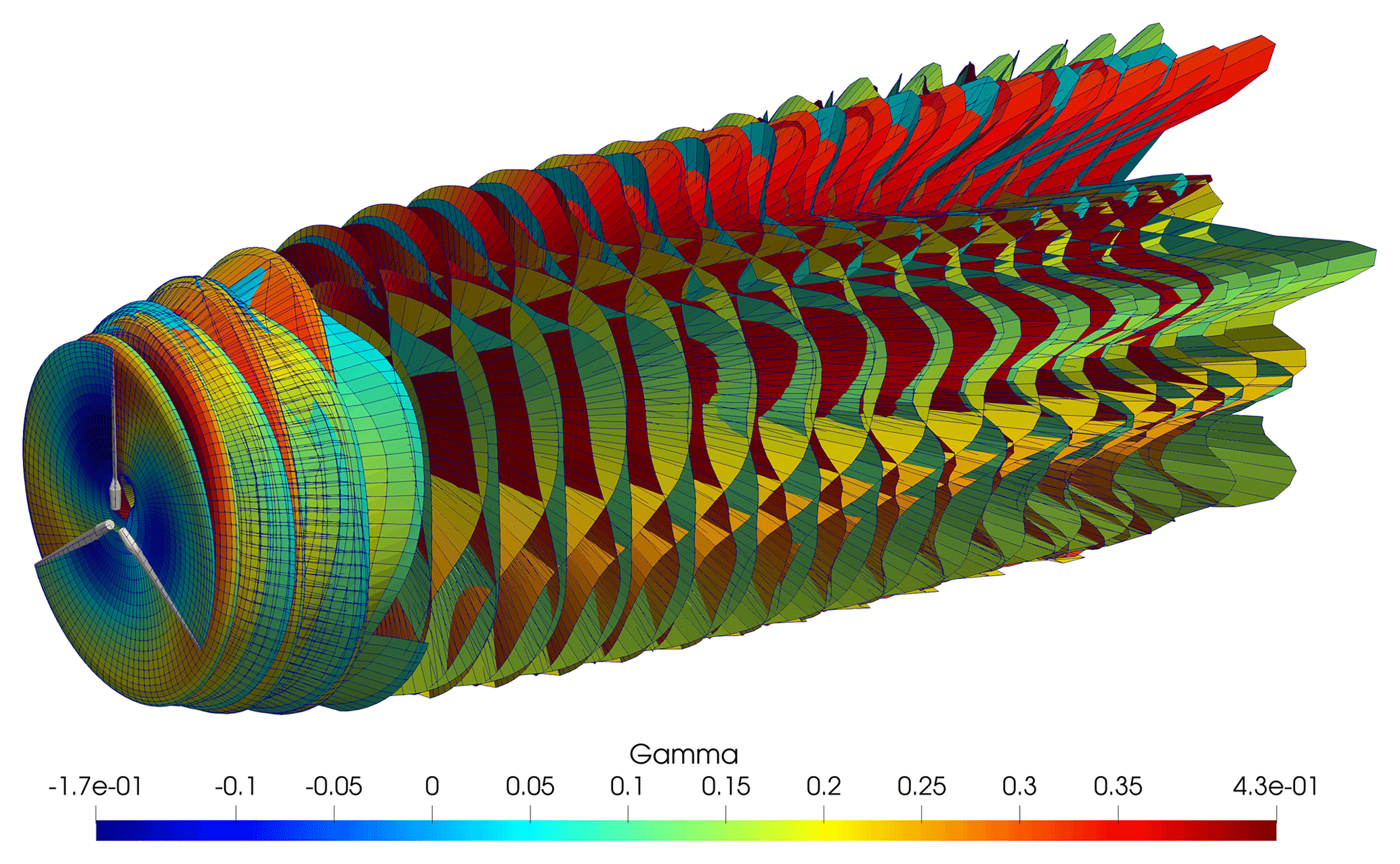
Figure 1Representation of the vortex elements in the wind turbine wake in the LLFVW model. Vortices are colored by circulation values.
2.1.5 Actuator line model
The concept of an ALM for wind turbines was first proposed by Sørensen and Shen (2002) and allows the wind turbine wake to be resolved using Navier–Stokes equations (i.e., computational fluid dynamics – CFD), with limited computational cost with respect to a full CFD solution. The basics of an ALM can be described as follows: the wind turbine blades are divided into a series of blade sections, for which 2D characteristics (Cl, Cd) are determined, as is the case for other “lifting-line”-based approaches such as those described in the previous paragraphs. For each blade section, the relative velocity W is determined by combining the velocity that is sampled from the CFD domain and the structural velocity as . This process is commonly referred to as velocity sampling. In this work, the ALM code developed by coupling OpenFAST to the CFD solver CONVERGE (Richards et al., 2023), CALMA (Converge Actuator Line Model for Aeroelasticity) (Pagamonci et al., 2023), is used. In this code, velocity sampling is handled through the line-average velocity sampling algorithm proposed by Jost et al. (2018). Once the blade forces are computed, they are inserted into the CFD domain as body forces through the force projection procedure. In this work, a piecewise function is used to smear the forces into the domain, as proposed by Xie (2021). The kernel size is a trade-off between numerical stability and accuracy; a kernel size equal to of the chord length is used in the inner 60 % of the blade, while in the outer part of the blade, where chord size is smaller, kernel size is limited by the cell dimension to be 4 times the local cell size. The computational domain is shown in Fig. 2 and matches the dimensions of the Politecnico di Milano (PoliMi) wind tunnel as closely as possible. On the wind tunnel walls, a slip condition is imposed to avoid resolving the wall boundary layer. To account for the latter, the walls are moved inward by a distance equal to the wall boundary layer height, as estimated during preliminary experimental calibration (Bernini et al., 2018). The grid is Cartesian with successive levels of refinement close to the rotor. The base grid size is 0.25 m; in proximity to the rotor the grid size is . In the wake, cell size is , and automatic mesh refinement is used to increase cell size where needed. This approach has been shown to work well and was calibrated with respect to experiments, as in the results presented by Bergua and et al. (2023); it is able to resolve the tip vortex trajectory with accuracy similar to that of comparable numerical techniques (Cioni et al., 2023).

2.2 Test case
The UNAFLOW rotor is an approximately 2.4 m diameter rotor developed by PoliMi during the LifeS50+ project and later used in the UNAFLOW test campaign (Bernini et al., 2018) shown in Fig. 3. The rotor is a 1:75 scale version of the DTU 10 MW rotor (Bak et al., 2013). The blade was redesigned to match the aerodynamic characteristics of the full-scale rotor as closely as possible, with a focus on matching thrust coefficients, as explained in detail in Bayati et al. (2017b, 2016).
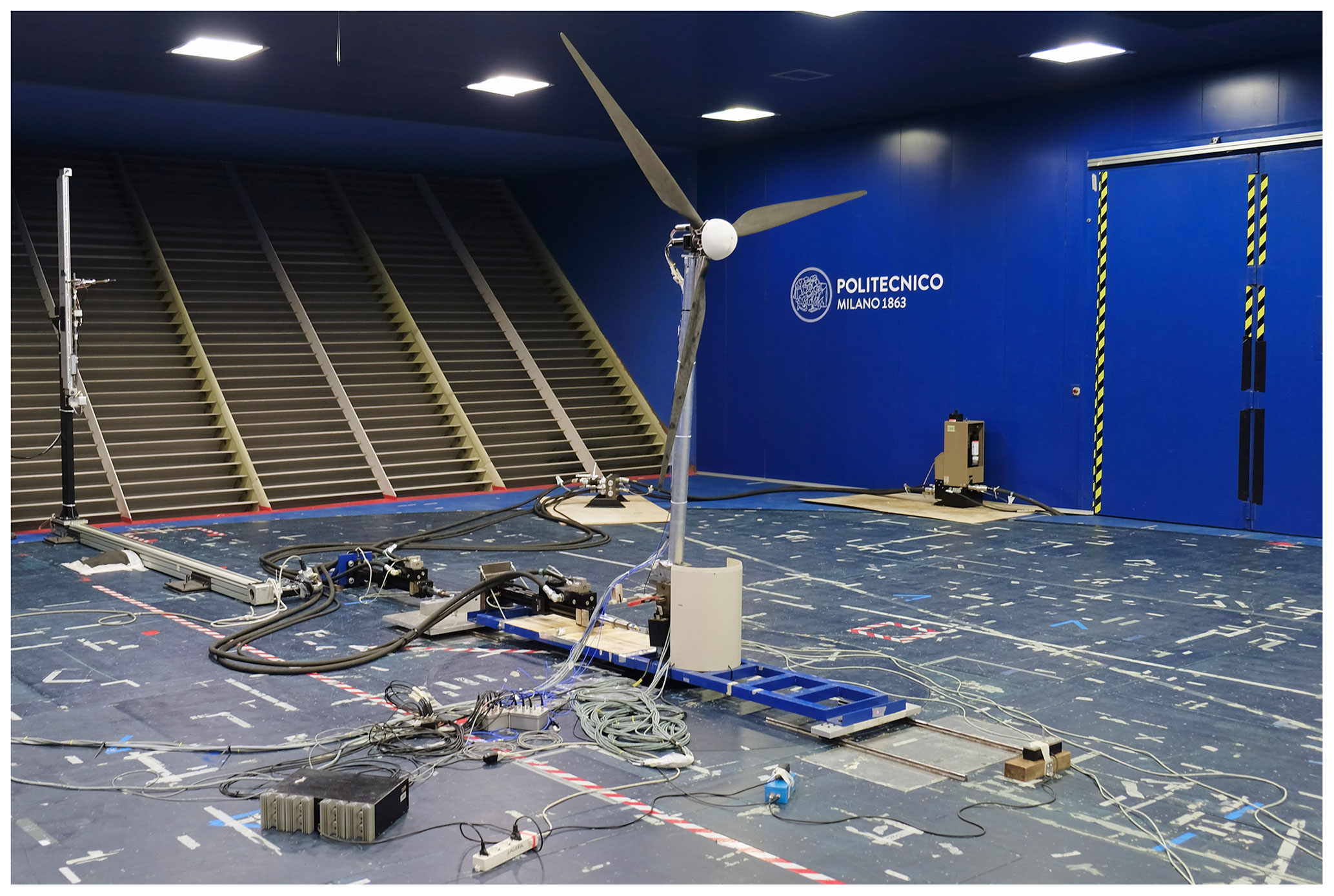
Figure 3UNAFLOW rotor during tests in the wind tunnel. Image courtesy of Politecnico di Milano.
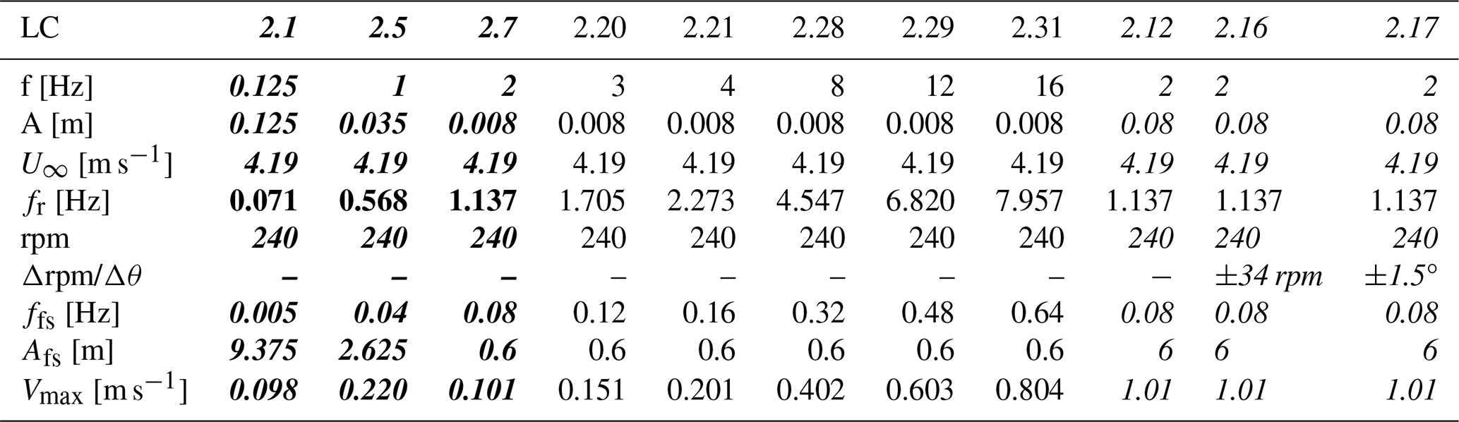
The rotor diameter is geometrically scaled, but a low-Reynolds airfoil was used along the entire blade span and, crucially for this study, the local chord-to-rotor diameter ratio was increased along most of the blade span. The wind speed imposed in the wind tunnel tests is of the full-scale wind speed. During the UNAFLOW test campaign, various oscillatory surge and pitch tests of the rotor were conducted. The amplitudes of the test article's oscillations are scaled geometrically, while the frequency at model scaled is obtained by imposing a constant reduced frequency, defined by Bayati et al. (2017a) as . Results are summarized in the work of Fontanella et al. (2021) and Mancini et al. (2020). The outcomes of the experiments were later made available to the participants of the International Energy Agency Wind Technology Collaboration Programme (IEA Wind) Task 30 (OC6 Phase III) and used for code-to-code comparisons and validation (Bergua et al., 2023). In this work, the data made available to the IEA Wind Task 30 (OC6 Phase III) participants are used as a basis to check the soundness of the numerical results with respect to the experimental baseline. We then build on these test cases and perform forced surge and pitch simulations at frequencies and amplitudes that go beyond what is possible with the PoliMi experimental apparatus. Numerical tests in low wind speeds are also performed to verify model predictions near rotor cut-in wind speed. The load cases (LCs) that are included in this study are summarized in Tables 1 and 2. For each LC, the combinations of frequency, amplitude, wind speed, and rotor speed are shown. In addition, the reduced frequency and full-scale amplitudes and frequencies of the tests are highlighted. To put the tests into context, utility-scale FOWTs (10 MW and above), when mounted on a spar or semi-submersible platform, feature natural frequencies in pitch that are approximately in the range of 0.005–0.05 Hz. Wave excitation is typically in the range of 0.05–5 Hz, with 0.08–0.2 Hz being most common. Tension leg platforms (TLPs), on the other hand, usually feature higher natural frequencies in pitch, roll, and heave, approximately in the 0.5 to 5 Hz range, although amplitudes are typically small.
Table 1Surge load cases (LCs) discussed in this study. Bold text signifies LCs for which experimental measurements are available. Italic text signifies LCs used in OC6 Phase III (Bergua et al., 2023). The operating point corresponds to optimum TSR of 7.5 of the full-scale rotor (DTU 10 MW RWT).
This section is organized as follows: aerodynamic force prediction capability of the aerodynamic theories in nominal operating conditions is discussed first. These conditions correspond to the test cases that were evaluated during the OC6 Phase III project (Bergua et al., 2023), but additional insight is provided herein. Oscillatory pitch tests at cut-in wind speed, where rotor loading is high, are discussed next. Finally, FOWT wake states are discussed.
3.1 Rated wind speed
Rotor thrust normalized by surge amplitude and its phase shift with respect to the surge motion are shown in Fig. 4. Good agreement is noted between the experimental data and the numerical models, and results are in line with those showcased by Bergua et al. during the OC6 Phase III project (Bergua et al., 2023). Interestingly, a linear relationship between normalized amplitude and frequency can be noted for all the numerical models up to 4 Hz. This indicates that the oscillation in thrust force is directly proportional to the relative velocity, as demonstrated in the following. Rotor thrust force can be written as
where Ct is the thrust coefficient, A is the rotor area, and U is the incoming air speed. Assuming a small variation in inflow, the corresponding variation in thrust can be written as
Equation (4) implicitly assumes Ct=const, which is only valid in proximity to the chosen operating point. Assuming a sinusoidal variation in surge , the relative inflow to the rotor can be written as
Therefore, assuming steady inflow, the amplitude of velocity variation is due to the surge variation only and can be written as
If Eq. (6) is substituted into Eq. (4) and divided by the oscillation amplitude, the normalized amplitude is found to be proportional to the oscillation frequency:
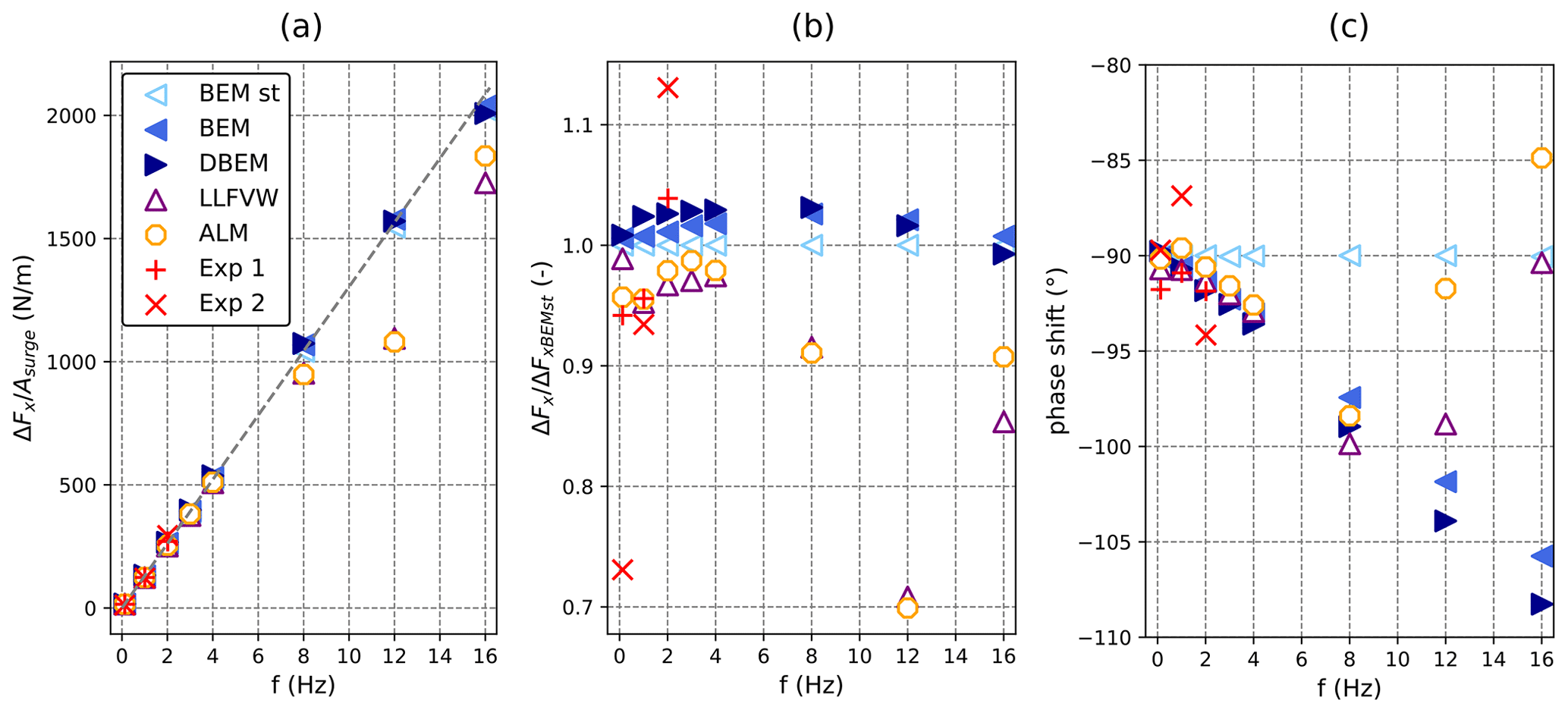
Figure 4Normalized rotor thrust as a function of surge oscillation frequency during tests with harmonic rotor surge motion. (a) Thrust amplitude normalized by surge amplitude, (b) thrust amplitude normalized by quasi-steady model predictions (BEM st), and (c) phase shift of predicted rotor thrust with respect to surge motion. Filled indicators are for models with dynamic polars, and blank indicators are for models with static polars.
Therefore, a linear relationship between normalized amplitude and surge frequency indicates quasi-steady behavior. Deviations from such a trend are an indication of nonlinearities in the analyzed models. It is important to note that deviations from the linear trend can be a result of unsteady aerodynamic effects but also a result of other model nonlinearities such as those present in the lift and drag coefficients. It is also important to keep in mind that the results discussed in the following are valid only for the operating condition that is being analyzed; since the wind turbine is a nonlinear system, the nonlinearities may be more or less evident depending on the specific operating condition. In this context, as shown in Fig. 4, the model analyzed herein behaves quasi-steadily up to 4 Hz, and all the numerical models, including the simple BEM-based ones, are able to correctly predict the thrust variation amplitude. This specific frequency is significant, as it corresponds to an oscillation with a period of 6 s at full scale, which is at the upper range of a typical wave excitation frequency band. Thus, higher-frequency oscillations can hardly be related to linear wave excitation. Although high-frequency oscillation may result from tower deformation, these motions are typically small and are not exclusive of FOWTs. Tension leg platforms could be the exception to this, as these platforms are designed with pitch natural frequencies above the wave excitation range that could be excited by nonlinear forcing, resulting in pitch motion at high frequencies.
On the other hand, the influence of unsteady aerodynamic effects can be seen in the phase shift of the thrust oscillations even when the model behaves linearly. In fact, as shown in Eq. (4), in the absence of unsteady effects, thrust oscillations are expected to be proportional to oscillations in relative velocity. Therefore, in the case of a harmonic surge excitation, rotor thrust is expected to lag behind the surge motion by 90°. The only model that follows the quasi-steady trend is BEM with static polars (BEM st). When unsteady blade aerodynamic effects are included (dynamic polars), the thrust force phase shift is smaller than −90° and thus lags behind the relative velocity, as also noted by Mancini et al. (2020) and Bergua et al. (2023). This behavior can be noted in the BEM and DBEM model trends in Fig. 4c and is also highlighted in the LLFVW model and ALM, despite them using static lift and drag tables. In fact, the phase lag is a consequence of the unsteady vorticity shed from the blade, as first explained by Theodorsen (Leishman, 2016), an effect that both the LLFVW model and ALM are able to explicitly resolve.
Returning focus to the normalized thrust force in Fig. 4a, at 8, 12, and 16 Hz, the LLFVW model and ALM deviate from the linear trend, differently from the BEM-based models, which continue to behave quasi-steadily despite the inclusion of unsteady blade aerodynamics in the BEM model and dynamic inflow models in the DBEM model. These results are consistent with those of Ribeiro et al. (2022, 2023), who found a similar trend in surge simulation of the UNAFLOW rotor using a panel code. These results show how blade-element-based codes, if coupled to a higher-order wake theory, are also able to capture this effect. Ribeiro et al. (2022) attribute the nonlinear ΔFx variations to Theodorsen unsteady attached-flow effects. More recently, in a WESC 2023 presentation, Schulz et al. (2024) attributed the dip in that can be seen at 12 Hz to the returning wake effect, an aerodynamic phenomenon first noted by Loewy (Leishman, 2016). This effect is an extension to Theodorsen's theory that typically manifests in rotors and consists of nonlinear variations in aerodynamic forces on a plunging blade due to interaction with the vorticity shed, not only by the blade in examination, but also by the other rotor blades and the returning wake of the blade itself. In the current test case, this effect is most noticeable when the surge frequency is 12 Hz, as this corresponds to 3 times the revolution frequency, i.e., , where the effects of the shed vorticity from the three rotor blades are in sync (Leishman, 2016). In fact, when increasing the oscillation frequency even further to 16 Hz, ALM and LLFVW continue to deviate from the linear frequency-normalized amplitude trend (Fig. 14a), although to a lesser extent in relative terms (Fig. 14b). BEM models, on the other hand, are unable to capture the returning wake effect, as they do not include the mutual interaction of shed vorticity from other rotor blades and do not show the dip in that the higher-order models manifest. These unsteady effects may be larger in a scaled-model test case, as they grow larger as airfoil reduced frequency () grows larger, and chord lengths are typically increased in scaled models to increase rotor thrust at low Reynolds numbers.
It is also important to note that dynamic effects may be more important in the case of larger rotors. This may be due to several factors. Firstly, as explained in Sect. 2.2, the model tests presented herein are scaled based on reduced frequency (Bayati et al., 2017a), which depends on rotor diameter, disproportionally affecting larger rotors. Therefore, assuming that reduced-frequency scaling is relevant for aerodynamic unsteady effects, these may occur at lower full-scale frequencies on larger rotors, such as on 15+ MW turbines. This is compounded in the context of returning wake effects, as larger rotors also feature lower rotational speeds. Finally, some platform concepts, such as tension leg platforms, typically feature pitch natural frequencies in the 0.2–0.25 Hz range (Matha, 2009), above ordinary wave excitation. Phenomena such as nonlinear wave forcing or 3P aerodynamic forcing could excite these resonance modes and induce oscillations and unsteady aerodynamic effects. Further research is needed to fully understand the implications of these phenomena.
At lower oscillation frequencies, differences in the aerodynamic forces predicted by the different wake models can be seen if harmonic oscillations in blade pitch and rotor speed are introduced with the surge oscillation. Results from 2 Hz frequency tests are shown in Fig. 5. When an oscillation in rotor speed is introduced (LC 2.16), wake dynamics cause an increase in the aerodynamic thrust amplitude, while when a blade pitch oscillation is introduced (LC 2.17), aerodynamic thrust amplitude is lower for the LLFVW and DBEM models. On the other hand, very little difference in rotor thrust amplitude is noted in LC 2.12, where the same thrust oscillation as LCs 2.16 and 2.17 is imposed, but no blade pitch or rotor speed oscillation is present. The different behavior of the numerical models in LC 2.12, where no dynamic inflow effects are apparent in the thrust force amplitude with respect to LCs 2.16 and 2.17, is hard to explain given that axial induction along the blade span, a metric directly related to the “intensity” of the wake, varies to a similar degree in all three test cases (Fig. 6). Moreover, Fig. 6 highlights how in absolute terms, axial induction reaches higher values in LC 2.12. In this load case, axial induction is greater than the threshold of 0.4 in the outer 15 % of the blade, where momentum theory is invalid and specific high-induction corrections are applied to BEM-based solutions in AeroDyn. Moreover, while these results are in line with results from participants of the OC6 Phase III numerical experiment (Bergua et al., 2023), the lower amplitude of the thrust force predicted by the dynamic models compared to the quasi-steady approaches in the case of a blade pitch oscillation appears counterintuitive because overshoots or undershoots in rotor forces with respect to quasi-steady wake theories are noted in the case of blade pitch step tests (Øye, 1991).
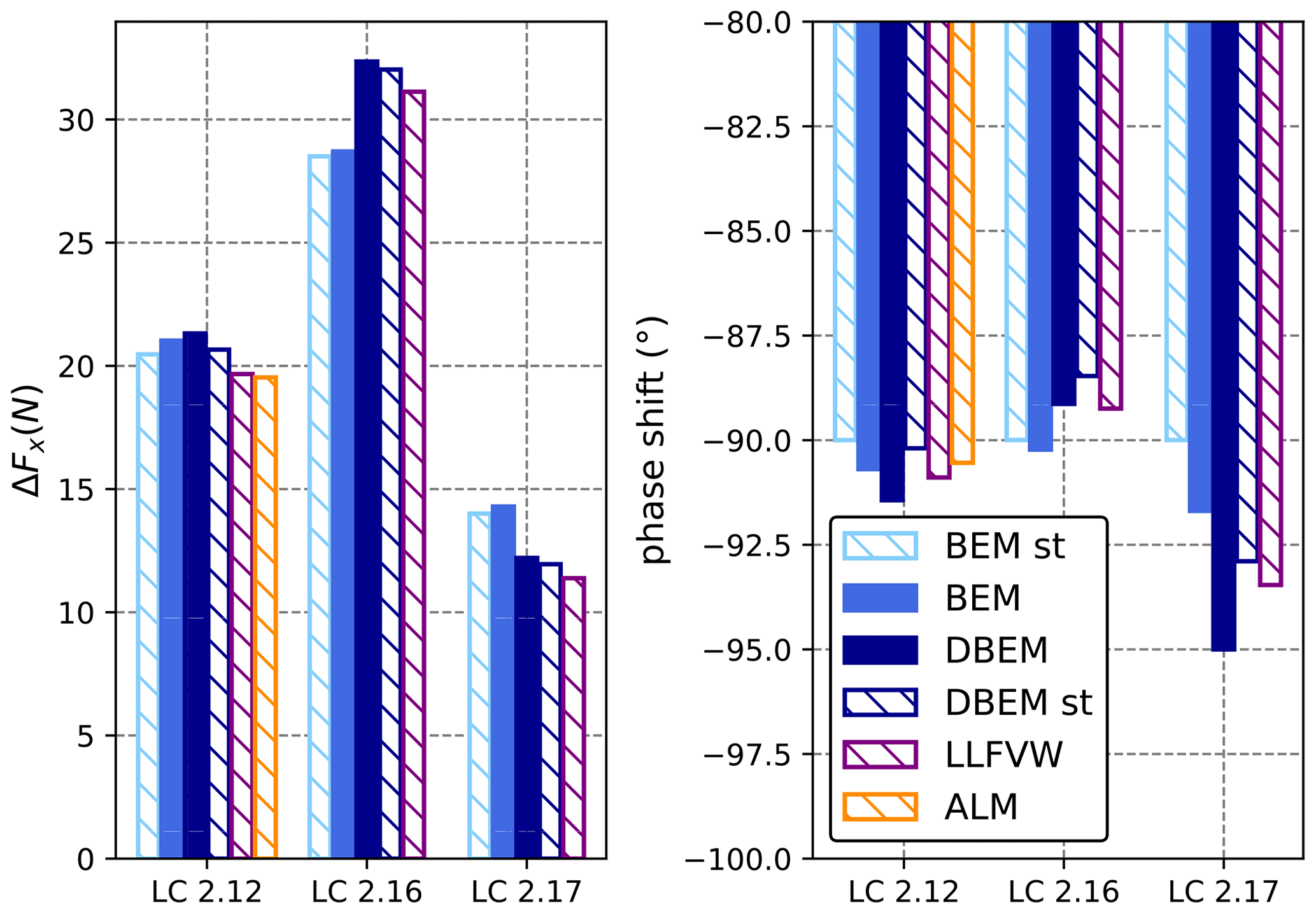
Figure 5Amplitude and phase shift of rotor force under 2 Hz harmonic surge motion (LC 2.12), harmonic surge motion and rotor speed variation (LC 2.16), and harmonic surge motion and blade pitch variation (LC 2.17). Filled bars represent models with dynamic polars, and banded bars represent models with static polars.
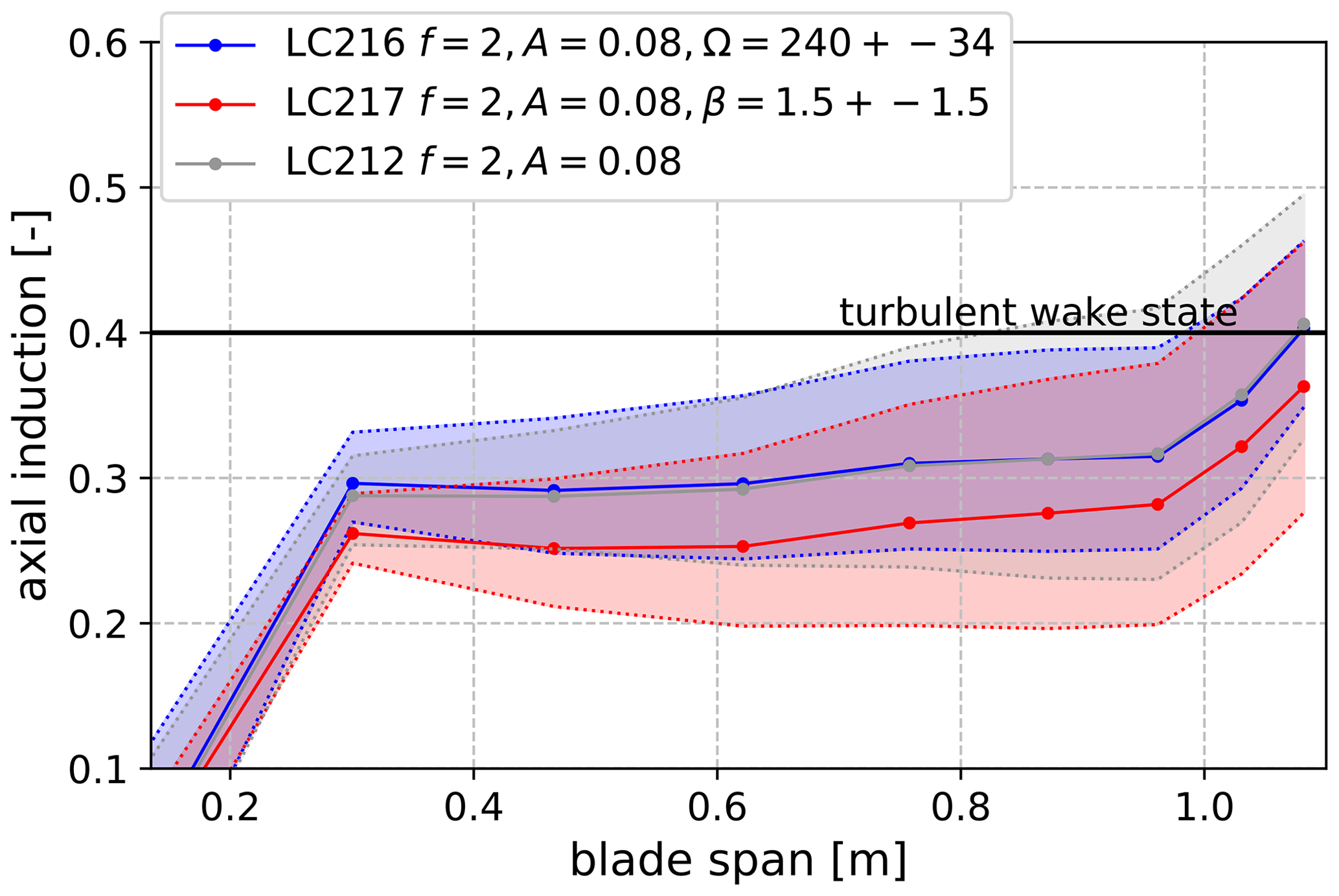
Figure 6Mean (lines) and variation range (shaded areas) of axial induction as a function of blade span for Blade 1 for the LLFVW model. Axial induction is computed through Eq. (15) during post-processing.
However, wake dynamics in the case of oscillatory tests such as those shown in LCs 2.12, 2.16, and 2.17 are arguably different from those occurring during a step test. To illustrate this, step tests in surge velocity, blade pitch, and rotor speed for the UNAFLOW rotor are shown in Figs. 7 and 8. In a step test, a rapid “step-like” change in operating conditions is imposed. Step tests are often used to evaluate the dynamic response of a rotor to a sudden change in operating conditions. In the step tests performed in this study, the rotor is operating at rated conditions, with a wind speed of 4.19 m s−1. The magnitudes of the blade pitch, rotor speed, and surge velocity steps are the same as the amplitude of the oscillations imposed in LCs 2.12, 2.16, and 2.17. Therefore, the magnitude of the step changes is 2 m s−1 for surge velocity (as in LCs 2.12, 2.16 and 2.17), 3° for blade pitch (as in LC 2.17), and 72 rpm step for rotor speed (as in LC 2.16). The duration of the steps is 0.2 s, which corresponds to half a cycle in the case of the LCs analyzed in Fig. 5.

Figure 7Blade pitch and rotor surge step tests computed using LLFVW. From (a) to (d): wind speed, blade pitch, axial-induced velocity at 88 % blade span, and thrust force normalized by starting rotor thrust.
As shown in Fig. 7, in the case of a simple surge velocity step, there is very little aerodynamic load undershoot or overshoot. This phenomenon was also noted by other authors (Schepers, 2022; Corniglion et al., 2022), who found little variation in induced velocity despite significant variations in axial induction. In particular, Corniglion et al. (2022) ran similar analyses on the UNAFLOW rotor and attributed the lack of dynamic load overshoot or undershoot to the fact that the step change in surge velocity causes the blade tip vortex spacing in the near wake to vary, partially compensating for the induction change along the blade. The magnitude of this cancellation effect depends on the rotor design and on the operating point under consideration. The dynamic inflow effect, as noted and described by Snel and Schepers (1995), can be noted in the case of a blade pitch step, with rotor thrust taking up to 2 s to reach a steady-state value. A step change in rotor speed is also simulated with the ALM, and the resulting change in rotor thrust is shown in red in Figs. 7 and 8. In both cases, ALM, which is able to solve the real physics and inertia of the wake through Navier–Stokes equations, predicts slightly higher thrust variations and slightly lower thrust overshoot than LLFVW. Rotor thrust, however, takes a similar time to reach a steady-state value. Therefore, the LLFVW model is considered accurate for the intended purpose of this specific analysis, which is to observe the timescales of the rotor aerodynamic response and to understand the underlying phenomena involved. Interestingly, this effect is also present when concurrent blade pitch and surge velocity steps are introduced.
Similar considerations can be drawn in the case of a rotor speed step test: dynamic load overshoot or undershoot can be observed in the case of a rotor speed step and can also be noted when rotor speed and surge velocity steps are combined, despite this dynamic effect being present to a much smaller extent in the case of a surge velocity step. It must be noted that step-like changes in rotor speed arguably become less likely as turbine sizes increase and increases in rotor inertia outweigh those in aerodynamic torque. Nonetheless, such a case is considered in this study from a conceptual point of view to evaluate the effects on aerodynamic forces of changes in rotor speed and platform surge combined.
Induced velocity time series in the outer part of the blade are also shown in Figs. 7 and 8. In line with previous scientific literature, during both rotor speed and blade pitch steps, variations in induced velocity are much greater than those recorded during a surge velocity step. This consideration holds true for the outer 50 % of the blade, which generates the majority of the axial loading in the selected operating conditions. These results are not shown here for brevity and to avoid overlap with the work of Corniglion et al. (2022), to which the reader is referred for further considerations.

Figure 8Rotor speed and rotor surge step tests computed using LLFVW. From (a) to (d): wind speed, rotor speed, axial-induced velocity at 88 % blade span, and thrust force normalized by starting rotor thrust.
The timescales of the dynamic wake effect for this rotor at rated operating conditions can also be deduced from the data shown in Figs. 7 and 8, as thrust force requires 1–2 s to reach its steady-state value. In the case of the oscillatory load cases examined in this study, an entire cycle lasts 0.5 s. Therefore, while wake physics remain the same, we argue that a different dynamic effect is being observed herein and that a straightforward load overshoot when dynamic inflow effects are accounted for cannot be expected. In this context, the fact that the simple dynamic wake model integrated in the tested DBEM model is able to improve agreement in the prediction of aerodynamic force amplitude for an oscillatory test is a good indication that the model is able to capture the general physics of the dynamic wake problem at hand. This is indeed very different from a step test in rotor speed or blade pitch for which such dynamic wake models were developed and tuned.
For more insight on how dynamic wake effects influence aerodynamic forces, the spanwise amplitude and phase shifts of axial-induced velocity and relative axial velocity recorded during LCs 2.12, 2.16, and 2.17 are shown in Fig. 9. Focus is placed on these parameters, as they strongly influence thrust force variations. In fact, the spanwise thrust force per unit span of each blade can be written according to blade element theory as
where α is the local angle of attach , ϑ is the blade pitch angle, φ is the local twist angle, and Cax is the axial force coefficient. The relative velocity can be decomposed into axial and tangential components, as radial components do not generate aerodynamic loading in blade-element-based models:
The axial and tangential velocity components can be written as the sum of incoming wind speed, the induced velocity, and the structural velocity (Eq. 10):
Considering that the structural velocity is the same for all the compared wake models, as the tower and blades are rigid in the numerical models, that the wind speed is aligned with the rotor (U∞Y=0), and in the hypothesis that tangential induced velocity is small (UindY≅0), UrelY can be considered to be independent from the wake model, and focus can be put on axial relative velocity UrelX only, which directly influences aerodynamic thrust (Eq. 8).
In Fig. 9, the spanwise amplitude and phase shift with respect to the imposed surge motion of the relative blade axial velocity are shown in the bottom two rows. In the top rows, the phase shift with respect to the imposed surge motion and variation amplitude as a function of blade span of the induced velocity are shown. The columns correspond to LCs 2.12, 2.16, and 2.17. If the spanwise amplitudes of induced velocity variation for the three load cases are compared to each other in Fig. 9b, f, and l, similar ΔUindX can be noted for all three LCs. This indicates that the different model behavior observed in the three LCs – i.e., lack of differences between dynamic wake models and quasi-steady ones in LC 2.12 but different thrust force amplitudes for models with and without dynamic wake in LC 2.16 and 2.17 – is not caused by lower variation in UindX, as is the case for step tests (Figs. 7 and 8). Focusing on LC 2.12 with respect to the BEM model, which does not include wake dynamics, the DBEM model, the LLFVW model, and ALM show significant differences in relative velocity. All three models predict lower relative velocity oscillations in the outer span of the blade but higher oscillations in the inner part, leading to the differences between them canceling out when the global rotor thrust is considered. Given that the structural windward velocity and the wind speed are the same for all the blade stations and all numerical models, as surge motion is being analyzed, this phenomenon is a result of differences in induced velocity. In this regard, the induced velocity amplitude along the blade span is lower on the entire blade for the models that include dynamic induction. This is consistent in all three LCs analyzed in Fig. 9. The lower variations in induced velocity lead to higher or lower relative velocity amplitudes, depending on how the former combine with oscillations in structural velocity (Eq. 10). To this end, it is useful to focus on the phase shift of the induced velocity (Fig. 9a, e, i). Focusing on BEM results, which do not include phase lags and are thus easier to interpret, the phase shift of the induced velocity shifts from −90° in the outer part of the blade to +90° in the inner part of the blade. On the other hand, the structural velocity lags behind surge motion and is thus shifted −90° for all blade stations.
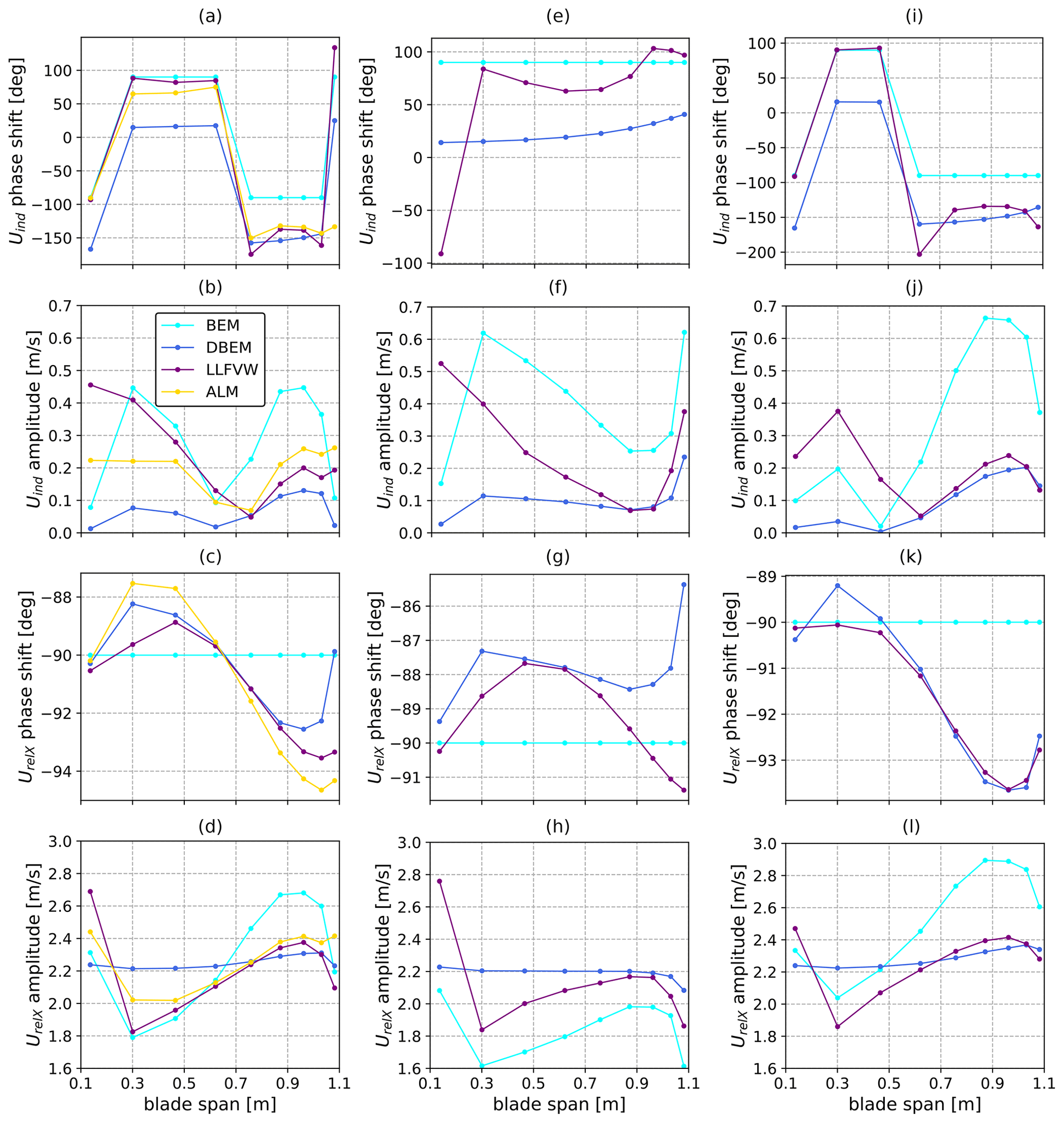
Figure 9Phase shift (top) and amplitude (middle) of induced velocity and amplitude of relative velocity (bottom). (a–d) LC 2.12, (e–h) LC 2.16 – harmonic rotor speed variation, and (i–l) LC 2.17 – harmonic blade pitch variation.
Therefore, if induced velocity and structural velocity variations are in phase, their combination increases the variation in axial velocity, whereas if the phase shift of the induced velocity is +90°, the two signals are in phase opposition, and thus their combination leads to lower relative velocity. Therefore, in the case of LC 2.12, this phenomenon has the effect of augmenting the velocity oscillations in the outer part of the blade and diminishing them in the inner part. Despite the models that include wake dynamics having different phase shifts, this reasoning can be applied to the latter models as well. Therefore, because the models that account for dynamic induction have lower induced velocity amplitudes, they show lower variations in induced velocity in the outer part of the blade and higher ones in the inner part with respect to BEM. The way structural and induced velocity variations combine is also the reason differences between the numerical models emerge in LC 2.16 (Fig. 9e–h) and 2.17 (Fig. 9i–l). Similar to LC 2.12, the wake dynamics act like a filter and reduce the amplitude of the induced velocity variations along the span. In LC 2.16, because the phase shift of UindX is positive, more variation in relative velocity for DBEM and LLFVW can be noted. On the other hand, because the UindX phase shift is negative along most of the blade span in LC 2.17 (Fig. 8i), variations in induced velocity are in phase with the structural velocity, leading to less induced velocity variation and less aerodynamic thrust variation in DBEM and LLFVW.
Finally, it is interesting to investigate why the UindX phase shift may assume positive or negative values depending on the spanwise location and test case. These can be explained by considering the induced velocity as
where a is the induction factor for each radial station. In the case of more advanced theories such as LLFVW and ALM, where a is not computed through a momentum balance, this factor is used to summarize the effect of the wake on each radial station. It is clear from Eq. (11) that variations in UindX are a result of the combined variations of UstrX and a. For the UNAFLOW rotor, the two quantities combine in different ways along the span, leading to the observed behavior in LC 2.12. In summary, dynamic wake effects act like a filter on the induced velocity and reduce its variation in all three LCs: 2.12, 2.16, and 2.17. In the case of simple surge motion (LC 2.12), no dynamic inflow effects on the loads are observed because this effect leads to higher load amplitudes in the outer part of the blade that are compensated for by lower amplitudes in the inner part.
3.2 Cut-in wind speed
BEM-based models need to perform reliably in even more challenging conditions than those examined in Sect. 3.1, despite tests carried out in this section highlighting some differences between the aerodynamic theories. In fact, as discussed in Sect. 2, BEM models are challenged when rotor loading is high and specific high-induction empirical corrections need to be employed. In this view, rotor loading generated from the combination of surge oscillation and inflow conditions tested in Sect. 3.1 does not push BEM models to their limit (Fig. 6). On the other hand, at lower wind speeds, modern wind turbine rotors are typically highly loaded, thus motivating the examination of these conditions. Moreover, we argue that rotor–wake interaction is most likely in these operating conditions for a floating rotor. In fact, interaction of the rotor with its own wake, as in the rotor blades moving in and out of their own wake, is most likely when the following holds.
-
Downstream wake convection velocity is low. This can be achieved through a combination of low incoming wind speed and high rotor loading, which leads to high axial induction and thus lower velocity downstream of the rotor plane.
-
Fore–aft rotor velocity of the blade elements is high. In the case of harmonic oscillatory tests such as the ones performed herein, this can be achieved through a combination of high amplitude and high frequency of the oscillations.
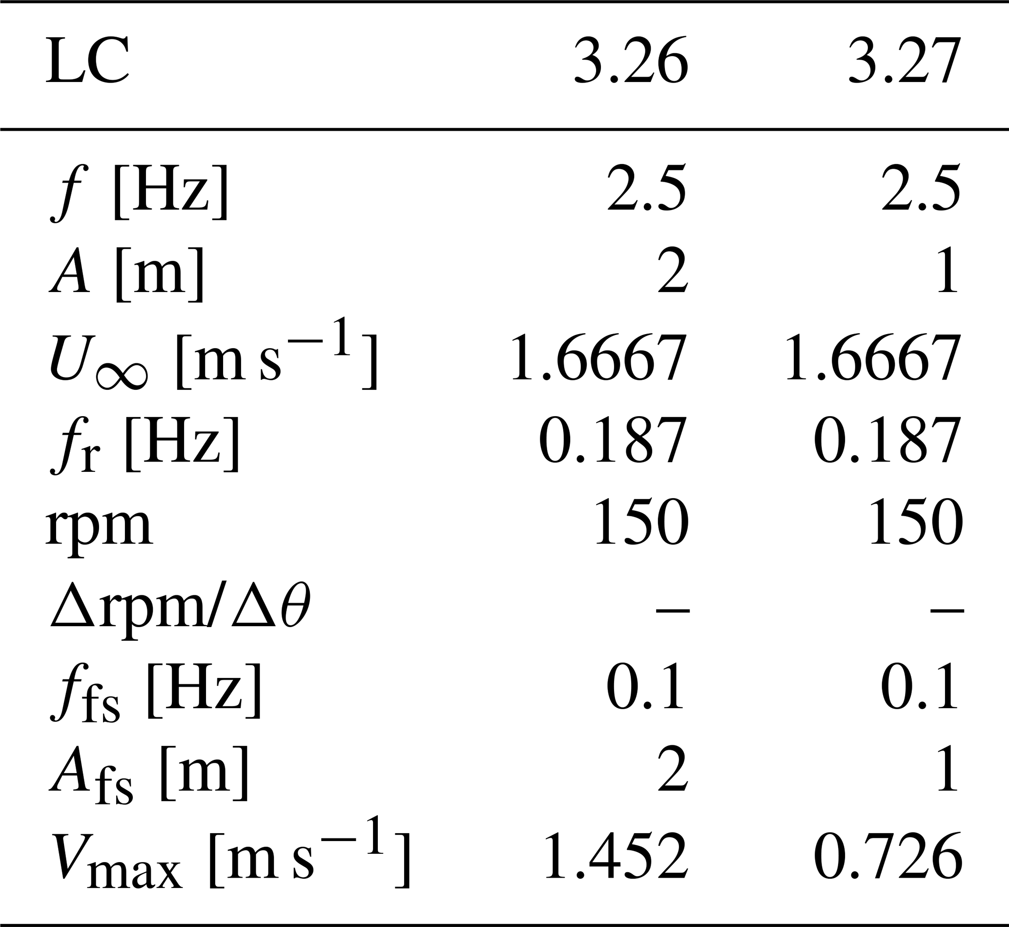
Based on these considerations, two additional LCs are evaluated, namely LC 3.26 and 3.27, as shown in Table 2. In these LCs, the turbine is operating at a full-scale wind speed of 5 m s−1, close to the cut-in wind speed. In these inflow conditions, many variable-speed rotors, including the DTU 10 MW upon which the UNAFLOW rotor is based, operate at minimum rotor speed (to avoid tower resonance) and are forced to run at a high tip-speed ratio. This leads to high rotor loading, which when combined with the low incoming wind speed meets the criteria highlighted in point (1). The tests are performed with a forced floater pitch oscillation of 1 and 2° at a full-scale equivalent frequency of 0.1 Hz, which is commonly in the wave excitation range. A floater pitch oscillation is favored over a surge oscillation, as the former can leverage the full turbine height, inducing larger fore–aft oscillations in the upper part of the rotor. As shown in the following sections, these conditions indeed lead to rotor–wake interaction in the selected test case. These imposed oscillations in the model-scale test case treated herein can be put into context and compared to wave conditions that would lead to similar fore–aft velocities on full-scale research FOWTs. The maximum blade tip fore–aft velocity induced by a pitch oscillation, when the blade is pointing upwards, can be written as
where ltwr and lbld are the tower and blade lengths, and A and f are the amplitude and frequency of the harmonic oscillation. The center of rotation is assumed to correspond, as a first approximation, to the center of floatation of the system. Although the position of the center of rotation is influenced by many factors, such as external forcing and the position of the center of gravity and center of buoyancy, this decision is supported by recent research (Patryniak et al., 2023), indicating a strong alignment between the center of rotation and the center of floatation, particularly evident under higher wave excitation frequencies. By inverting Eq. (12), the required oscillation amplitude to reach an equivalent Vtip can be expressed as
Finally, the height of a regular wave required to reach an oscillation with amplitude A(f) can be expressed as
Since response amplitude operators (RAOs) typically relate two-sided wave heights to two-sided oscillation amplitudes, the required amplitude is doubled. The resulting wave heights derived for common research turbines are shown in Fig. 10 for pitch oscillations (a) and surge oscillations (b), in which case Eq. (12) is replaced by Vtip=2πfA. RAOs are extracted from the plots in Ramachandran et al. (2013) for the NREL 5 MW OC3 model and from Papi and Bianchini (2022) for the NREL 5 MW OC4 and IEA 15 MW models.
Table 3Dimensional characteristics of floating reference turbines.

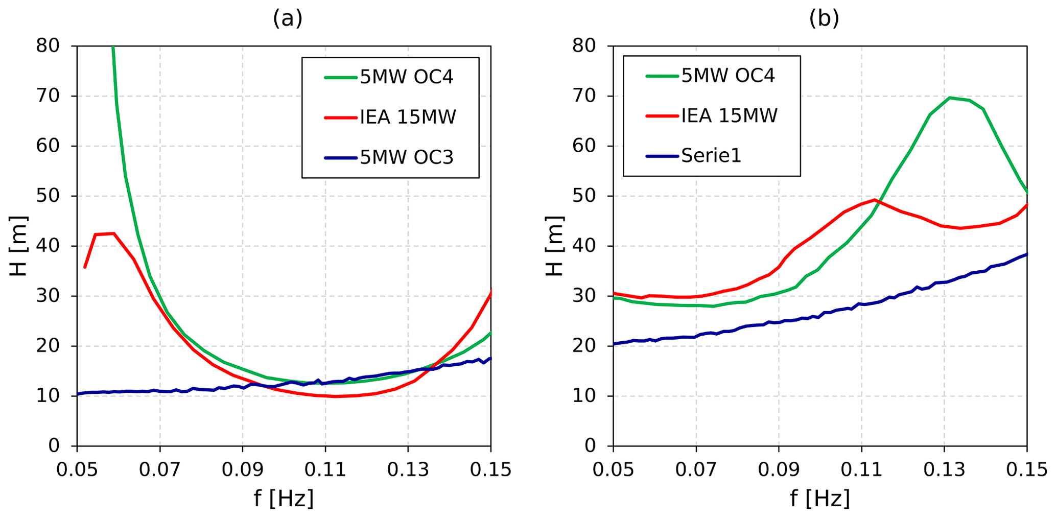
Figure 10Required two-sided wave height for blade tip velocity to reach value reached in LC 3.26 (4.357 m s−1 at full scale) through (a) pitch motion and (b) surge motion.
When Fig. 10a and b are compared, as expected, much higher wave heights are required to reach the specified fore–aft velocity in the case of surge motion. Focusing on pitch motion (Fig. 10a), wave heights of approximately 10 to 13 m are required between 0.09 and 0.13 Hz to reach a rotor apex fore–aft velocity equivalent to LC 3.26 at full scale. Such large waves in low-wind-speed conditions are uncommon, but not unrealistic. For example, recent studies have suggested that extreme 50-year wave heights of approximately 8.5 m are possible at 5 m s−1 wind speed at a site with severe met-ocean conditions, as demonstrated by the environmental contours shown in Papi et al. (2022). Nonetheless, LC 3.26 is considered to be an extreme case in this study. If we consider LC 3.27, where oscillation amplitude is halved, half the wave height is required due to the linear nature of RAOs.
The predicted amplitude and phase shift of rotor thrust in these conditions (LCs 3.26 and 3.27) are shown in Fig. 11. The thrust force oscillations are again summarized by reporting oscillation amplitude and phase shift values, as the imposed oscillations cause variations in aerodynamic forces mostly at the oscillation frequency itself. Significant underprediction of thrust force oscillation can be noted for the BEM model. On the other hand, DBEM, LLFVW, and ALM are all very close in magnitude, indicating that, once again, a medium-fidelity aerodynamic theory such as LLFVW is very close to a high-fidelity wake model such as ALM in the prediction of rotor forces and that the dynamic inflow model implemented in DBEM performs well in the prediction of global rotor loads in these conditions. In contrast to LCs 2.12, 2.16, and 2.17 (Fig. 5), significant differences in both amplitude and phase shift can be seen when dynamic polars are used rather than static ones.
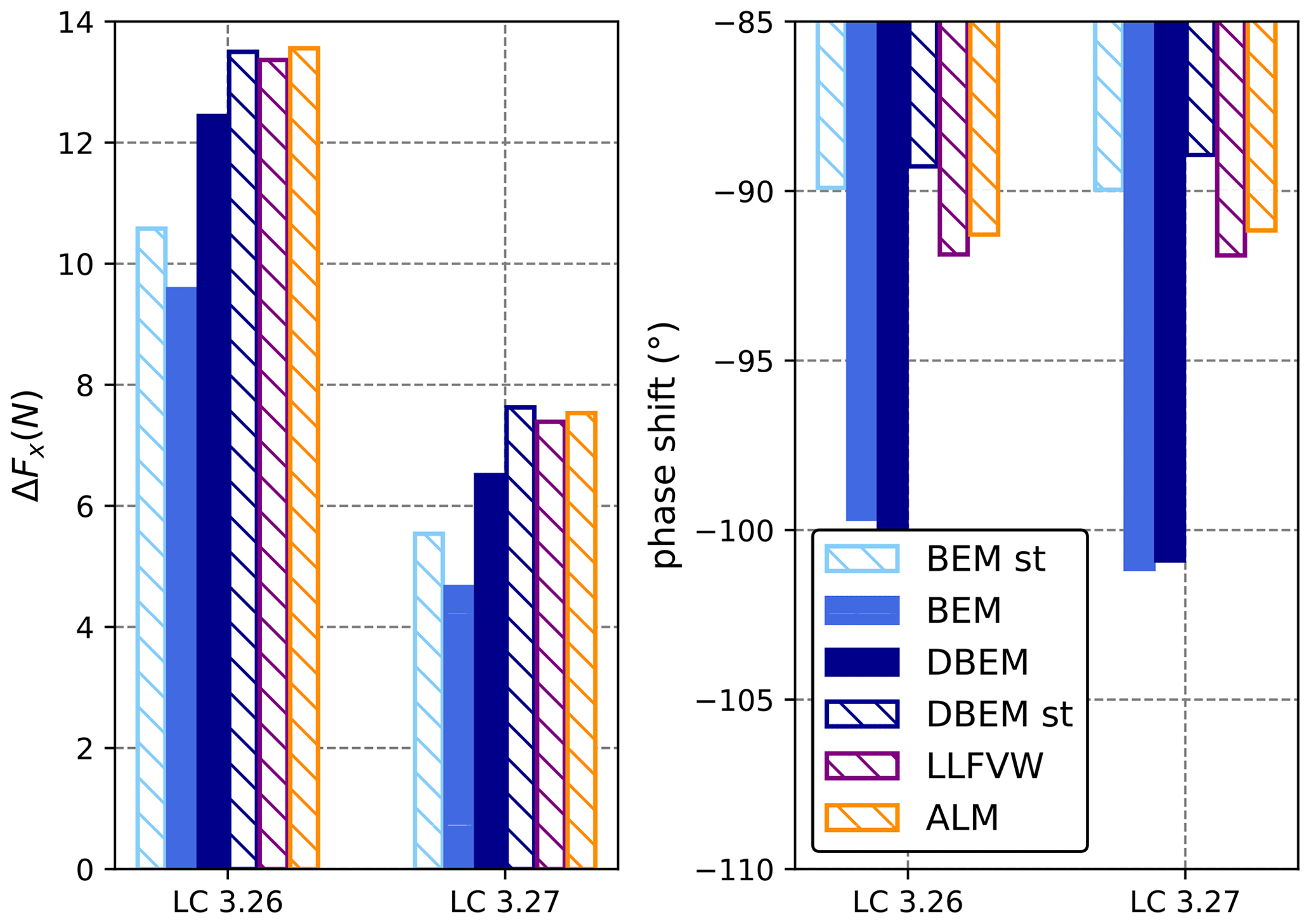
Figure 11Amplitude and phase shift of thrust force at cut-in wind conditions. Filled bars represent models with dynamic polars, and banded bars represent models with static polars.
To investigate this in more detail, spanwise distributions of axial induction, relative axial velocity, and out-of-plane aerodynamic force per unit length in LC 3.26 are shown in Fig. 12. Spanwise distributions are shown for Blades 1 and 2 because the revolution frequency is synchronized with the oscillation frequency. Therefore, as pitch motion introduces asymmetric axial velocity distributions, spanwise quantities are different on the three blades. On both blades shown in Fig. 12a and b, axial induction exceeds the value of 0.4, where momentum theory is considered invalid. Moreover, axial induction reaches values above unity in the outer 60 % of the blade span for the LLFVW model and ALM on Blade 1 (Fig. 12b).
In the LLFVW model and ALM, which do not explicitly solve for axial induction, this parameter is computed in a post-processing phase by rearranging Eq. (1) as
As discussed in Sect. 2, AeroDyn includes structural velocity in the momentum side and in the blade element side of the momentum balance and is consistent with Eq. (15). A direct consequence of this is that induction factors above unity are directly linked to flow reversal on the rotor blades. This can be noted by comparing Fig. 12a and c, where negative inflow on the blades can be seen in the outer 40 % of Blade 1 where axial induction is above unity for LLFVW and ALM. Figure 12c also confirms that rotor–wake interaction, as hypothesized in Sect. 3.2, does indeed occur in LC 3.26. However, as shown in Fig. 12d, no flow reversal occurs on Blade 2. Analogous considerations can be drawn for Blade 3, which is not shown for brevity. Flow reversal can especially be noted in the LLFVW model and ALM in Fig. 12c, which also reach the highest axial induction values (Fig. 12a). Negative relative inflow near the tip of Blade 1 is also predicted by DBEM, although to a lesser extent (Fig. 12c). On the other hand, BEM does not predict flow reversal on the rotor (Fig. 12c), and axial induction values always remain below unity (Fig. 12a). Spanwise axial force per unit length along Blades 1 and 2 is compared in Fig. 12e and f. Analogous to the relative velocity, DBEM is able to improve the prediction of the variation amplitude of axial force along the span for Blade 2. It also improves predictions with respect to BEM on Blade 1, but only in the inner 60 % of the span. Indeed, DBEM's dynamic induction correction brings this model's results more in line with higher-order theories in the inner part of the blade, where induction factors are lower, but fails to do so in the outer part (Fig. 12b). Despite this, the combination of aerodynamic force variation on the three blades leads to thrust force oscillations very similar to higher-order theories, as shown in Fig. 11, once more proving the viability of BEM models as an industrial tool. However, the differences noted in the spanwise quantities on Blade 1 in BEM and DBEM compared to higher-order theories (Fig. 12c, e) indicate limitations. In fact, because AeroDyn treats structural velocities as apparent wind, flow reversal on the rotor is directly related to VRS. As will be shown in Sect. 3.3, this assumption is incorrect, and despite flow reversal, we argue that the rotor does not enter VRS in LC 3.26. However, because VRS is erroneously detected in BEM and DBEM, AeroDyn switches to using an empirical correction, which is incorrect. Therefore, for scenarios like LC 3.26, the limitations of treating structural velocities as apparent wind and neglecting additional inertial effects in BEM are apparent, especially when handling reverse flow situations on the rotor. Moreover, the oscillation frequency in LC 3.26 is high with respect to the flow time constant, and thus interaction with the induced velocity gradient in the axial direction may also be relevant (de Vaal et al., 2012). Tests similar to these could help further improve and advance BEM models.
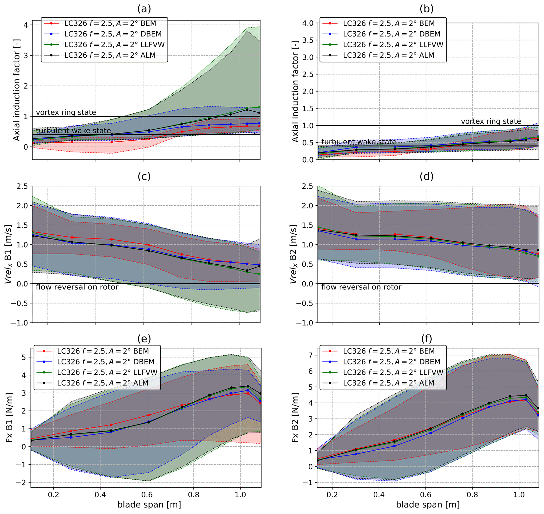
Figure 12Mean (lines) and variation range (shaded areas) of axial induction as a function of blade span for (a) Blade 1 and (b) Blade 2, relative axial velocity along blade span for (c) Blade 1 and (d) Blade 2, and axial force per unit length along blade span for (e) Blade 1 and (f) Blade 2. Values computed using the LLFVW model.
3.3 Wake states
Axial induction values are often linked to the wake state the rotor is operating in. In particular, axial induction values above unity conventionally indicate that the rotor is operating in vortex ring state (VRS), while values between 0.4 and 1 are linked to the turbulent wake state (TWS). In both cases, momentum theory is invalid, and specific empirical models are typically applied in BEM-based codes. Moreover, many codes use axial induction as a threshold to switch between submodels that have been developed over time to model specific conditions such as TWS or VRS. For instance, this is the case for AeroDyn (Ning et al., 2015) and TNO's code AeroModule (Mancini et al., 2022), despite both codes not explicitly solving for axial induction. We argue that, from a theoretical standpoint, such a direct link between axial induction and wake state can only be assumed in the case of a static rotor operating in steady-state inflow conditions, where the momentum balance is applied in an inertial reference frame. In the case of a floating rotor, the high-induction factors observed in Fig. 12a are simply a consequence of the momentum balance being applied in a non-inertial frame and are due to the unsteady rotor-relative velocities. To demonstrate this point, the axial velocity field in the rotor wake during LC 3.26 shown in Fig. 13 can be observed. The velocity in the rotor reference frame is derived as follows: the structural velocity in the axial direction due to pitch motion can be written as
where ϕ is the geometric angle deriving from the combination of rotor overhang and height above the oscillation point, R is the distance from the oscillation center, Rz is the height, Rx the rotor overhang, Vt(t) is the rotational velocity due to pitch motion, and θ(t) is the instantaneous pitch angle:
With the structural velocity defined as in Eq. (16), this component can be subtracted from the velocity field to obtain the axial flow velocity in the rotor reference frame. The result of this operation is shown in Fig. 13 for LC 3.26. For each time instant, the axial velocity in the fixed inertial reference frame is shown on the left, while the axial velocity in the rotor reference frame is shown on the right. Large degrees of flow reversal in the upper part of the flow field can be seen in the relative reference frame. However, in the absolute frame, no such reversal occurs. Significant degrees of wake expansion can be seen, indicating that the turbine is likely operating in TWS, a condition that is compatible with the high mean rotor loading of this operating point. Despite this, in the static reference frame, the wake appears to be in line with typical wind turbine wakes, and flow structures typical of VRS or propeller brake state (PBS) cannot be observed.
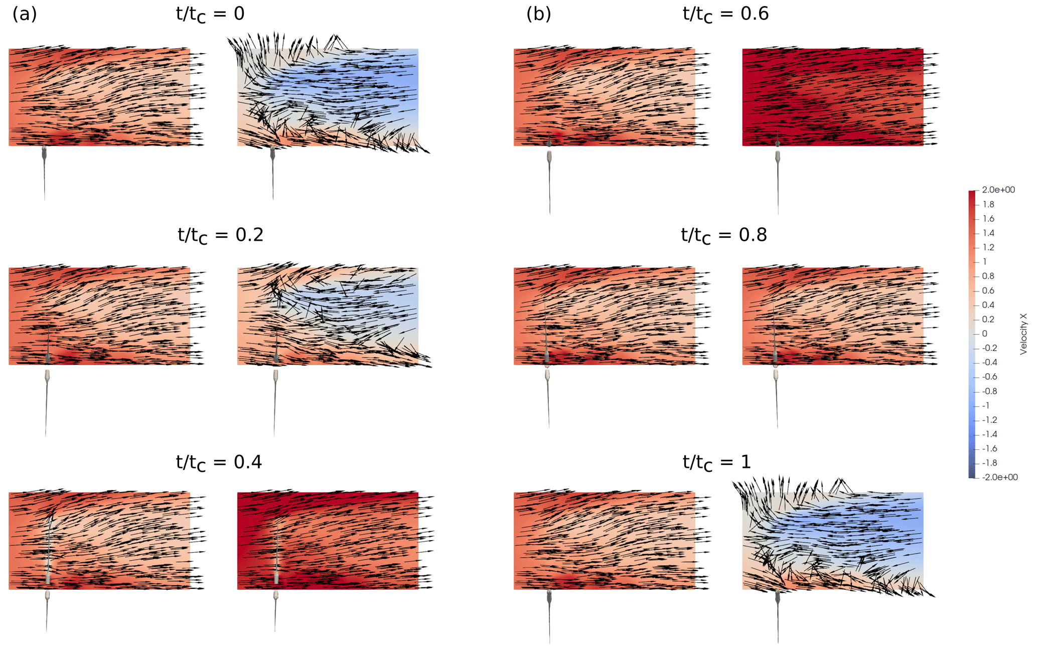
Figure 13Velocity field in the near wake of the UNAFLOW rotor during an oscillation cycle in LC 3.26. The color map is relative to axial (X) velocity, and vectors indicate the in-plane direction of the fluid. The absolute velocity field in the inertial reference frame is displayed in the left panel of each case, while the relative velocity field in the rotor reference frame obtained with Eq. (16) is displayed in the right panel. Only the upper half of the mid-wake is shown, as relative inflow variations are largest. (a) t tc between 0 and 0.4; (b) t tc between 0.6 and 1.0.
This is in line with the observations of Ferreira et al. (2022), who argue that TWS and VRS are a property of the stream tube rather than the rotor. Therefore, the high-induction factors observed in Fig. 12a are a consequence of rotor motion leading to localized flow reversal on the rotor rather than an indication of TWS or VRS. As discussed in Sect. 3.2, this fundamental flaw within the theory causes DBEM not to be able to match the predictions of LLFVW and ALM in the outer part of Blade 1 during LC 3.26 (Fig. 12a, c, e).
In this study, a critical analysis of the applicability and accuracy of BEM-based aerodynamic models in complex flow conditions typical of floating wind turbines is proposed. To this end, the aerodynamic forces resulting from forced surge and pitch oscillation tests of the UNAFLOW rotor are used. In an attempt to find the real limits of BEM, we also went beyond the UNAFLOW tests by analyzing oscillations with higher frequency and additional load cases in low wind speeds. The amplitude and frequency – 0.1 Hz at full scale – of these additional tests were selected to be representative of extreme wave-induced oscillations.
Results have shown that in rated wind speed conditions all models are able to capture the amplitude of the thrust force oscillations. In these conditions, there is a linear relation between the normalized amplitude and oscillation frequency. At high oscillation frequencies, the LLFVW model and ALM stop behaving linearly. This effect is ultimately linked to unsteady airfoil effects, namely Lowry's returning wake problem. BEM and DBEM results are unable to capture this behavior, despite including unsteady blade aerodynamics, as they do not model returning wake effects. The frequency at which these aerodynamic phenomena are most apparent depends on the specific rotor design. In fact, discrepancy between BEM results and higher-order wake theories is largest when the oscillation frequency is 3 times the revolution frequency – 12 Hz at model scale – but is also apparent at 8 Hz, a 33 % reduction with respect to the 3P frequency.
Analyzing the results of oscillating tests at 2 Hz with blade pitch and rotor speed oscillations, namely, LCs 2.12, 2.16, and 2.17, we have found that DBEM is able to predict thrust force variations that are in line with higher-fidelity models such as LLFVW and ALM. On the other hand, in line with the findings of previous studies (Bergua et al., 2023), simple BEM theory falls short of the other model predictions when blade pitch and rotor speed variations are introduced with the surge oscillations (LC 2.16 and 2.17). In addition, we have shown that the use of a model that can include dynamic inflow effects, either directly through model solution or empirically, lowers the variations in induced velocity in all three LCs. In other words, unsteady wake dynamics (also known as dynamic inflow) effectively act like a filter on induced velocities, diminishing their amplitude even in the case of surge oscillations only. The lack of a difference between BEM and higher-order theories in the case of simple surge oscillations (LC 2.12) is not due to a lack of unsteady aerodynamic effects but rather the way variations in induced velocity and structural velocity combine along the blade span, which explains the rotor thrust overshoot noted during rotor speed variations, the undershoot during blade pitch variation, and the substantial equivalency between aerodynamic theories in the case of surge variation only. It is also important to note that the amplitude of the induced velocity variation along the blade span in the three examined load cases is comparable. This differs from what is observed during surge velocity step tests, where, similar to LC 2.12, no dynamic inflow effects are observed. In this case, however, the absence of such effects is mostly attributed to the small variations in induced velocities that can be observed in the tests, in turn caused by the change in tip vortex spacing partially compensating for the change in axial induction factors.
Despite the inability to predict returning wake effects, DBEM is found to perform well at rated wind speed. In these conditions, treating the structural velocity as an apparent wind variation is practically effective and in line with the existing body of literature.
In lower wind speeds, near cut-in wind speed where rotor loading is high, DBEM is able to predict similar results to LLFVW and ALM as far as global rotor aerodynamic forces are concerned. On the other hand, when considering spanwise quantities along the blades some differences with respect to higher-order theories emerge. Applying the momentum balance in the rotor reference frame, as this method implies, means that induction factors can reach very high values during specific transient events. This does not necessarily imply that the rotor enters TWS or VRS, where momentum theory is invalid, as no flow reversal can be seen in the rotor wake despite induction factors exceeding unity. Flow reversal can instead be seen across the rotor plane, as this is due to the rotor structural velocity rather than the induced velocity. Because structural velocities are included in the momentum balance as apparent wind variations, BEM and DBEM cannot distinguish between flow reversal and VRS, and therefore, despite the good prediction of aggregated rotor aerodynamic forces, differences with respect to higher-order theories in the prediction of spanwise quantities are apparent. This highlights an area of possible future improvement in BEM-based engineering tools. For instance, the ability of a dynamic wake induction model to model the inertia in the flow of a floating rotor if structural velocity is not considered in the momentum balance, and possible improvements to these models in such a scenario, remains an open question.
In conclusion, dynamic inflow effects are present even in surge tests, despite there being little to no difference in the predicted global aerodynamic thrust variation. Similar to the observations of other authors, performing the momentum balance in the rotor-relative reference frame – effectively treating the structural velocity variation as a variation in inflow, despite being theoretically incorrect – is practically effective in the vast majority of the cases analyzed herein. In fact, once augmented with a dynamic inflow model, DBEM is able to predict aerodynamic thrust variation in most of the analyzed cases and still represents a valuable industrial tool in the case of emerging FOWT technology. However, treating structural velocities as variations in relative inflow leads to inconsistencies in the case of rotor–wake interaction, where DBEM is found to be unable to reproduce the results of LLFVW and ALM, an indication of both the limits of BEM and of an area of possible future improvement. Lastly, this work was carried out on a scaled 10 MW rotor. The outcomes of the analysis may be more significant in the context of ever larger rotors that are being prototyped and built, which may be more influenced by dynamic inflow effects, as wake-reduced frequency depends on the rotor diameter. Returning wake effects may also be more likely to arise since larger rotors typically feature lower revolution speeds. In addition, as these dynamic effects are more prominent at high oscillation frequencies, tension leg platforms, which feature high-pitch natural frequencies, could be affected by resonance and thus induce unsteady aerodynamic effects that may not be appropriately captured by BEM models. More research is therefore needed in this regard.
All data presented in the study are openly available upon request to the contact authors.
This study represents one of the main outcomes of FP's PhD research program. He conceptualized the study and the additional tests beyond the UNAFLOW experiments, reviewed existing work, performed the numerical simulations, analyzed the results, and wrote the first draft. AB provided guidance in the PhD research project, discussed the idea and the results, contributed to the analysis of results, and reviewed the paper. AR provided support for the discussion of the implications of the main findings in the field of floating offshore wind energy and reviewed the paper. JJ provided guidance in the analysis of NREL simulation tools and collaborated in the discussion of the results; he also reviewed the paper.
At least one of the (co-)authors is a member of the editorial board of Wind Energy Science. The peer-review process was guided by an independent editor, and the authors also have no other competing interests to declare.
The views expressed in the article do not necessarily represent the views of the DOE or the US Government. The US Government retains and the publisher, by accepting the article for publication, acknowledges that the US Government retains a nonexclusive, paid-up, irrevocable, worldwide license to publish or reproduce the published form of this work, or allow others to do so, for US Government purposes.
Publisher's note: Copernicus Publications remains neutral with regard to jurisdictional claims made in the text, published maps, institutional affiliations, or any other geographical representation in this paper. While Copernicus Publications makes every effort to include appropriate place names, the final responsibility lies with the authors.
The authors wish to thank Leonardo Pagamonci from the University of Florence for his support in running the ALM simulations, as well as Giovanni Ferrara of the University of Florence for his guidance during Francesco Papi's PhD program.
Convergent Science provided CONVERGE licenses and technical support for this work.
This work was authored in part by the National Renewable Energy Laboratory, operated by the Alliance for Sustainable Energy, LLC, for the US Department of Energy (DOE) under contract no. DE-AC36-08GO28308.
Funding for the work of the National Renewable Energy Laboratory was provided by the US Department of Energy's Office of Energy Efficiency and Renewable Energy Wind Energy Technologies Office.
This paper was edited by Joachim Peinke and reviewed by two anonymous referees.
Bak, C., Zahle, F., Bitsche, R., Kim, T., Yde, A., Henriksen, L. C., Natarajan, A., and Hansen, M.: Description of the DTU 10 MW Reference Wind Turbine, DTU Wind Energy, https://www.studocu.com/da/document/danmarks-tekniske-universitet/engelsk-1-us-civics-and-academic-writing-1/dtu-wind-energy-report-i-0092/46768724 (last access: 29 April 2024), 2013.
Bayati, I., Belloli, M., Bernini, L., Fiore, E., Giberti, H., and Zasso, A.: On the functional design of the DTU10 MW wind turbine scale model of LIFES50+ project, J. Phys. Conf. Ser., 753, 052018, https://doi.org/10.1088/1742-6596/753/5/052018, 2016.
Bayati, I., Belloli, M., Bernini, L., and Zasso, A.: A Formulation for the Unsteady Aerodynamics of Floating Wind Turbines, With Focus on the Global System Dynamics, in: Volume 10: Ocean Renewable Energy, ASME 2017 36th International Conference on Ocean, Offshore and Arctic Engineering, Trondheim, Norway, 25–30 June 2017, V010T09A055, https://doi.org/10.1115/OMAE2017-61925, 2017a.
Bayati, I., Belloli, M., Bernini, L., Giberti, H., and Zasso, A.: Scale model technology for floating offshore wind turbines, IET Renew. Power Gen., 11, 1120–1126, https://doi.org/10.1049/iet-rpg.2016.0956, 2017b.
Bergua, R., Robertson, A., Jonkman, J., Branlard, E., Fontanella, A., Belloli, M., Schito, P., Zasso, A., Persico, G., Sanvito, A., Amet, E., Brun, C., Campaña-Alonso, G., Martín-San-Román, R., Cai, R., Cai, J., Qian, Q., Maoshi, W., Beardsell, A., Pirrung, G., Ramos-García, N., Shi, W., Fu, J., Corniglion, R., Lovera, A., Galván, J., Nygaard, T. A., dos Santos, C. R., Gilbert, P., Joulin, P.-A., Blondel, F., Frickel, E., Chen, P., Hu, Z., Boisard, R., Yilmazlar, K., Croce, A., Harnois, V., Zhang, L., Li, Y., Aristondo, A., Mendikoa Alonso, I., Mancini, S., Boorsma, K., Savenije, F., Marten, D., Soto-Valle, R., Schulz, C. W., Netzband, S., Bianchini, A., Papi, F., Cioni, S., Trubat, P., Alarcon, D., Molins, C., Cormier, M., Brüker, K., Lutz, T., Xiao, Q., Deng, Z., Haudin, F., and Goveas, A.: OC6 project Phase III: validation of the aerodynamic loading on a wind turbine rotor undergoing large motion caused by a floating support structure, Wind Energ. Sci., 8, 465–485, https://doi.org/10.5194/wes-8-465-2023, 2023.
Bernini, L., Bayati, I., Boldrin, D. M., Cormier, M., Carboni, M., and Mikkelsen, R.: UNsteady Aerodynamics for Floating Wind (UNAFLOW), IRPWIND, 2018.
Boorsma, K. and Caboni, M.: Numerical analysis and validation of unsteady aerodynamics for floating offshore wind turbines, TNO, Delft, the Netherlands, https://publications.tno.nl/publication/34637340/MelXUe/TNO-2020-R11345.pdf (last access: 29 April 2024), 2020.
Boorsma, K., Wenz, F., Lindenburg, K., Aman, M., and Kloosterman, M.: Validation and accommodation of vortex wake codes for wind turbine design load calculations, Wind Energ. Sci., 5, 699–719, https://doi.org/10.5194/wes-5-699-2020, 2020.
Buhl Jr., M. L.: New Empirical Relationship between Thrust Coefficient and Induction Factor for the Turbulent Windmill State, Technical Report NREL/TP-500-36834, National Renewable Energy Laboratory, https://doi.org/10.2172/15016819, 2005.
Burton, T. (Ed.): Wind energy: handbook, J. Wiley, Chichester, New York, 617 pp., ISBN 9781119992714, 2001.
Cioni, S., Papi, F., Pagamonci, L., Bianchini, A., Ramos-García, N., Pirrung, G., Corniglion, R., Lovera, A., Galván, J., Boisard, R., Fontanella, A., Schito, P., Zasso, A., Belloli, M., Sanvito, A., Persico, G., Zhang, L., Li, Y., Zhou, Y., Mancini, S., Boorsma, K., Amaral, R., Viré, A., Schulz, C. W., Netzband, S., Soto-Valle, R., Marten, D., Martín-San-Román, R., Trubat, P., Molins, C., Bergua, R., Branlard, E., Jonkman, J., and Robertson, A.: On the characteristics of the wake of a wind turbine undergoing large motions caused by a floating structure: an insight based on experiments and multi-fidelity simulations from the OC6 project Phase III, Wind Energ. Sci., 8, 1659–1691, https://doi.org/10.5194/wes-8-1659-2023, 2023.
Corniglion, R., Harris, J. C., and Peyrard, C.: The aerodynamics of a blade pitch, rotor speed, and surge step for a wind turbine regarding dynamic inflow, Wind Energy, 25, 858–880, https://doi.org/10.1002/we.2702, 2022.
Damiani, R. R. and Hayman, G.: The Unsteady Aerodynamics Module For FAST8, Technical Report NREL/TP-5000-66347, National Renewable Energy Laboratory, https://doi.org/10.2172/1576488, 2019.
de Vaal, J. B., Hansen, M. H., and Moan, T.: Effect of wind turbine surge motion on rotor thrust and induced velocity, Wind Energy, 17, 105–121, https://doi.org/10.1002/we.1562, 2012.
Ferreira, C., Yu, W., Sala, A., and Viré, A.: Dynamic inflow model for a floating horizontal axis wind turbine in surge motion, Wind Energ. Sci., 7, 469–485, https://doi.org/10.5194/wes-7-469-2022, 2022.
Fontanella, A., Bayati, I., Mikkelsen, R., Belloli, M., and Zasso, A.: UNAFLOW: a holistic wind tunnel experiment about the aerodynamic response of floating wind turbines under imposed surge motion, Wind Energ. Sci., 6, 1169–1190, https://doi.org/10.5194/wes-6-1169-2021, 2021.
Hansen, M. O. L.: Aerodynamics of wind turbines, 2nd edn., Earthscan, London, Sterling, VA, 181 pp., ISBN 978-1-84407-438-9, 2008.
Jost, E., Klein, L., Leipprand, H., Lutz, T., and Krämer, E.: Extracting the angle of attack on rotor blades from CFD simulations, Wind Energy, 21, 807–822, https://doi.org/10.1002/we.2196, 2018.
Leishman, J. G.: Principles of Helicopter Aerodynamics, Cambridge University Press, 866 pp., ISBN 978-1-107-01335-3, 2016.
Mancini, S., Boorsma, K., Caboni, M., Cormier, M., Lutz, T., Schito, P., and Zasso, A.: Characterization of the unsteady aerodynamic response of a floating offshore wind turbine to surge motion, Wind Energ. Sci., 5, 1713–1730, https://doi.org/10.5194/wes-5-1713-2020, 2020.
Mancini, S., Boorsma, K., Caboni, M., Hermans, K., and Savenije, F.: An engineering modification to the blade element momentum method for floating wind turbines, J. Phys. Conf. Ser., 2265, 042017, https://doi.org/10.1088/1742-6596/2265/4/042017, 2022.
Matha, D.: Model Development and Loads Analysis of an Offshore Wind Turbine on a Tension Leg Platform, with a Comparison to Other Floating Turbine Concepts, University of Colorado, Boulder, https://doi.org/10.2172/973961, 2009.
Ning, A., Hayman, G., Damiani, R., and Jonkman, J. M.: Development and Validation of a New Blade Element Momentum Skewed-Wake Model within AeroDyn, in: 33rd Wind Energy Symposium, 33rd Wind Energy Symposium, Kissimmee, Florida, 5–9 January 2015, https://doi.org/10.2514/6.2015-0215, 2015.
Ning, A. S.: A simple solution method for the blade element momentum equations with guaranteed convergence: Guaranteed solution of the BEM equations, Wind Energy, 17, 1327–1345, https://doi.org/10.1002/we.1636, 2013.
Øye, S.: Tjæreborg Wind Turbine: 4. dynamic inflow measurement, Tjæreborg Wind Turbine, Lyngby, https://orbit.dtu.dk/en/publications/tj%C3%A6reborg-wind-turbine-4-dynamic-inflow-measurement (last access: 29 April 2024), 1991.
Pagamonci, L., Papi, F., Balduzzi, F., Xie, S., Sadique, J., Scienza, P., and Bianchini, A.: To what extent is aeroelasticity impacting multi-megawatt wind turbine upscaling? A critical assessment, J. Phys. Conf. Ser., 2648, 012005, https://doi.org/10.1088/1742-6596/2648/1/012005, 2023.
Papi, F. and Bianchini, A.: Technical challenges in floating offshore wind turbine upscaling: A critical analysis based on the NREL 5 MW and IEA 15 MW Reference Turbines, Renew. Sust. Energ. Rev., 162, 112489, https://doi.org/10.1016/j.rser.2022.112489, 2022.
Papi, F., Perignon, Y., and Bianchini, A.: Derivation of Met-Ocean Conditions for the Simulation of Floating Wind Turbines: a European case study, J. Phys. Conf. Ser., 2385, 012117, https://doi.org/10.1088/1742-6596/2385/1/012117, 2022.
Patryniak, K., Collu, M., and Coraddu, A.: Rigid Body Dynamic Response of a Floating Offshore Wind Turbine to Waves: Identification of the Instantaneous Centre of Rotation Through Analytical And Numerical Analyses, Renew. Energ., 218, 119378, https://doi.org/10.1016/j.renene.2023.119378, 2023.
Perez-Becker, S., Papi, F., Saverin, J., Marten, D., Bianchini, A., and Paschereit, C. O.: Is the Blade Element Momentum theory overestimating wind turbine loads? – An aeroelastic comparison between OpenFAST's AeroDyn and QBlade's Lifting-Line Free Vortex Wake method, Wind Energ. Sci., 5, 721–743, https://doi.org/10.5194/wes-5-721-2020, 2020.
Ramachandran, G. K. V., Robertson, A., Jonkman, J. M., and Masciola, M. D.: Investigation of Response Amplitude Operators for Floating Offshore Wind Turbines: Preprint, National Renewable Energy Lab (NREL), Golden, CO (United States), https://www.osti.gov/biblio/1087800 (last access: 29 April 2024), 2013.
Ramos-García, N., Kontos, S., Pegalajar-Jurado, A., González Horcas, S., and Bredmose, H.: Investigation of the floating IEA Wind 15 MW RWT using vortex methods Part I: Flow regimes and wake recovery, Wind Energy, 25, 468–504, https://doi.org/10.1002/we.2682, 2022.
Ribeiro, A. F. P., Casalino, D., and Ferreira, C. S.: Surging Wind Turbine Simulations with a Free Wake Panel Method, J. Phys. Conf. Ser., 2265, 042027, https://doi.org/10.1088/1742-6596/2265/4/042027, 2022.
Ribeiro, A. F. P., Casalino, D., and Ferreira, C. S.: Nonlinear inviscid aerodynamics of a wind turbine rotor in surge, sway, and yaw motions using a free-wake panel method, Wind Energ. Sci., 8, 661–675, https://doi.org/10.5194/wes-8-661-2023, 2023.
Richards, K. J., Senecal, P. K., and Pomraning, E.: CONVERGE 3.0, Convergent Science, Madison, WI, 2023.
Schepers, G.: Pragmatic Models: BEM with Engineering Add-Ons, in: Handbook of Wind Energy Aerodynamics, edited by: Stoevesandt, B., Schepers, G., Fuglsang, P., and Sun, Y., Springer International Publishing, Cham, 393–436, https://doi.org/10.1007/978-3-030-31307-4_19, 2022.
Schulz, C. W., Netzband, S., Özinan, U., Cheng, P. W., and Abdel-Maksoud, M.: Wind turbine rotors in surge motion: new insights into unsteady aerodynamics of floating offshore wind turbines (FOWTs) from experiments and simulations, Wind Energ. Sci., 9, 665–695, https://doi.org/10.5194/wes-9-665-2024, 2024.
Sebastian, T. and Lackner, M. A.: Characterization of the unsteady aerodynamics of offshore floating wind turbines: Unsteady aerodynamics of offshore floating wind turbines, Wind Energy, 16, 339–352, https://doi.org/10.1002/we.545, 2013.
Shaler, K., Branlard, E., and Platt, A.: OLAF User's Guide and Theory Manual, National Renewable Energy Lab (NREL), Golden, CO (United States), https://doi.org/10.2172/1659853, 2020.
Snel, H. and Schepers, J. G.: Joint investigation of dynamic inflow effects and implementation of an engineering method, Technical Report ECN-C–94-107, ECN Wind Energy, https://publications.ecn.nl/E/1995/ECN-C--94-107 (last access: 29 April 2024), 1995.
Sørensen, J. N. and Shen, W. Z.: Numerical Modeling of Wind Turbine Wakes, J. Fluid. Eng.-T. ASME, 124, 393–399, https://doi.org/10.1115/1.1471361, 2002.
Sørensen, J. N., Shen, W. Z., and Munduate, X.: Analysis of wake states by a full-field actuator disc model, Wind Energy, 1, 73–88, https://doi.org/10.1002/(SICI)1099-1824(199812)1:2<73::AID-WE12>3.0.CO;2-L, 1998.
Van Garrel, A.: Development of a wind turbine aerodynamics simulation module, Technical Report ECN-C–03-079, ECN Wind Energy, https://publications.ecn.nl/WIN/2003/ECN-C--03-079 (last access: 29 April 2024), 2003.
Veers, P., Dykes, K., Basu, S., Bianchini, A., Clifton, A., Green, P., Holttinen, H., Kitzing, L., Kosovic, B., Lundquist, J. K., Meyers, J., O'Malley, M., Shaw, W. J., and Straw, B.: Grand Challenges: wind energy research needs for a global energy transition, Wind Energ. Sci., 7, 2491–2496, https://doi.org/10.5194/wes-7-2491-2022, 2022.
Xie, S.: An actuator-line model with Lagrangian-averaged velocity sampling and piecewise projection for wind turbine simulations, Wind Energy, 24, 1095–1106, https://doi.org/10.1002/we.2619, 2021.