the Creative Commons Attribution 4.0 License.
the Creative Commons Attribution 4.0 License.
 | 07 May 2024
Effect of scour on the fatigue life of offshore wind turbines and its prevention through passive structural control
Yu Cao
Ningyu Wu
Jigang Yang
Ronghua Zhu
Xugang Hua
Offshore wind turbine (OWT) support structures are exposed to the risk of fatigue damage and scour, and this risk can be effectively mitigated by installing structural control devices such as tuned mass dampers (TMDs). However, time-varying scour altering OWTs' dynamic characteristics has an impact on the TMD design and fatigue life, which has rarely been studied before. In this paper, a simplified modal model is used to investigate the influence of scour and a TMD on the fatigue life evaluation of a 5 MW OWT's support structure, and a traditional method and a newly developed optimization technique are both presented to obtain TMD parameters. This optimization technique aims at finding optimal parameters of the TMD which maximize the fatigue life of a hotspot at the mudline, and the effect of time-varying scour can be considered. This study assumes that the TMD operates in the fore–aft (FA) direction, while the vibration in the side–side (SS) direction is uncontrolled. Results show that scour can decrease the fatigue life by about 24.1 % and that the TMD can effectively suppress vibration and increase the fatigue life. When the scour depth reaches 1.3 times the pile diameter, the TMD with a mass ratio of 1 % can increase the fatigue life of an OWT's support structure by about 64.6 %. Further, it is found that the fatigue life can be extended by 25 % with the TMD optimized by the proposed optimization technique rather than using a traditional design method which does not take the change in dynamic characteristics into account.
- Article
(4035 KB) - Full-text XML
- BibTeX
- EndNote


With the continuous development of large-size fixed-bottom OWTs, local scour and scour protection of pile foundation have become a common issue (Wang et al., 2020; Wang et al., 2019; Zhang et al., 2022). Scour has a significant impact on the dynamic characteristics, vibration magnitudes, and thus fatigue life of OWTs under wind and wave loads. On the one hand, the action of currents and waves causes local scour pits around pile foundations, which reduces the burial depth of pile foundations. This phenomenon usually causes a reduction in the natural frequencies of OWTs and changes in other dynamic characteristics. This can potentially lead to resonance, large-amplitude stress cycles, and fatigue damage when one of the natural frequencies is close to the rotational frequency of the blades (Sørensen and Ibsen, 2013). On the other hand, current scour protection measures cannot completely avoid scour and have their own shortcomings. For example, armouring protection has the disadvantage that the projectile cannot be accurately cast in complex sea conditions and is easy to be washed away (Wang et al., 2023; Zhang et al., 2023). Flow-altering protection has the disadvantages of high cost and changing the dynamic characteristics of the foundation (Tang et al., 2023). As offshore structures, wind turbines are vulnerable to corrosion from seawater, which makes the fatigue problem worse (Amirafshari et al., 2021). Thus, the scour-induced changes in dynamic characteristics and the risk in resonance inevitably induce a further increase in fatigue damage and deserve in-depth research (Mayall et al., 2018).
Many researchers have studied the effect of scour on fatigue damage accumulation in OWTs. For instance, van der Tempel (2006) investigated the frequency and fatigue of piles under different scour depths and concluded that scour has little effect on the natural frequencies but a major effect on fatigue damage. Zhang et al. (2021) found that scour depth has a significant influence on monopile impedance. Rezaei et al. (2018) showed that scour leads to an increase in the maximum bending moment of the monopile and a shortening of the fatigue life. Installing structural control devices is an effective way to mitigate the fatigue damage to OWTs. It was demonstrated that TMDs have a positive effect on reducing vibration amplitudes of wind turbine systems (Lackner and Rotea, 2011a; Dinh and Basu, 2015; Lu et al., 2023; Aydin et al., 2023). K. Dai et al. (2021) conducted a shaker experiment using a scaled wind turbine model and showed that the installed TMD can suppress the vibration of the structure more effectively considering soil–structure interaction (SSI).
In the previously mentioned studies, researchers have individually investigated the effect of scour on the structural vibration and fatigue and the structural control of TMDs for OWTs. However, in practice, the effect of scour combining structural control via TMDs could have a significant impact on OWTs' fatigue life. Moreover, whether considering scour could influence the design of TMDs and TMDs with different parameters can also have an impact on fatigue damage accumulation.
The purpose of this study is to explore the effect of scour on the fatigue life of wind turbine structures and the control effect of a TMD on the fatigue life of wind turbine structures under scour conditions. The authors present a case study with a 5 MW single-pile wind turbine to carry out related research. In this study, the software Abaqus is used to establish a detailed SSI model with different scour depths. A finite-element (FE) model which considers wind loads and TMD is established in MATLAB, and the scour effect is considered by establishing a relationship with the Abaqus model by means of the equivalent stiffness matrix. The finite-element model is also simplified to a modal model in order to achieve fast prediction of fatigue life. The TMD operates in the fore–aft (FA) direction and does not work in the side–side (SS) direction. This study investigates the effect of different scour depths on the performance of the TMD and the fatigue life of a 5 MW OWT's support structure, including a tower and a monopile foundation, and the optimization of the TMD's parameters considering time-varying scour depths to maximize fatigue life is also presented. This study provides some knowledge of the effects of the time-varying scour and the TMD on the fatigue life of wind turbines and a new TMD design method targeting the enhancement of fatigue resistance. The rest of the paper is organized as follows: Section 2 introduces the numerical models used in the research. Section 3 introduces the traditional TMD design method and the newly developed parameter optimization method. Section 4 describes the load cases for the fatigue analysis, the analysis results of this study, and the TMD parameter optimization results. Section 5 concludes the study.
2.1 Finite-element model and implementation of tuned mass damper
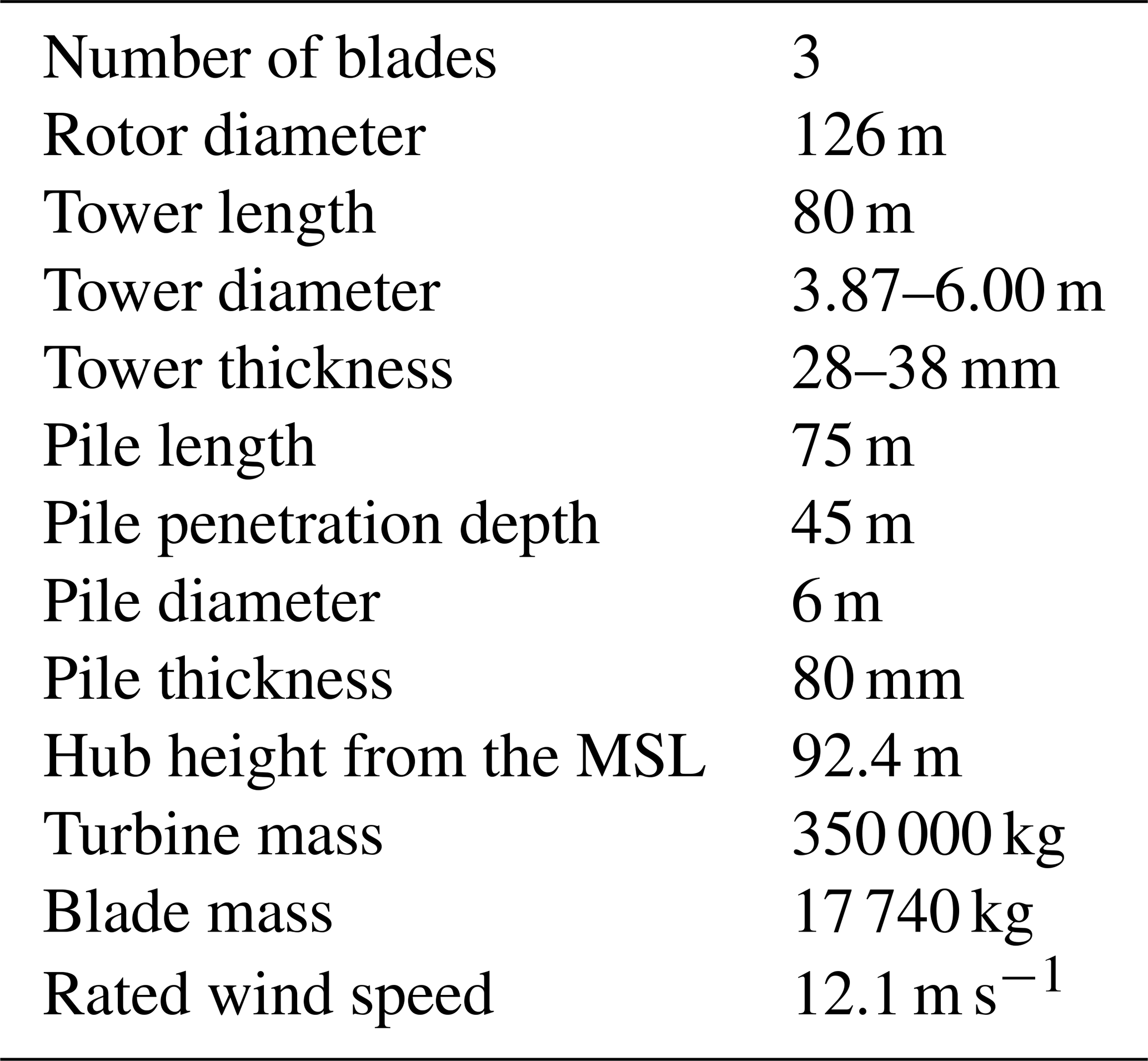
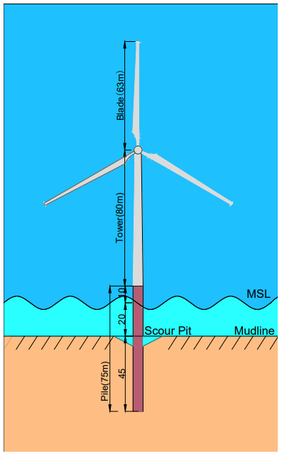
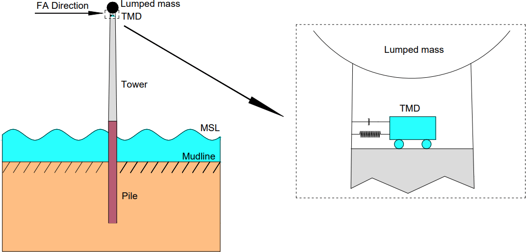
An FE model of a monopile-supported OWT installed with a TMD is established in MATLAB. This model contains a flexible tower, a rotor–nacelle assembly (RNA), and an external TMD, which consider the foundation flexibility. As shown in Fig. 1, the model is based on the widely used National Renewable Energy Laboratory (NREL) 5 MW reference OWT, and its detailed properties are shown in Table 1. Three-dimensional beam elements are used to create the FE model, and the theoretical basis is the standard Euler–Bernoulli beam theory. The wind turbine tower is divided into 18 beam elements, and the monopile between the mudline and the mean sea level (MSL) is divided into 4 beam elements. A convergence test performed by comparing the first natural frequencies shows that 22 beam elements are sufficient. Each element node has 6 degrees of freedom (DOFs) corresponding to translational and rotational motions in various directions. The mass matrix and stiffness matrix in the equation of motion of the OWT structure can be obtained using the material properties. The damping matrix is applied by means of Rayleigh damping, and the combined damping ratio of soil damping and structural damping is assumed to be 1 % (Chen and Duffour, 2018). The Rayleigh mass and stiffness coefficients, α1 and α2, are defined by . The variable ω is the natural frequency of the first FA mode, and ζC is the combined damping ratio. The RNA is represented by a lumped mass at the tower top.
Table 1Basic properties of the NREL 5 MW reference OWT (Jonkman et al., 2009; Rezaei, 2017).
The TMD is mounted on the top of the tower, and the effect of the TMD is considered by incorporating its mass, damping, and stiffness terms at relevant positions in the local mass, damping, and stiffness matrices of the beam element representing the top of the tower. The equation of motion of the OWT main structure is
where Ms, Cs, and Ks are the mass, damping, and stiffness matrices of the main structure. CT and KT are matrices with the same dimensions containing cT and kT; . Us is the displacement vector of the main structure; . UT is the displacement vector containing uT; . Fwind and Fwave are the aerodynamic and wave load vectors. The equation of motion for the TMD can be represented by
where mT,cT, and kT are the mass, damping, and stiffness values of the TMD and uT and us-top are the displacement of the TMD and the displacement of the top node. The modelling of the SSI is realized by an equivalent stiffness matrix, which will be introduced in detail subsequently in Sect. 2.3.
Wind loads were calculated using modified unsteady blade element momentum (BEM) theory (Branlard, 2017; Jonkman and Buhl, 2006) with Prandtl–Glauert corrections. Ignoring the iterative loop (Chen et al., 2021b) in the steady-state BEM code, the instantaneous aerodynamic forces were calculated for each time step within the time integration. The turbulent wind field was generated using the Kaimal spectrum according to the wind field parameters of International Electrotechnical Commission (2019), assuming moderate turbulence intensity. It should be noted that the aerodynamic loads from the rotor applied at the tower top were calculated using an aerodynamic force linearization technique previously developed by the authors (Chen et al., 2021a; Chen et al., 2020). This technique divides the aerodynamic loads into two parts. The first part is the quasi-steady aerodynamic force calculated by the BEM theory, which does not consider the influence of tower top motion. The second part considers the effect of aerodynamic damping by introducing an additional aerodynamic damping matrix. The adoption of this technique aims to facilitate the development of a simplified modal model for rapid fatigue calculation, which will be introduced in detail in Sect. 2.4. To represent the influence of the controller in the OWT, a standard relationship (Jonkman et al., 2009) between the mean wind speed, rotor rotation speed, and blade pitch angles, which represent the OWT's normal operational conditions, is adopted throughout the wind loading calculations.
Wave loads were calculated using the Morison equation, which includes viscous drag and inertial forces:
where and are the velocity and acceleration vectors of water particles, Cd is the drag coefficient, Dpile is the diameter of the monopile between the mean sea level and the mudline, Cm is the inertia coefficient, and ρw is the density of water. Cd and Cm were chosen as 1 and 2 respectively as the recommended values in Shirzadeh et al. (2013). The wave profiles were obtained through the superposition of wave components, combining linear wave theory and the Joint North Sea Wave Project (JONSWAP) spectra (Hasselmann et al., 1973). The application of wind and wave loads is shown in Fig. 2.

2.2 Scour modelling in Abaqus
Using solid elements to model pile–soil interaction (S. Dai et al., 2021; Fard et al., 2022; Ma and Chen, 2021; Zdravković et al., 2015) is usually considered more accurate than the p–y-curve method (Liang et al., 2018; Song and Achmus, 2023) and the equivalent embedding method (Shahmohammadi and Shabakhty, 2020; Bergua et al., 2022). The solid-element method can also reduce the influence of an empirical formula on the results. Therefore, the solid-element method is used to establish the wind turbine scour model. The wind turbine scour model established in Abaqus contains soil, pile foundation, and tower, and the RNA is replaced by a concentrated mass located at the top of the tower. The diameter of the soil body is selected as 20 times the pile diameter, the soil under the pile foundation is selected as 2.5 times the pile diameter, and the total height of the soil body is 60 m. The soil body is made of homogeneous dense sandy soil, and the pile and tower are made of steel. The material parameters of the soil body, pile, and tower are shown in Table 2.

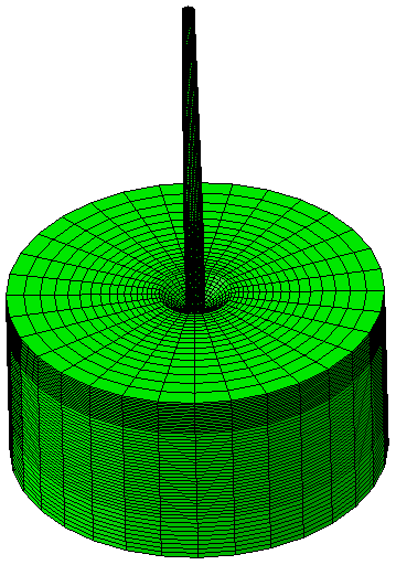
The Mohr–Coulomb model is used for the soil, and the pile, tower, and nacelle are assumed to be elastic since they are much stiffer than the soil and do not deform plastically under normal operational conditions. The pile and tower are connected with a binding relationship. The normal contact between the pile and soil adopts the hard contact, and the tangential contact adopts the friction penalty function. The relative sliding friction factor at the interface, μ, is equal to tan (0.75 φ), where φ is the internal friction angle. The pile–soil contact is in the form of frictional contact, where mutual contact pairs are established between the pile and the soil, including the contacts between the pile bottom surface and the soil, the outside surface of the pile and the soil, and the inside surface of the pile and the soil core. The frictional contact between the pile bottom surface and soil is omitted due to the small area of the contact surface. These frictional contacts all adopt the face-to-face contact, and the contact discretization method adopts the face-to-face discretization method, considering the large stiffness of the main surface and the small stiffness of the slave surface. The perimeter of the soil body is translationally constrained, and the bottom surface of the soil adopts a fixed constraint. The eight-node linear brick element (C3D8R) is used to model the pile and soil, and the mesh division is realized by arranging seeds as shown in Fig. 3. The whole model is set up by adopting the modelling method of “element birth and death”, which makes the initial soil stress balance operation possible and sets up contacts and other related steps by killing and activating relevant elements.
The scour conditions can be represented by a deep conical pit around the pile under the long-term action of the waves and currents. According to the specification by Det Norske Veritas (DNV) (Det Norske Veritas AS, 2014b), the radius of the pit surface formed by scour, R, can be related to the depth of the scour pit by
where D is the diameter of the pile, S is the scour depth, and φ is the angle of the internal friction of the soil.
2.3 Equivalent stiffness matrix method
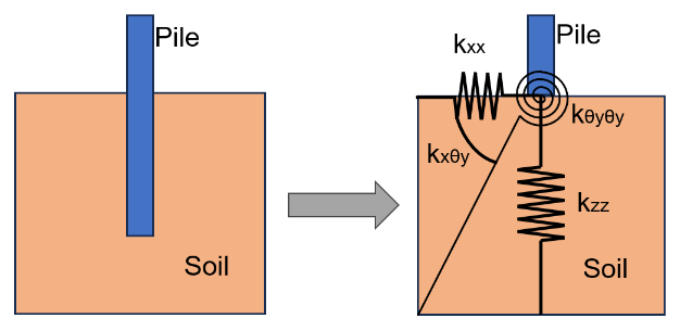
It is necessary to consider the effect of scour in the FE model in MATLAB. An equivalent stiffness matrix method is adopted in the FE model to consider the flexibility induced by the SSI. The 6 DOFs of nodes at the mudline are assumed to be constrained by a series of coupled springs, and the stiffness values of the coupled springs form a 6×6 stiffness matrix. For a specific stiffness term used in the FE model – for instance, the one relevant to the lateral displacement in the FA direction – the value of the stiffness term can be found from the relationship between the reaction force at the mudline and the pile top displacement (Jung et al., 2015). The equivalent stiffness schematic of the pile–soil interaction in the FA direction for the OWT is shown in Fig. 4.
According to the principle of virtual displacement and with the DOFs in other directions constrained, a unit displacement or rotation is first applied in one direction, and then the reaction force in that direction can be determined. The equivalent stiffness in that direction can be subsequently calculated by the relationship between the displacement and reaction force. Using the same approach, the stiffness terms corresponding to the remaining 5 DOFs are calculated. The stiffness terms in all 6 DOFs together form all the diagonal terms of the soil stiffness matrix. With the diagonal terms known, the off-diagonal stiffness terms can be found by applying a unit displacement in one direction and looking at the reaction force in the other concerned direction, with the other 4 DOFs constrained. Using the same principle, the off-diagonal terms can also be found from the relationship between the displacements and reaction forces, which ultimately results in a 6×6 stiffness matrix (Bergua et al., 2021; Pedersen and Askheim, 2021):
where Ksoil is the equivalent soil stiffness matrix, usoil is the displacement vector, and Fsoil is the reaction force vector. The equivalent soil stiffness matrix ignores the nonlinearity in the force–displacement relationship. This approach is suitable for fatigue analysis, as in normal operation conditions, the deformation of the soil around the monopile is relatively small and the nonlinearity in soil stiffness is very weak. The 6×6 soil stiffness matrix obtained from Abaqus is imported into the FE model in MATLAB. This modelling method combines the accuracy enhancement provided by the scour model in Abaqus using solid elements with the fast calculation speed and convenience of applying wind and wave loads using the FE model in MATLAB.
2.4 Rapid fatigue evaluation method
The established FE model in MATLAB can generate dynamic responses of the OWT, considering the wind and wave loads and the scour effect. However, a comprehensive fatigue life prediction in time domain needs to consider a large number of environmental states and load cases, so simulation efficiency is very important. Moreover, the TMD design optimization requires much more dynamic response time series. The FE model is not fast enough in this case. Therefore, a simplified modal model is developed from the FE model in MATLAB following the method developed in Chen et al. (2021b). The total aerodynamic forces from the rotor applied on the tower top node are linearized as the sum of a term corresponding to the forces for an assumed rigid tower and a term proportional to the tower top linear and angular velocities. The hydrodynamic forces are linearized by ignoring the relatively small monopile vibrations. The details of the force linearization can be found in a previous study by the authors (Chen et al., 2021a). Since the dynamic responses of the OWT are mainly dominated by the first two bending vibration modes, the FE model is reduced to a 4-DOF simplified modal model by considering only the first two bending modes in the FA and SS directions respectively. The development of the simplified 4-DOF modal model is briefly introduced as follows. Denoting the mass matrix and stiffness matrix of the OWT as M and K, including the TMD and the lumped soil stiffness matrix, the undamped vibration mode matrix, Ψ, can be obtained directly through eigen analysis. According to the relationship u=Ψα and multiplying the transpose of the undamped vibration matrix ΨT with the equation of motion, the following equation is obtained:
Then, the above equation can be rewritten as
where α is the general coordinate vector, is the modal mass matrix, is the modal damping matrix, is the modal stiffness matrix, and the modal load vector. Truncating Eq. (6) by only considering the first two bending modes, the FE model is reduced to a 4-DOF modal model, which can be used for a rapid fatigue analysis. The dynamic responses of the OWTs can be obtained by modal superposition after solving the general coordinate vector by time integration. In the 4-DOF simplified modal model, the cross section stress at any height can be calculated from the calculated node displacements. According to the dynamic stress extraction method provided by Pelayo et al. (2015), the cross section stress, σZ(t), at any moment at a given location can be obtained by
where ue is the nodal displacement vector at the cross section, E is the material elastic modulus, and Ne is the elemental shape function vector of the FE model; subscripts x and y are the positions within the section at height z of the tower. After the cyclic counting of the stress time series using the rainfall counting method, the fatigue damage at the hotspot can be evaluated by utilizing the Palmgren–Miner rule based on the S–N fatigue calculation method. According to the DNV (Det Norske Veritas AS, 2014a) and considering the thickness effect, the S–N curve for steel under water can be obtained by the following equation:
where N is the number of cycles to failure and Δσ is the stress range. The variable Δσ is calculated from the nominal stress Δσnominal by the equation , and SCF is the stress concentration factor. The variable m is the negative inverse slope of the S–N curve, is the intercept between the log N axis and the S–N curve, tref is the reference thickness for welded joints, and t is the thickness at which cracks may grow. Finally, t=tref is used for a thickness lower than tref. When t is larger than tref, t is the actual thickness of the pile. The variable k is the thickness exponent of the fatigue strength. For pile joints, the reference thickness, tref, is 25 mm. According to the DNV code, a bilinear S–N curve is usually used for offshore structures subjected mainly to typical wind and wave loads, using the class-E structural detail S–N curve shown in Table 3.

For stresses with variable amplitudes, the fatigue damage index is calculated using the Palmgren–Miner summation rule:
where Nc is the total number of bins, ni is the number of cycles in ith stress bin, Ni is the number of cycles to failure for the ith stress range, and Dk is the total fatigue damage index. The rainflow function in MATLAB is used for rainflow counting. When a stress time history is provided, this function can automatically calculate the ith stress range and the corresponding cycle number, ni; Nc is the total number of stress ranges. Fatigue failure occurs at the hotspot when the fatigue damage index reaches 1.
Installing damping devices can efficiently reduce the vibration amplitudes of OWTs so that their service life can be greatly prolonged. Using TMDs as passive control devices is the most widely used method of controlling the vibration of OWT support structures. Usually, most TMDs are designed based on the dynamic characteristics of the OWTs determined in the preliminary design stage, without considering the changes in dynamic properties that may be caused by scour and soil degradation. In the real environment, scour can alter the dynamic characteristics of OWTs, potentially reducing the effectiveness of installed dampers or rendering them completely ineffective. Therefore, it is of great significance to consider the changes in dynamic properties caused by scour on the TMD design. The following two subsections first introduce the traditional TMD design method considering constant dynamic characteristics in the initial state. Then, an optimal parameter search method for the design of TMDs is presented, taking into account the effects of scour and the fatigue life evaluation.
3.1 TMD design in initial state
As the dominant vibration mode of the OWT structure in operation is the first bending mode, the largest vibration amplitude occurs at the top of the tower, making the installation of the TMD at the tower top most effective. Therefore, the TMD is installed inside the steel tube at the tower top mainly to control the vibration in the FA direction, as shown in Fig. 5. Also, the TMD can be aligned with the FA direction by rotating the damper. Accordingly, the initial design of the TMD is mainly created based on the dynamic properties of the first-order mode. The initial design is used based on the assumption that the monopile foundation is not scoured.
Numerous studies have shown that a TMD can effectively suppress the vibration of a main structure when the mass ratio of the TMD to the main structure is 1 %–2 % (Lackner and Rotea, 2011b; Zhang et al., 2019). After determining the mass ratio, according to the classic TMD optimization theory proposed by Den Hartog (1957), the optimal frequency ratio of the TMD to the OWT structure is
The optimal damping ratio for the TMD can be calculated by
where μ is the mass ratio of the TMD to the OWT structure, αopt is the optimal frequency ratio of the TMD to the OWT structure, and ξopt is the optimal damping ratio of the TMD.
Considering that excessive mass would lead to increased construction costs, difficulties, and changes in the inherent characteristics of the original structure, the mass ratio of the TMD system to the main structure is initially set to 1 %. Moreover, previous studies have found that a tuned liquid column damper (TLCD) with a mass ratio of 1 % and a TMD with a mass ratio of 2 % can effectively suppress vibration (Colwell and Basu, 2009; Lackner and Rotea, 2011b; Zhang et al., 2019). According to Den Hartog's optimization theory for the initial TMD design, it can be determined that the optimal frequency ratio of the TMD to the main structure is 0.99 and that the optimal damping ratio of the TMD is 0.061. When the OWT support structure is not scoured, the first-order modal mass of the structure is 440 350 kg and the first-order modal frequency is 0.265 Hz. Therefore, according to the initial design parameters, the mass, stiffness coefficient, and damping coefficient of the TMD system are 4403.5 kg, 11 952 N m−1, and 885 N s m−1 respectively.
3.2 Fatigue-based damper optimization technique
After scouring occurs around the monopile foundation, the burial depth of the monopile and the natural frequencies of the OWT gradually change. The vibration mitigation effect of the TMD designed based on the dynamic parameters in the initial state can be reduced, which may lead to an increase in fatigue damage to the OWT support structure. Therefore, when designing the TMD, considering the influence of time-varying scour can enhance the performance of the TMD and result in a longer fatigue life of the support structure.
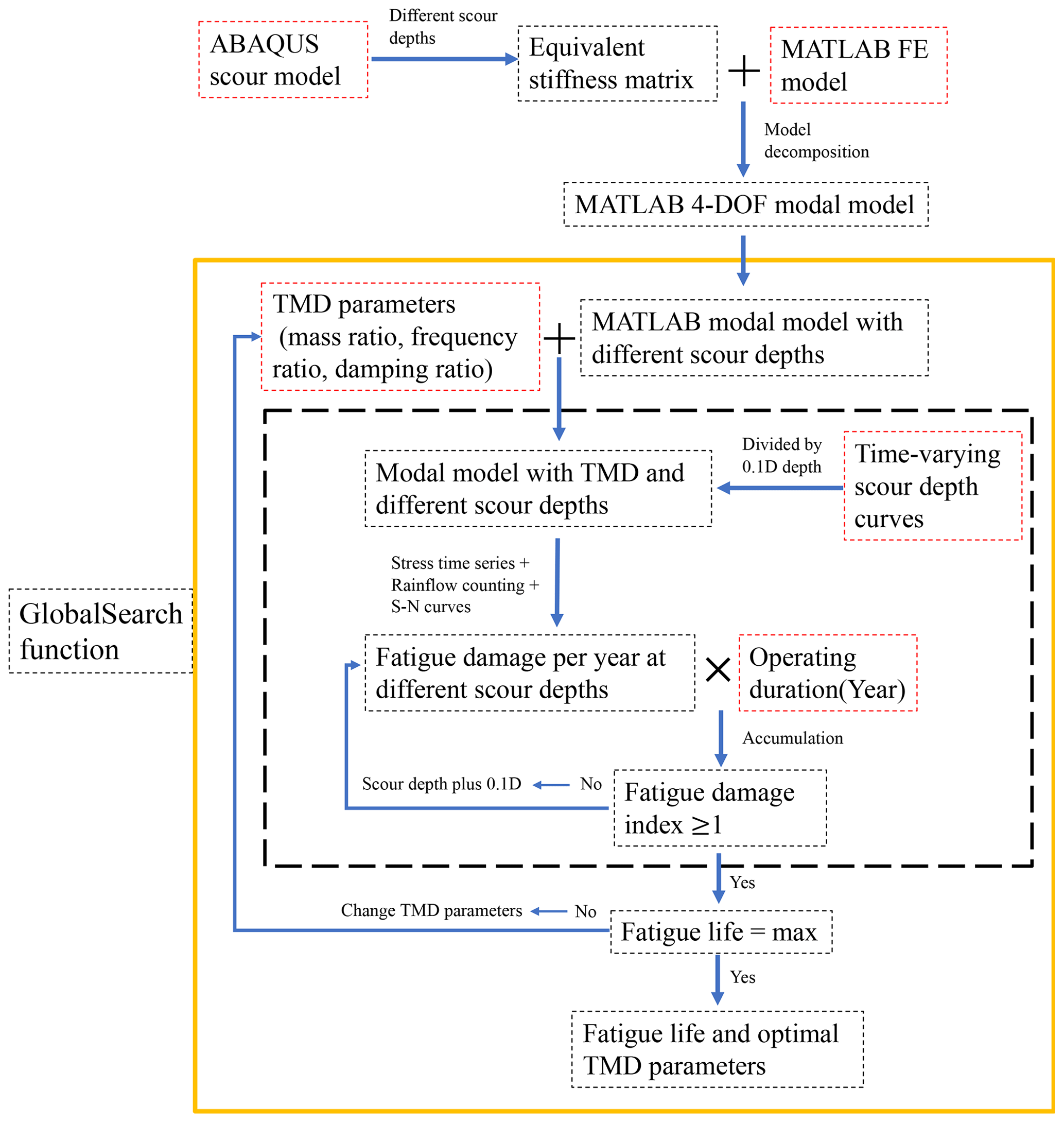
Here, a fatigue-life-based optimization technique (FOT) to find optimal parameters of the TMD is developed in MATLAB, as shown in Fig. 6. In this technique, the frequency ratio, mass ratio, and damping ratio of the TMD are set as the optimal parameters to be searched, with the optimization objective being the fatigue life. When considering the time-varying scour process, the time-varying scour depth curve is first divided into a number of scour depths in increments of 0.1 D. For each scour depth, the fatigue damage is calculated and the total fatigue damage in a particular duration is then summarized. When the scour pit becomes deeper, the fatigue damage accumulates and finally reaches 1, which denotes the end of fatigue life. The simplified 4-DOF modal model incorporating scour modelling is used to generate the stress time series. The optimization problem is formulated to determine the optimal parameters of the TMD that maximize the fatigue life of the OWT support structure. The GlobalSearch function in MATLAB is used to solve the optimization problem. In the TMD optimization process, the mass ratio of the TMD is initially set to 1 %, and only the parameters of the frequency ratio and the damping ratio are optimized. Subsequently, in order to understand the optimization effect of the TMD when the value of the TMD mass ratio is not fixed, a mass ratio optimization interval is provided, making the mass ratio a variable within the optimization range.
4.1 Environmental states and load cases
In this study, fatigue analyses are performed under 22 environmental states provided by van der Tempel (2006), taking into account both operational and parked conditions. These 22 environmental states are shown in Table 4. In operating conditions, the wind turbine withstands the aerodynamic load of the rotating rotor and the wind load of the tower. The wind load on the rotor is calculated using the BEM theory. In parked conditions, the wind turbine mainly withstands the aerodynamic load on the tower, and the aerodynamic damping is very small. The aerodynamic loading on the blades is calculated by directly looking at the aerodynamic loading coefficient table based on the local attack angles. The wind and wave loads are assumed to always act in the same direction to simplify the analysis. When the mean wind speeds are above the cut-in wind speed and below the cut-out wind speed, a 95 % wind turbine availability is assumed, following the setting in Velarde et al. (2020), meaning that the OWT does not produce power 5 % of the time when the mean wind speeds are in the operating range. For a specific combination of mean wind speed, wave period, and wave height, six different random seed numbers are used to produce various wind fields and wave profiles, minimizing the impact of randomness. To obtain the stress time histories at the mudline, a 700 s simulation is conducted for each random seed, and the response in the first 100 s is subtracted to eliminate the effect of initial transient vibration (Capaldo and Mella, 2023; Stieng and Muskulus, 2020).
Table 4Environmental states, adopted from van der Tempel (2006).
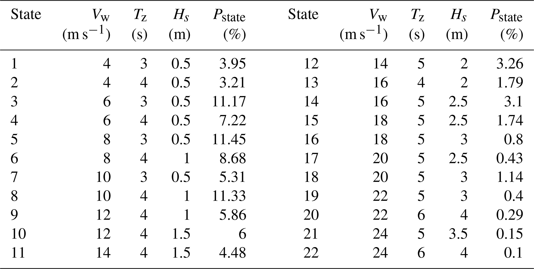
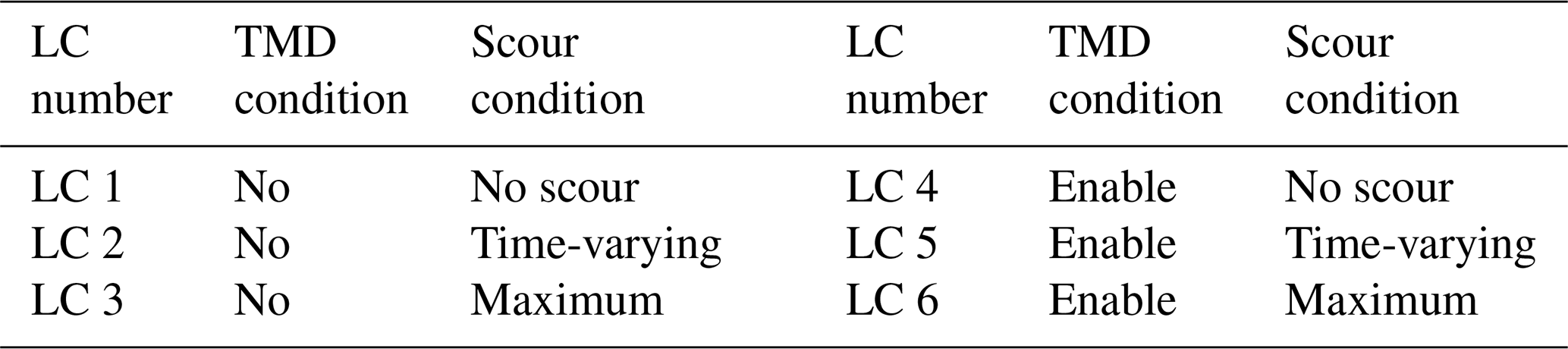
In Table 4, Vw is the wind speed, Tz is the zero-crossing wave period, Hs is the wave height, and Pstate is the probability of environmental state. To investigate the effect of scour and installation of the TMD on the fatigue damage accumulation, six load cases (LCs) are selected, as shown in Table 5. LC 1 is used as the reference case, and other cases are distinguished by different scour and TMD settings. For LC 4 to LC 6, the initial design of the TMD with the mass ratio of 1 % is used.
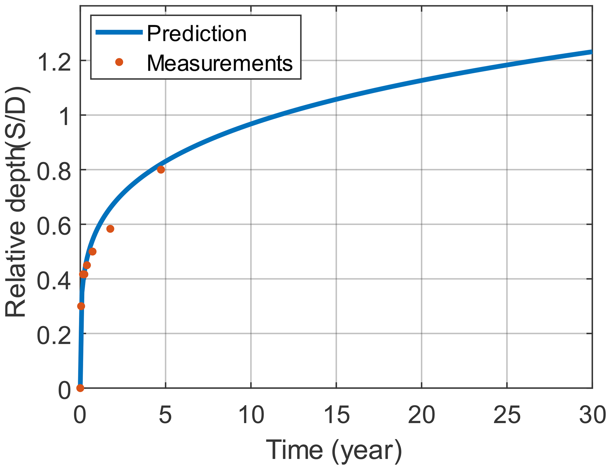
When considering the time-varying scour depth, for a particular time, t, the time-varying scour depth S can be predicted by the equation provided by Nakagawa and Suzuki (1976):
where D is the diameter of the monopile and t1 is the reference time and can be calculated by
The variable u is the tidal velocity and taken as 0.5 m s−1, uc is the critical shear velocity and taken as 0.37 m s−1, g is the acceleration of gravity and taken as 9.8 m s−2, and d50 is the grain size of sea sand and taken as 0.2 mm. The parameter , where ρs is the density of sand and taken as 2.65 g cm−3 and ρw is the density of water and taken as 1 g cm−3. Rudolph et al. (2004) provided information on the sea state and measured the scour depth in the North Sea where the monopile N7 is situated. The measured scour depth was fitted well for the first 5 years based on the time-varying scour depth prediction equation shown in Eq. (13). As shown in Fig. 7, the data from the North Sea site can represent a typical ocean environment with time-varying scour and are used for the correlation analysis in this study.
When conducting an analysis with the time-varying scour, an increment of scour depth equal to 0.1 D is utilized. At a specific scour depth, the fatigue damage is calculated, and the total fatigue damage during a longer period with varying scour depths can then be obtained by damage accumulation. According to the specification by DNV, the maximum depth of a local scour pit formed around a pile foundation is 1.3 times the diameter of the pile. Therefore, it is assumed that the local scour pit has a maximum scour depth of 1.3 D, at which the scour process achieves equilibrium.
4.2 Scour influence on natural frequencies
The scour of the soil around the monopile has an important effect on the natural frequencies of the OWT. For different scour depths, the first natural frequencies obtained by the models in Abaqus and MATLAB are compared in Fig. 8. The figure shows that the increase in the scour depth leads to a decrease in the first natural frequency of the OWT. The first natural frequency is 0.265 Hz when no scour occurs, and the natural frequency is reduced to 0.248 Hz when the depth of the scour pit reaches the maximum depth. The first natural frequency is reduced by 6.42 % due to the maximum scour depth. It shows that the natural frequency nearly monotonically decreases with the increase in the scour depth. The installation of a TMD also influences the natural frequency of the OWT main structure. The TMD with a mass ratio of 1 % makes the first natural frequency of the OWT main structure reduce to 0.251 Hz when no scour occurs, meaning that the natural frequency is reduced by 5.28 %.

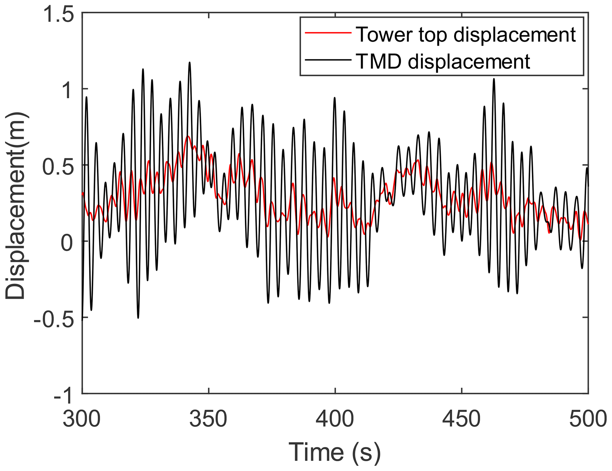
In the TMD design process, the feasible displacement should be considered. The smaller the mass ratio of TMD, the larger the feasible displacement required. The 22nd environmental state corresponds to the greatest vibration responses of the wind turbine tower top due to large wind speed variations and lower aerodynamic damping, and the stroke of the TMD can be the largest. As shown in Fig. 9, the relative displacement between the TMD and the tower top is much smaller than the inner diameter of the wind turbine tower top in the 22nd environmental state. It shows that the stroke of the TMD is sufficient when the mass ratio of the TMD is 1 %.
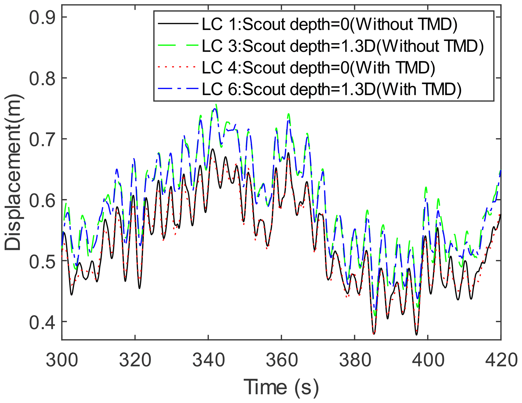
Figure 10Dynamic response of the wind turbine under wind–wave coupled loads for four operating conditions.
4.3 Dynamic response analysis
When the OWT in the operating state is under the ninth environmental state, which corresponds to the rated wind speed of 12 m s−1, a comparison of the tower top displacements is made for LC 1, LC 3, LC 4, and LC 6, as shown in Fig. 10. These displacements are obtained from the FE model in MATLAB described in Sect. 2.1. By comparing the displacements from 300 to 420 s for LC 1 and LC 4, it can be found that the vibration amplitude of the tower top slightly decreases when the TMD is installed. Moreover, by comparing the displacement responses for LC 1 and LC 3, it can be found that the average of the displacement at the tower top increases when the scour depth reaches 1.3 D. This is because scour makes the OWT support structure become more flexible. It is known that the aerodynamic damping is large when the OWT is operating under the rated wind speed, so it is normal that the vibration mitigation effect of the TMD is less significant in this case. The effect of the TMD is more prominent in parked conditions with less aerodynamic damping. As shown in Fig. 11, the vibration mitigation effect of the TMD is more significant in the parked condition with a wind speed of 3 m s−1.
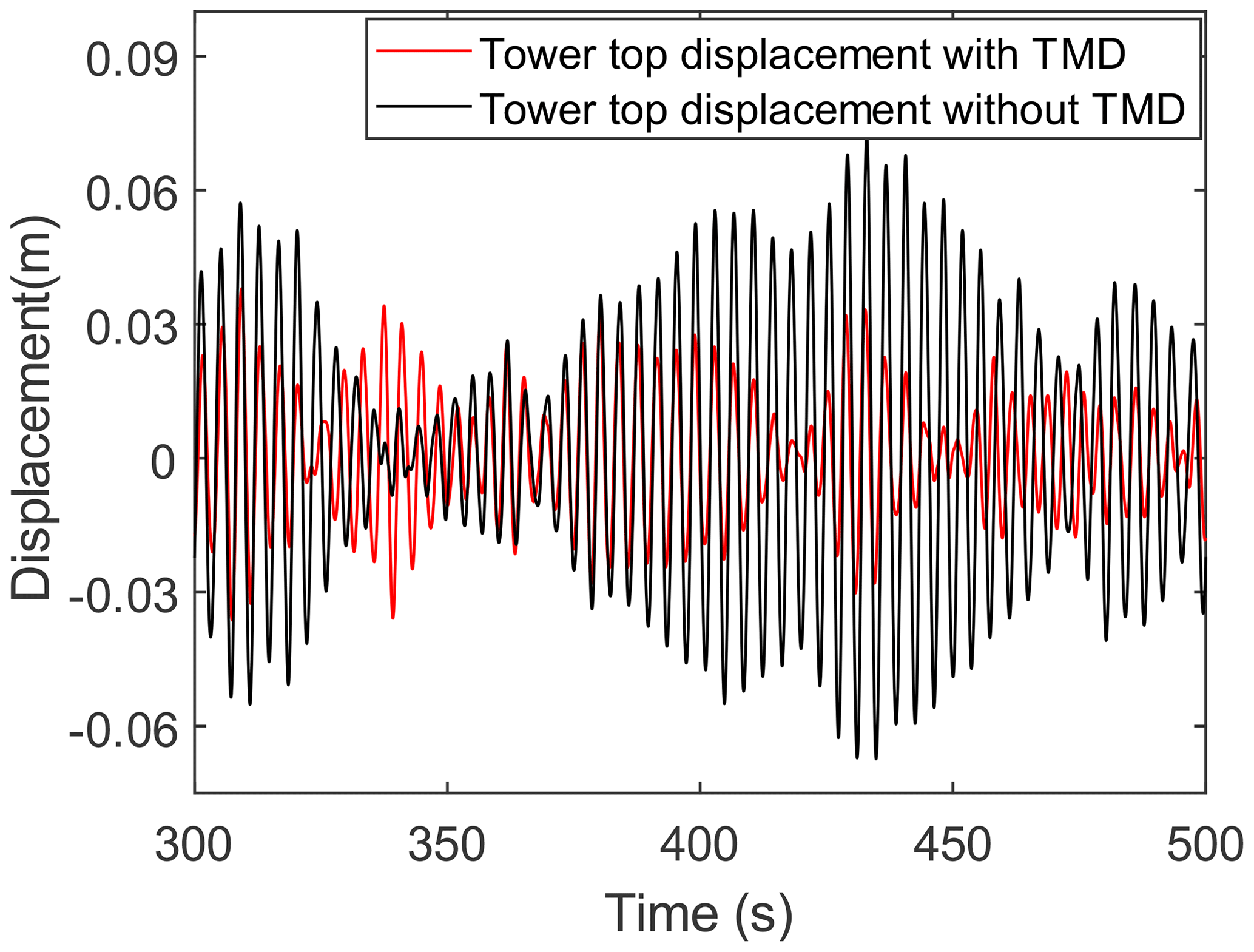
Figure 11The displacement response of the wind turbine tower in the parked condition with a wind speed of 3 m s−1.
4.4 Fatigue calculation results
In Sect. 2.4, it is mentioned that in the process of fatigue life analysis, the 4-DOF simplified modal model is used to greatly decrease the calculation time. The accuracy test of the 4-DOF modal model in generating dynamic responses is first presented in this subsection. Under the turbulent wind field with a turbulence intensity of 11.9 % and an average wind speed of 12 m s−1, the FE model and the 4-DOF simplified modal model are used to calculate the stress responses at the mudline for 10 min.

Figure 12Comparison of stresses at the mudline from the FE model and the 4-DOF model in the time domain (a) and frequency domain (b).
As shown in Fig. 12, the stress responses from these two models are very close, confirming the accuracy of the 4-DOF modal model. The fatigue damage caused by the FE model in 10 min is , and the fatigue damage caused by the 4-DOF model in 10 min is , with an error of 0.05 %. Moreover, the calculation time of the 4-DOF simplified modal model is only about th of that of the FE model, which shows that the 4-DOF simplified modal model is adequate to replace the FE model when conducting the fatigue life prediction.
The 4-DOF simplified modal model is used to conduct the fatigue life prediction for the OWT support structure for LC 1 to LC 6. A 10 min simulation is conducted for each of the six different random seed numbers to obtain stress time histories at the mudline. The location of the hotspot selected to assess fatigue damage is where the maximum stress occurs, specifically in the support structure cross section at the mudline. Although the location in the monopile where the moment reaches its maximum value can be below the mudline, the location at the mudline is chosen for simplicity. Further, since the SSI is modelled in the FE model by an equivalent soil stiffness matrix, it is not straightforward to determine the internal forces at the cross sections below the mudline. Given the stress time series at the selected hotspot, the corresponding fatigue damage is calculated. The fatigue damage for the combination of the mean wind speed, wave period, and wave height over 10 min is calculated by averaging the fatigue damage across six random seeds. For all 22 environment states, the 10 min fatigue damage is calculated. The fatigue life is predicted according to the Palmgren–Miner sum rule by combining these calculated fatigue damage values and the probabilities of the environmental states.

For various scour depths, the fatigue life of the OWT considering both operating and parked conditions is predicted with or without TMD installation, and the results are shown in Fig. 13. It is shown that an increase in scour depth leads to a decrease in fatigue life and that an increasing fatigue life reduction rate can be observed when the scour depth increases. When no scour occurs and the TMD is not installed on the OWT, the OWT's fatigue life is 59.3 years, and the fatigue life drops to 45.0 years when considering the maximum scour depth of 1.3 D. There exist some uncertainties in the fatigue life prediction process due to the generation of a random wind field and wave profile. It should be noted that the predicted fatigue life is much longer than the normally adopted OWTs' design fatigue life of 25–30 years. This can be explained by the following reasons. First, the maximum moment of the OWT support structure is not at the cross section at the mudline where the selected hotspot is located. Second, the complex wind and wave directionality during the OWT's lifetime is simplified, which can influence the fatigue calculation results. Third, many other operational conditions such as start-up and shutdown phases are not considered in this study, which can also impact fatigue damage accumulation. Moreover, the installation of the TMD greatly extends the OWT support structure's fatigue life by 51.8 % when the pile foundation is not scoured.
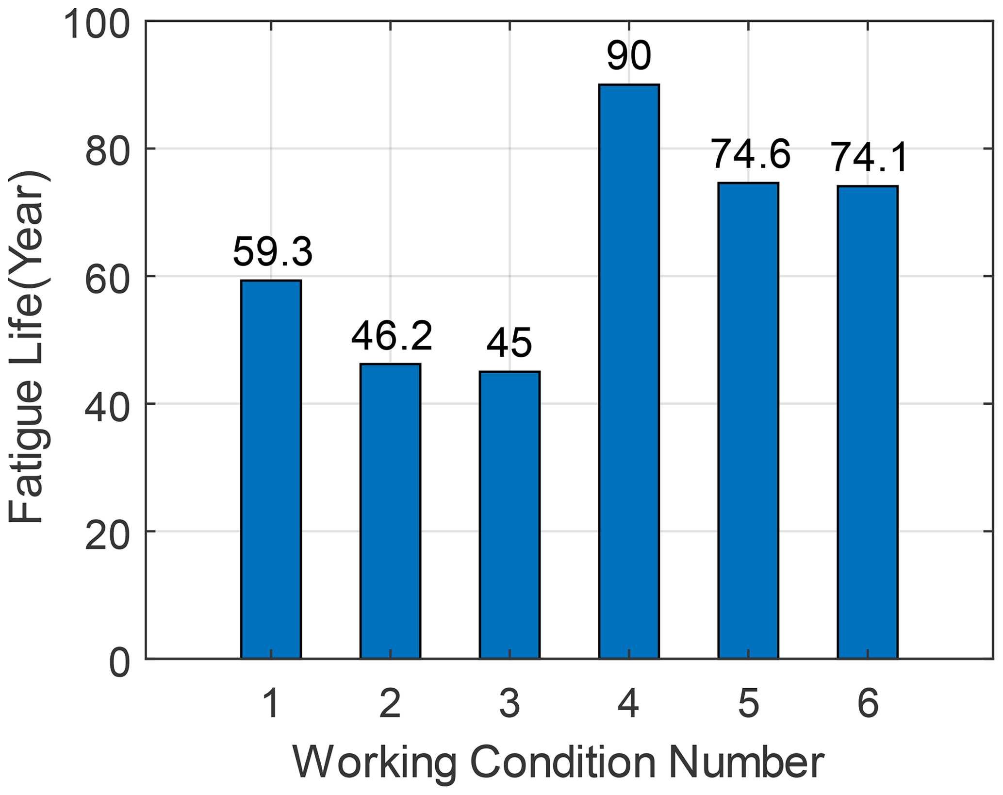
The fatigue life prediction results of the OWT are obtained for all six LCs, as shown in Fig. 14. The fatigue life of the reference case LC 1, which is 59.3 years, is regarded as the reference fatigue life. It shows that the fatigue life decreases by 14.3 years, or about 24.1 %, when the scour depth is set to the maximum value of 1.3 D without applying the TMD compared to the reference fatigue life. When considering the time-varying scour, the fatigue life decreases by about 22.1 % from the reference value. When comparing the results for LC 1 and LC 4, it shows that the installation of the TMD results in a significant increase in the fatigue life of the OWT, with an increase in fatigue life of about 30.7 years, which is about 51.8 %. In LCs with the TMD installed, the fatigue life in LC 6 decreases by about 17.7 % when the scour depth reaches 1.3 D compared to the result for LC 4. But the fatigue life in LC 6 is still 1.25 times the reference fatigue life, which indicates that the imposition of TMD can effectively increase the fatigue life of the OWT by reducing vibration amplitudes.
4.5 Fatigue calculation with optimized TMD
To compare the optimization effect and speed up the optimal parameter search process, the mass ratio of TMD is first kept at 1 %. Before the optimization, the parameter ranges of the frequency ratio and the damping ratio need to be defined. The optimal frequency of the TMD is usually close to the frequency of the main structure, so the range of the frequency ratio is chosen to be from 0.8 to 1.1 for optimization. As the optimal damping ratio can vary in a relatively larger range, the range of the damping ratio for optimization is chosen to be from 1 % to 30 %. The optimization of the TMD is also conducted, with the mass ratio not fixed. A range of the mass ratio from 0.001 to 0.1 is used to optimize the TMD so that the influence of the mass ratio can be evaluated.
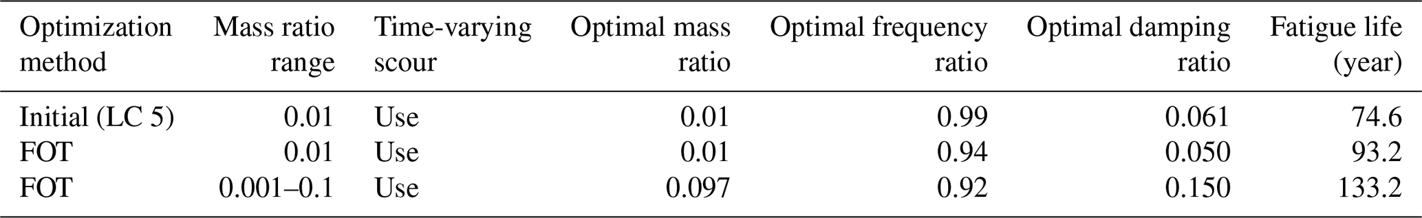
The optimal parameters obtained by FOT and the predicted fatigue life are listed in Table 6. The fatigue life for LC 5 and the parameters of the initially designed TMD are also shown in Table 6 for comparison. It shows that when the mass ratio is fixed at 1 %, the optimal frequency ratio is 0.94, the optimal damping ratio is 5 %, and the final fatigue life is 93.2 years. Compared to the fatigue life with the initially optimized TMD using the traditional method without considering scour, the fatigue life increases by 18.6 years, which is approximately 25 %. It indicates that the parameter search in the optimization process is correct and that it is better to use the TMD parameter search method to design the TMD after obtaining the time-varying scour curve. When the mass ratio range is taken from 0.1 % to 10 %, the optimal mass ratio of the TMD is 9.7 %, the frequency ratio is 0.92, the damping ratio is 15 %, and the final fatigue life is 133.2 years. In this case, the fatigue life of the OWT is significantly longer primarily because of the large mass ratio. However, in practice, it may be uneconomical to implement a TMD with such a large mass ratio.
This study establishes a rapid numerical model that can consider the effect of scour and the installation of a TMD, and the TMD operates only in the FA direction. The model is simplified by concentrated mass instead of RNA and ignores the nonlinearity of the equivalent stiffness matrix. The established model is used to investigate the influence of scour and the installed passive structural control device on the OWT's natural frequencies and fatigue life in 22 environmental states. An optimization technique was also developed to find the optimal parameters of the TMD, considering time-varying scour. Moreover, it shows that the vibration amplitude of the OWT can be effectively reduced by the TMD. On the one hand, the results show that the TMD reduces the vibration amplitude of the tower top. On the other hand, when the scour depth reaches 1.3 D, the wind turbine support structure becomes more flexible, with the displacement of the tower top increasing without TMD.
In addition, the fatigue calculation results show that the installation of the TMD significantly extends the fatigue life of the OWT, but scour can cause a reduced performance of the TMD. It is found that when scour and the scour-induced natural frequency reduction are considered during the OWT's lifetime, the performance of the initially designed TMD is not as good as the TMD optimized by the developed FOT in terms of fatigue life enhancement. Given a mass ratio of 1 %, the fatigue life can be extended by 25 % with the TMD optimized by FOT. This is because the FOT can consider the effect of time-varying scour. This study focuses solely on analysing scour, but it is important to note that other factors, like soil degradation, can also impact the dynamic characteristics of OWTs. These factors may influence on structural control devices and the evaluation of fatigue life. Additionally, during OWTs' lifetime, the properties of installed TMDs can also change, making the evaluation of TMDs' performance and OWTs' fatigue life more complicated. These factors are worth investigating in the future.
The source code is not available in the present study due to commercial constraints.
The data set used in this study is available on the following website: https://api.semanticscholar.org/CorpusID:165155527 (Rudolph et al., 2004).
YC: investigation, software, validation, formal analysis, and writing (original draft). NW: data curation and investigation. JY: validation and software. CC: conceptualization, methodology, writing (review and editing), supervision, and funding acquisition. RZ: methodology and resources. XH: writing (review and editing) and funding acquisition.
The contact author has declared that none of the authors has any competing interests.
Publisher's note: Copernicus Publications remains neutral with regard to jurisdictional claims made in the text, published maps, institutional affiliations, or any other geographical representation in this paper. While Copernicus Publications makes every effort to include appropriate place names, the final responsibility lies with the authors.
The financial support from the National Natural Science Foundation of China (grant no. 52108280), the Yangjiang Offshore Wind Power Laboratory (grant no. YJOWP-OF-2022A10), and the National Science Fund for Distinguished Young Scholars (grant no. 52025082) is greatly appreciated.
This research has been supported by the National Natural Science Foundation of China (grant no. 52108280), the Yangjiang Offshore Wind Power Laboratory (grant no. YJOWP-OF-2022A10), and the National Science Fund for Distinguished Young Scholars (grant no. 52025082).
This paper was edited by Raimund Rolfes and reviewed by two anonymous referees.
Amirafshari, P., Brennan, F., and Kolios, A.: A fracture mechanics framework for optimising design and inspection of offshore wind turbine support structures against fatigue failure, Wind Energ. Sci., 6, 677–699, https://doi.org/10.5194/wes-6-677-2021, 2021.
Aydin, E., Öztürk, B., Kebeli, Y. E., and Gültepe, G.: An Experimental Study on the Effects of Different Pendulum Damper Designs on Structural Behavior, in: Seismic Isolation, Energy Dissipation and Active Vibration Control of Structures, edited by: Cimellaro, G. P., Lecture Notes in Civil Engineering, vol 309, 240–253, https://doi.org/10.1007/978-3-031-21187-4_18, 2023.
Bergua, R., Robertson, A., Jonkman, J., and Platt, A.: Specification Document for OC6 Phase II: Verification of an Advanced Soil-Structure Interaction Model for Offshore Wind Turbines, Golden, CO, National Renewable Energy Laboratory, https://www.nrel.gov/docs/fy21osti/79938.pdf (last access: 23 April 2024), 2021.
Bergua, R., Robertson, A., Jonkman, J., Platt, A., Page, A., Qvist, J., Amet, E., Cai, Z., Han, H., Beardsell, A., Shi, W., Galván, J., Bachynski‐Polić, E., McKinnon, G., Harnois, V., Bonnet, P., Suja‐Thauvin, L., Hansen, A. M., Mendikoa Alonso, I., Aristondo, A., Battistella, T., Guanche, R., Schünemann, P., Pham, T., Trubat, P., Alarcón, D., Haudin, F., Nguyen, M. Q., and Goveas, A.: OC6 Phase II: Integration and verification of a new soil–structure interaction model for offshore wind design, Wind Energy, 25, 793–810, https://doi.org/10.1002/we.2698, 2022.
Branlard, E.: Wind Turbine Aerodynamics and Vorticity-Based Methods: Fundamentals and recent applications, Springer, https://doi.org/10.1007/978-3-319-55164-7, 2017.
Capaldo, M. and Mella, P.: Damping analysis of floating offshore wind turbines (FOWTs): a new control strategy reducing the platform vibrations, Wind Energ. Sci., 8, 1319–1339, https://doi.org/10.5194/wes-8-1319-2023, 2023.
Chen, C. and Duffour, P.: Modelling damping sources in monopile-supported offshore wind turbines, Wind Energy, 21, 1121–1140, https://doi.org/10.1002/we.2218, 2018.
Chen, C., Duffour, P., and Fromme, P.: Modelling wind turbine tower-rotor interaction through an aerodynamic damping matrix, J. Sound Vib., 489, 115667, https://doi.org/10.1016/j.jsv.2020.115667, 2020.
Chen, C., Duffour, P., Dai, K., Wang, Y., and Fromme, P.: Identification of aerodynamic damping matrix for operating wind turbines, Mech. Syst. Signal Pr., 154, 107568, https://doi.org/10.1016/j.ymssp.2020.107568, 2021a.
Chen, C., Duffour, P., Fromme, P., and Hua, X.: Numerically efficient fatigue life prediction of offshore wind turbines using aerodynamic decoupling, Renew. Energ., 178, 1421–1434, https://doi.org/10.1016/j.renene.2021.06.115, 2021b.
Colwell, S. and Basu, B.: Tuned liquid column dampers in offshore wind turbines for structural control, Eng. Struct., 31, 358–368, https://doi.org/10.1016/j.engstruct.2008.09.001, 2009.
Dai, K., Huang, H., Lu, Y., Meng, J., Mao, Z., and Camara, A.: Effects of soil–structure interaction on the design of tuned mass damper to control the seismic response of wind turbine towers with gravity base, Wind Energy, 24, 323–344, https://doi.org/10.1002/we.2576, 2021.
Dai, S., Han, B., Wang, B., Luo, J., and He, B.: Influence of soil scour on lateral behavior of large-diameter offshore wind-turbine monopile and corresponding scour monitoring method, Ocean Eng., 239, 109809, https://doi.org/10.1016/j.oceaneng.2021.109809, 2021.
Den Hartog, J. P.: Mechanical Vibrations. Fourth Edition, J. Roy. Aeronaut. Soc., 61, 139–139, https://doi.org/10.1017/S0368393100131049, 1957.
Dinh, V.-N. and Basu, B.: Passive control of floating offshore wind turbine nacelle and spar vibrations by multiple tuned mass dampers, Struct. Control Hlth., 22, 152–176, https://doi.org/10.1002/stc.1666, 2015.
Det Norske Veritas AS: RP-C203: Fatigue design of offshore steel structures, DNVGL-RP-0005, http://www.dnvgl.com (last access: 23 April 2024), 2014a.
Det Norske Veritas AS: Design of Offshore Wind Turbine Structures, DNV-OS-J101, http://www.dnv.com (last access: 23 April 2024), 2014b.
Fard, M. M., Erken, A., Erkmen, B., and Ansal, A.: Analysis of Offshore Wind Turbine by considering Soil-Pile-Structure Interaction: Effects of Foundation and Sea-Wave Properties, J. Earthquake Eng., 26, 7222–7244, https://doi.org/10.1080/13632469.2021.1961936, 2022.
Hasselmann, K. F., Barnett, T. P., Bouws, E., Carlson, H., Cartwright, D. E., Enke, K., Ewing, J. A., Gienapp, H., Hasselmann, D. E., Kruseman, P., Meerburg, A., Müller, P., Olbers, D. J., Richter, K., Sell, W., and Walden, H.: Measurements of wind-wave growth and swell decay during the joint North Sea wave project (JONSWAP), Environmental Science, https://hdl.handle.net/21.11116/0000-0007-DD3C-E (last access: 23 April 2024), 1973.
International Electrotechnical Commission: Wind energy generation systems Part 3-1: Design requirements for fixed offshore wind turbines, IEC 61400-3-1:2019-04(en), https://www.iec.ch/ (last access: 23 April 2024), 2019.
Jonkman, B. J. and Buhl, M. L.: TurbSim User's Guide, National Renewable Energy Laboratory, Technical Report, 500, 39797, http://www.osti.gov/bridge (last access: 23 April 2024), 2006.
Jonkman, J., Butterfield, S., Musial, W., and Scott, G.: Definition of a 5-MW Reference Wind Turbine for Offshore System Development, National Renewable Energy Laboratory, NREL/TP-500-38060, http://www.osti.gov/bridge (last access: 23 April 2024), 2009.
Jung, S., Kim, S.-R., Patil, A., and Hung, L. C.: Effect of monopile foundation modeling on the structural response of a 5-MW offshore wind turbine tower, Ocean Eng., 109, 479–488, https://doi.org/10.1016/j.oceaneng.2015.09.033, 2015.
Lackner, M. A. and Rotea, M. A.: Passive structural control of offshore wind turbines, Wind Energy, 14, 373–388, https://doi.org/10.1002/we.426, 2011a.
Lackner, M. A. and Rotea, M. A: Structural control of floating wind turbines, Mechatronics, 21, 704–719, https://doi.org/10.1016/j.mechatronics.2010.11.007, 2011b.
Liang, F., Chen, H., and Jia, Y.: Quasi-static p-y hysteresis loop for cyclic lateral response of pile foundations in offshore platforms, Ocean Eng., 148, 62–74, https://doi.org/10.1016/j.oceaneng.2017.11.024, 2018.
Lu, D., Wang, W., and Li, X.: Experimental study of structural vibration control of 10-MW jacket offshore wind turbines using tuned mass damper under wind and wave loads, Ocean Eng., 288, 116015, https://doi.org/10.1016/j.oceaneng.2023.116015, 2023.
Ma, H. and Chen, C.: Scour protection assessment of monopile foundation design for offshore wind turbines, Ocean Eng., 231, 109083, https://doi.org/10.1016/j.oceaneng.2021.109083, 2021.
Mayall, R. O., McAdam, R. A., Byrne, B. W., Burd, H. J., Sheil, B. B., Cassie, P., and Whitehouse, R. J. S.: Experimental modelling of the effects of scour on offshore wind turbine monopile foundations, in: Physical Modelling in Geotechnics, edited by: McNamara, A., Divall, S., Goodey, R., Taylor, N., Stallebrass, S., and Panchal, J., 725–730, https://doi.org/10.1201/9780429438660-109, 2018.
Nakagawa, H. and Suzuki, K.: Local Scour Around Bridge Pier in Tidal Current, Coast. Eng. Jpn., 19, 89–100, https://doi.org/10.1080/05785634.1976.11924219, 1976.
Pedersen, D. M. and Askheim, H.: Implementation of seismic soil-structure interaction in OpenFAST and application to a 10 MW offshore wind turbine on jacket structure, Norwegian University, https://hdl.handle.net/11250/2824677 (last access: 23 April 2024), 2021.
Pelayo, F., Skafte, A., Aenlle, M. L., and Brincker, R.: Modal Analysis Based Stress Estimation for Structural Elements Subjected to Operational Dynamic Loadings, Exp. Mech., 55, 1791–1802, https://doi.org/10.1007/s11340-015-0073-6, 2015.
Rezaei, R.: Fatigue Sensitivity of Monopile-supported Offshore Wind Turbines, PhD thesis, University College London, https://discovery.ucl.ac.uk/id/eprint/1566914 (last access: 23 April 2024), 2017.
Rezaei, R., Duffour, P., and Fromme, P.: Scour influence on the fatigue life of operational monopile-supported offshore wind turbines, Wind Energy, 21, 683–696, https://doi.org/10.1002/we.2187, 2018.
Rudolph, D., Bos, K. J., Luijendijk, A. P., and Rietema, K.: Scour around offshore structures-analysis of field measurements, Semantis Scholar [data set], https://api.semanticscholar.org/CorpusID:165155527 (last access: 23 April 2024), 2004.
Shahmohammadi, A. and Shabakhty, N.: Pile Apparent Fixity Length Estimation for the Jacket-type Offshore Wind Turbines under Lateral Loads Applicable to Fatigue Analysis, Int. J. Coast. Offshore Eng., 3, 25–33, https://doi.org/10.29252/ijcoe.3.4.25, 2020.
Shirzadeh, R., Devriendt, C., Bidakhvidi, M. A., and Guillaume, P.: Experimental and computational damping estimation of an offshore wind turbine on a monopile foundation, J. Wind Eng. Ind. Aerod., 120, 96–106, https://doi.org/10.1016/j.jweia.2013.07.004, 2013.
Song, J. and Achmus, M.: Cyclic overlay model of p–y curves for laterally loaded monopiles in cohesionless soil, Wind Energ. Sci., 8, 327–339, https://doi.org/10.5194/wes-8-327-2023, 2023.
Sørensen, P. H. S. and Ibsen, L. B.: Assessment of foundation design for offshore monopiles unprotected against scour, Ocean Eng., 63, 17–25, https://doi.org/10.1016/j.oceaneng.2013.01.016, 2013.
Stieng, L. E. S. and Muskulus, M.: Reliability-based design optimization of offshore wind turbine support structures using analytical sensitivities and factorized uncertainty modeling, Wind Energ. Sci., 5, 171–198, https://doi.org/10.5194/wes-5-171-2020, 2020.
Tang, Z., Melville, B., Shamseldin, A., Guan, D., Singhal, N., and Yao, Z.: Experimental study of collar protection for local scour reduction around offshore wind turbine monopile foundations, Coast. Eng., 183, 104324, https://doi.org/10.1016/j.coastaleng.2023.104324, 2023.
van der Tempel, J.: Design of support structures for offshore wind turbines, PhD thesis, Technische Universiteit Delft, http://resolver.tudelft.nl/uuid:ae69666e-3190-4b22-84ed-2ed44c23e670 (last access: 23 April 2024), 2006.
Velarde, J., Kramhøft, C., Sørensen, J. D., and Zorzi, G.: Fatigue reliability of large monopiles for offshore wind turbines, Int. J. Fatigue, 134, 105487, https://doi.org/10.1016/j.ijfatigue.2020.105487, 2020.
Wang, G., Xu, S., Zhang, Q., and Zhang, J.: An experimental study of the local scour protection methods around the monopile foundation of offshore wind turbines, Ocean Eng., 273, 113957, https://doi.org/10.1016/j.oceaneng.2023.113957, 2023.
Wang, L., Zhou, W., Guo, Z., and Rui, S.: Frequency change and accumulated inclination of offshore wind turbine jacket structure with piles in sand under cyclic loadings, Ocean Eng., 217, 108045, https://doi.org/10.1016/j.oceaneng.2020.108045, 2020.
Wang, X., Zeng, X., Li, X., and Li, J.: Investigation on offshore wind turbine with an innovative hybrid monopile foundation: An experimental based study, Renew. Energ., 132, 129–141, https://doi.org/10.1016/j.renene.2018.07.127, 2019.
Zdravković, L., Taborda, D., Potts, D., Jardine, R., Sideri, M., Schroeder, F., Byrne, B., McAdam, R., Burd, H., Houlsby, G., Martin, C., Gavin, K., Doherty, P., Igoe, D., Wood, A., Kallehave, D., and Gretlund, J.: Numerical modelling of large diameter piles under lateral loading for offshore wind applications, Third International Symposium on Frontiers in Offshore Geotechnics, Oslo Norway, 10 June 2015, ISFOG 2015, https://api.semanticscholar.org/CorpusID:114770992 (last access: 30 April 2024), 2015.
Zhang, F., Chen, X., Feng, T., Wang, Y., Liu, X., and Liu, X.: Experimental study of grouting protection against local scouring of monopile foundations for offshore wind turbines, Ocean Eng., 258, 111798, https://doi.org/10.1016/j.oceaneng.2022.111798, 2022.
Zhang, F., Chen, X., Yan, J., and Gao, X.: Countermeasures for local scour around offshore wind turbine monopile foundations: A review, Appl. Ocean Res., 141, 103764, https://doi.org/10.1016/j.apor.2023.103764, 2023.
Zhang, H., Liang, F., and Zheng, H.: Dynamic impedance of monopiles for offshore wind turbines considering scour-hole dimensions. Appl, Ocean Res., 107, 102493, https://doi.org/10.1016/j.apor.2020.102493, 2021.
Zhang, R., Zhao, Z., and Dai, K.: Seismic response mitigation of a wind turbine tower using a tuned parallel inerter mass system, Eng. Struct., 180, 29–39, https://doi.org/10.1016/j.engstruct.2018.11.020, 2019.