the Creative Commons Attribution 4.0 License.
the Creative Commons Attribution 4.0 License.
 | 27 Jun 2025
A small-scale and autonomous testbed for three-line delta kites applied to airborne wind energy
Francisco DeLosRíos-Navarrete
Jorge González-García
Iván Castro-Fernández
Gonzalo Sánchez-Arriaga
A mechanical control system and the guidance and control modules of a small-scale and autonomous testbed for three-line kites applied to airborne wind energy are presented. It extends the capabilities of a previously developed infrastructure by (i) changing the actuation system to add a third tether to control the kite pitch angle, (ii) adding running-line tensiometers to measure the three tether tensions while allowing tether reel-in and reel-out and onboard load cells to measure the bridle tensions, and (iii) providing a real-time control system to operate the kite autonomously in figure-eight trajectories. A controller based on a hybrid guidance scheme for figure-eight flight paths, which combines attractor points for the straight segments and a continuous heading angle tracking for the turns, was implemented and validated in an experimental campaign. Two flights of the campaign were used to illustrate the performance of the controller and its capability to adjust the lateral amplitude, elevation, and radius of the turns by varying a few parameters of the guidance module. The proposed control scheme was proven effective in achieving satisfactory and repeatable figure-eight paths. The experimental data collected during the autonomous flight were used to investigate the dynamics and control of the kite and the tethers. A correlation between the heading and roll angles of the kite was identified and modeled with a simple analytical law with empirical coefficients. Similarly to previous works on airborne wind energy, a linear relation between the derivative of the course angle and the steering input was found. The analysis of the on-ground tensiometers and the onboard load cells revealed a variable time delay of up to 0.2 s between both measurements. The work shows that the testbed and its instruments are suitable for investigating the effect of tether sagging and for developing and testing controllers for airborne wind energy systems.
- Article
(3059 KB) - Full-text XML
- BibTeX
- EndNote


The availability of wind resources is a determining factor for the economic viability of wind energy power sources (Coca-Tagarro, 2023). When compared to traditional wind turbines, airborne wind energy (AWE) systems can increase the availability of the fifth percentile wind power density by a factor of 2 over most of Europe (Bechtle et al., 2019). Despite its potential, AWE systems face a particular set of challenges due to their nature as autonomous flying devices with operational areas expanding hundreds of meters from the ground station. Safety and reliability have been identified as some of the main concerns affecting the social acceptance of the technology (Schmidt et al., 2022). Consequently, the aerodynamic characterization of kites and the experimental validation of control algorithms are key for the deployment of the technology, and most AWE companies are currently focused on the long-term and repeatable operation of the machines (Kitemill, 2023; Kitekraft, 2023). The recent measurement of the SkySails PN-14 system power curve, based upon the IEC 61400-12-1 standard (Bartsch et al., 2024), is an important milestone for AWE.
A large number of works have presented experimental results of AWE systems or their fundamental components in the past. A number of approaches to experimental testing can be found in the literature. In-lab testing facilities have been successfully used to gather data from scaled models, often based on water channel setups for improved dynamic similarity (Cobb et al., 2018) or specialized in takeoff and landing (Azaki et al., 2023). Tow tests, in which a kite is attached to a moving vehicle to emulate wind flow, have also been extensively used (Wood et al., 2017; Hummel et al., 2019), with some examples aimed at kite performance measurements predating most works on AWE (Alexander and Stevenson, 2001). Nonetheless, a great number of research groups have focused on the development of ground-fixed prototypes for field tests in a plethora of configurations, often in close collaboration with AWE companies. Some experimental setups have been developed for conducting research on specific topics, like kite aerodynamic characterization (Borobia-Moreno et al., 2021) or autonomous takeoff and landing (Fagiano et al., 2022), while others are multipurpose rigs used for aerodynamic characterization (Oehler and Schmehl, 2019) and guidance and control research (Ahrens et al., 2013), among other topics.
A pillar of many of the previously mentioned experimental setups is to study and validate guidance and control strategies for the autonomous flight of AWE systems. A common approach is to steer the kite along a prescribed trajectory (Diwale et al., 2017; Wood et al., 2015). One of its main advantages is that the target trajectory can be obtained in a separate theoretical optimization analysis based on the maximization of the generated power. An alternative guidance and control approach is the one based on attractor points; i.e., the kite is guided towards a reduced number of waypoints that are sequentially switched to follow a lemniscate path. This strategy is very simple, and it has been validated in several experimental setups using leading-edge inflatable kites, both ground actuated (Fagiano et al., 2014) and fly actuated (Fechner and Schmehl, 2016). Moreover, the shape of the trajectory can be tuned by modifying a small set of intuitive parameters, like the number and position of the waypoints. In our work, we combined such a guidance strategy with a proportional–derivative control to prepare an algorithm with a low computational cost and free of a dynamic model. To the best of the authors' knowledge, there are no examples in the literature of the experimental use of this strategy on three-line rigid-framed delta kites. Rigid wings are particularly interesting for AWE applications due to some aerodynamic advantages as compared to leading-edge inflatable or foil kites (Cherubini et al., 2015). Rigid wings, however, present some drawbacks, like their inferior robustness to impacts during takeoff and landing, and they pose challenges to achieving robust control due to their highly dynamic response. The AWE machine of EnerKíte GmBH (Bormann et al., 2013; Candade et al., 2020) is a practical example of the potential application of the control strategy to three-line delta wings studied in this work.
This study on the autonomous control of a rigid-framed delta kite was conducted by first improving the capabilities of the automatic ground station of Universidad Carlos III de Madrid (Castro-Fernández et al., 2023) and then performing several test campaigns. As explained in Sect. 2, a new configuration of the control system was proposed, and a second linear actuator was added to allow for pitching control of the kite. The amount and quality of the scientific data that can be collected by the testbed were also improved by adding more sensors. For instance, onboard load cells used to measure the tether tensions directly applied to the kite were included. A hybrid guidance strategy is proposed in Sect. 3. Based on a controller, it uses attractor points for the straight segments of the figure-eight path and continuous angle tracking for the curved segments. The results of two flight tests of an experimental campaign, including a 5 min autonomous flight, are presented and discussed in Sect. 4. Finally, the conclusions are presented in Sect. 5.
2.1 System architecture
As shown in Fig. 1a, the proposed system is composed of a ground control unit (GCU) and a rigid-framed delta (RFD) kite equipped with onboard sensor hardware. The RFD kite's design is based on the HQ Kites™ Fazer XXL model and is connected to the GCU by a set of three Dyneema® tethers, routed through a system of pulleys to a common winch mechanism (see Fig. 1b). The drum is fitted with a 3D-printed grooved sleeve to passively guide the tethers during winding. A set of intermediate linear actuators allows for the independent control of the lengths of the left and right tethers (hereafter called the control lines). Both the control lines and the central tether pass through independent running-line tensiometers, equipped with load cells to measure tether tensions even if the winch mechanism is actuated. All elements are fixed to a common aluminum base plate through an assortment of aluminum and steel supports, some of which are equipped with quick-connect mechanisms to facilitate transportation and maintenance. The specifications of the linear actuators, servomotors, and winch motor are as described in Castro-Fernández et al. (2023). The powertrain has been upgraded, incorporating a gearbox with a reduction ratio of 20:1 and a winch radius of 49 mm.
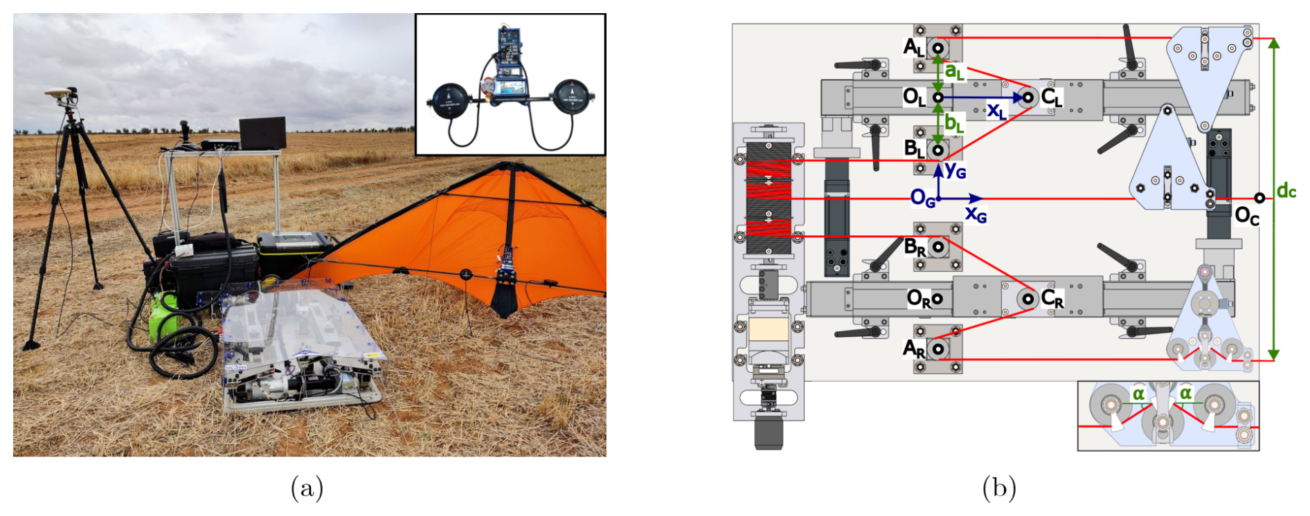
Figure 1(a) The GCU and the RFD kite. The inset shows the onboard electronics. (b) Diagram of the GCU, highlighting the tether's path, the ground reference frame (denoted by subscript G), and several geometric points. One tensiometer cover was removed to show its internal mechanism. The inset shows the definition of the tether angle α.
Figure 2 shows a block diagram of the elements used in the GCU and the RFD kite. Green, blue, orange, and gray colors are used to denote sensors, active signal-processing components, actuators, and human–machine interfaces, respectively. Dashed and dashed–dotted lines are used to denote wired and wireless connections between elements, while mechanical links are shown with solid lines. The next subsections explain each of these building blocks in detail.
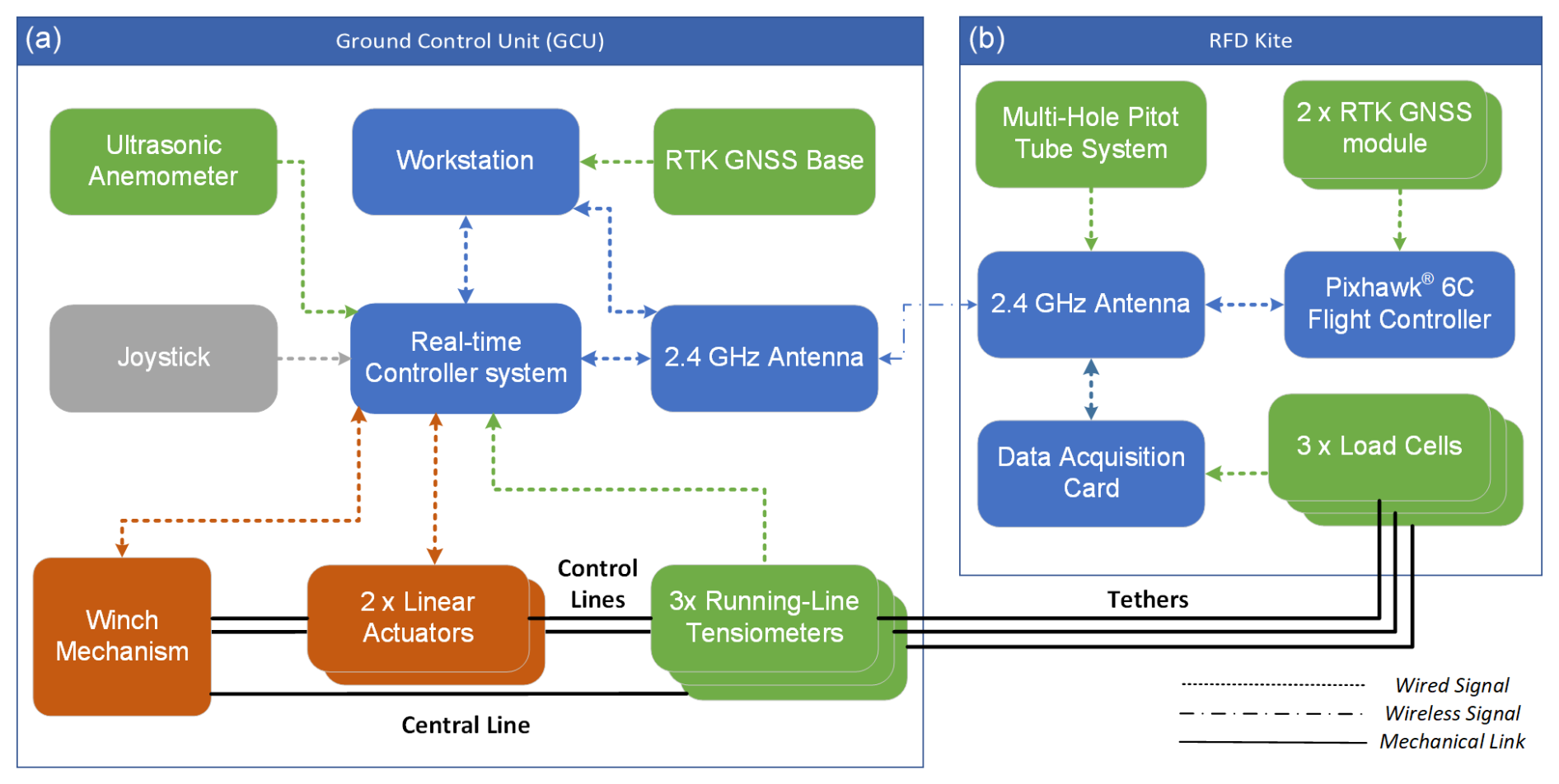
Figure 2Sensors (green), active signal-processing components (blue), actuators (orange), and human–machine interfaces (gray) of the GCU (a) and the kite (b).
2.2 Mechanical control system
Control over the steering and pitch angle of the RFD kite is provided by the proposed control system through the coordinated movement of the linear actuators. Some frames of reference and geometric characteristics should be introduced to understand the principles of actuation of the system. As shown in panel (b) of Fig. 1, we refer to CL and CR as the points where the pulleys of the left and right linear actuators are placed. At points OL and OR, the pulleys of the left and right actuators reach their minimal distances to the winch. A frame of reference SG is introduced, with origin OG located at the intersection between the central tether and the virtual line that passes through points OL and OR, with xG pointing downwind and zG pointing upwards. The displacement of the linear actuators is given by the coordinates xL and xR of points CL and CR, respectively. The origin of the controller's spherical frame of reference, defined in Sect. 3, is given by OC, which is placed at the intersection between the xG axis and the edge of the GCU. Two important design parameters that define the geometry of the control system are
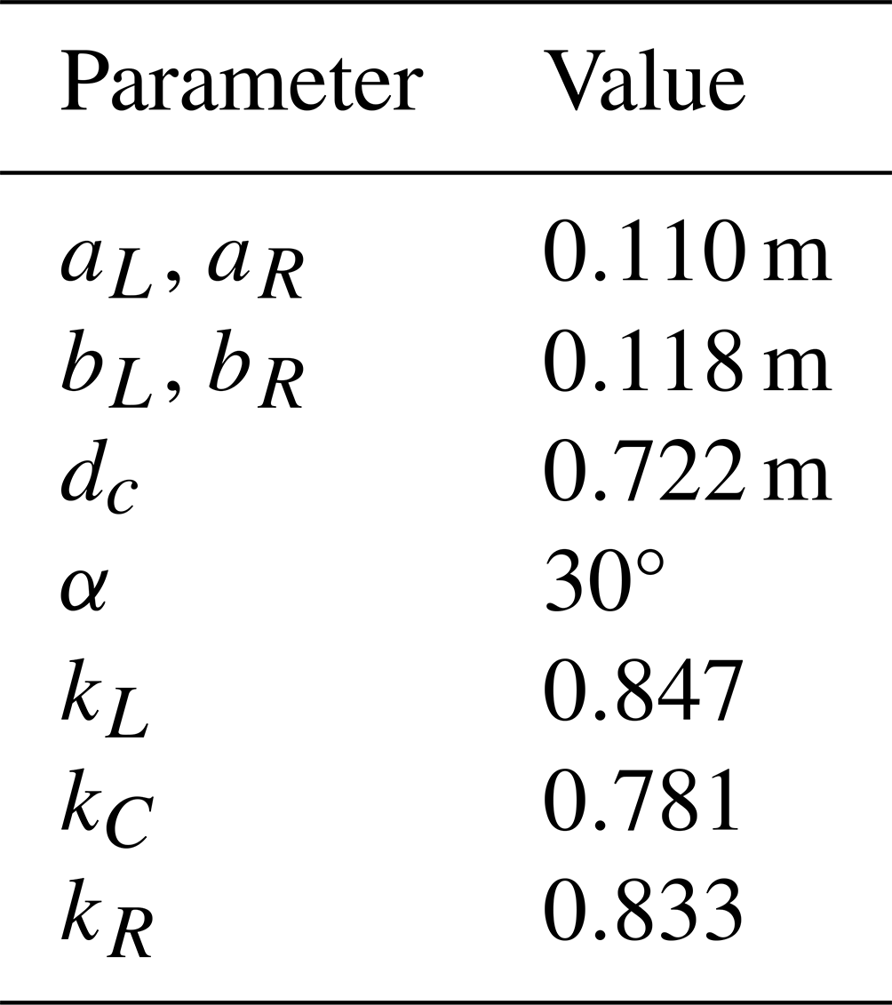
which are the distances between points OL (or OR) and points AL and BL (or AR and BR) where two auxiliary pulleys are located. The control is able to steer the kite because the displacement of the linear actuators xj produces a variation in tether length . The variation in the distance with respect to the reference state without actuator displacement is
For later use, it is convenient to write the actuator displacements xj as a function of the tether length variation Δℓj. From Eq. (2) one finds
Both actuators share a common neutral position x0, defined as the place of the pulley where the carriages rest when no steering input is commanded. The neutral position x0 is initially defined at the middle of the actuator's physical range and can be dynamically adjusted during the flight to control the pitch angle of the RFD kite. When x0 is changed, the distance between the kite's control anchoring points and the ground station is modified, while the distance to the central anchor point remains unchanged, consequently inducing a pitch on the kite.
Kite steering is achieved through the control input ΔLu, defined as the difference in length between the control tethers outside the GCU (LR−LL), which coincides with the tether length difference inside the GCU. Therefore, one has
The proposed scheme uses variable x0 to control the pitch of the kite and ΔLu to steer it. Such an approach is convenient because each control input is in charge of commanding a different degree of freedom of the kite. For given values of x0 and ΔLu, one first finds the quantities
and their substitution in Eq. (3) provides the displacements of the actuators.
2.3 On-ground tensiometers and onboard load cells
The GCU has three running-line tensiometers. These devices provide an indirect measurement of the tether tension while simultaneously allowing for reel-in and reel-out. As shown in Fig. 1b, the tether is routed through a set of three pulleys inside the tensiometer, two of which are fixed, while the central one is connected to the load cell with a rigid link. The contact surface between the link and the chassis of the tensiometer restricts the movement of the pulley to the direction perpendicular to the tether. The traction forces measured by the load cells are
where Tj is the tether tension, and α is the entry and exit angle of the tether, shown in the inset of Fig. 1b. The empirical and dimensionless factor k takes into account the internal friction of the tensiometer that appears in the pulleys and between the mobile pulley and the structure. Factor k was calibrated for each tensiometer with a static load test in which a tether was fixed to an independent load cell on one side and to a set of known loads on the other. Table 1 shows the measured values of k for the three tensiometers and the geometrical parameters of the GCU appearing in Eq. (2).
The three tensiometers located at the GCU measure the tether tension on the ground. However, since the tether is subjected to acceleration and other forces like gravity and the aerodynamic force, the tether tensions at the kite are different. For this reason, three small load cells were added on board the kite. Unlike the tensiometers of the GCU, which needs to be compatible with tether reel-in and reel-out, the onboard load cells were directly located between the tether tip and the bridles. Having knowledge of the tether tensions both on the ground and at the kite opens the possibility of investigating some interesting topics, like the impact of aerodynamic load on the tether dynamics, and also provides useful data to validate tether models in AWE simulators.
2.4 Electronic system architecture
As shown in Fig. 2, the RFD kite is equipped with a Pixhawk® 6C flight controller, used for logging the kite kinematic state. The controller fuses the measurements from its embedded IMU, magnetometer, and barometers with the reading from the RTK GNSS modules in a built-in Kalman filter. A custom-made data acquisition board samples the signals coming from the onboard load cells at regular intervals. A multi-hole pitot tube system, such as the one used in Borobia-Moreno et al. (2021), can also be integrated into the platform to gather data for aerodynamic analysis, although it was not incorporated for this flight campaign as it was not the focus of this work. All onboard electronics are powered by a 7.4 V LiPo battery and a 5 V DC/DC converter. A communication link with the GCU is made with a pair of 2.4 GHz antennas.
The GCU's main control board is based on the Texas Instruments™ F28379D real-time microcontroller. The built-in CAN bus transceiver is used to communicate with both linear actuator servomotors and the winch mechanism motor controller. Measurements from the ultrasonic wind station and the running-line tensiometers are also logged in real time. A joystick is present to provide manual control during takeoff and landing maneuvers, adjust the controller parameters, and set open- or close-loop control as desired by the operator. A workstation is used to log all data gathered by the control board and to broadcast RTK data from the GNSS base station. The power for the GCU is supplied by two 12 V lead-acid batteries connected in series.
The proposed controller uses three angles, which are represented in Fig. 3. Two of them, λ and δ, are the elevation and azimuth of the position vector r, which has its origin at point OC of the GCU and its tip at the center of mass OK of the kite. It reads
where iG, jG, and kG are the unit vectors of the SG frame, and r is the distance between point OC and the center of mass of the kite. Therefore, λ is the elevation angle with respect to the ground, and δ measures the lateral displacement of OK with respect to the xG−zG plane. The third angle used by the controller is the heading angle ψ, which is defined as
where iK is the unit vector along the direction defined by the spine of the RFD kite, and vectors uδ and uλ are defined by the last equality in Eq. (8). The heading angle is measured on the tangent plane defined by the meridian (uλ) and parallel (uδ) unit vectors using as reference the vector iK defined by the kite's spine. Since ψ is the angle between a meridian and the xG axis of the kite, ψ vanishes when the kite points towards the north pole of the sphere in Fig. 3.
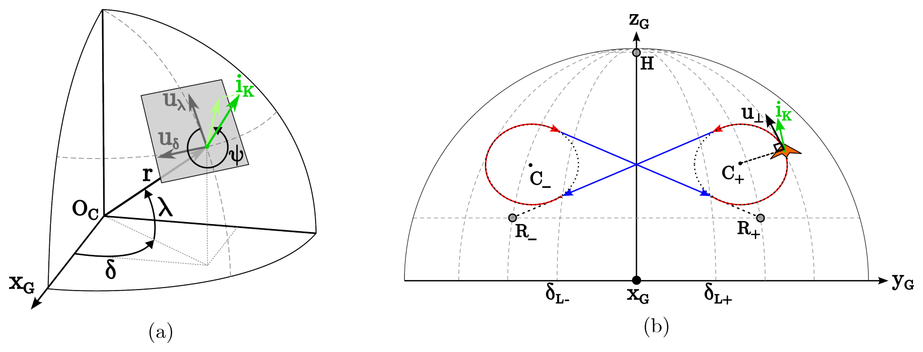
Figure 3(a) Elevation (λ), azimuth (δ), and heading (ψ) angles of the RFD kite. (b) The reference figure-eight trajectory of the kite, which is divided into two downwards straight segments (blue) targeting a reference point (R±) and two upwards turning segments (red) circling a reference center (C±). The reference point H for the hovering mode, the transition limits , and the auxiliary vector u⟂ perpendicular to the turning radius are also shown.
As shown in Fig. 3b, the figure-eight path is divided into two straight segments and two turning sections. Each straight segment is defined by a reference attractor point (R±) and a transition condition based on azimuth (). Each turning maneuver is defined by a reference center point C± and a transition condition based on a heading angle .
Figure 4 shows the architecture of the controller. For clarity, we separate it into five main parts connected sequentially: (i) the guidance module that receives the angular coordinates of the center of mass (δ,λ) and the heading angle (ψ) and finds a heading angle setpoint (ψsp), (ii) a PID controller that produces the tether length difference setpoint from the output of the guidance module, (iii) a transformation block that finds the angular position setpoint of the motors ( and ), (iv) a built-in cascade controller for each motor that computes the required current (iL and iR) to set the actuators at the angular positions θL and θR, and (v) the gain blocks that convert the motion of each motor into variations in tether distance.
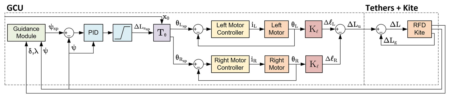
Figure 4Block diagram of the control system, including a guidance module (green), a ΔLu PID setpoint controller (blue), a transformation block (purple), two motor cascade controllers (yellow), two gain blocks (red), and the controlled plants (orange).
Two main assumptions have been made for the design of the controller. First, the radial and tangential motions of the kite on the wind sphere are considered to be decoupled, which is common practice in the literature (Rapp et al., 2019) and allows us to study the control of steering maneuvers independently of the actuation on the winch mechanism and the radial coordinate r. Second, the heading angle is assumed to be approximately equal to the actual course angle of the RFD kite during crosswind conditions. The course angle is computed like the heading angle in Eq. (8) but replacing iK by the absolute velocity vector of the kite. This assumption allows us to use the same control variable both for figure-eight maneuvers and for the hovering safe mode, in which the kite is positioned on top of the wind sphere and its absolute velocity is close to zero.
A finite-state machine approach was used to define the behavior of the guidance module. Accordingly, angle ψsp in Fig. 4 takes different values depending on the mode of operation (figure eight or hovering) and the specific segment (straight or turn) in the figure-eight trajectory. For both the straight segment and the hovering mode, the heading angle setpoint ψsp,s is defined as the angle that the kite should take to be pointed directly towards an attractor point (R± and H). Conversely, during the turning segments, ψsp,t is defined such that the kite is oriented perpendicular to the vector and points accordingly to the up-turning flight trajectory (see Fig. 3b). The initial values of these reference points and thresholds for each flight are described in Table 3. The finite-state machine transition from the straight path to the turn is based on the difference , and the transition from the turn to the straight path is initiated by monitoring .
The value of ψsp is calculated according to the great-circle navigation formulas (Fechner and Schmehl, 2016)
where j=OK for δj and λj, and R± and C± are the azimuth and elevation of the three points (see Fig. 3). Angle ψsp,t does not involve the turning radius because the proposed approach does not impose a predefined path. It rather aims to achieve a smooth circular trajectory independently of the kite's position at the end of the straight segment.
A digital PID controller is used to compute . The transfer function in the Z domain of the PID is
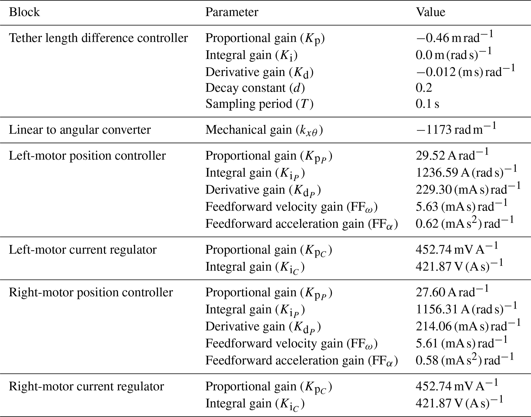
where Kp, Ki, and Kd are the proportional, integral, and derivative gains, respectively; T is the sample period of the controller; is the sampled heading angle error; and d is the decay value constant of the low-pass single-pole infinite impulse response filter used for the derivative input term. A derivative-on-measurement scheme, which computes the derivative term from the measured process variable instead of the error, is used to avoid derivative kick effects at the transition between states. T is imposed by the sample frequency of the telemetry from the flight controller, while the rest of the parameters are first tuned prior to the flight based on a simulation performed with the LAKSA software (Sánchez-Arriaga et al., 2021; delosRíos Navarrete et al., 2023). Nevertheless, all the parameters can be adjusted during the flight, and some of them were modified to improve the performance of the controller. The baseline parameters used for the flights described in Sect. 4 are given in Table 2. As shown in Fig. 4, the output of the controller is limited by a saturation function, which ensures is always within the actuator's achievable range.
Table 2Initial control parameter values. As shown in the table, the tether length difference controller is effectively used as a PD controller for the presented tests.
The transformation block Tθ converts into angular setpoints for each servomotor. By combining Eqs. (3) and (5) with a constant conversion factor kxθ to account for the mechanical relationship between the angular movement of the motors and the lineal displacement of its actuator's carriages, we yield the following transfer function:
The built-in cascade controllers of the motors used to reach the desired θsp are based on a PID position controller whose output is fed into a PI current regulator. Both controllers apply anti-windup methods. A feedforward of the angular speed and acceleration setpoints is used to compensate for velocity-proportional friction and the inertia, respectively. According to the manufacturer's documentation (Maxon, 2021), the output of the position controller, including the feedforward terms, is modeled by the transfer function
where , , and are the proportional, integral, and derivative gains; Eθ(s) is the angular position error ( or ); FFω and FFα are the feedforward gains for the angular speed and acceleration; and Rω(s) and Rα(s) are the angular speed and acceleration setpoints. The electrical current regulator transfer function, on the other hand, is described as
where and are the proportional and integral gains, and EC(s) is the electrical current error. All parameters have been tuned using the manufacturer's configuration software, and its values are given in Table 2.
As represented by the blocks Kℓ in Fig. 4, the motion of each motor varies the tether distance. To find its transfer function, we divide by kxθ and use Eq. (2) to find
As ℓj(0) is identical for both actuators, we directly find ΔLu in Eq. (4) by subtracting Eq. (2). The actual difference in length ΔL perceived by the kite is not ΔLu but rather the combination of the control input and the so-called geometric control input. As pointed out by Fagiano et al. (2014), when the output points of the control tethers on the GCU are separated by a distance dc (shown in Fig. 1 and value given in Table 1), a difference in length between the tethers is induced for the kite's positions outside the vertical plane spanned by iG and kG. The geometric control input Δg and the resulting ΔL are thus modeled as
The pitch angle of the RFD kite was controlled manually in this work, and the operator was able to tune the value of the x0 parameter, as explained in Sect. 2.2. Nonetheless, we plan to expand the control capabilities of future versions of the ground station by adding an autonomous control of the pitch. Such a capability could be particularly useful to control dynamic stall phenomena reported for RFD kites in figure-of-eight flight (Castro-Fernández et al., 2024) and to regulate the kite's pull force during reel-in operations.
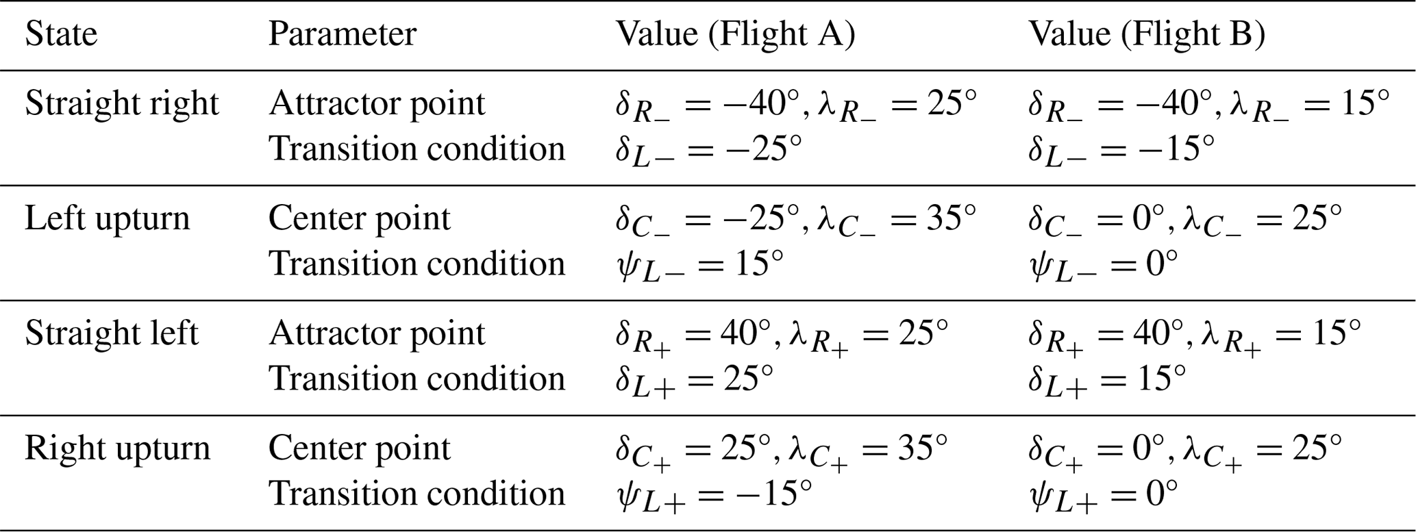
A flight test campaign was carried out on a field near Santa María de la Alameda, located on the Guadarrama mountain range of Madrid (Spain). Two flight tests have been selected to showcase the effects of the variation in the guidance parameters on the trajectory and analyze its impact on the dynamics of the RFD kite. The first flight test (denoted as Flight A) was performed with a moderate wind of 7.2 m s−1 (standard deviation of 1.5 m s−1) and lasted for 321 s from the activation of the autonomous controller. For the second flight test (Flight B), the wind was weaker, with a mean velocity of 5.4 m s−1 and a standard deviation of 1.1 m s−1, and it lasted for 53 s. In both flights the kite was piloted manually during the takeoff maneuvers, and the experiment concluded when the wind speed fell below the operational range of the kite. Tension data were recorded in both flights by the on-ground tensiometers. The data of the onboard load cells were only available for Flight B due to a sensor failure during Flight A. Table 3 shows the values of the guidance module's parameters used in both flights.
Table 3Parameters used for the guidance module state machine for each flight.
4.1 Performance of the guidance and control modules
Figure 5 shows the trajectory of the kite on the δ−λ plane for Flight A (in gray) and Flight B (in color). The magenta, brown, green, and blue colors were used to represent the leftward turns, leftward straight segments, rightward turns, and rightward straight segments in Flight B, respectively. As shown in the figure, the segments connecting the two turns are not totally straight, but, after the turn, they have two subsegments with opposite convexity. To highlight them, dark and light tonalities were used (brown and blue for the two straight segments). The analysis of the experimental results revealed that the inflection points where the concavity changes correspond to the condition , i.e., when ψ reaches extreme values. Finally, we mention that the straight segments and the turns highlighted with colors represent distinct flight conditions which are relevant in the analysis. However, as shown below, they do not necessarily match the states of the finite-state machine of the controller presented in Sect. 3.
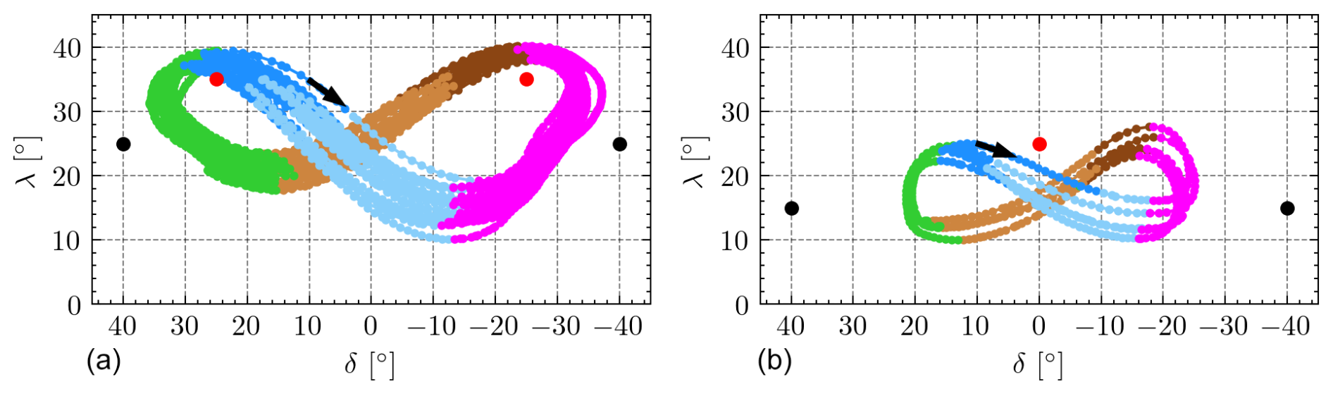
Figure 5Kite trajectory on the δ−λ plane during autonomous operation for Flight A (a) and Flight B (b). Attractor and center points are marked with black and red dots, respectively.
Flights A and B are illustrative examples of how an effective adjustment of the trajectory of the RFD kite can be achieved by tuning the parameters of the control. During Flight A, the controller was able to perform highly repeatable yet overly wide and asymmetric trajectories. The right-turning maneuver took place too far from the center of the wind window, significantly decreasing tether tension and thus resulting in impaired control capabilities. The lessons learned in Flight A were used to change the configuration of the guidance module in Flight B, which generally exhibited tighter and more symmetric trajectories and sharper turns. Narrower figure-eight paths were also achieved due to lower elevations for all reference points in the guidance module.
In Flight A, the guidance module was tuned with points C± placed at the same azimuth as the transition points L±; i.e., we took (see Table 3), and the elevation of the attractor points R± () was higher than the elevation of the kite at the straight-to-turn transition points. A consequence of this configuration was that the kite was already moving upwards when the state machine changed from the straight to the turn navigation phase. Since the heading setpoint in the turn was set perpendicular to the segment , as explained in Sect. 3, it resulted in a steering command opposed to the one that was needed to make the turn during the first instants of the turning phases, thus delaying the turning maneuver.
In Flight B, the parameters of the guidance module were changed to improve the performance. The only exception is the azimuth of the attractor points R± that were kept equal to . As shown in Table 3, the elevation angles of points C± and R± were decreased by 10° to lower the height of the figure eight and make the kite flight more perpendicular to the wind direction. As shown in Fig. 5, such a configuration successfully lowered the trajectory. Second, the azimuth angles of the straight-to-turn transition points L± were decreased from to to avoid the kite visiting the edges of the wind window during the turns. Figure 5 clearly shows the impact of such a change on the trajectory of Flight B, whose azimuth was bounded within the range . The third and last change was targeted to eliminate the unsatisfactory steering command at the beginning of the straight-to-turn transition. With this aim, the azimuth angle of points C± was set δ=0. The result was a stronger steering input in the appropriate direction.
To get a deeper understanding of the performance of the guidance module and its configuration, Fig. 6 displays the evolution of the kite heading ψ provided by the onboard computer (colored with the same code as Fig. 5) and the heading angle setpoint ψsp used by the controller (black line). Such an angle is given by Eqs. (9) and (10) for the straight and turn phases, respectively. For each flight, two representative cycles are shown. The time steps at which a transition condition is met, and the controller thus switches states according to Table 3, are marked with dashed vertical lines.
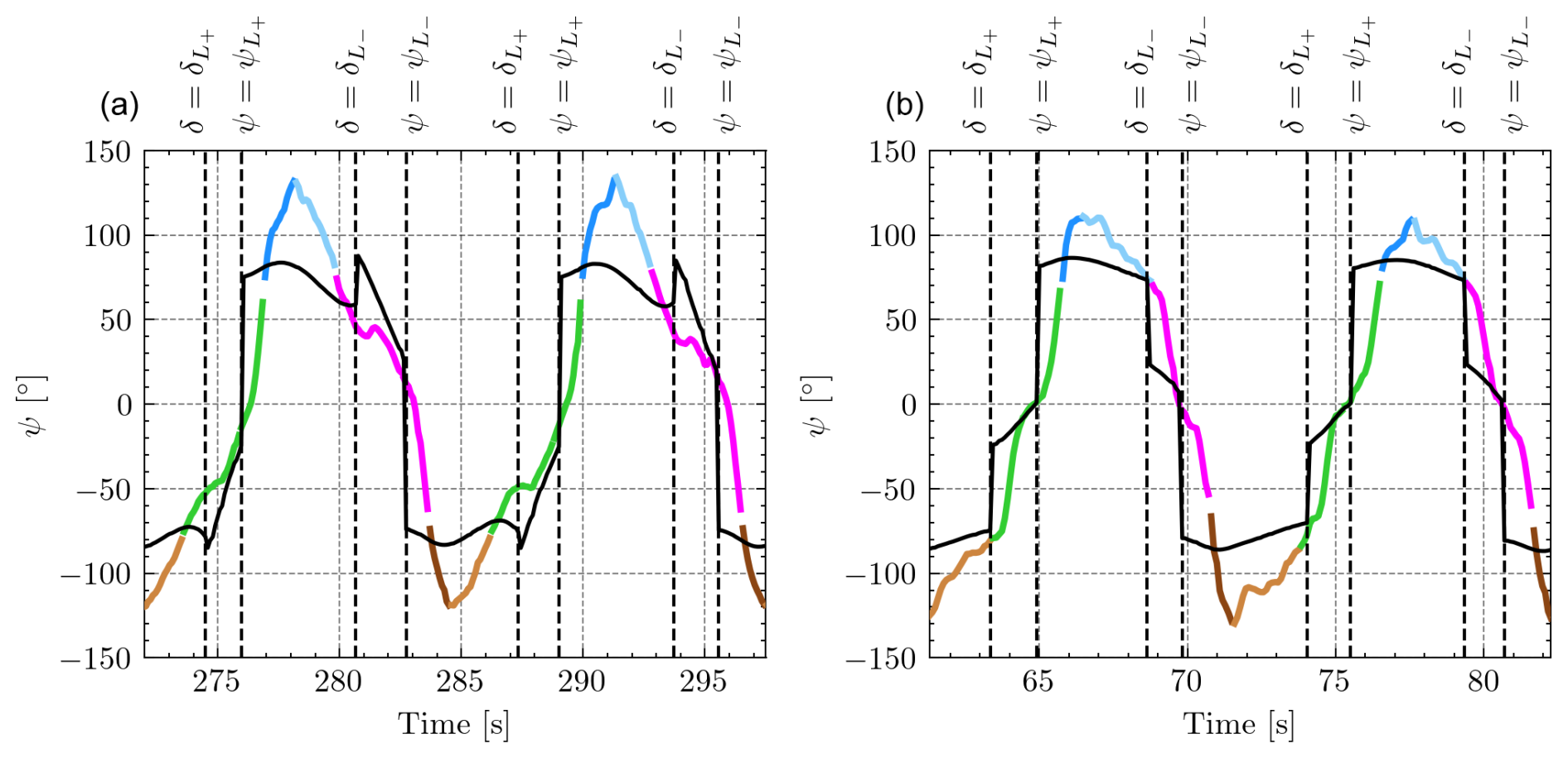
Figure 6Evolution of the heading angle ψ (colored) and the controller setpoint ψset (black) for Flight A (a) and Flight B (b) for two figure-eight cycles. Transitions between control states and their conditions are marked with dashed vertical lines. The same color code as that in Fig. 5 is used.
After analyzing the two flights, three improvements are identified in Flight B when compared to Flight A. Firstly, there is a significant overshoot during the straight segments for both flights (blue and brown segments in Fig. 6). The maximum value of the setpoint of the heading angle of the controller is around , but the kite reaches heading angles beyond ±110°. However, the overshoot is smaller for Flight B. Second, it is evident that at the beginning of the straight-to-turn transitions (from blue to pink) in Flight A, the controller provides a wrong steering command (for instance, ψsp increases at instead of decreasing). This issue was corrected by the new guidance parameters of Flight B. Notably, almost no overshoot is present during the turning segments. For Flight B, the matching between ψ and ψsp is excellent during the last part of the turnings. Since there is no overshoot in the turns and a small overshoot for Flight B in the straight segments, these results suggest implementing different control gains for the tether length controller (gains Kp, Ki, and Kd in Table 2) for each phase and for each wind speed. The third improvement is related to the timing of the transitions. For Flight B, the straight-to-turn transitions of ψ (from blue to pink and from brown to green) are very well synchronized with the transition of the state machine controller given by ψsp. The lack of synchronization, the larger value of , and the misalignment of the GCU with respect to the direction of the wind yielded wider figure-eight trajectories for Flight A.
Previous works on the control of two-line soft kites (Fagiano et al., 2014; Wood et al., 2015) and RFD kites (Castro-Fernández et al., 2023) have found the following linear dependence between ΔL and the derivative of the course angle :
where KL is the so-called steering gain, and td represents the response delay of the kite. These parameters are computed as the values that provide the minimum error of a least-squares fitting of Eq. (17) to each dataset for the points contained in the central part of the wind window (i.e., rad according to Wood et al., 2015). Figure 7 shows the results for both flights, identifying and td=0.64 s for Flight A and rad (ms)−1 and td=0.28 s for Flight B.
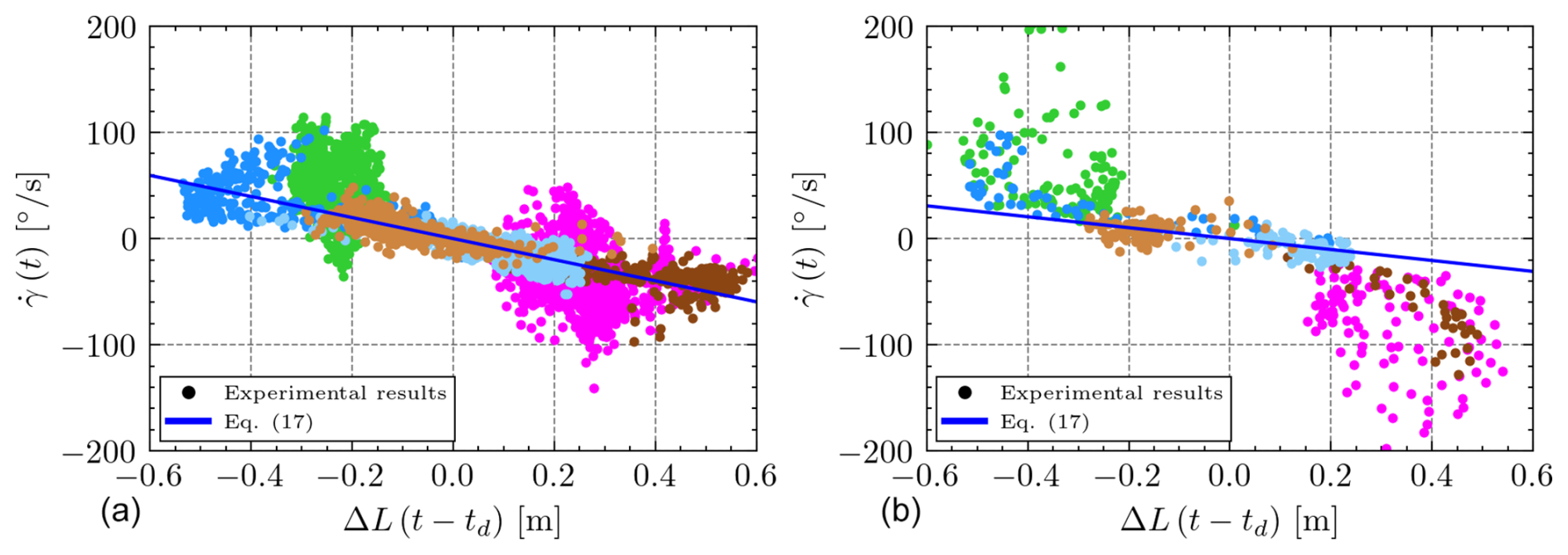
Figure 7Time derivative of the course angle () versus the delayed steering input ΔL for Flights A (a) and B (b). A least-squares fitting according to Eq. (17) for the points contained in is represented with a blue line.
The delays obtained by fitting these experimental results have the same order of magnitude as the delay reported by Castro-Fernández et al. (2023) for a similar RFD kite in a two-line configuration that was 0.2 s. In contrast, the steering gains are significantly smaller than rad (ms)−1 found in said work. However, it is worth noting that the criterion of excluding the points outside the central part of the wind window was not used in Castro-Fernández et al. (2023). The larger drag due to the third tether in our setup and the different trimming of the central tether needed for three-line operation can explain the slower dynamics. Interestingly, both datasets in Fig. 7 present a significantly smaller dispersion due to the regular nature of the closed-loop trajectories in comparison to the open-loop control of the kite in Castro-Fernández et al. (2023).
The proposed guidance and control strategy was shown to be effective for performing figure-eight trajectories in an autonomous manner. A logical step forward is to build on this result to maximize the power generated during reel-out operations (not considered in this work). The results collected in the two test campaigns suggest that an effective way to do this is by varying the parameters of the guidance module (see Table 3) while monitoring the output power. During long test flights, the parameters could be varied one by one, and the acquired data can be combined with machine learning techniques to find optimum configurations as a function of the wind velocity. Another option is to first find theoretical optimal trajectories by using simulations and then try to follow them with the testbed by changing the parameters of the guidance module. The latter strategy has the advantage of involving part of the work with a computer instead of hardware, but it has the drawback of needing reliable aerodynamic and dynamic models for the kite. The same strategy, i.e., varying the parameters of the guidance module during test flights, can also be used to investigate the minimum radius of the curvature of the kite during turns.
4.2 Kite and tether dynamics
To get insight into the dynamics of semi-rigid and hybrid kites, such as the RFD kite used for this study, the relationships between our control variable ψ and different state variables of the kite were analyzed. A strong correlation between ψ and the roll angle (ϕ) was found, as shown in Fig. 8. In order to model this relationship, we propose the function
where A, B, and C are empirical coefficients related to the amplitude of the roll range and its rates of change during the turns and the straight segments, respectively. A fitting to the experimental results provides A=1.76, B=1.82, and C=0.707 for Flight A and A=1.53, B=3.85, and C=0.644 for Flight B. This novel relationship is useful for the future design of three-line RFD kite controllers. An interesting research topic, which is beyond the scope of this work, is its application to two-line RFD kites in order to determine whether the third line has a significant effect on this correlation.
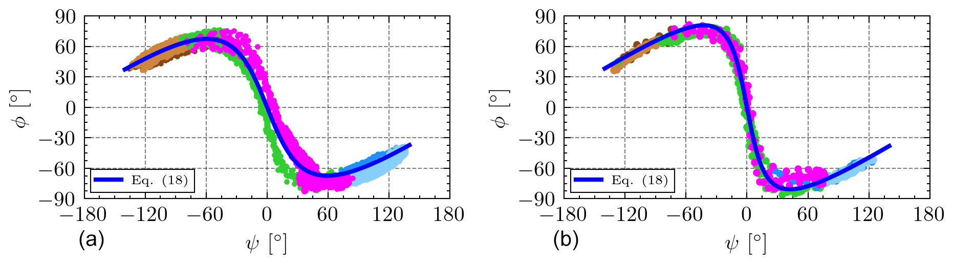
Figure 8Experimental results (dots) and fitting (blue line) of the heading angle (ψ) versus the roll angle (ϕ) for Flight A (a) and Flight B (b).
As shown in Fig. 8, and as noted in the first paragraph of Sect. 4.1, the extreme values (maximum and minimum) of the heading angle ψ occur within the straight segments and where the dark and light subsegments meet. During the turns (green and magenta), the steering input induces a change of sign in the roll angle. Flights A and B exhibit some important differences. First, the ϕ−ψ curve in Flight A has certain hysteresis within the turns of the path (pink and green colors), probably because the turns occur at the extreme of the wind window and the contribution of ΔLg to the induced roll is significant. On the contrary, the ϕ−ψ curve of Flight B presents a univocal relationship. The slope in the turn, which corresponds to the straight segment in Fig. 8, is higher in Flight B. Since the tether control mainly commands a change in the roll angle for our three-line RFD kite, we conclude that in Flight B the response of the kite to the command in the turns was weaker. This interesting experimental result can be explained by the lower wind velocity in Flight B.
A singular characteristic of the experimental setup of this work is the measurement of the on-ground and onboard tether tensions. Figure 9 shows them during three figure-eight cycles of Flight B, with the colored points being the measurements of the on-ground tensiometers and the dashed lines corresponding to the onboard load cells. Panels (a)–(d) correspond to the total tension and the central, left, and right tethers, respectively. The evolution of the tension on the central tether closely follows the behavior of the total tether tension, with about one half of its magnitude. This result shows that the control action produces a redistribution of the tensions in the steering (left and right) tethers. The total tension rises during the downwards straight sections and decreases sharply during the upwards turns, in agreement with the expected behavior of this kind of trajectory (Erhard and Strauch, 2015). The tension on the right (left) control tether increases during the right (left) turns. The maxima in the tension of the left tether correspond to the minima of the right tether and vice versa.
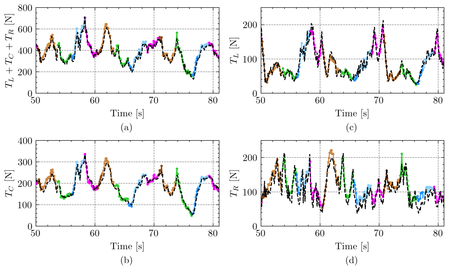
Figure 9Evolution of tether tensions measured by the on-ground tensiometers (colored points, with the same color code as in Fig. 5) and the onboard load cells (dashed black lines) for three figure-eight cycles of Flight B. Time t=0 is the takeoff.
No significant differences are observed in magnitude between the air and ground load cells. However, a delay ranging between 0.1 and 0.2 s was observed. Such a delay, which only affects the tethers, is smaller than the steering kite gain delay found in Sect. 4.1, which involves the tether and the kite. To understand this tether delay, we estimate the speed of longitudinal and transversal waves traveling through a tether as
where E is Young's modulus of the tether material, ρ is its volumetric density, T is the mean tension on the tether, and μ is its linear density (French, 1971). These equations yield a longitudinal and transversal wave speed of 13 211 and 299 m s−1 for the central tether during Flight B. As the length of the tethers during the flight was approximately 95 m, the characteristic times for a perturbation measured by the onboard load cells to reach the on-ground load cells (or vice versa) were about 7 ms and 0.3 s. As expected, the delay observed in the experimental results is due to the finite velocity of the transversal waves in the tether. Interestingly, the experimental setup is able to capture this important effect, and it could be used in future works to study the delay as a function of the tether length and tether sagging for AWE systems.
The improvements implemented in the GCU and the RFD kite of the small-scale testbed of the UC3M extended the capabilities of the infrastructure considerably and opened new possibilities for its application to the research of AWE systems. These improvements include a modification of the mechanical control system by adding a third tether and providing pitch control, the use of running-line tensiometers to measure the three tether tensions while allowing for tether reel-in and reel-out, the addition of onboard load cells attached to the bridle lines to measure the tether tensions on the kite, and the use of a real-time controller for the autonomous flight of the kite. The proposed architecture of the mechanical control system, the electronic system architecture, and the guidance and control modules developed in this work yielded a system capable of performing figure-eight cycles autonomously and consistently while providing valuable scientific data for AWE systems.
A flight campaign with two different flights revealed that the PID controller, which is based on a hybrid guidance strategy that uses attractor points for the straight segments of the cycle and a continuous formulation for the turns, validated the autonomous operation of the testbed for three-line RFD kites. More importantly, it was shown that the shape of the figure-eight cycles, including its lateral amplitude, elevation, and radius of the turns, can be chosen by tuning the parameters of the controller. Since the latter is the azimuth and elevation angles of certain characteristic points of the guidance module, as well as the transition values of the heading angle to change from straight to turn phases, the setting of the parameters of the controller is intuitive. Simple plots of the kite's heading angle and the heading angle setpoint of the controller can be used to tune its parameters. The analysis of the results showed that the performance could be improved even more by applying a gain-scheduling control scheme for the straight and turn phases and the wind conditions.
The RFD kite flying autonomously and following highly repeatable figure-eight trajectories allowed us to investigate interesting matters related to the dynamics of the tethers and the kite. A linear dependence between the control action and the derivative of the course angle was identified and characterized. The analysis reveals a significantly slower dynamic than reported in a previous work for the same RFD kite but in a two-line configuration. The aerodynamic drag on the third line and a different kite trimming can explain this. On the other hand, a strong correlation between the heading and roll angles of the RFD kite was found and modeled by a simple analytical formula with coefficients found from the experimental data. This correlation may be useful to characterize the dynamic behavior of a kite for a given trajectory and control system. Its application to two-line RFD kites is another open problem to be studied in the future. Finally, the analysis of the tether tension evolution during the figure-eight trajectories revealed the distribution among the three lines as a function of the actuation. The real-time measurement of the tether tensions by the onboard load cells and on-ground tensiometers demonstrated that the loads are very similar for our short tether configuration. A variable time delay between 0.1 and 0.2 s between both measurements associated with the propagation velocity of transversal waves along the tether was identified. Future works can be conducted to correlate this phenomenon to relevant variables in AWE systems, such as tether sagging and length.
Since the test campaigns validated the small-scale testbed and the guidance and control solutions presented in this work, the preparation of a upscaled version of the testbed was triggered. A mechanical-to-electrical power conversion system was added, and several elements, such as the actuators and the drum, were scaled up to operate larger kites. The design, manufacturing, and integration phases have been completed, and the fist test campaigns have been implemented.
Code developed and data used for this study can be made available by the authors upon reasonable request.
FDN, ICF, and GSA conceptualized the architecture of the mechanical control system. FDN designed and built the mechanical control system and developed the software. FDN and JGG planned and carried out the experiments. All authors significantly contributed to the analysis and discussion of the results. FDN wrote the paper in consultation with GSA, JGG, and ICF. GSA supervised the project. All authors read and agreed to the published version of the paper.
The contact author has declared that none of the authors has any competing interests.
Publisher's note: Copernicus Publications remains neutral with regard to jurisdictional claims made in the text, published maps, institutional affiliations, or any other geographical representation in this paper. While Copernicus Publications makes every effort to include appropriate place names, the final responsibility lies with the authors.
This work is part of project PID2022-141520OB-I00 funded by MICIU/AEI/10.13039/501100011033. Francisco DeLosRíos-Navarrete was supported by grant IND2022/AMB-23521 funded by Comunidad de Madrid.
This research has been supported by Comunidad de Madrid (grant no. IND2022/AMB-23521) and MICIU/AEI/10.13039/501100011033 (grant no. PID2022-141520OB-I00).
This paper was edited by Roland Schmehl and reviewed by three anonymous referees.
Ahrens, U., Diehl, M., and Schmehl, R. (Eds.): Airborne Wind Energy, Green Energy and Technology, Springer, Berlin, Heidelberg, https://doi.org/10.1007/978-3-642-39965-7, 2013. a
Alexander, K. and Stevenson, J.: A test rig for kite performance measurement, P. I. Mech. Eng. B-J. Eng., 215, 595–598, https://doi.org/10.1243/0954405011518412, 2001. a
Azaki, Z., Dumon, J., Meslem, N., and Hably, A.: Sliding Mode Control of Tethered Drone: Take-off and Landing under Turbulent Wind conditions, in: 2023 International Conference on Unmanned Aircraft Systems (ICUAS), Warsaw, Poland, 6–9 June 2023, 769–774, https://doi.org/10.1109/ICUAS57906.2023.10156617, 2023. a
Bartsch, T., Knipper, P., Grazianski, S., Noga, R., and Paulig, X.: SkySails PN-14 Power Curve Measurement, Airborne Wind Energy Conference 2024, Madrid, Spain, 24–26 April 2024, https://repository.tudelft.nl/islandora/object/uuid%3A24968992-e316-4fa5-be53-4b601f92bf09 (last access: 17 May 2024), 2024. a
Bechtle, P., Schelbergen, M., Schmehl, R., Zillmann, U., and Watson, S.: Airborne wind energy resource analysis, Renew. Energ., 141, 1103–1116, https://doi.org/10.1016/j.renene.2019.03.118, 2019. a
Bormann, A., Ranneberg, M., Kövesdi, P., Gebhardt, C., and Skutnik, S.: Development of a Three-Line Ground-Actuated Airborne Wind Energy Converter, in: Airborne Wind Energy, edited by: Ahrens, U., Diehl, M., and Schmehl, R., Springer, Berlin, Heidelberg, 427–436, https://doi.org/10.1007/978-3-642-39965-7_24, 2013. a
Borobia-Moreno, R., Ramiro-Rebollo, D., Schmehl, R., and Sánchez-Arriaga, G.: Identification of kite aerodynamic characteristics using the estimation before modeling technique, Wind Energy, 24, 596–608, https://doi.org/10.1002/we.2591, 2021. a, b
Candade, A. A., Ranneberg, M., and Schmehl, R.: Structural analysis and optimization of a tethered swept wing for airborne wind energy generation, Wind Energy, 23, 1006–1025, https://doi.org/10.1002/we.2469, 2020. a
Castro-Fernández, I., DeLosRíos-Navarrete, F., Borobia-Moreno, R., Fernández-Jiménez, M., García-Cousillas, H., Zas-Bustingorri, M., Ghobaissi, A. T., López-Vega, F., Best, K., Cavallaro, R., and Sánchez-Arriaga, G.: Automatic testbed with a visual motion tracking system for airborne wind energy applications, Wind Energy, 26, 388–401, https://doi.org/10.1002/we.2805, 2023. a, b, c, d, e, f
Castro-Fernández, I., Cavallaro, R., Schmehl, R., and Sánchez-Arriaga, G.: Unsteady Aerodynamics of Delta Kites for Airborne Wind Energy Under Dynamic Stall Conditions, Wind Energy, 27, 936–952, https://doi.org/10.1002/we.2932, 2024. a
Cherubini, A., Papini, A., Vertechy, R., and Fontana, M.: Airborne Wind Energy Systems: A review of the technologies, Renew. Sust. Energ. Rev., 51, 1461–1476, https://doi.org/10.1016/j.rser.2015.07.053, 2015. a
Cobb, M., Deodhar, N., and Vermillion, C.: Lab-Scale Experimental Characterization and Dynamic Scaling Assessment for Closed-Loop Crosswind Flight of Airborne Wind Energy Systems, J. Dyn. Syst.-T. ASME, 140, 071005, https://doi.org/10.1115/1.4038650, 2018. a
Coca-Tagarro, I.: Site Identification Analysis for AWE Devices. A case study in Germany, Tech. rep., Zenodo, https://doi.org/10.5281/zenodo.10462306, 2023. a
delosRíos Navarrete, F., Castro-Fernández, I., Cavallaro, R., and Sánchez-Arriaga, G.: Experimental validation of an airborne wind energy simulator based on a semi-empirical aerodynamic model, Zenodo, https://doi.org/10.5281/zenodo.8086316, 2023. a
Diwale, S., Faulwasser, T., and Jones, C. N.: Model Predictive Path-Following Control for Airborne Wind Energy Systems, IFAC PapersOnLine, 50, 13270–13275, https://doi.org/10.1016/j.ifacol.2017.08.1964, 2017. a
Erhard, M. and Strauch, H.: Flight control of tethered kites in autonomous pumping cycles for airborne wind energy, Control Eng. Pract., 40, 13–26, https://doi.org/10.1016/j.conengprac.2015.03.001, 2015. a
Fagiano, L., Zgraggen, A. U., Morari, M., and Khammash, M.: Automatic Crosswind Flight of Tethered Wings for Airborne Wind Energy: Modeling, Control Design, and Experimental Results, IEEE T. Contr. Syst. T., 22, 1433–1447, https://doi.org/10.1109/TCST.2013.2279592, 2014. a, b, c
Fagiano, L., Quack, M., Bauer, F., Carnel, L., and Oland, E.: Autonomous Airborne Wind Energy Systems: Accomplishments and Challenges, Annual Review of Control, Robotics, and Autonomous Systems, 5, 603–631, https://doi.org/10.1146/annurev-control-042820-124658, 2022. a
Fechner, U. and Schmehl, R.: Flight path control of kite power systems in a turbulent wind environment, in: 2016 American Control Conference (ACC), Boston, MA, USA, 6–8 July 2016, 4083–4088, https://doi.org/10.1109/ACC.2016.7525563, 2016. a, b
French, A. P.: Vibrations and waves, M.I.T. Introductory Physics Series, Norton, New York, ISBN 978-0-393-09924-9, 1971. a
Hummel, J., Göhlich, D., and Schmehl, R.: Automatic measurement and characterization of the dynamic properties of tethered membrane wings, Wind Energ. Sci., 4, 41–55, https://doi.org/10.5194/wes-4-41-2019, 2019. a
Kitekraft: Kitekraft Blog: First grid-connected flight with power production, https://www.kitekraft.de/blog/first-grid-connected-flight-with-power-production (last access: 10 May 2024), 2023. a
Kitemill: Kitemill Breaking Records for Automatic Operation, https://www.kitemill.com/news/kitemill-breaking-records-for-automatic-operation (last access: 9 May 2024), 2023. a
Maxon: Controller Architecture, in: IDX Application Notes, Beckhoff Automation GmbH, https://www.maxongroup.com/medias/sys_master/root/8884071170078/IDX-Application-Notes-Collection-En.pdf (last access: 7 July 2024), 2021. a
Oehler, J. and Schmehl, R.: Aerodynamic characterization of a soft kite by in situ flow measurement, Wind Energ. Sci., 4, 1–21, https://doi.org/10.5194/wes-4-1-2019, 2019. a
Rapp, S., Schmehl, R., Oland, E., and Haas, T.: Cascaded Pumping Cycle Control for Rigid Wing Airborne Wind Energy Systems, J. Guid. Control Dynam., 42, 2456–2473, https://doi.org/10.2514/1.G004246, 2019. a
Sánchez-Arriaga, G., Serrano-Iglesias, J. A., Leuthold, R., and Diehl, M.: Modeling and Natural Mode Analysis of Tethered Multi-Aircraft Systems, J. Guid. Control Dynam., 44, 1199–1210, https://doi.org/10.2514/1.G005075, 2021. a
Schmidt, H., de Vries, G., Renes, R. J., and Schmehl, R.: The Social Acceptance of Airborne Wind Energy: A Literature Review, Energies, 15, 1384, https://doi.org/10.3390/en15041384, 2022. a
Wood, T., Hesse, H., and Smith, R.: Predictive control of autonomous kites in tow test experiments, IEEE Control Systems Letters, 1, 110–115, https://doi.org/10.1109/LCSYS.2017.2708984, 2017. a
Wood, T. A., Hesse, H., Zgraggen, A. U., and Smith, R. S.: Model-based identification and control of the velocity vector orientation for autonomous kites, in: 2015 American Control Conference (ACC), Chicago, IL, USA, 1–3 July 2015, 2377–2382, https://doi.org/10.1109/ACC.2015.7171088, 2015. a, b, c