the Creative Commons Attribution 4.0 License.
the Creative Commons Attribution 4.0 License.
 | 22 Dec 2025
Analyzing the impact of aeroelastic model fidelity on control co-design optimization of floating offshore wind turbines
Robert Behrens de Luna
Francesco Papi
David Marten
Christian Oliver Paschereit
This work investigates the influence of aeroelastic modeling fidelity on design optimization of floating offshore wind turbines. To this end, the QBlade simulation environment was coupled to the Wind Energy with Integrated Servo-control wind turbine design and optimization framework. QBlade offers aerodynamic and structural models with varying levels of aeroelastic fidelity within a computationally efficient implementation. This enables time-domain optimization studies with levels of aeroelastic fidelity that are currently often deemed unfeasible for such purposes due to the computational expense involved. Five fidelity combinations are considered, ranging from blade element momentum aerodynamics with torsion-constrained Euler–Bernoulli beams to lifting-line free vortex wake aerodynamics with fully populated Timoshenko beams. To assess how aerodynamic and structural modeling fidelity influences optimization outcomes, the parameters of the floating wind turbine controller are co-designed together with the floating substructure, a system typically considered less sensitive to aeroelastic fidelity. The results show that final design outcomes are affected by the chosen fidelity level. In this case study, higher-fidelity models modified and broadened the feasible design space and thereby led to improved design outcomes, albeit at the expense of higher computational cost.
- Article
(7075 KB) - Full-text XML
- BibTeX
- EndNote


Floating offshore wind turbines (FOWTs) enable renewable energy generation in deeper waters where the installation of fixed-bottom systems is not feasible. Even though these systems have received significant attention in recent years, their complexity and cost continue to pose significant barriers to their widespread deployment. A comparison of capital expenditures (CapExs) between FOWTs and their fixed-bottom counterparts shows that the floating substructure is a major cost driver (Ghigo et al., 2020). In order to address this economic challenge and to enable broad deployment of floating wind, optimization across all system components is required. Traditional sequential optimization strategies, in which each subsystem is optimized in isolation while others remain fixed, build in conservative assumptions at each design step and can therefore lead to sub-optimal overall system designs for strongly coupled systems like FOWTs (Garcia-Sanz, 2019). As a consequence, the multidisciplinary design analysis and optimization (MDAO) approach has gained attention within the research community. MDAO uses coupled analysis models to account for coupled physical phenomena across subsystems. Thereby, MDAO enables the simultaneous variation of design variables from different subsystems and potentially leads to more cost-effective design solutions (Martins and Ning, 2022). Ojo et al. (2022) summarize the current state of MDAO in the context of FOWTs and outline the key frameworks, trends and remaining challenges in this field. One category within MDAO is control co-design (CCD), which describes the simultaneous optimization of both the physical system and its controller. CCD has shown potential to improve performance, reduce structural loads and lower total system cost by exploiting dynamic interactions between the physical system and its controller for tightly coupled systems (Garcia-Sanz, 2019). The benefits of CCD depend on the accuracy of the underlying models. At the same time, the interaction between aerodynamics, structural dynamics and the controller of wind turbines is becoming increasingly complex due to larger and more flexible rotors. Therefore, increasing the aeroelastic fidelity in MDAO tools to accurately capture these interactions could be essential (Veers et al., 2022).
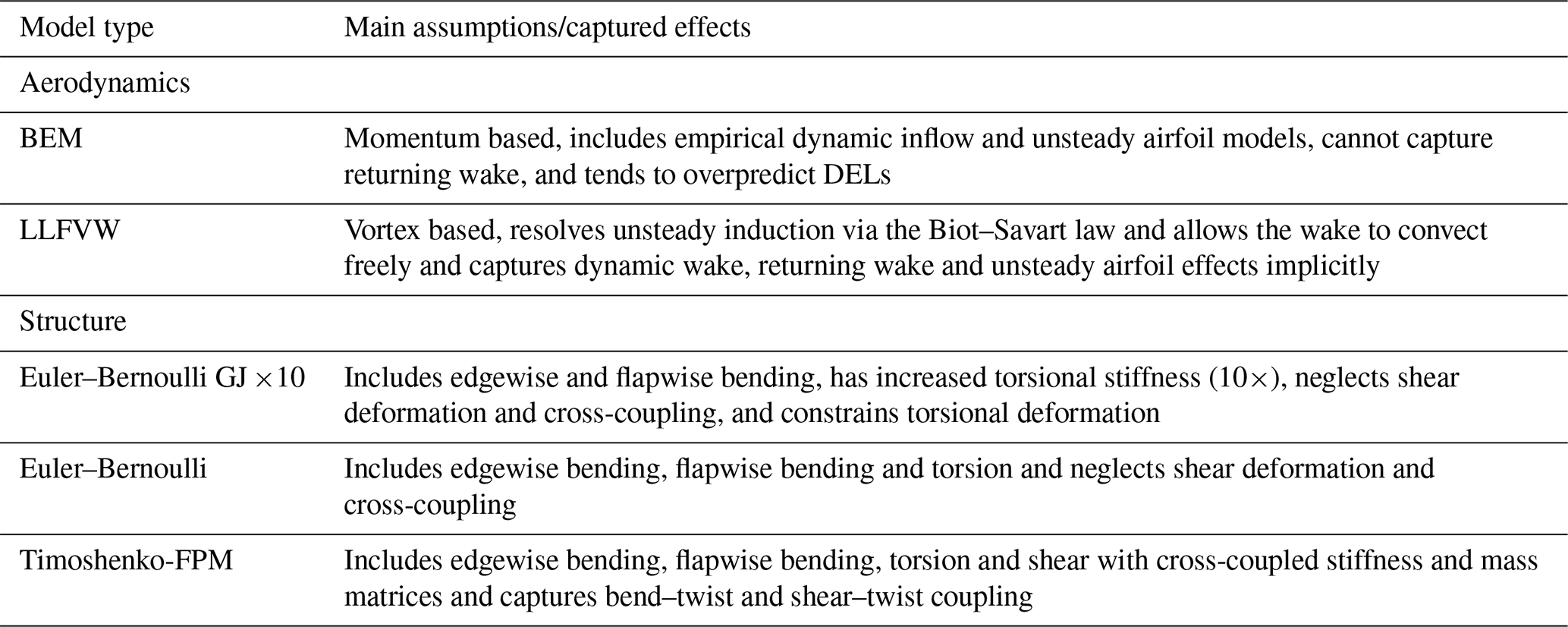
Current industry-standard simulation tools rely on low- to mid-fidelity models, like the blade element momentum (BEM) method for aerodynamics and simplified beam theories for structural dynamics. The latter do not account for couplings between degrees of freedom of a beam element. The key enabler of the BEM method is its computational efficiency. However, the method requires several empirical corrections and can introduce significant uncertainty (Perez-Becker et al., 2020; Boorsma et al., 2020; Hauptmann et al., 2014). This is particularly true when the operating conditions are unsteady, e.g., during blade–wake interactions or dynamic inflow conditions (Ramos-García et al., 2022; Schulz et al., 2025). Recent studies indicate that using lifting-line free vortex wake (LLFVW) methods (Behrens de Luna et al., 2024; Papi et al., 2024b; Schulz et al., 2025) or advanced beam models that resolve the coupled dynamics between degrees of freedom (Zhao et al., 2025; Stäblein, 2016) may offer a pathway to more precise aeroelastic modeling.
Recent CCD studies for FOWTs used the Wind Energy with Integrated Servo-control (WEIS) framework and showed that simultaneous optimization of physical and control parameters can reduce structural mass, cost or loads. Zalkind et al. (2022) optimized controller parameters for the IEA 15 MW turbine on varying floating platform types. Zalkind and Bortolotti (2024) found a 2 % lighter platform mass configuration for the IEA 22 MW VolturnUS-S when using simultaneous instead of sequential CCD. Abbas et al. (2024) found a levelized cost of energy (LCOE) reduction of up to 4 % when co-optimizing the platform and controller. The above-mentioned studies used OpenFAST as the simulation tool. The tool was set up to use the BEM method for aerodynamics and the ElastoDyn (NREL, 2025b) module for structural dynamics, which omits the blade torsional degree of freedom. Outside of WEIS, frameworks such as Yu et al. (2024) and Bayat et al. (2025) have applied CCD to FOWTs but typically use reduced-order aeroelastic models to limit computational cost. The influence of increased aeroelastic fidelity on design outcomes, particularly in the context of control co-design, remains largely unexplored.
To address this gap, this work builds upon the WEIS framework. Recent developments under the FLOATFARM (FLOATFARM, 2025) project have enabled the integration of the QBlade simulation code into WEIS. QBlade offers BEM and lifting-line free vortex wake aerodynamic models, as well as a structural solver that allows Euler–Bernoulli, Timoshenko or Timoshenko fully populated matrix (FPM) beams to be selected, enabling fidelity variation within a unified workflow. The use of QBlade has been instrumental in keeping overall computational cost reasonable. The Timoshenko-FPM approach adds only minimal computational overhead compared to simpler approaches. Moreover, while the lifting-line solver adds significant computational cost, QBlade allows for its impact to be significantly reduced by exploiting graphics processing units (GPUs). The contribution of this work to the literature is two-fold: first, the development and introduction of an optimization framework, called QBtoWEIS, which builds on the capabilities of WEIS and enables a direct comparison of optimization outcomes obtained with different aeroelastic fidelity levels available in QBlade and, second, the application and demonstration of this new tool to a modern and highly flexible reference turbine, such as the IEA 22 MW. This turbine was explicitly designed with passive load mitigation via bend–twist coupling in mind (Zahle et al., 2024a) and thus allows for a realistic assessment of aeroelastic fidelity effects on a complex system. In doing so, new insights into the trade-offs between aeroelastic model fidelity, computational cost and final optimum are provided. This work specifically addresses a gap that was recently outlined by a pool of experts in the wind energy community (Veers et al., 2022), which is the integration of advanced aeroelastic simulation tools into the design process and usage of increased fidelity models within optimization workflows.
In Sect. 2, we provide an overview of QBtoWEIS along with some theoretical background about the methods relevant for the optimizations carried out in this work. Section 3 is focused on the definition of the optimization problem and modeling considerations. In Sect. 4, the results are present and discussed.
2.1 Control co-design
Control co-design has recently drawn increased attention in the context of floating offshore wind turbines. The reason for this is that FOWTs are highly coupled, nonlinear systems that consist of several subsystems, with the main ones being the wind turbine itself, the floating substructure, the mooring system and the servo-control system. These subsystems comprise multiple subsystems in their own right. The wind turbine, for instance, is composed of the rotor nacelle assembly (RNA), the generator and the tower. Modifying only one of these components can have a significant impact on the overall system behavior of the floating offshore wind turbine. If, for instance, the tower is to be optimized with the aim of reducing its weight (and thereby cost), it is crucial to consider the rotor rotational speed (1P) and blade-passing (3P) frequencies to ensure that natural frequencies do not coincide with excitation frequencies during operation. Yet, not all interactions are as obvious as the tower–blade interaction, and in order to avoid negative interactions between subsystems, it is important to take a multidisciplinary design approach. CCD is a category of MDAO, where the design of a controller takes place at the same time at which the physical system is designed or optimized. It represents a contrast to the sequential design approach, in which the controller is usually the final part of the design iteration. As pointed out by Garcia-Sanz (2019), the CCD approach leads to designs with improved system dynamics and controllability, ultimately resulting in lower costs and increased reliability.
In a typical CCD problem, the design variables may include the internal layer thicknesses of the blade layup or platform sizing parameters along with the controller bandwidths or damping ratios. For example, Abbas et al. (2024) demonstrate a tower–controller CCD optimization in which tower wall thickness and diameter were co-optimized with the pitch controller bandwidth and damping ratio, floating feedback gain, low-pass-filter frequency, and the peak shaving percentage.
2.2 QBlade in the WEIS framework
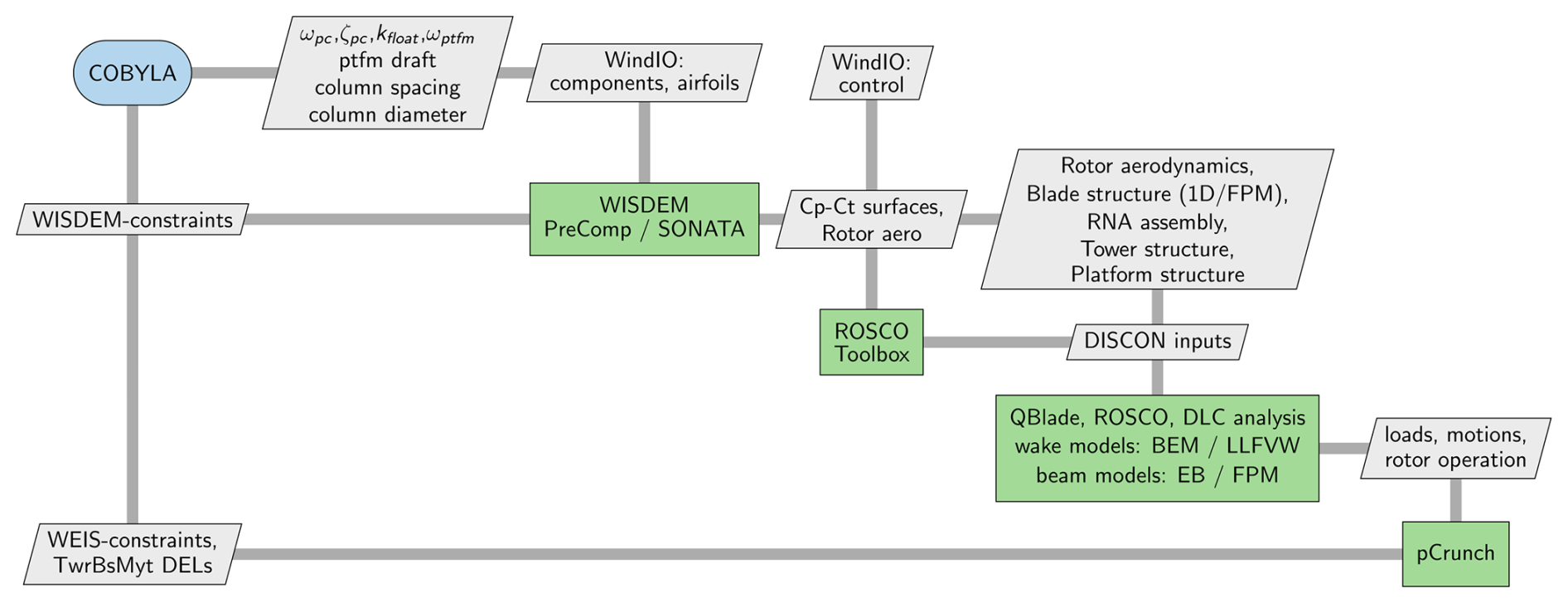
WEIS (NREL, 2025f), short for Wind Energy with Integrated Servo-control, is a design framework developed by the National Renewable Energy Laboratory (NREL) for co-design of floating offshore wind turbines and their control systems. The framework integrates existing tools such as WISDEM (NREL, 2025g), OpenFAST (NREL, 2025c), ROSCO (NREL, 2025d) and pyHAMS (NREL, 2025i) into a unified workflow. Any wind turbine definition in the windIO (Bortolotti et al., 2022) format can be used as a starting point for an analysis or optimization. The framework is built on the OpenMDAO Python library (Gray et al., 2019), and most of the tools are integrated as explicit components. This implementation enables efficient connection of corresponding inputs and outputs between tools in a Python class that is often referred to as the glue code. The widely distributed QBlade simulation tool (QBlade, 2025) was expanded by a hydrodynamic module, which makes the tool suitable for modeling floating offshore wind turbines. It has been validated against experimental data (Behrens de Luna et al., 2024) and benchmarked against numerous other tools in varying conditions (Behrens de Luna et al., 2022, 2024; Papi et al., 2024b; Collier et al., 2024; Bergua et al., 2023). Recent advancements in the FLOATFARM project (FLOATFARM, 2025) have led to the integration of the multi-fidelity simulation code QBlade into the WEIS framework. This coupling is henceforth referred to as QBtoWEIS (Behrens de Luna, 2025). Similar to OpenFAST, QBlade runs nonlinear time-domain simulations. The integration enables increased-fidelity methods within design and optimization studies through QBlade's efficient implementation of the lifting-line method and Timoshenko-FPM beam elements. A more detailed description of the modeling approaches implemented in QBlade and their potential impact on design is provided in the following sections. As shown in Fig. 1, an OpenMDAO component was created and embedded in the glue code of WEIS to efficiently manage the exchange of inputs and outputs between QBlade and other WEIS and WISDEM components, such as structural properties of the tower, floating platform natural frequencies and pitch control tuning parameters. An overview of the capabilities of WEIS and a discussion of available optimizers and related case studies can be found in Zalkind et al. (2022), Zalkind and Bortolotti (2024), and WEIS Documentation (2025).
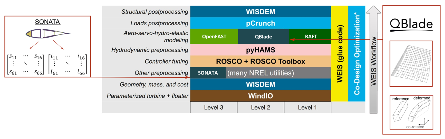
Figure 1Tool stack of the QBtoWEIS framework. The newly integrated tools QBlade and SONATA (dark blue boxes) provide an alternative option for aero-servo-hydro-elastic modeling. QBtoWEIS extends the WEIS workflow (Zalkind et al., 2022). Figure adapted from Zalkind and Bortolotti (2024). Blade vortex lattice and beam sketch adapted from Marten (2020).
In order to obtain the equivalent beam parameters required for the Timoshenko-FPM beam model (i.e., the off-diagonal stiffness and inertia values), the Structural Optimization and Aeroelastic Analysis (SONATA) code was integrated into WEIS as an additional OpenMDAO component (Fig. 1). This step is necessary because PreComp, the current cross-sectional analysis tool available in WEIS, does not provide off-diagonal stiffness or inertia terms, nor shear stiffness (GA). SONATA is a cross-sectional analysis tool capable of deriving equivalent structural properties in the form of full 6×6 stiffness and inertia matrices for composite structures (Feil et al., 2020). SONATA was originally developed at the Institute for Rotorcraft and Vertical Flight, formerly the Helicopter Technology Institute of the Technical University of Munich (TUM, 2025), and was later adapted for wind turbine blade applications by NREL (NREL, 2025e). The tool builds on the open-source Python-based code for anisotropic beam analysis, ANBA v4.0 (Morandini et al., 2010). The integration of SONATA into QBtoWEIS enables co-design of problems that include blade-related design variables, such as chord, twist, fiber angle and spar cap thickness, with the structural blade modeled with Timoshenko-FPM beams. Ongoing work by the authors uses this capability to systematically evaluate the impact of different cross-sectional analysis tools on the optimized blade design of a low-specific-power 15 MW rotor.
2.3 Aerodynamic wake methods in QBlade
QBlade encompasses an unsteady blade element momentum and a lifting-line free vortex wake method. According to Perez-Becker et al. (2020), who systematically compared both wake methods under realistic conditions, the fatigue loads at several load sensors representative of a wind turbine's overall load response (e.g., blade root and tower-base bending moments) are overpredicted by the BEM method. However, the BEM method used for the comparison did not include dynamic inflow correction, and a qualitative comparison with a BEM method that included this correction appeared to reduce the discrepancy between the models. In Papi et al. (2024b), the authors confirmed similar findings when the comparison was performed in floating offshore conditions. Based on these findings, a reasonable assumption would be that including a lifting-line free vortex model in the design phase could allow for more efficient design solutions. Boorsma et al. (2016) compared momentum-based and vortex-based methods, validating them with the New MEXICO (Boorsma and Schepers, 2014) campaign. They observed better agreement between the higher-fidelity method and the experiment in dynamic conditions, leading them to a similar conclusion concerning improved designs and reduced uncertainty if vortex methods are used. Schulz et al. (2025) systematically analyzed load amplitudes of the rotor thrust force in fore–aft oscillation load cases and considered frequency ranges that are typical for large FOWTS. They found that the dynamic wake effect, returning wake and unsteady airfoil effects result in discrepancies between the BEM and LLFVW methods in unsteady scenarios. All of the aforementioned effects are captured by the LLFVW method, while the BEM method requires empirical corrections to capture dynamic wake and unsteady airfoil effects. However, the BEM method is incapable of capturing the returning wake event. Among these three unsteady effects, the dynamic wake effect is the most prevalent, even in scenarios involving very slow fore–aft oscillation of the rotor. Even though the choice of aerodynamic method has implications for disciplines that do not solely focus on loads (e.g., wake propagation, wake breakdown, turbine-to-turbine interaction), the focus of this work lies solely on loads. In this context, the wake methods largely differ in how they calculate the wake-induced velocities.
2.3.1 Blade element momentum theory
The blade element momentum theory has been the industry standard to simulate loads on a wind turbine for several decades. Its fundamental algorithm is detailed in widely used textbooks (Hansen, 2008; Burton et al., 2001). Essentially, as the name implies, the theory combines momentum and blade element theories to find two expressions of the aerodynamic thrust and two expressions of the aerodynamic torque, which are iterated to solve for the axial induction factor a and the tangential induction factor a′. By finding consistent values of a and a′ from both theories, an equilibrium state is established. Over the years, many engineering models have been applied to the BEM algorithm to address certain shortcomings that are related to assumptions that are made by the BEM method (Branlard et al., 2022; Madsen et al., 2020; Snel and Schepers, 1995; Buhl, 2005). The implementation in QBlade closely follows the unsteady polar BEM method as described by Madsen et al. (2020).
2.3.2 Lifting-line free vortex wake
The LLFVW method implemented in QBlade builds on the fundamental work of Prandtl and Lanchester on lifting-line theory. The bound vorticity distribution along the blade is obtained from tabulated 2D polars and the Kutta–Joukowski theorem.
Here, L is the lift force per unit length, Γ the corresponding circulation, ρ the density of the fluid, vtot the total velocity, Cl the lift coefficient that depends on the angle of attack α and c the chord length. The total velocity is composed of
where v∞ is the free stream velocity, vmot the motion velocity of the blade and vΓ the induced velocity from the wake. The induced velocity component can be calculated via the Biot–Savart law that evaluates the contribution of all surrounding vortex filaments to the evaluation point (van Garrel, 2003; Perez-Becker et al., 2020; Marten, 2020).
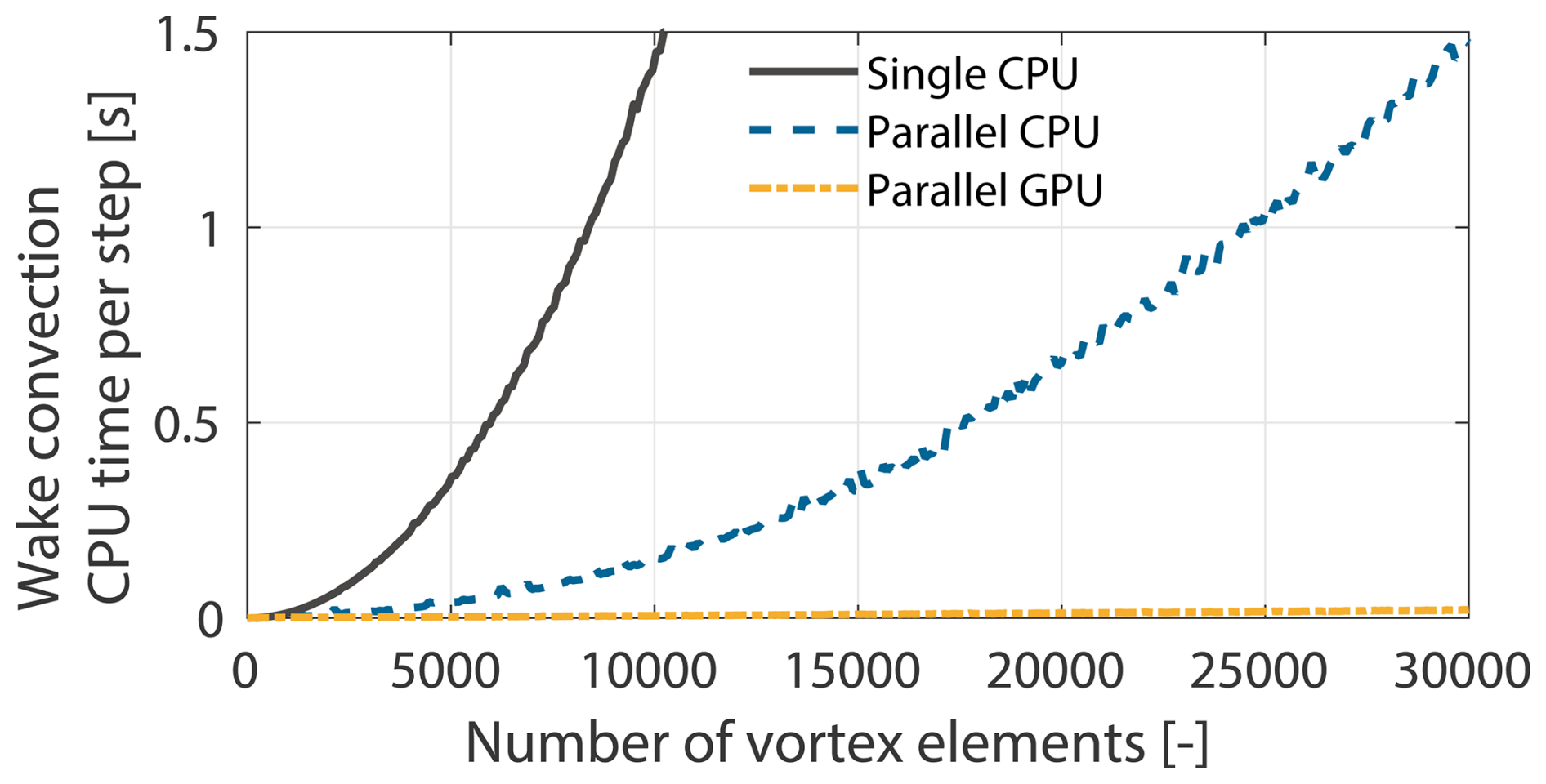
In Eq. (3), xp is the location where the induced velocity is being evaluated, x is the position vector of any given vortex element and dl is an arc segment of a vortex element. Solving the Biot–Savart law makes this method more computationally demanding than the BEM method because the full wake is taken into account when evaluating the induced velocity at a given position. Thus, to evaluate the induced velocity at a blade section, the contribution of each wake element must be calculated explicitly. Furthermore, to convect the wake nodes, the local induced velocity at each node is calculated to determine the convection velocity. This treatment allows the wake to develop freely but also results in a computational complexity that scales quadratically with the number of vortex elements, i.e., an 𝒪(N2) problem. In QBlade, an OpenCL-based GPU parallelization of the Biot–Savart evaluations enables a considerable decrease in computation time. Each vortex element is encoded into OpenCL vector primitives and distributed across a large number of GPU cores (Marten, 2020). As shown in benchmark tests in Fig. 2, the GPU implementation is about 2 to 3 orders of magnitude faster compared to a single-core CPU evaluation, making it viable for load simulations and design studies.
2.4 Structural model in QBlade
With the ever-increasing sizes of wind turbines, the method used to capture the structural dynamics of a wind turbine and in particular the blades is critical for accurately predicting aeroelastic loads. This is especially true for FOWTs, where the coupling between aerodynamic forces and the structural response is amplified by platform motions and low-frequency excitations. The latest generation of open-source research wind turbines (the IEA Wind 22 MW offshore reference wind turbine) underlines the importance of the structural model, since during its design, a link between the flapwise bend and torsional degrees of freedom, often referred to as bend–twist or shear–twist coupling, was considered to passively reduce the loads in high-thrust-operation conditions (Zahle et al., 2024a). In order to accurately capture this effect, the structural model of a simulation tool should ideally resolve the coupled dynamics between bending, shear and torsion along the blade span (Stäblein, 2016).
The current state-of-the-art for modeling a structural wind turbine is to assemble it in a multi-body formulation in which the tower and the three blades (in some codes also the drive train) are connected via joints and constraints (Guo et al., 2024). While outlining the development of yet another multi-body framework, Guo et al. (2024) give a good overview of available structural solvers in wind turbine simulation tools and their assumptions. One distinction between all the FEA models is the beam model in the multi-body formulation. OpenFAST can rely on either the ElastoDyn (NREL, 2025b) or the BeamDyn (NREL, 2025a) modules. The former evokes Euler–Bernoulli beams but assumes a set of prescribed degrees of freedom through a modal representation. This requires a pre-processing step to obtain best-fit sixth-order polynomials for the mode shapes (Jonkman and Buhl, 2005). The structural motion is then represented as a superposition of these pre-computed modes, which considerably reduces the overall system degrees of freedom and increases numerical efficiency. However, ElastoDyn neglects the torsional degree of freedom, which limits its ability to capture coupled bending–torsion effects (Bortolotti et al., 2024). BeamDyn, on the other hand, uses geometrically exact beam theory (Hodges, 2006). However, its computational speed makes it currently unfeasible for optimization or design tasks.
2.4.1 Multi-body representation in QBlade
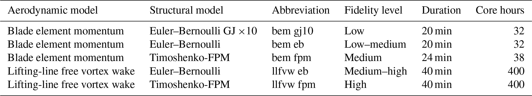
QBlade, like OpenFAST, models the turbine structure as a multi-body system. In order to do so, the open-source multi-physics engine Project::Chrono (Tasora et al., 2016) is integrated with the code. Each blade is discretized using a series of 1D beam elements arranged in a co-rotational formulation, enabling the accurate capture of large displacements and nonlinear geometric effects (Marten, 2020). Unlike in ElastoDyn, the torsional degree of freedom is available. To resolve the influence of shear and anisotropic composite behavior, QBlade accommodates multiple beam models, namely Euler–Bernoulli, Timoshenko and Timoshenko-FPM. The Timoshenko-FPM beam resolves all 6 degrees of freedom with full cross-couplings in the mass and stiffness matrices. This enables the representation of complex structural behaviors, such as bend–twist and shear–twist coupling, which are mechanisms considered in the design of modern wind turbine blades (Zahle et al., 2024a) and can alleviate ultimate and fatigue loads (Stäblein, 2016). The computational overhead of using Timoshenko-FPM beams in QBlade is modest, making it suitable for computationally intensive tasks such as optimization and design studies. This work leverages the integration of SONATA into QBtoWEIS to investigate how the choice of beam model, together with the choice of wake model, influences the sizing of the floating platform and the controller parameters. Table 1 provides a summary of the aerodynamic and structural models discussed in this section, which helps to interpret the results presented in this work (Sect. 4), along with their main assumptions.
Table 1Overview of aerodynamic and structural models implemented in QBlade that form the basis of the optimization studies.
3.1 Optimization problem
To assess the impact of aeroelastic modeling fidelity on MDAO, an optimization problem for the IEA Wind 22 MW offshore RWT mounted atop the semi-submersible floating structure that builds on the architecture of the VolturnUS-S platform (Zahle et al., 2024a) is formulated. As shown in Fig. 3, the platform consists of a center column that connects to the tower and three further outer columns, all connected via cylindrical members.
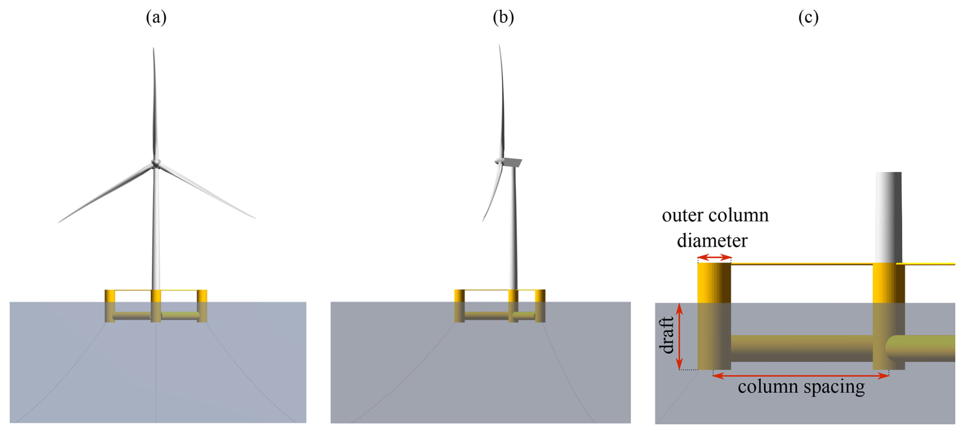
Figure 3IEA 22 MW RWT baseline configuration, rendered in QBlade. (a) Front view, (b) side view and (c) design variables of the floating substructure.
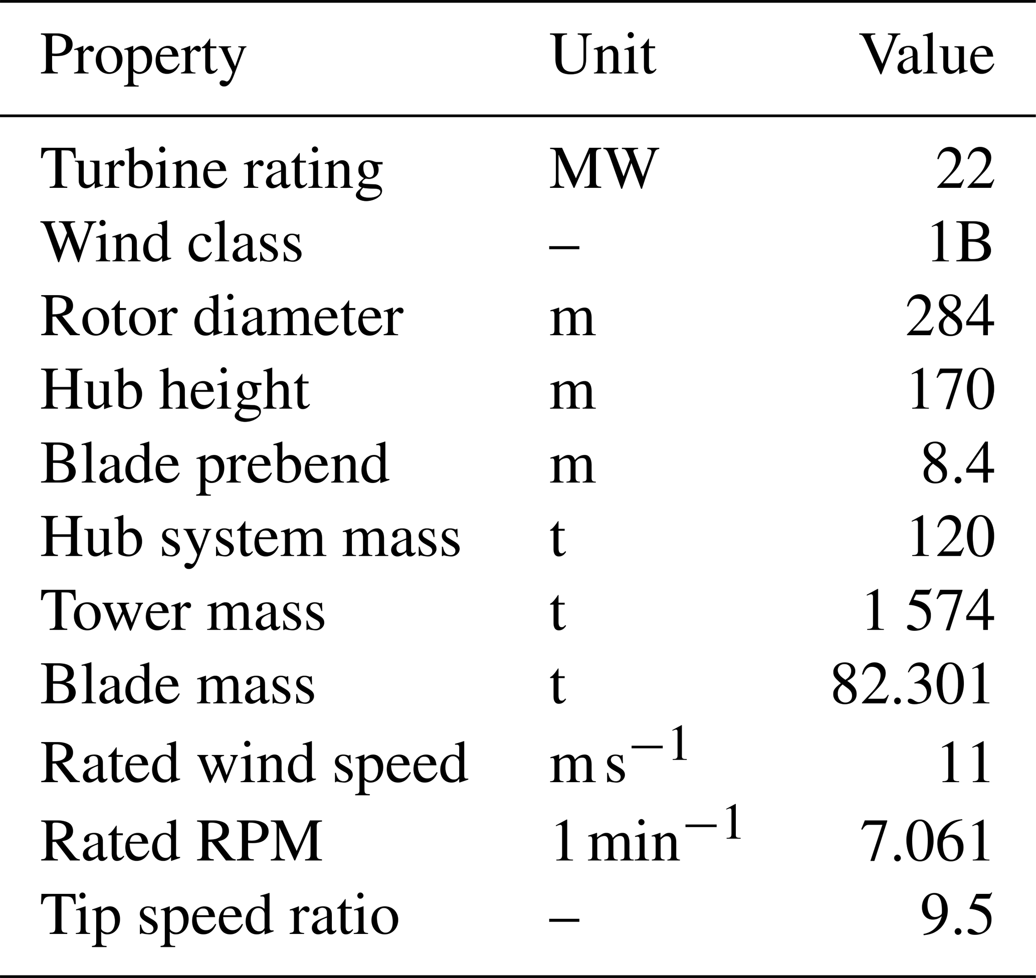
Table 2Main system properties of the IEA 22 MW RWT; see Zahle et al. (2024a) for a complete definition.
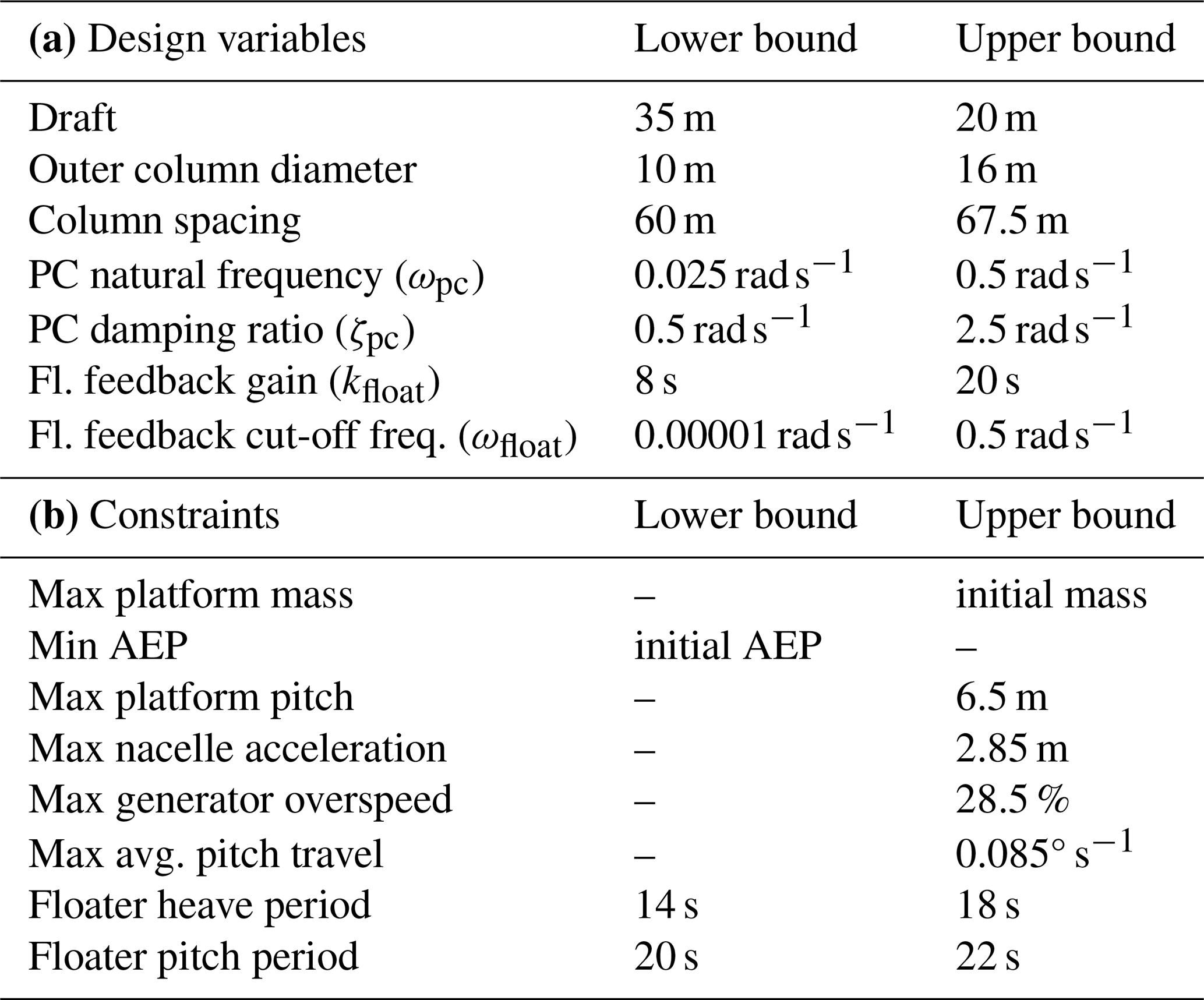
The optimization problem is inspired by the problem defined by Zalkind and Bortolotti (2024) and aims to minimize damage equivalent loads (DELs) at the tower base by varying geometric parameters of the floating substructure and tuning parameters of the turbine controller, under a set of constraints. This design problem was selected as a representative multidisciplinary case. Wind turbine rotors and substructures are often designed in isolation from one another, frequently by different companies relying on separate tool chains. In this case, the exchange of information between these tools is limited to high-level data, such as global load envelopes, thrust coefficients and interface forces, rather than detailed time-dependent aeroelastic responses. Moreover, the impact of rotor aeroelastic modeling fidelity in substructure design is often disregarded. For this reason, this work aims to investigate how different levels of rotor aeroelastic fidelity influence the overall design optimization of floating offshore wind turbines, with particular attention to the coupled rotor–substructure dynamics. Controller optimization is included in the design space since the baseline controller settings may not remain stable when the platform geometry changes. Inappropriate tuning could cause or amplify resonance effects and ultimately increase tower-base DELs, even if the substructure geometry is improved. In addition, including the controller enables exploration of design configurations that might otherwise be infeasible or sub-optimal if the control system remained fixed. More specifically, as shown in Table 3, the optimizer can vary the platform draft, outer column diameter and column spacing. The remaining design variables belong to the pitch control subsystem of the servo-controller. These include the floating feedback gain, kfloat and the low-pass-filter cut-off frequency ωfloat, which mitigate the negative aerodynamic damping problem (Skaare et al., 2007; Jonkman, 2010; Larsen and Hanson, 2007) through parallel compensation logic (van der Veen et al., 2012; Abbas et al., 2022). To briefly summarize the logic, the tower-top acceleration is low-pass filtered and integrated to generate a noise-reduced estimate of the tower-top velocity. This signal is then scaled by the gain kfloat and fed back to the pitch controller. Also part of the optimization are the closed-loop bandwidth of the pitch controller ωpc, which determines how quickly the controller responds to disturbances, and the damping ratio ζpc, which characterizes how oscillations in the closed-loop system decay. Both ωpc and ζpc have three control points at wind speeds of 12, 17 and 23 m s−1, allowing the pitch controller's behavior to vary across region III.
The multidisciplinary workflow used to evaluate each design is summarized in the extended design structure matrix (XDSM) diagram of Fig. 4. Because varying the aeroelastic fidelity required only modifications to the QBlade turbine definition, the workflow remains identical across all cases except for changes to either the structural beam model (“BEAMTYPE”) or the aerodynamic wake model (“WAKETYPE”) under the QBlade object within the modeling options of the WEIS problem definition. This setup allows for a controlled comparison of the influence of aeroelastic fidelity on the optimization results, with all other components of the loop unchanged. In this way, any differences in the optimal solutions can be attributed to the fidelity level of the aeroelastic model.
As shown in Fig. 4, the constraint optimization by linear approximation (COBYLA, Powell, 1994) is used.1 The optimizer updates the design variables and starts an analysis chain. The platform geometry is assembled, component properties (e.g., blade structure, platform mass) are derived, and steady-state Cp–Ct–Cq surfaces are generated in WISDEM and SONATA. The controller is tuned in ROSCO, and the aero-servo-hydro-elastic simulation in QBlade is run using either BEM or LLFVW models and Euler–Bernoulli or Timoshenko-FPM beam representations. The resulting time series are post-processed in pCrunch (NREL, 2025h) to compute tower-base bending moment DELs and evaluate constraints (e.g., platform pitch, annual energy production (AEP), platform heave or pitch periods), which are returned to the optimizer to close the loop.
3.2 Modeling considerations
The QBlade models used in the optimizations discussed in this work were identical; only chosen wake and beam models differed between them. The floating substructure model was derived from the windIO definition provided by Zahle et al. (2024b) and was assumed to be rigid. Furthermore, the strip-theory approach described in Zahle et al. (2024a) was applied, and the hydrodynamic coefficients (Ca, Cd and Cp) were set accordingly. In order to verify the natural frequencies of the assembled FOWT and its dynamic response to wave excitation, Fig. 36 of Zahle et al. (2024a) was used. The response amplitude operators (RAOs) were derived from QBlade simulations using white-noise waves, following the procedure described by Ramachandran et al. (2013). The tower was modeled as a flexible structure with Timoshenko beam elements. In order to reduce the influence of transients, the initial conditions for all wind speed bins were set to an 11 m surge displacement and a 1° platform pitch angle, which proved to be a suitable initialization for all cases. Initial rotational speed and blade pitch are wind speed specific and are provided by the WISDEM module RotorSE. The OYE dynamic stall model was activated with a time constant of τ=8. Regarding hydrodynamics, distributed buoyancy was enabled, the MacCamy–Fuchs correction was applied and Wheeler stretching was selected. The wave field was discretized into 500 linear wave components with equal frequency spacing. Design load case (DLC) 1.1, which is based on the IEC standards (International Electrotechnical Commission, 2019), was used for a class IB turbine. Metocean conditions corresponding to an offshore location west of the Isle of Barra in Scotland (Papi et al., 2022), which are particularly rough offshore conditions, were used to define the sea state under normal conditions. The operating range of the wind turbine was covered with 10 wind speed bins2, and for each wind speed, 6 seeds were simulated, resulting in 60 simulations per iteration. To reduce the influence of transients, a 250 s transient time was defined. The analysis time for each simulation was 600 s, resulting in 850 s total simulated time per simulation. All results shown in this work used QBladeEE v2.0.9 and QBtoWEIS v1.1.0.
3.3 Computational considerations and infrastructure
Since QBtoWEIS is parallelized, the number of simulations per iteration can be set without significantly impacting the overall runtime, as long as sufficient central processing unit (CPU) cores and GPUs are available. This is particularly the case for BEM simulations, which are only evaluated on the CPUs. In contrast, LLFVW simulations rely on GPUs, and oversubscribing to a single device can significantly increase computational time. Hence, for this work, a limit of 60 simulations per iteration was applied to limit overall runtime. BEM simulations were executed on the CPU CLX partition at the national high-performance computing center at the Zuse Institute Berlin (NHR@ZIB). Each compute node is equipped with two Intel Xeon Cascade Lake Platinum 9242 processors, with 96 compute cores and 384 GB RAM. LLFVW simulations were run on the GPU A100 partition at NHR@ZIB, which consists of nodes with two Intel Xeon Ice Lake Platinum 8360Y processors (72 cores in total), 1 TB RAM and four NVIDIA A100 GPUs (80 GB HBM2 each). The physical time per iteration for a given aeroelastic model combination, as well as the corresponding charged core hours per node, can be found in Table 4.
Table 4Aeroelastic model combinations, corresponding fidelity levels and charged core hours per iteration on the NHR@ZIB HPC. Table 1 provides an overview of the underlying aerodynamic and structural modeling approaches and their influence on the simulation.
This section presents and analyzes the results of the main optimization problem, which is aimed at reducing the damage equivalent loads at the tower base.3 The problem is run with five different aeroelastic model fidelity combinations (see Table 4) to assess their influence on optimization outcomes. The first combination, which constrains the torsional degree of freedom, represents the lowest level of aeroelastic fidelity and corresponds to the current implementation of OpenFAST with ElastoDyn in WEIS. Subsequent combinations increase the aeroelastic fidelity incrementally to evaluate their influence on the optimization outcomes. This analysis is followed by a discussion in Sect. 4.3, which introduces a variation in the optimization problem with the levelized cost of energy as a merit figure. This alternative formulation was motivated by initial findings, which suggested that it could provide additional value to this work.
4.1 Baseline comparison
Before the optimization results are analyzed, a statistical comparison of the results from the baseline (iteration 0) is provided in the following two sections to highlight differences caused by the varying levels of aeroelastic model fidelity on the same FOWT.
4.1.1 Statistical comparison
Figure 5 displays statistical metrics across different levels of aeroelastic fidelity for the baseline iteration. Each color represents a distinct fidelity level. The horizontal bars indicate mean values, the vertical lines represent the standard deviation, and the upward and downward triangles reflect the maximum and minimum values observed across all six seeds for a given wind speed bin. The low-speed shaft force in the downwind direction (a), which serves as a measure of total rotor thrust, reveals clear discrepancies between the fidelity levels, which can be traced back to modeling fidelity. Several tendencies are consistent within regions II and III of the power curve:
- i.
Cases with torsion-constrained or full Euler–Bernoulli beam models (*EB and GJ10) consistently show higher mean thrust levels compared to those with a Timoshenko-FPM beam.
- ii.
Cases using the LLFVW model show reduced variation (i.e., smaller standard deviations and min–max ranges).
- iii.
Cases using the LLFVW model show higher thrust levels relative to BEM simulations using equivalent beam models.
- iv.
In region III, results across all fidelity levels align more closely.
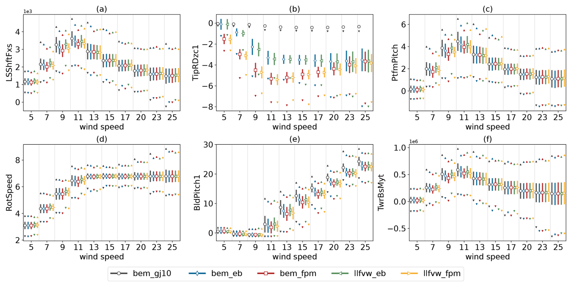
Figure 5Comparison of statistical metrics for the baseline configuration (iteration 0) of each fidelity level. (a) Low-speed shaft force in the downwind direction (kN), (b) rotation of blade tip (°), (c) pitch angle of the platform (°), (d) rotational speed (1 min−1), (e) blade pitch angle (°), and (f) tower-base fore–aft moment (kNm). For the sake of readability, the maximum values for subplot (b) are not shown.
The cause for (i) can be traced back to blade twist behavior, as shown in subfigure (b). The tip of the blade for the GJ10 model undergoes almost no twist. In contrast, the Euler–Bernoulli beam models show a steady increase in twist (towards feather) up to rated wind speed at a mean value of around 3.5°. Since cross-coupling terms are not included in this beam model, the rotation stems from aerodynamically induced torsion and the moment induced by the offset between the center of mass and the elastic center of the section. The FPM-based models show a larger tip rotation of up to 5.5°, before decreasing back to approximately 3.5° in region III. This increased rotation around rated wind speed can be attributed to shear–twist coupling, caused by the interaction between torsional and flapwise–shear degrees of freedom captured in the Timoshenko-FPM beam representation. As a consequence of varying spanwise twist between the levels of fidelity, the local angle of attack is larger in models with reduced twist. A higher angle of attack, in turn, leads to larger aerodynamic forces in both the tangential and the normal directions, which results in increased thrust and torque. Furthermore, the reduced variation observed in the LLFVW cases (ii) is a phenomenon often reported in the literature. For a detailed analysis, the interested reader is referred to Perez-Becker et al. (2020) and Boorsma et al. (2020). In the context of FOWTs, recent studies have focused on differences between BEM and LLFVW methods in load amplitudes under fore–aft oscillations of the rotor (Bergua et al., 2023; Papi et al., 2024a; Schulz et al., 2025). A common finding is a reduced load amplitude of the thrust force when the LLFVW method is used instead of the BEM method, which is ultimately attributed mostly to dynamic inflow effects. To capture this effect, BEM methods require empiric dynamic inflow correction models (Mancini et al., 2023). Concerning (iii), the LLFVW method tends to predict lower overall rotor induction compared to the BEM method, leading to higher axial wind velocities in the rotor plane. As a result, the controller's wind speed estimator drives the system toward a higher rotational speed in order to maintain an optimal angle of attack. This in turn leads to increased aerodynamic loading and hence larger thrust forces. Finally, the reduced difference between models in region III is due to pitch controller activation above rated wind speed. Here, the pitch controller prevents the rotational speed from overshooting the rated speed and reduces the aerodynamic force by pitching towards feather. As shown in subfigure (e), the torsion-constrained bem gj10 model requires the highest blade pitch angles, followed by the Euler–Bernoulli beam models and finally the ones with Timoshenko-FPM beams. For an equivalent beam model, the LLFVW cases require more pitch actuation than their BEM counterparts, again reflecting the higher aerodynamic loading described earlier. However, pitch standard deviation is lower in LLFVW simulations. Platform pitch and tower-base fore–aft moments (subfigures c and f) are strongly correlated with rotor thrust and, above region III, blade pitch.
4.1.2 Time-domain analysis
Figure 6 presents a selection of channels from a full run of a single seed at an 11 m s−1 average wind speed. This operating point is well suited to compare the different cases, as the wind speed frequently crosses the rated threshold, triggering transitions between torque and pitch control. Within the shown time window, the wind velocity dips noticeably below rated on three occasions (around 400, 550 and 700 s), each time causing the generator torque (subplot e) to drop from its rated value. Two trends emerge:
- i.
Simulations using the BEM wake model exhibit a stronger torque reduction compared to the LLFVW cases and require more time to recover to rated torque.
- ii.
With the aerodynamic wake method equal, the Timoshenko-FPM beam structural models generally produce lower torque than their EB counterparts.
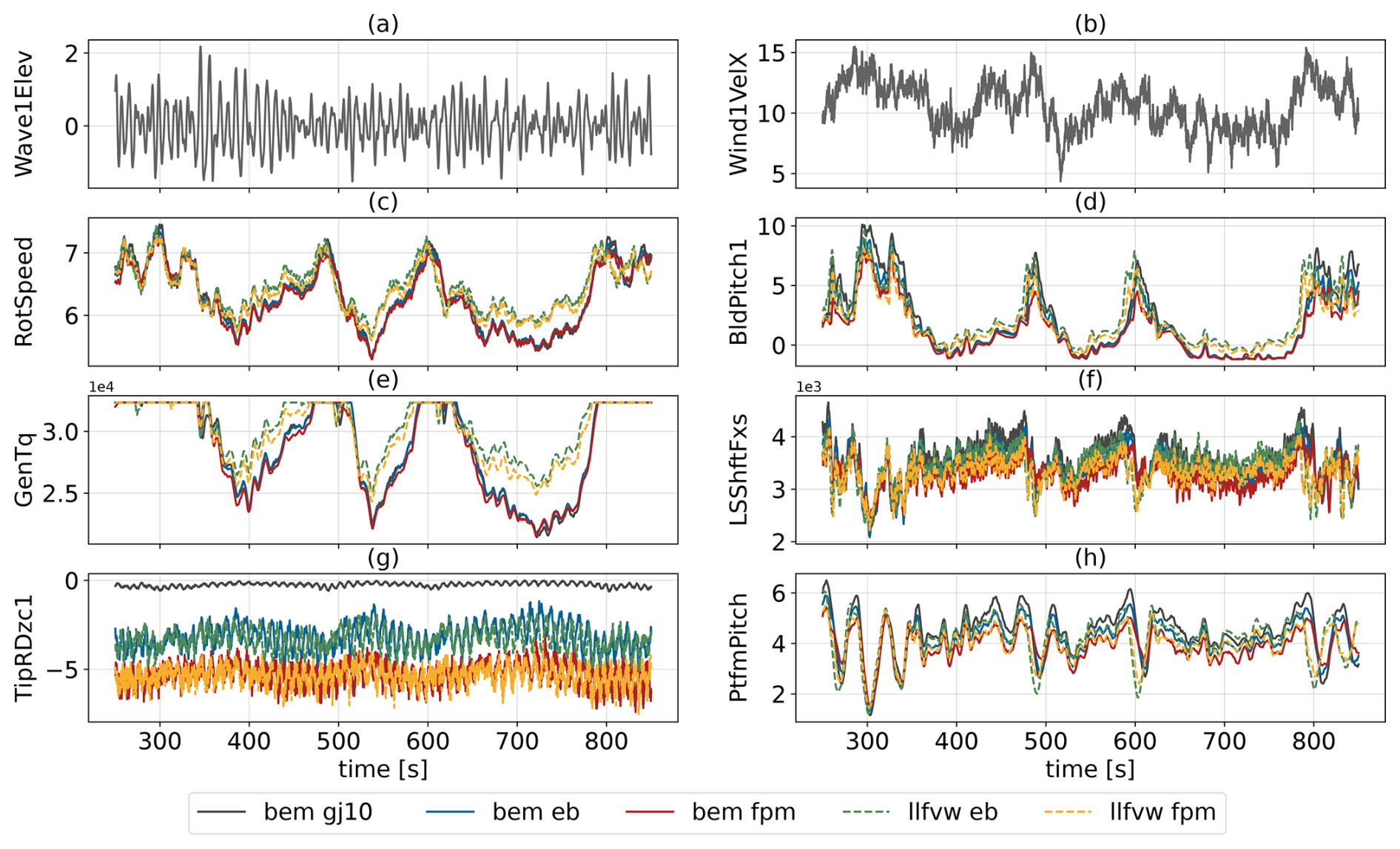
Figure 6Comparison of baseline time series for different fidelity levels for one seed at 11 m s−1. (a) Wave elevation at reference point (m), (b) wind velocity at hub height (m s−1), (c) rotational speed (1 min−1), (d) blade pitch angle (°), (e) generator torque (kNm), (f) low-speed shaft force in downwind direction (kN), (g) rotation of blade tip (°) and (h) pitch angle of platform (°). The metocean conditions in subfigures (a, b) are identical across cases and therefore not color-coded.
The first trend is consistent with the differences in axial induction predicted by the two wake methods, as discussed in Sect. 4.1.1. The second is due to blade twist behavior (subplot g), where the respective beam model affects the torsion at the blade tip. The blade pitch time series (subplot d) shows actuation whenever wind speed exceeds rated. As expected, the LLFVW cases initiate pitching slightly earlier, in line with their earlier recovery of generator torque to rated levels. Further, a small offset is visible between the LLFVW and BEM cases, which persists even during periods where blade pitch nears its saturation angle (e.g., around 700 s). Finally, the thrust and platform pitch responses (subplots f and h) reflect the aeroelastic fidelity effects identified previously:
- i.
LLFVW models predict higher thrust than BEM models.
- ii.
EB models predict higher thrust than FPM models.
- iii.
The torsion-constrained GJ10 case yields the highest thrust among all.
4.2 Convergence trends
This section presents the convergence trends of the optimization process, focusing on the merit figure, constraints and design variables.
4.2.1 Merit figure
Figure 7 shows the convergence trends of the tower-base bending moment DELs, which is used as the merit figure. All fidelity levels achieve a substantial reduction in DELs at the tower base over the optimization process, though the final achieved optima vary. The bem gj10 model converges to the least favorable solution in terms of percentage point reduction, while the bem eb model settles slightly lower. The remaining three configurations (bem fpm, llfvw eb and llfvw fpm) achieve the largest relative reductions of approximately 12.5 %–13.1 %. This trend suggests that increasing aeroelastic fidelity not only improves the accuracy of load prediction but also enables more effective optimization.
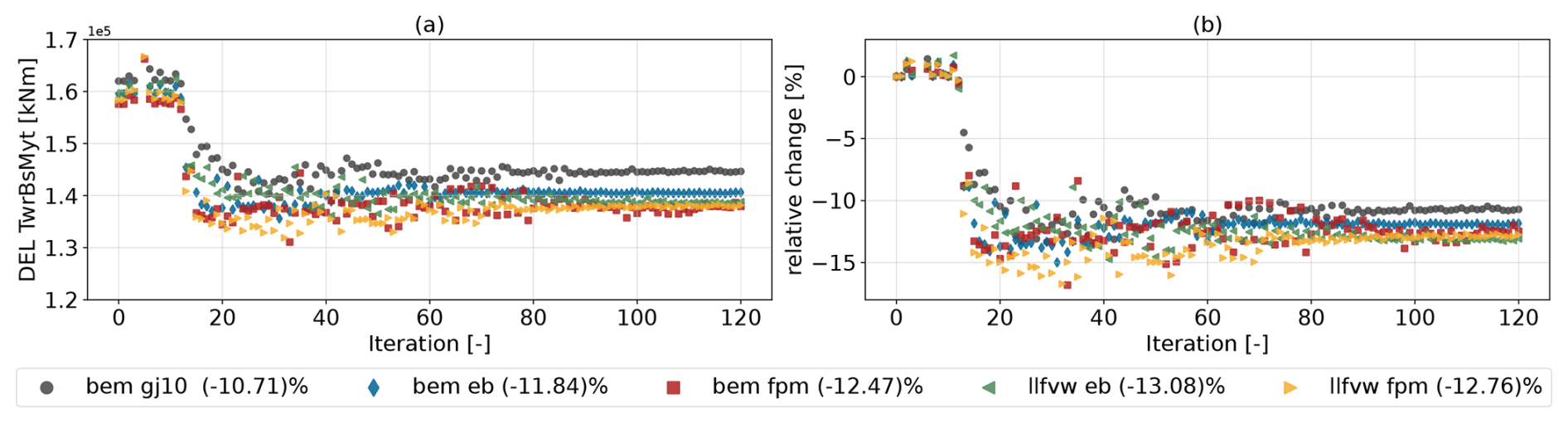
Figure 7Convergence of the tower-base bending moment DEL. Panel (a) shows the absolute DEL values and (b) the relative change in each fidelity level with respect to its initial iteration. The maximum iteration limit was set to 120, where all optimizations appear to have converged.
4.2.2 Design variables
Figure 8 shows the convergence trends of the feedback gain and low-pass-filter cut-off frequency of the parallel compensation logic. For the feedback gain (Fig. 8a), the optimizer generally converges to values close to the initial guess of 10 s, with the bem gj10 model reaching the largest gain and the remaining models converging to similar values. The low-pass-filter cut-off frequency (Fig. 8b) indicates an increasing trend towards a value of around 0.4 rad s−1 (corresponding to ≈0.064 Hz) for all models. Figure 9 shows the values of the three control points for the pitch controller bandwidth ωpc and damping ratio ζpc (a and b) at the optimal iteration, as well as the optimized gain schedules for the proportional kp,pc and integral terms ki,pc of the collective pitch controller across the wind speed range (c and d). Generally, higher natural frequencies ωpc reduce the rotor's response time, while larger damping ratios ζpc reduce the number of oscillations during the response (Abbas et al., 2022). The proportional gain schedule, which depends on both ωpc and ζpc, stands out for the bem gj10 case with larger absolute gains compared to the other fidelity levels, which otherwise converge to a relatively close solution. The integral gain schedule, depending solely on ωpc, reveals a difference at high wind speeds, where the bem gj10 case shows a notable increase for above rated wind speeds, while the remaining fidelity levels maintain a flatter profile. As detailed by Abbas et al. (2024), high damping ratios allow for higher proportional gains and can help satisfy the overspeed constraint. Since all controllers were optimized with the same objective of minimizing tower-base DELs, the resulting control parameters represent the optimal solution for a given platform, simulated with the given aeroelastic fidelity level. Similar to the conclusion drawn by Zalkind et al. (2022) for platform-to-platform comparisons and the influence of a given platform type on the design of a tower, this approach enables a fair assessment of how modeling fidelity affects the platform–controller design process. Therefore, differences in the converged solution of the physical system (also known as the floater), as presented in the following, can be attributed primarily to the influence of the aeroelastic fidelity on the optimization.
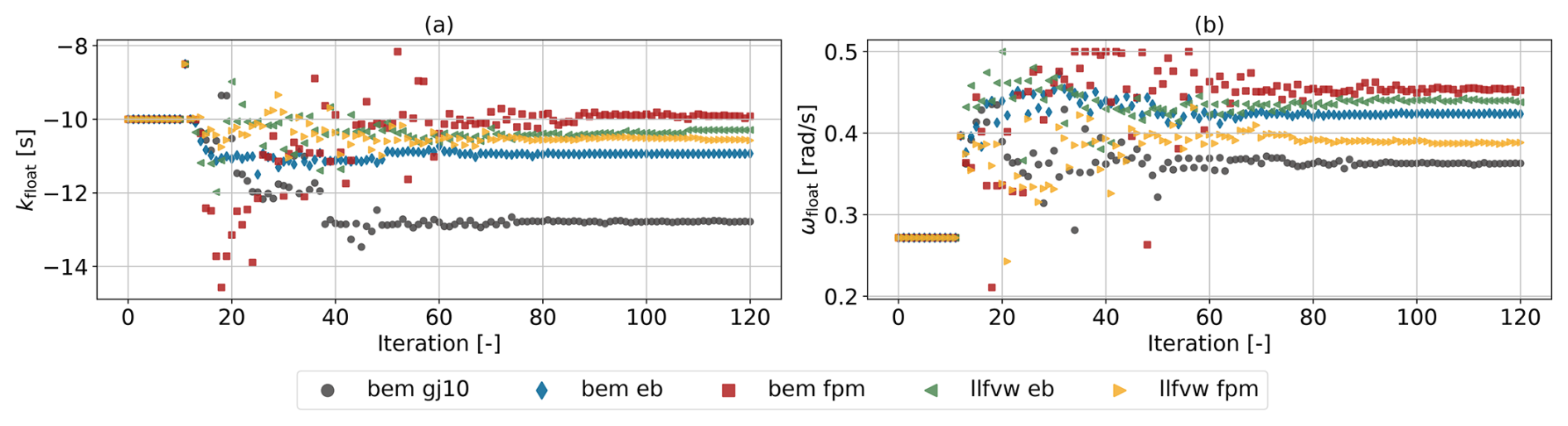
Figure 8Convergence trends of design variables impacting the parallel compensation logic of the pitch controller to avoid negative damping.
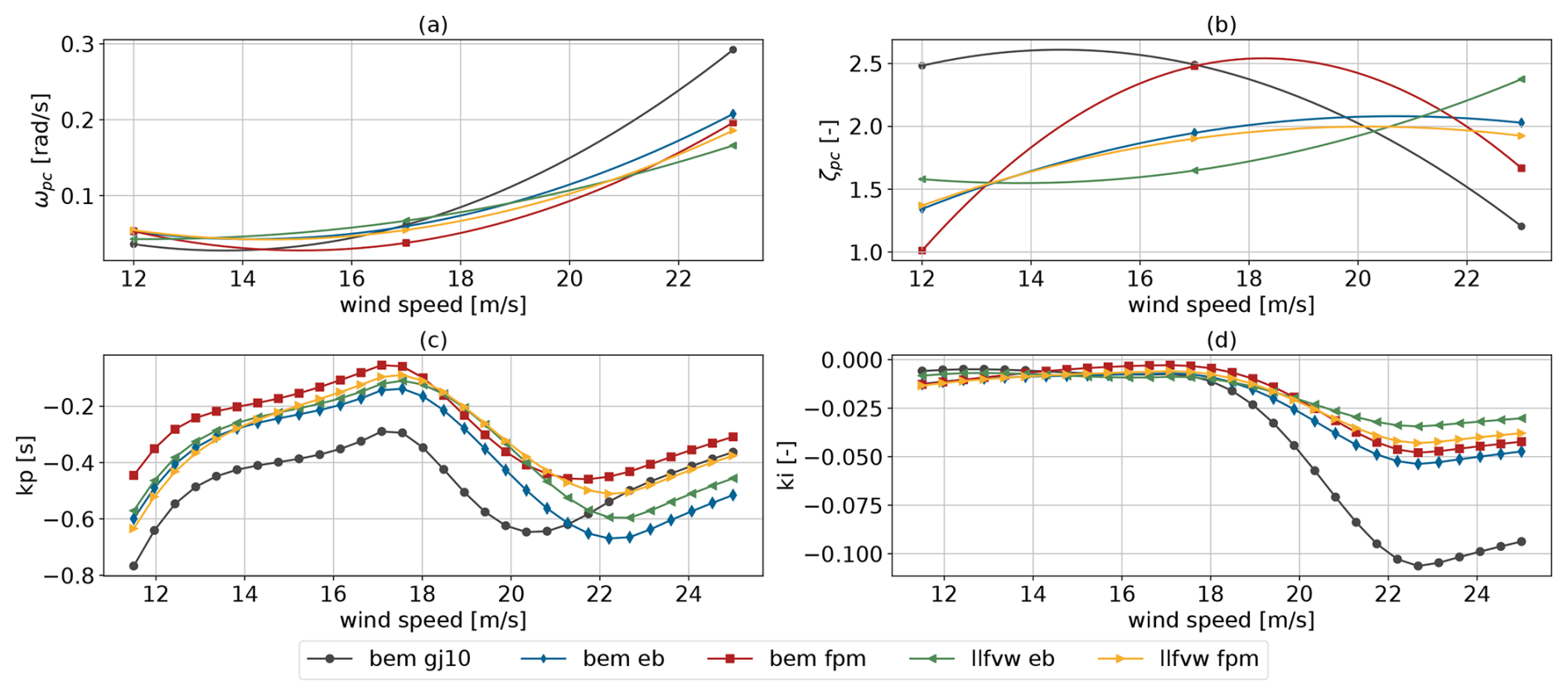
Figure 9Tuning parameters of the pitch controller (a, b) and the resulting proportional and integral gains (c, d) for the optimized designs.
Figure 10 shows the evolution of the design variables related to the physical dimensions of the floating substructure (a–c) and the resulting platform mass (d). The platform mass of the initial design was set as a constraint. As a result, any increase in one geometric design variable must be offset by a decrease in others in order to comply with this constraint. Across all fidelity levels, the optimizer significantly reduced the outer column diameter (subplot a). This trend can be explained by hydrodynamic considerations, where decreasing the water plane area reduces wave excitation and leads to lower dynamic loading. The bem gj10 model converged to the largest final diameter, approximately 40 cm above the others. The remaining models are closely matched, with both FPM-based models converging to slightly smaller diameters than their Euler–Bernoulli counterparts. In contrast, column spacing (subplot b) was increased in all cases, reaching the upper bound for all models except for llfvw fpm, which converged to a value approximately 1 m below that limit. Increasing the column spacing increases the hydrostatic restoring moment. This compensates for the reduction in the restoring moment caused by reducing the outer column diameter. No consistent trend is observed in the draft evolution (subplot c). It is worth stating that all configurations satisfied the platform mass constraint. The FPM-based models converged to lower mass levels than the EB-based ones. Interestingly, the llfvw fpm configuration resulted in the lowest final platform mass, implying that a more efficient structural layout is enabled by the higher-fidelity aerodynamic representation.
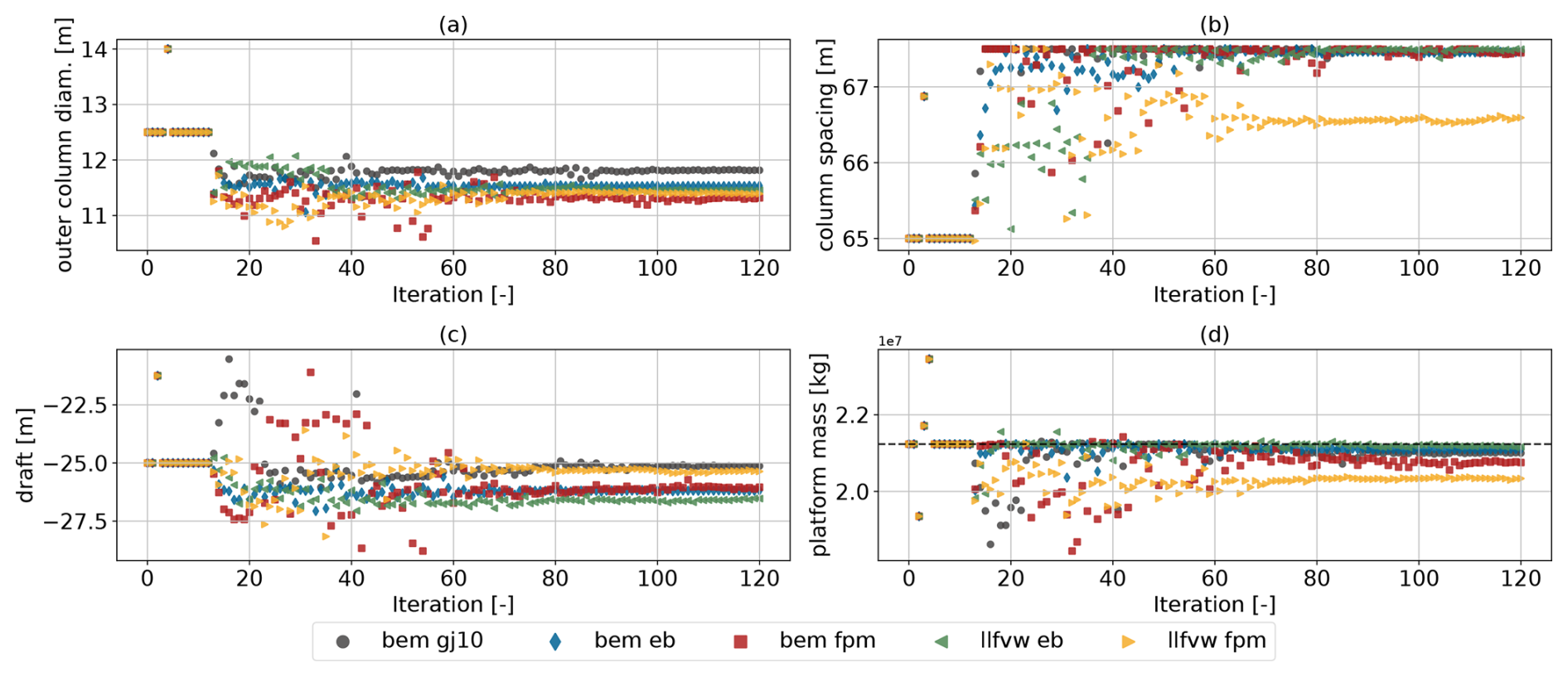
Figure 10Convergence trends of design variables impacting the dimensions of the floating substructure and the resulting platform mass.
Figure 11 presents the convergence trends for a selection of the constraints set for the optimization problem (see Table 3b for the complete list). The AEP is plotted in relative terms (subplot e), as each model starts from a different initial value. This respective initial AEP was imposed as a minimum constraint in each case to not allow the optimizer to trade a reduction in loads for a reduction in AEP. Subplot (f) shows the blade root flapwise bending moment DEL, which was not explicitly included in the optimization problem, but is shown to illustrate that the found solutions did not lead to an increase in blade loading. The generator overspeed (subplot b) and the maximum platform pitch angle (subplot d) constraints are active across all fidelity levels, and, in the case of bem fpm, the overspeed constraint is not satisfied within 120 iterations, rendering the solution infeasible. The average pitch travel constraint (subplot c) is active only for the torsion-constraint case (bem gj10). Here, the absence of twist-to-feather load alleviation (aerodynamic and structural) in this case leads to increased pitch actuation, making this constraint more design-driving in comparison to the other levels of fidelity. The maximum platform pitch constraint is primarily driven by the reduction in outer column diameter. While increasing column spacing (as discussed in Fig. 10) can offset the loss of the hydrostatic restoring moment from smaller columns, the effect of aeroelastic fidelity becomes evident, since platform pitch is directly driven by rotor thrust, and differences in predicted thrust between fidelity levels lead to different allowable column diameters.
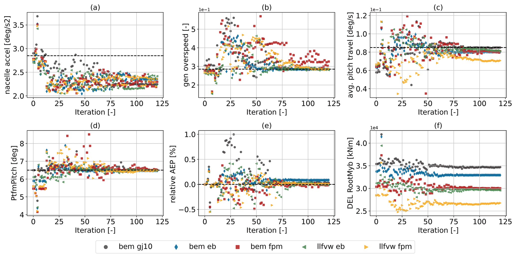
Figure 11Convergence trends of the most relevant constraints, along with the flapwise bending moment DELs at the blade root. Although the latter were not part of the optimization problem, they confirm that none of the five cases resulted in increased load levels for the blades.
4.2.3 Frequency-domain analysis
Figure 12 shows the power spectral densities (PSDs) for selected channels for the baseline (left column) and final iterations (right column) at an average wind speed of 13 m s−1. The power spectrum of the tower-base fore–aft bending moment (subplots a and b) is quite revealing concerning the energy at certain frequencies which were reduced by the optimizer. Focusing on the spectrum of the tower-base fore–aft moment for the baseline (subplot a), four distinct frequencies can be identified. The first one (from low to high frequencies) is present at the floater's natural pitch frequency (≈0.03 Hz). The next two frequency peaks lie within the linear wave frequency range and correspond to the excitation of the surge and pitch degrees of freedom by the linear waves. These modes are phase shifted and partially cancel each other out, which results in the characteristic two-peak shape. The last one sits around the 3P frequency of the rotor. In subplot b, the corresponding spectra to the final iterations, it can be observed that the peak at the natural floater pitch frequency is rendered nonexistent. This is achieved mainly through the tuning of the pitch control bandwidth (ωpc), where a reduced bandwidth at corresponding wind speeds seems beneficial. The corresponding PSDs of the blade pitch actuation (c and d) reveal no actuation within the natural floater pitching frequency in the optimized solution, which is in contrast to the baseline. Further, the energy within the first peak within the linear wave frequency range (0.05–0.1 Hz) is reduced by roughly half, while the second peak (0.11–0.16 Hz) remains largely unaffected. Given the multi-dimensional and nonlinear nature of the design space, it is difficult to draw definitive causal conclusions. However, the results indicate that this reduction is primarily achieved through a decrease in the water plane area. Hence, one can observe that the solution with the largest outer column diameter (bem gj10) undergoes higher excitation in this frequency. A further reduction, albeit a smaller gain compared to the reduction in the water plane area, within this frequency range can be explained by the blade pitch actuation (subplots c and d). Within the 0.05–0.1 Hz frequency range, slightly increased energy of blade pitch actuation is present in the final iteration – a result of the increased low-pass-filter frequency (see Fig. 8b). This leads to part of the wave excitation being dampened through the parallel compensation logic. This comes at a cost of increased platform pitching motion. Subfigures e–h are closely related to the blade pitch actuation; hence the peaks at platform natural frequency and the higher linear frequency range are reduced. Finally, the peak around the 3P excitation is also largely unaffected by the optimization.
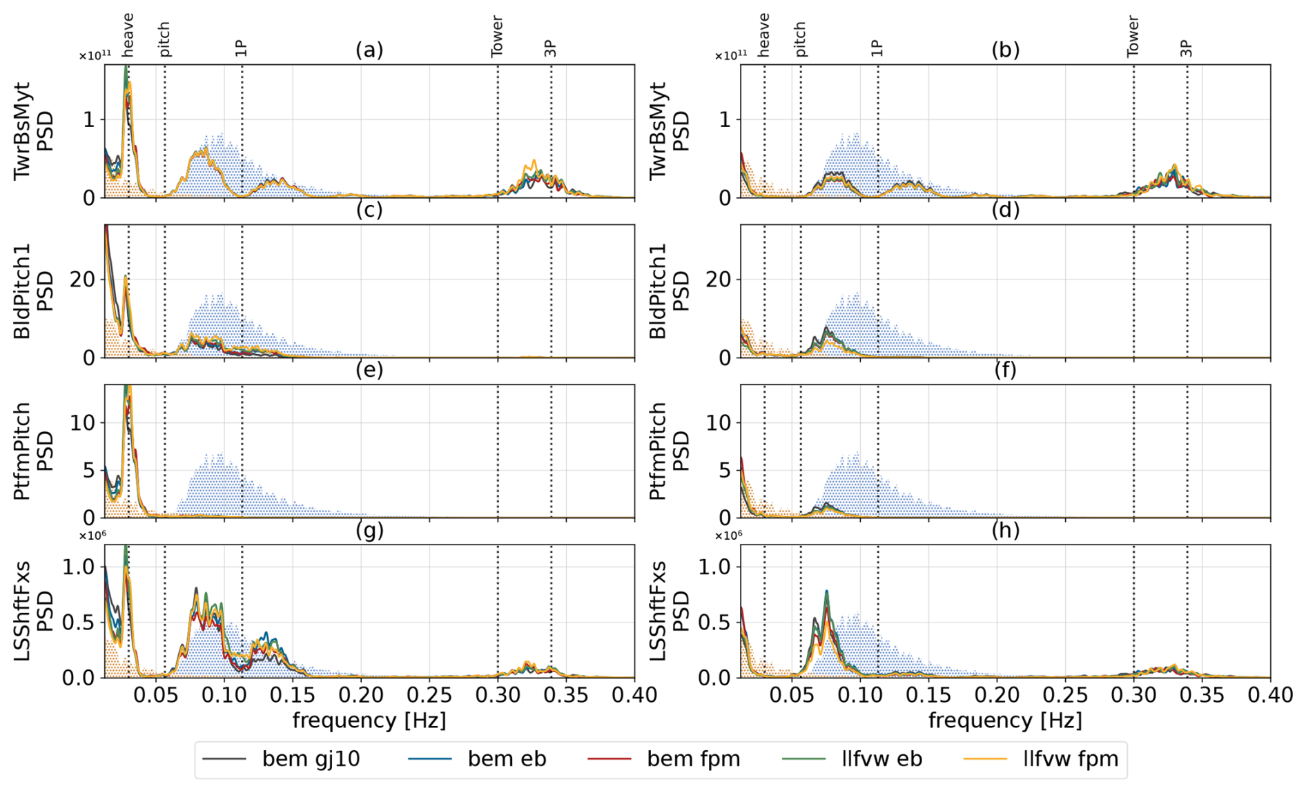
Figure 12Power spectral densities of selected channels for the baseline and final iterations. The left column corresponds to the baseline and the right column to the final iteration for each method. The spectra are obtained from concatenated time series across all six seeds at a wind speed of 13 m s−1. The dot-hatched areas represent the wind and wave spectra (scaled for visibility). The former is best seen between 0 and 0.05 Hz and the latter between 0.05 and 0.2 Hz. The dominant system natural frequencies are highlighted with dotted vertical lines.
4.2.4 Cross-evaluation of design outcomes
To conclude this section, the design resulting from each optimization was re-evaluated with every aeroelastic model listed in Table 4. This cross-evaluation allows for a fair comparison between designs as they are modeled with consistent modeling fidelity. Figure 13 summarizes these results. The groups on the x axis represent the evaluation fidelity level, while the colored bars depict the design outcomes from the corresponding optimization. Several trends are evident. In Fig. 13a, within each group (i.e., the five designs evaluated with the same fidelity model), the tower-base bending DELs generally decrease for designs found with increasing fidelity. This indicates that higher-fidelity optimizations identify designs that are favorable even when analyzed by lower-fidelity models. Figure 13b shows the maximum platform pitch constraint, which, as discussed above, strongly influences the design. As expected, the constraint is met when a design is evaluated with the same model used in its optimization (e.g., the bem of design when evaluated with the bem of fidelity level). Staying in the bem of group, when the other design outcomes are evaluated by bem of, this constraint is violated. Conversely, designs optimized with lower-fidelity models show more conservative behavior with regard to the platform pitch when re-evaluated with higher fidelity levels, e.g., in the llfvw fpm group, remaining well below the constraint.
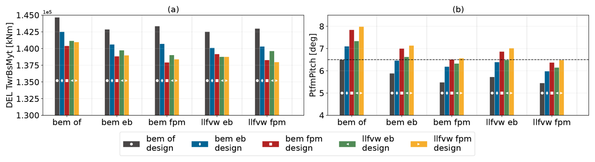
Figure 13Cross-evaluation of optimized designs found with different aeroelastic fidelity levels. Each group on the x axis is the evaluation model. The colored bars indicate the design outcomes for each fidelity level optimization. The dashed line marks the pitch constraint.
4.3 LCOE optimization
From the analysis so far, there seem to be advantages related to increasing the level of aeroelastic fidelity in the design stage. In the previous optimization setup, however, where tower-base loads were chosen as the merit figure and both AEP and platform mass were only treated as constraints, further reductions in mass or gains in AEP were not rewarded as long as the constraints were satisfied. As shown in Fig. 10, the llfvw fpm case not only achieved a sizable reduction in loads but also lowered platform mass more than the other cases. For this reason, the optimization problem was reformulated with LCOE as the merit figure instead of the tower-base bending DEL. In the LCOE optimization setup, the same design variables listed in Table 3a were used, while all constraints from Table 3b were applied except for the maximum platform mass and minimum AEP. These two constraints were removed to allow the optimizer to explore the most cost-effective trade-offs between platform cost and energy production. The convergence trends of LCOE and its main contributors are shown in Fig. 14. All cases increased AEP and reduced platform cost. As already discussed, the same initial design (iteration 0) leads to variations in predicted AEP between different fidelity levels (Fig. 14c). The main trends are that LLFVW methods predict increased AEP over the BEM methods. As previously mentioned, this is a result of the chain of events that originates with the induced velocities. LLFVW estimates smaller inductions than BEM. This increases the wind velocity in the rotor plane, leading the controller to increase the rotational speed in order to operate at an optimal tip speed. Ultimately, this results in an increase in mean thrust and, critically for AEP, torque (see Figs. 5 and 6). Furthermore, as discussed in Sect. 4.1.1, passive load alleviation (achieved through shear–twist coupling), which is only captured with the Timoshenko-FPM beams, affects AEP prediction and causes the observed differences in this metric. This carries through to the baseline LCOE values (Fig. 14a), which makes it difficult to draw fair comparisons between the five cases. A regression analysis of sensitivities of LCOE with respect to AEP and platform cost reveals that for a 1 % increase in AEP, the LCOE decreases almost 14 times more compared to a 1 % decrease in cost. Consequently, even slight discrepancies in AEP prediction have the potential to significantly influence the LCOE outcome and mask reductions in platform mass (see Appendix B). Platform cost, in contrast to AEP, is not influenced by aeroelastic fidelity in the baseline design. Here, the three BEM-based optimizations demonstrate larger reductions in platform cost as the fidelity of the beam type increases (5.4 % for GJ10, 6.0 % for Euler–Bernoulli and 6.8 % for FPM). The LLFVW-based cases achieved further reductions of 7 % and 8.3 % in platform cost respectively, also improving the result with increasing fidelity level of the beam type.
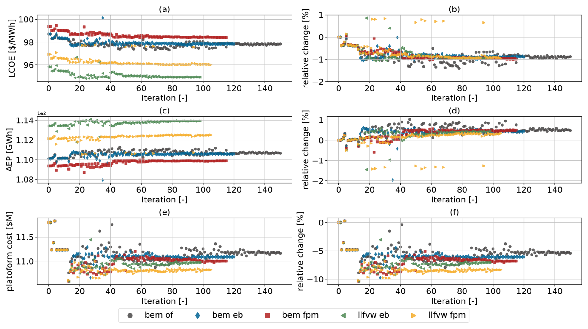
Figure 14Convergence trends of absolute and relative levelized cost of energy (a, b), annual energy production (c, d) and platform cost (e, f). For the bem gj10 configuration, the iteration limit was increased to 150, as convergence was not achieved within the initial limit of 120 iterations.
From Table 5, it is evident that all optimized cases reduced both the draft and the outer column diameter compared to the initial design. Notably, the draft reductions in the LCOE optimization (20.0–21.1 m) are more pronounced than in the tower-base bending moment DEL optimization (see Fig. 10c), where the draft remained near or increased relative to its initial value (25.1–26.5 m). This reflects the different optimization objectives. The LCOE optimization rewards mass reduction through lower material costs and finds a lever in this design variable. In contrast, the tower-base bending DEL optimization found that an increased draft was beneficial for load mitigation. On the other hand, column spacing varies between cases, which in turn drives the differences in platform mass. A key limiting factor was the heave period constraint (Fig. 15a), whose lower bound was active in all optimizations. This constraint was imposed to prevent the platform natural heave frequency from shifting towards the linear wave frequency range.
Table 5Initial and final design variable values defining the dimensions of the floating substructure.
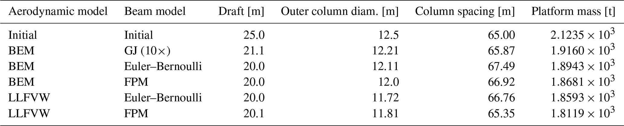
Table 6 lists the final design variables related to controller tuning. Across all cases, the floating feedback gain is reduced close to its lower bound (−8 s), while the low-pass-filter frequency (ωfloat) shows more variation between models. The bandwidth at wind speed control points 12 and 17 m s−1 is consistently reduced to lower values, while it is elevated at 23 m s−1. This mirrors the trends seen earlier in Fig. 8c, with the difference that this time bem eb, along with bem gj10 and llfvw eb to a lesser extent, pushes the bandwidth higher compared to the remaining cases. The presumable cause for reducing bandwidth at 12 and 17 m s−1 is that the pitch controller reacts more slowly to above rated rotational speed and thereby favors AEP, while increasing bandwidth at 23 m s−1 is a requirement to comply with the generator overspeed, which is a constraint that is active across all cases (Fig. 15b).
Table 6Initial and final values of design variables influencing the behavior of the pitch controller.
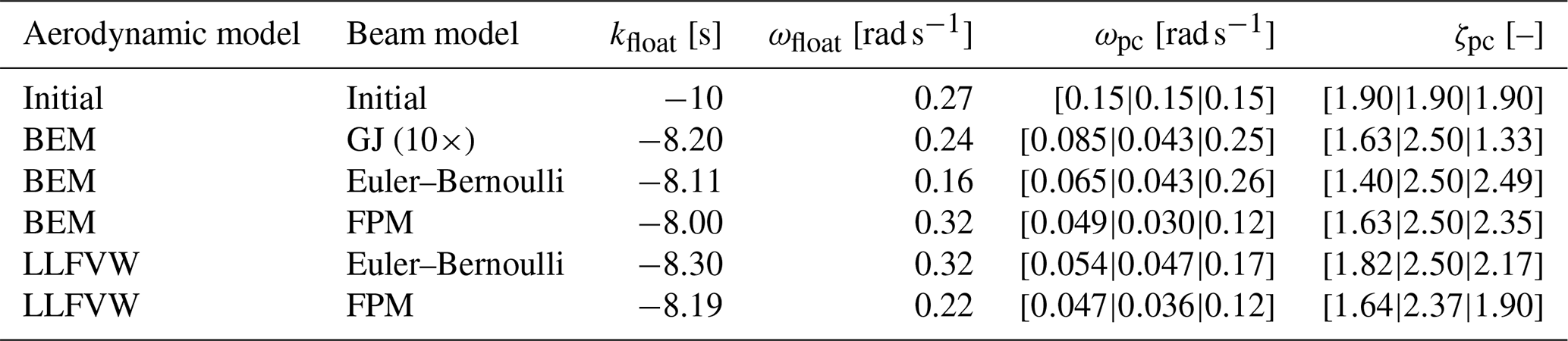
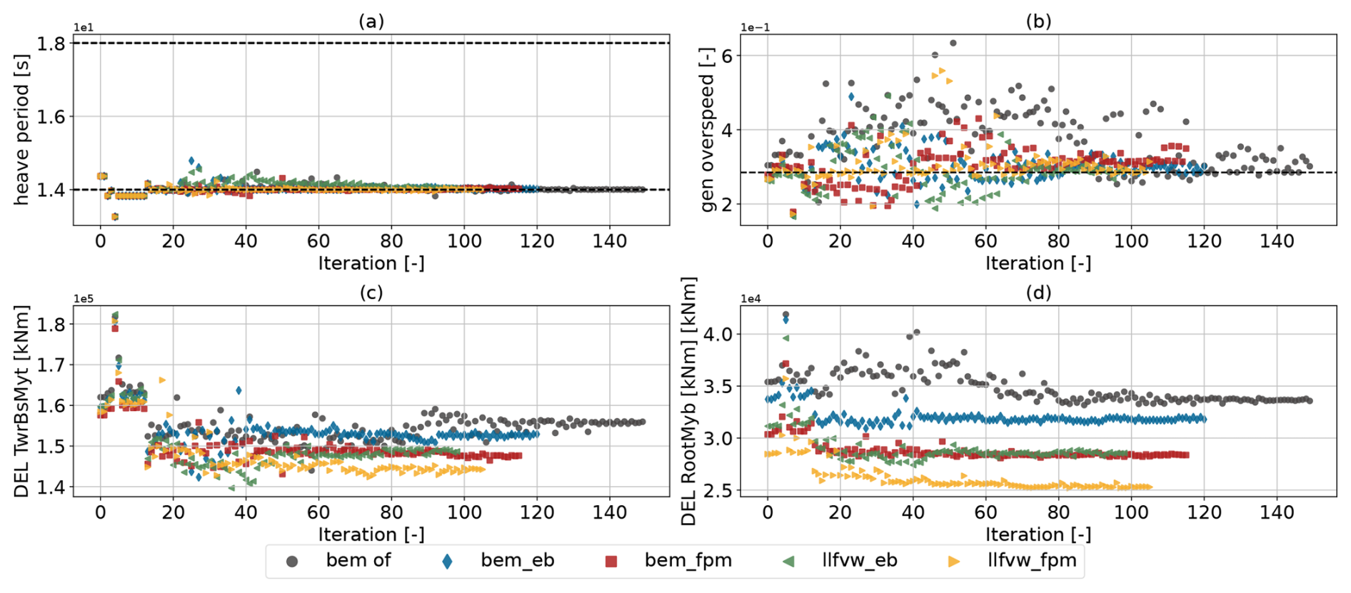
Figure 15Active constraints during the optimization with merit figure LCOE along with the tower-base and flapwise blade root bending moment DELs.
The overspeed constraint appears to be particularly limiting in cases involving beam models that cannot capture the effect of structural shear–twist coupling (GJ10 and EB) and less so for the cases with Timoshenko-FPM beams. One possible reason for this is that, during unsteady events such as gusts, the increased blade loading causes a blade modeled with Timoshenko-FPM beams to twist toward feather due to shear–torsion coupling. This eases the load, which reduces the requirement on the pitch controller to respond rapidly and enables an operation with lower bandwidth, benefiting AEP. In contrast, GJ10 and EB models do not resolve this mechanism, resulting in higher required controller bandwidth. Interestingly, the bandwidth tuning for the llfvw eb case falls between the FPM and EB models at the control point of 23 m s−1. This suggests that the choice of aerodynamic model also mitigates the overspeed constraint. Although it is somewhat surprising that the limited amount of wake-induced velocity influences controller tuning in these conditions with a low tip speed ratio, it is worth noting that the oscillation occurs within a reduced frequency range of 1–2.4 As laid out by Schulz et al. (2025), unsteady events in this reduced frequency range are primarily the dynamic wake effect and cause differences in rotor thrust amplitudes between BEM and LLFVW methods, with the latter predicting considerably smaller amplitudes.
Even though tower-base and blade root bending DELs were not part of the optimization problem, Fig. 15c and d clearly show that increasing the modeling fidelity again yields beneficial results. As the level of aeroelastic fidelity increases, both tower and blade loads display stronger reductions.
This work introduced QBtoWEIS, a novel framework that integrates the QBlade and SONATA tools into the WEIS co-design optimization framework for floating offshore wind turbines. This integration adds two new levels of aeroelastic fidelity to WEIS, namely QBlade's unsteady polar blade element momentum and lifting-line free vortex wake methods. QBlade also provides a multi-body structural solver that uses Euler–Bernoulli or Timoshenko beam elements, with fully populated mass and stiffness matrices that capture cross-couplings between degrees of freedom. To enable the integrated generation of 6×6 stiffness and inertia matrices from the blade layup definition in WindIO, the cross-sectional analysis tool SONATA was also integrated into WEIS. This allows aerodynamic and structural modeling fidelity to be systematically varied within control co-design optimizations of floating offshore wind turbines. A comparative design study was carried out using QBtoWEIS to investigate the impact of aeroelastic fidelity on the controller and substructure designs of a modern wind turbine on a semi-submersible platform. Two optimization problems were formulated, and each was run with five different combinations of aerodynamic and structural fidelity levels. The lowest fidelity level used a torsion-constrained Euler–Bernoulli beam model with unsteady blade element momentum theory, matching the capabilities in WEIS. Higher fidelity levels incorporated either Euler–Bernoulli beams with torsion or Timoshenko-FPM beam models, coupled with blade element momentum or lifting-line free vortex wake solvers.
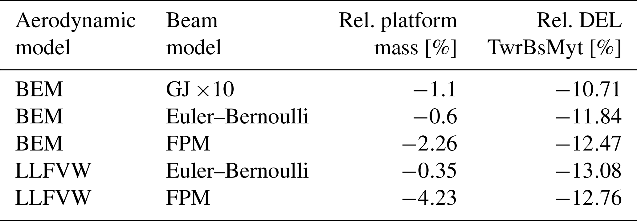
The first optimization problem was formulated to minimize the damage equivalent loads for the tower-base moment by varying the dimensions of the floating substructure together with the pitch controller tuning parameters. The results confirmed that modeling fidelity choices can meaningfully influence key design-driving metrics, such as the rotor thrust and torque and, subsequently, platform pitch, blade pitch actuation and tower-base fore–aft moment. The optimal designs achieved different levels of tower-base bending moment DEL reductions depending on the fidelity combination used, as shown in Table 7. A central mechanism that enabled reduced loads was the decrease in water plane area, which was achieved by reducing the outer column diameter. The maximum platform pitch constraint limited the minimum feasible diameter for each aeroelastic model. Hence, the influence of aeroelastic fidelity on rotor thrust directly affects the resulting platform design. Notably, the llfvw fpm case converged to a design with considerably less platform mass than the bem fpm case and the other configurations.
Table 7Summary of the first optimization problem that aims to reduce tower-base damage equivalent loads.
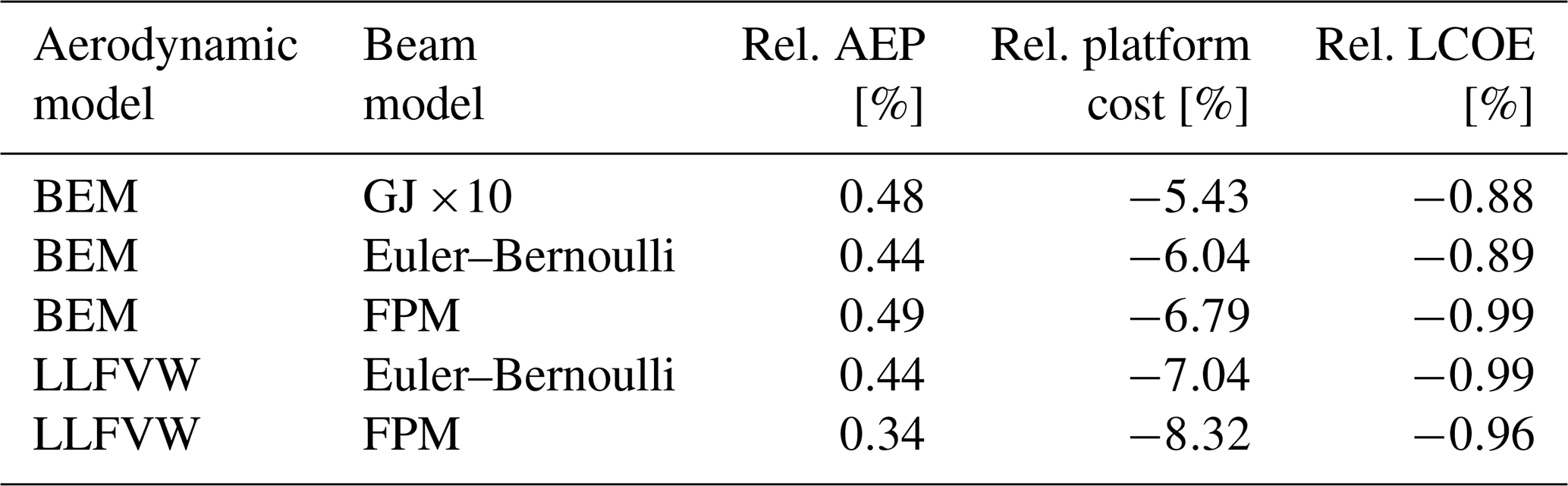
The second optimization was a reformulation of the first problem with levelized cost of energy as the merit figure. Even though this metric proved not to be a perfect basis for comparison across fidelity levels, as differences in baseline AEP values differ significantly between models and AEP affects LCOE significantly more than platform cost, clear trends nevertheless emerged, as shown in Table 8. In this regard, the LLFVW cases achieved the largest platform cost reductions (up to 8.3 %), while the BEM-based cases showed smaller gains. Furthermore, the generator overspeed constraint appears to drive differences in controller parameters between the models. This constraint separates the bem gj10 and Euler–Bernoulli cases from the higher-fidelity models, indicating that aeroelastic fidelity plays an influential role.
Table 8Summary of the second optimization problem that aims to reduce levelized cost of energy.
Higher modeling fidelity comes at a non-negligible computational cost. With the infrastructure used in this study, simulations employing the LLFVW method were approximately 1 order of magnitude more expensive than the BEM method in terms of billed CPU hours and ran at roughly half the speed in wall clock time. The Timoshenko-FPM beam model increased the simulation time only marginally compared to the Euler–Bernoulli formulation. The question of whether an increase in modeling accuracy or a reduction in uncertainty justifies the additional expense has no straightforward answer. However, this work indicates that increasing the level of aeroelastic fidelity affects the optimization outcome. The Timoshenko-FPM and LLFVW methods capture load-alleviating effects like bend–twist and shear–twist coupling for the former and reduced load amplitudes in dynamic conditions for the latter. As a result, reduced standard deviations and min-to-max ranges of various quantities relevant to the design, such as rotational speed or the tower-base fore–aft bending moments, are found. Related metrics, such as the platform pitch, reflect this behavior. Thus, the modeling fidelity directly influences the design space, especially in constrained problems. Consequently, configurations that are unfeasible using lower-fidelity models can be exploited by the optimizer, when the aeroelastic fidelity is increased.
In contrast to other studies, where LLFVW methods could only be applied to a few cases and only when those cases were short and simplified, the efficient numerical implementation in QBlade enables its inclusion in the design phase. Further efficiency gains in numerical algorithms, combined with the rapid global expansion of compute infrastructure, should continue to reduce the relative expense of such models and potentially enable an increased usage of higher fidelity tools in future design processes. Furthermore, multi-fidelity approaches that combine the efficiency of lower-fidelity models with the accuracy of higher-fidelity methods, as demonstrated by Jasa et al. (2022), offer the possibility to include these methods in design processes. Future work will focus on exploring strategies to effectively combine LLFVW and BEM methods.
| AI | Artificial intelligence |
| AEP | Annual energy production |
| BEM | Blade element momentum theory |
| CapEx | Capital expenditure |
| CCD | Control co-design |
| COBYLA | Constrained optimization by linear approximation |
| CPU | Central processing unit |
| EB | Euler–Bernoulli (beam theory) |
| FEA | Finite-element analysis |
| FOWT | Floating offshore wind turbine |
| FPM | Fully populated matrix |
| LCOE | Levelized cost of energy |
| LLFVW | Lifting-line free vortex wake |
| MDAO | Multidisciplinary design analysis and optimization |
| NHR@ZIB | National high-performance computing center at Zuse Institute Berlin |
| NREL | National Renewable Energy Laboratory |
| PSD | Power spectral density |
| RAO | Response amplitude operator |
| RNA | Rotor–nacelle assembly |
| SONATA | Structural Optimization and Aeroelastic Analysis |
| WEIS | Wind Energy with Integrated Servo-control |
| XDSM | eXtended Design Structure Matrix |
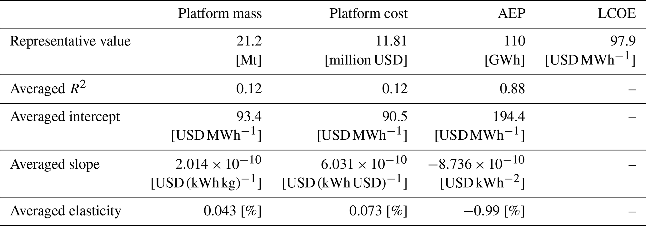
As illustrated in Fig. B1, the linear regression fits demonstrate the relationship between the levelized cost of energy and variations in platform cost, mass and AEP. The analysis indicates that even small changes in energy production have a significant impact on the LCOE metric. At the same time, the effect of platform cost and subsequently mass is very small. In order to quantify the relative importance of AEP and platform mass for the LCOE, the sensitivities regarding LCOE are calculated for the varying measures. These sensitivities can be expressed through elasticity, which can be understood as the percentage change in an output variable (LCOE in this case) with respect to a percentage change in an input variable. For a generic input x and output y, the elasticity can be defined as follows (Hamby, 1994):
To obtain X and Y in Eq. (B1), representative values for platform mass, cost and AEP (for X) and LCOE (for Y) must be selected. For these representative values, the average was calculated across the varying aeroelastic fidelity levels from the initial iteration. The elasticities and further details concerning the linear regression are presented in Table B1.
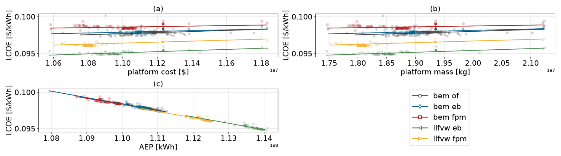
Figure B1Linear regression fits showing the relationship between LCOE and platform cost (a), platform mass (b) and AEP (c).
Table B1Linear regression coefficients, fit statistics and elasticities of LCOE with respect to platform mass, platform cost and AEP, averaged across the five aeroelastic fidelity optimizations.
For optimization, the QBtoWEIS interface was employed, which couples QBlade to the WEIS framework. The exact version of QBtoWEIS (v1.1.0) used in this study is archived at https://doi.org/10.5281/zenodo.16964579 (Behrens de Luna, 2025), while the maintained repository is available at https://github.com/rbehrensdeluna/QBtoWEIS.git (last access: 15 December 2025). All simulations were carried out in the QBladeEE simulation environment (Enterprise Edition; for further information, see https://qblade.org, last access: 15 December 2025). A free community edition of QBlade, capable of running such optimizations, can be downloaded at https://qblade.org/downloads/ (last access: 15 December 2025).
The conceptualization, methodology, simulations, post-processing, data analysis and paper preparation were carried out by RBdL. FP supported the interpretation of results and contributed to editing the paper. DM contributed through the development of the QBlade code, specifically enhancing compatibility with HPC execution and improving computational efficiency. COP provided supervision and feedback during the preparation of the work. All authors reviewed the paper.
The contact author has declared that none of the authors has any competing interests.
Views and opinions expressed are however those of the author(s) only and do not necessarily reflect those of the European Union or the European Climate, Infrastructure and Environment Executive Agency (CINEA), which cannot be held responsible for them.
Publisher's note: Copernicus Publications remains neutral with regard to jurisdictional claims made in the text, published maps, institutional affiliations, or any other geographical representation in this paper. While Copernicus Publications makes every effort to include appropriate place names, the final responsibility lies with the authors. Views expressed in the text are those of the authors and do not necessarily reflect the views of the publisher.
This work has received the support of the FLOATFARM Project, funded by the European Union's Horizon Europe research and innovation program under grant agreement no. 101136091. The authors gratefully acknowledge the computing time made available to them on the high-performance computer Lise at the NHR center NHR@ZIB. This center is jointly supported by the Federal Ministry of Education and Research and the state governments participating in the NHR (http://www.nhr-verein.de, last access: 15 December 2025). During the preparation of this work, artificial intelligence (AI) through ChatGPT (GPT-5, OpenAI) and DeepL Write (DeepL SE) was employed solely for grammatical correction, stylistic refinement and improvements in readability. At no stage were these tools used to generate, modify or verify any scientific results or methodological approaches. All substantive scientific ideas and proposed methodologies were developed independently by the authors without reliance on AI systems.
This research has been supported by the European Climate, Infrastructure and Environment Executive Agency (grant no. 101136091).
The publication of this article was funded by the Open Access Publication Fund of TU Berlin.
This paper was edited by Maurizio Collu and reviewed by two anonymous referees.
Abbas, N. J., Zalkind, D. S., Pao, L., and Wright, A.: A reference open-source controller for fixed and floating offshore wind turbines, Wind Energ. Sci., 7, 53–73, https://doi.org/10.5194/wes-7-53-2022, 2022. a, b
Abbas, N. J., Jasa, J., Zalkind, D. S., Wright, A., and Pao, L.: Control Co-Design of a Floating Offshore Wind Turbine, Applied Energy, 353, 122036, https://doi.org/10.1016/j.apenergy.2023.122036, 2024. a, b, c
Bayat, S., Lee, Y. H., and Allison, J. T.: Nested control co-design of a spar buoy horizontal-axis floating offshore wind turbine, Ocean Eng., 328, 121037, https://doi.org/10.1016/j.oceaneng.2025.121037, 2025. a
Behrens de Luna, R.: QBtoWEIS, Zenodo [code], https://doi.org/10.5281/zenodo.16964579, 2025. a, b
Behrens de Luna, R., Marten, D., Barlas, T., Horcas, S. G., Ramos-García, N., Li, A., and Paschereit, C. O.: Comparison of different fidelity aerodynamic solvers on the IEA 10 MW turbine including novel tip extension geometries, Journal of Physics: Conference Series, 2265, 032002, https://doi.org/10.1088/1742-6596/2265/3/032002, 2022. a
Behrens de Luna, R., Perez-Becker, S., Saverin, J., Marten, D., Papi, F., Ducasse, M.-L., Bonnefoy, F., Bianchini, A., and Paschereit, C.-O.: Quantifying the impact of modeling fidelity on different substructure concepts for floating offshore wind turbines – Part 1: Validation of the hydrodynamic module QBlade-Ocean, Wind Energ. Sci., 9, 623–649, https://doi.org/10.5194/wes-9-623-2024, 2024. a, b, c
Bergua, R., Robertson, A., Jonkman, J., Branlard, E., Fontanella, A., Belloli, M., Schito, P., Zasso, A., Persico, G., Sanvito, A., Amet, E., Brun, C., Campaña-Alonso, G., Martín-San-Román, R., Cai, R., Cai, J., Qian, Q., Maoshi, W., Beardsell, A., Pirrung, G., Ramos-García, N., Shi, W., Fu, J., Corniglion, R., Lovera, A., Galván, J., Nygaard, T. A., dos Santos, C. R., Gilbert, P., Joulin, P.-A., Blondel, F., Frickel, E., Chen, P., Hu, Z., Boisard, R., Yilmazlar, K., Croce, A., Harnois, V., Zhang, L., Li, Y., Aristondo, A., Mendikoa Alonso, I., Mancini, S., Boorsma, K., Savenije, F., Marten, D., Soto-Valle, R., Schulz, C. W., Netzband, S., Bianchini, A., Papi, F., Cioni, S., Trubat, P., Alarcon, D., Molins, C., Cormier, M., Brüker, K., Lutz, T., Xiao, Q., Deng, Z., Haudin, F., and Goveas, A.: OC6 project Phase III: validation of the aerodynamic loading on a wind turbine rotor undergoing large motion caused by a floating support structure, Wind Energ. Sci., 8, 465–485, https://doi.org/10.5194/wes-8-465-2023, 2023. a, b
Boorsma, K. and Schepers, J. G.: New MEXICO Experiment, Preliminary Overview, ECN publication ECN-E–14-048, ECN Wind Energy, https://publications.ecn.nl/ECN-E--14-048 (last access: 15 December 2025), 2014. a
Boorsma, K., Hartvelt, M., and Orsi, L.: Application of the lifting line vortex wake method to dynamic load case simulations, Journal of Physics: Conference Series, 753, 022030, https://doi.org/10.1088/1742-6596/753/2/022030, 2016. a
Boorsma, K., Wenz, F., Lindenburg, K., Aman, M., and Kloosterman, M.: Validation and accommodation of vortex wake codes for wind turbine design load calculations, Wind Energ. Sci., 5, 699–719, https://doi.org/10.5194/wes-5-699-2020, 2020. a, b
Bortolotti, P., Bay, C., Barter, G., Gaertner, E., Dykes, K., McWilliam, M., Friis-Moller, M., Molgaard Pedersen, M., and Zahle, F.: System Modeling Frameworks for Wind Turbines and Plants: Review and Requirements Specifications, Tech. Rep. NREL/TP-5000-82621, National Renewable Energy Laboratory, Golden, CO, https://doi.org/10.2172/1868328, 2022. a
Bortolotti, P., Chetan, M., Branlard, E., Jonkman, J., Platt, A., Slaughter, D., and Rinker, J.: Wind Turbine Aeroelastic Stability in OpenFAST, Journal of Physics: Conference Series, 2767, 022018, https://doi.org/10.1088/1742-6596/2767/2/022018, 2024. a
Branlard, E., Jonkman, B., Pirrung, G. R., Dixon, K., and Jonkman, J.: Dynamic inflow and unsteady aerodynamics models for modal and stability analyses in OpenFAST, Journal of Physics: Conference Series, 2265, 032044, https://doi.org/10.1088/1742-6596/2265/3/032044, 2022. a
Buhl Jr., M.: New Empirical Relationship between Thrust Coefficient and Induction Factor for the Turbulent Windmill State, Technical Report NREL/TP-500-36834, National Renewable Energy Laboratory, Golden, CO, USA, https://doi.org/10.2172/15016819, 2005. a
Burton, T., Sharpe, D., Jenkins, N., and Bossanyi, E.: Wind Energy Handbook, 1st edn., John Wiley & Sons, ISBNs 0-471-48997-2, 2001. a
Collier, W., Ors, D., Barlas, T., Zahle, F., Bortolotti, P., Marten, D., Jensen, C. S. L., Branlard, E., Zalkind, D., and Lønbæk, K.: Aeroelastic code comparison using the IEA 22 MW reference turbine, Journal of Physics: Conference Series, 2767, 052042, https://doi.org/10.1088/1742-6596/2767/5/052042, 2024. a
Feil, R., Pflumm, T., Bortolotti, P., and Morandini, M.: A cross-sectional aeroelastic analysis and structural optimization tool for slender composite structures, Composite Structures, 253, 112755, https://doi.org/10.1016/j.compstruct.2020.112755, 2020. a
FLOATFARM: Project Website, https://floatfarm-project.eu/, last access: 11 September 2025. a, b
Garcia-Sanz, M.: Control Co-Design: An engineering game changer, Advanced Control for Applications: Engineering and Industrial Systems, 1, e18, https://doi.org/10.1002/adc2.18, 2019. a, b, c
Ghigo, A., Cottura, L., Caradonna, R., Bracco, G., and Mattiazzo, G.: Platform Optimization and Cost Analysis in a Floating Offshore Wind Farm, Journal of Marine Science and Engineering, 8, https://doi.org/10.3390/jmse8110835, 2020. a
Gray, J. S., Hwang, J. T., Martins, J. R. R. A., Moore, K. T., and Naylor, B. A.: OpenMDAO: An open-source framework for multidisciplinary design, analysis, and optimization, Structural and Multidisciplinary Optimization, 59, 1075–1104, https://doi.org/10.1007/s00158-019-02211-z, 2019. a
Guo, F., Gao, Z., and Schlipf, D.: TorqTwin – An open-source reference multibody modeling framework for wind turbine structural dynamics, Renewable Energy, 235, 121268, https://doi.org/10.1016/j.renene.2024.121268, 2024. a, b
Hamby, D. M.: A review of techniques for parameter sensitivity analysis of environmental models, Environ. Monit. Assess., 32, 135–154, https://doi.org/10.1007/BF00547132, 1994. a
Hansen, M. O. L.: Aerodynamics of Wind Turbines, Earthscan, London, 2nd edn., ISBN 978-1-84407-438-9, 2008. a
Harris, C. R., Millman, K. J., van der Walt, S. J., Gommers, R., Virtanen, P., Cournapeau, D., Wieser, E., Taylor, J., Berg, S., Smith, N. J., Kern, R., Picus, M., Hoyer, S., van Kerkwijk, M. H., Brett, M., Haldane, A., del Río, J. F., Wiebe, M., Peterson, P., Gérard-Marchant, P., Sheppard, K., Reddy, T., Weckesser, W., Abbasi, H., Gohlke, C., and Oliphant, T. E.: Array programming with NumPy, Nature, 585, 357–362, https://doi.org/10.1038/s41586-020-2649-2, 2020. a
Hauptmann, S., Bülk, M., Schön, L., Erbslöh, S., Boorsma, K., Grasso, F., Kühn, M., and Cheng, P. W.: Comparison of the lifting-line free vortex wake method and the blade-element-momentum theory regarding the simulated loads of multi-MW wind turbines, Journal of Physics: Conference Series, 555, 012050, https://doi.org/10.1088/1742-6596/555/1/012050, 2014. a
Hodges, D.: Nonlinear Composite Beam Theory, https://doi.org/10.2514/4.866821, 2006. a
International Electrotechnical Commission: Wind turbines – Part 1: Design requirements, standard No. IEC 61400-1, 4th ed. Geneva, Switzerland, ISBN 9782832279724, 2019. a
Jasa, J., Bortolotti, P., Zalkind, D., and Barter, G.: Effectively using multifidelity optimization for wind turbine design, Wind Energ. Sci., 7, 991–1006, https://doi.org/10.5194/wes-7-991-2022, 2022. a
Johnson, S. G.: The NLopt nonlinear-optimization package, GitHub [code], https://github.com/stevengj/nlopt (last access: 15 December 2025), 2007. a
Jonkman, J.: Definition of the Floating System for Phase IV of OC3, NREL technical report, https://doi.org/10.2172/979456, 2010. a
Jonkman, J. M. and Buhl Jr., M. L.: FAST User's Guide – Updated August 2005, Technical Report NREL/TP-500-38230, National Renewable Energy Laboratory, Golden, CO, USA, https://doi.org/10.2172/15020796, 2005. a
Larsen, T. J. and Hanson, T. D.: A method to avoid negative damped low frequent tower vibrations for a floating, pitch controlled wind turbine, Journal of Physics: Conference Series, 75, 012073, https://doi.org/10.1088/1742-6596/75/1/012073, 2007. a
Madsen, H. A., Larsen, T. J., Pirrung, G. R., Li, A., and Zahle, F.: Implementation of the blade element momentum model on a polar grid and its aeroelastic load impact, Wind Energ. Sci., 5, 1–27, https://doi.org/10.5194/wes-5-1-2020, 2020. a, b
Mancini, S., Boorsma, K., Schepers, G., and Savenije, F.: A comparison of dynamic inflow models for the blade element momentum method, Wind Energ. Sci., 8, 193–210, https://doi.org/10.5194/wes-8-193-2023, 2023. a
Marten, D.: QBlade: A Modern Tool for the Aeroelastic Simulation of Wind Turbines, PhD thesis, TUB, https://doi.org/10.14279/depositonce-10646, 2020. a, b, c, d, e
Martins, J. R. R. A. and Ning, A.: Engineering Design Optimization, Cambridge University Press, Cambridge, UK, https://doi.org/10.1017/9781108980647, 2022. a
Morandini, M., Chierichetti, M., and Mantegazza, P.: Characteristic behavior of prismatic anisotropic beam via generalized eigenvectors, International Journal of Solids and Structures, 47, 1327–1337, https://doi.org/10.1016/j.ijsolstr.2010.01.017, 2010. a
NREL: BeamDyn Module, GitHub [code], https://github.com/OpenFAST/openfast/tree/main/modules/beamdyn, last access: 11 November 2025a. a
NREL: ElastoDyn Users Guide and Theory Manual, https://openfast.readthedocs.io/en/dev/source/user/elastodyn/index.html, last access: 11 November 2025b. a, b
NREL: OpenFAST, GitHub [code], https://github.com/OpenFAST/openfast, last access: 11 November 2025c. a
NREL: ROSC O. Version 2.9.7, GitHub [code], https://github.com/NREL/ROSCO, last access: 11 November 2025d. a
NREL: SONATA, GitHub [code], https://github.com/WISDEM/SONATA/tree/master, last access: 11 November 2025e. a
NREL: WEIS, GitHub [code], https://github.com/WISDEM/WEIS, last access: 11 November 2025f. a
NREL: WISDEM, GitHub [code], https://github.com/WISDEM/WISDEM, last access: 11 November 2025g. a
NREL: pCrunch, GitHub [code], https://github.com/NREL/pCrunch, last access: 11 November 2025h. a
NREL: pyHAMS, GitHub [code], https://github.com/WISDEM/pyHAMS, last access: 11 November 2025i. a
Ojo, A., Collu, M., and Coraddu, A.: Multidisciplinary design analysis and optimization of floating offshore wind turbine substructures: A review, Ocean Eng., 266, 112727, https://doi.org/10.1016/j.oceaneng.2022.112727, 2022. a
Papi, F., Perignon, Y., and Bianchini, A.: Derivation of Met–Ocean Conditions for the Simulation of Floating Wind Turbines: A European Case Study, Journal of Physics: Conference Series, 2385, 012117, https://doi.org/10.1088/1742-6596/2385/1/012117, 2022. a
Papi, F., Jonkman, J., Robertson, A., and Bianchini, A.: Going beyond BEM with BEM: an insight into dynamic inflow effects on floating wind turbines, Wind Energ. Sci., 9, 1069–1088, https://doi.org/10.5194/wes-9-1069-2024, 2024a. a
Papi, F., Troise, G., Behrens de Luna, R., Saverin, J., Perez-Becker, S., Marten, D., Ducasse, M.-L., and Bianchini, A.: Quantifying the impact of modeling fidelity on different substructure concepts – Part 2: Code-to-code comparison in realistic environmental conditions, Wind Energ. Sci., 9, 981–1004, https://doi.org/10.5194/wes-9-981-2024, 2024b. a, b, c
Perez-Becker, S., Papi, F., Saverin, J., Marten, D., Bianchini, A., and Paschereit, C. O.: Is the Blade Element Momentum theory overestimating wind turbine loads? – An aeroelastic comparison between OpenFAST's AeroDyn and QBlade's Lifting-Line Free Vortex Wake method, Wind Energ. Sci., 5, 721–743, https://doi.org/10.5194/wes-5-721-2020, 2020. a, b, c, d
Powell, M. J. D.: A Direct Search Optimization Method That Models the Objective and Constraint Functions by Linear Interpolation, https://api.semanticscholar.org/CorpusID:118045691 (last access: 15 December 2025), 1994. a
QBlade: https://docs.qblade.org/, last access: 11 November 2025. a
Ramachandran, G. K. V., Robertson, A., Jonkman, J. M., and Masciola, M. D.: Investigation of Response Amplitude Operators for Floating Offshore Wind Turbines, in: Proceedings of the 23rd International Ocean, Offshore and Polar Engineering Conference (ISOPE 2013), NREL/CP-5000-58098, Anchorage, Alaska, USA, conference Paper NREL/CP-5000-58098; to be presented 30 June–5 July 2013, https://docs.nrel.gov/docs/fy13osti/58098.pdf (last access: 15 December 2025), 2013. a
Ramos-García, N., Kontos, S., Pegalajar-Jurado, A., González Horcas, S., and Bredmose, H.: Investigation of the floating IEA Wind 15 MW RWT using vortex methods Part I: Flow regimes and wake recovery, Wind Energy, 25, 468–504, https://doi.org/10.1002/we.2682, 2022. a
Schulz, C. W., Bergua, R., Branlard, E., Netzband, S., Jonkman, J., and Robertson, A.: Unsteady aerodynamics of large-scale floating offshore wind turbines in surge motion, Renewable Energy, https://doi.org/10.1016/j.renene.2025.124977, 2025. a, b, c, d, e, f
Nielsen, F. G., Hanson, T. D., and Skaare, B.: Integrated Dynamic Analysis of Floating Offshore Wind Turbines, International Conference on Offshore Mechanics and Arctic Engineering, https://doi.org/10.1115/OMAE2006-92291, 2006. a
Snel, H. and Schepers, J. G.: Joint Investigation of Dynamic Inflow Effects and Implementation of an Engineering Method, Technical Report ECN-C-94-107, Energy Research Centre of the Netherlands (ECN), Petten, the Netherlands, https://www.osti.gov/etdeweb/biblio/53347 (last access: 15 December 2025), 1995. a
Stäblein, A. R.: Analysis and Design of Bend-Twist Coupled Wind Turbine Blades, Springer International Publishing, Cham, 67–80, https://doi.org/10.1007/978-3-319-39095-6_5, 2016. a, b, c
Tasora, A., Serban, R., Mazhar, H., Pazouki, A., Melanz, D., Fleischmann, J., Taylor, M., Sugiyama, H., and Negrut, D.: Chrono: An Open Source Multi-physics Dynamics Engine, in: Lecture Notes in Computer Science, Springer International Publishing, 19–49, https://doi.org/10.1007/978-3-319-40361-8_2, 2016. a
TUM: SONATA, GitLab [code], https://gitlab.lrz.de/HTMWTUM/SONATA, last access: 11 November 2025. a
van der Veen, G., Couchman, I., and Bowyer, R.: Control of floating wind turbines, 3148–3153, https://doi.org/10.1109/ACC.2012.6315120, 2012. a
van Garrel, A.: Development of a Wind Turbine Aerodynamics Simulation Module, Tech. rep., https://doi.org/10.13140/RG.2.1.2773.8000, 2003. a
Veers, P., Bottasso, C., Manuel, L., Naughton, J., Pao, L., Paquette, J., Robertson, A., Robinson, M., Ananthan, S., Barlas, A., Bianchini, A., Bredmose, H., Horcas, S. G., Keller, J., Madsen, H. A., Manwell, J., Moriarty, P., Nolet, S., and Rinker, J.: Grand Challenges in the Design, Manufacture, and Operation of Future Wind Turbine Systems, Wind Energ. Sci., 8, 1071–1131, https://doi.org/10.5194/wes-8-1071-2023, 2023. a, b
WEIS Documentation: https://weis.readthedocs.io/en/latest/index.html, last access: 11 November 2025. a
Yu, W., Zhou, S. T., Lemmer, F., and Cheng, P. W.: Control co-design optimization of floating offshore wind turbines with tuned liquid multi-column dampers, Wind Energ. Sci., 9, 1053–1068, https://doi.org/10.5194/wes-9-1053-2024, 2024. a
Zahle, F., Barlas, A., Lønbæk, K., Bortolotti, P., Zalkind, D., Wang, L., Labuschagne, C., Sethuraman, L., and Barter, G.: Definition of the IEA Wind 22-Megawatt Offshore Reference Wind Turbine, Technical University of Denmark, dTU Wind Energy Report E-0243 IEA Wind TCP Task 55, https://doi.org/10.11581/DTU.00000317, 2024a. a, b, c, d, e, f, g
Zahle, F., Barlas, T., Lønbæk, K., Bortolotti, P., Zalkind, D., Wang, L., Labuschagne, C., Sethuraman, L., Barter, G., and Marten, D.: IEAWindTask37/IEA-22-280-RWT: v1.0.1, Zenodo [code], https://doi.org/10.5281/zenodo.10944127, 2024b. a
Zalkind, D. and Bortolotti, P.: Control Co-Design Studies for a 22 MW Semisubmersible Floating Wind Turbine Platform, Journal of Physics: Conference Series, 2767, 082020, https://doi.org/10.1088/1742-6596/2767/8/082020, 2024. a, b, c, d
Zalkind, D., Abbas, N. J., Jasa, J., Wright, A., and Fleming, P.: Floating wind turbine control optimization, Journal of Physics: Conference Series, 2265, 042021, https://doi.org/10.1088/1742-6596/2265/4/042021, 2022. a, b, c, d
Zhao, X., Jiang, W., Liang, Z., and Zhao, Y.: Passive load reduction performance of bend-twist coupling in large flexible wind turbine blades, Composite Structures, 371, 119421, https://doi.org/10.1016/j.compstruct.2025.119421, 2025. a
These bins include 5, 7, 9, 11, 13, 15, 17, 20, 23 and 25 m s−1.
This load channel is defined by default in WEIS as the resulting magnitude of the tower-base bending moments in fore–aft directions, side–side directions and torsion, computed using the Frobenius norm (based on NumPy's numpy.linalg.norm() function; Harris et al., 2020). The damage equivalent loads are subsequently calculated using the standard rainflow-counting procedure implemented in pCrunch on this resulting time series. The moment in the fore–aft direction is the strongest contributor to the metric.
The reduced frequency is a dimensionless number defined as , with f denoting the nacelle velocity frequency in the fore–aft direction, D the diameter and v0 the wind velocity parallel to the rotor axis (Schulz et al., 2025).
- Abstract
- Introduction
- Optimization framework and methods
- Optimization problem, modeling considerations and computation
- Results and analysis
- Conclusion and outlook
- Appendix A: Nomenclature
- Appendix B
- Code and data availability
- Author contributions
- Competing interests
- Disclaimer
- Acknowledgements
- Financial support
- Review statement
- References