the Creative Commons Attribution 4.0 License.
the Creative Commons Attribution 4.0 License.
 | 04 Feb 2025
Effect of blade inclination angle for straight-bladed vertical-axis wind turbines
Laurence Morgan
Abbas Kazemi Amiri
William Leithead
James Carroll
Vertical-axis wind turbines (VAWTs) have received renewed research interest in the offshore environment due to a number of design synergies that have the potential to decrease the cost of energy for offshore wind. Many studies have been completed on the rotor design for straight-bladed rotors (H-rotors); however, there is sparse information on the effect of blade inclination angle on VAWT aerodynamic performance and the optimal blade design of VAWTs with inclined blades (V-rotors) for maximum power capture.
This paper presents a systematic study into the effect of blade inclination angle and chord distribution on VAWT performance for different aspect ratios using a 3D implementation of the 2D actuator cylinder model which has been previously validated against higher-fidelity methods. A systematic approach based on a grid search is used to allow the wider design space to be studied and trends identified.
In the case of fixed-chord-length blades, it is found that significant power gains are available through blade inclination, between 12 % and 71 % depending on blade length. This is driven by the increase in rotor swept area. Further investigation indicates that despite this, under maximum blade stress limitations the most economical solution for fixed-chord-length blades is H-rotors. Optimal chord distributions, which maximise the rotor power coefficient, are then obtained, and a natural blade taper is observed. For rotors with optimal chord distributions, similar power gains are observed through blade inclination, again between 12 % and 71 % depending on blade length. However, rotor configurations with the largest power gains are found to have significantly increased blade mass. For a given power rating, whilst satisfying limitations on maximum blade root bending stress, it is found that blade volume, a proxy for the blade mass, can be reduced between 16 % and 42 % dependent on blade length, and rotor torque can be reduced between 4 % and 9 %. This indicates the potential of V-rotors to reduce the cost of energy compared to H-rotors in traditional VAWT designs. Additionally, inclined blades are shown to increase the operational tip-speed ratio, demonstrating their applicability to turbines using secondary rotors, such as the X-rotor, where high tip-speed ratios are required for efficient power conversion between primary and secondary rotors.
- Article
(2465 KB) - Full-text XML
- BibTeX
- EndNote


1.1 background
Renewable energies are key to combating the ongoing climate crisis, and offshore wind energy is an integral pillar of this response (IRENA, 2022). It has been estimated that a 3-fold increase in the rate of deployment of wind energy is required by 2030 to meet global climate goals (Lee and Zhao, 2021), and decreasing the cost of energy for offshore wind can significantly increase the rate of offshore wind deployment. In this context, vertical-axis wind turbines (VAWTs) have been identified as a technology that has the potential to significantly reduce the cost of offshore wind energy due to a number of design synergies (Borg et al., 2012; Sutherland et al., 2012). Further to this, recent work has demonstrated that VAWT wakes can recover significantly faster than those of traditional horizontal-axis wind turbines (HAWTs), facilitating increased wind farm density (Huang, 2023) and further reductions in the cost of energy. This has led to significant academic and commercial interest in a variety of design concepts (Hand and Cashman, 2020).
VAWTs have many potential configurations, with any 2D shape possessing vertical symmetry representing a possible rotor configuration. For large offshore structures, practical design considerations have led to a convergence on two key designs: Darrieus VAWTs, with curved blades attached at both the blade root and tip, and straight-bladed VAWTs, typically configured with blades orientated parallel to the axis of rotation in an “H” configuration. Straight-bladed designs with inclined blades have also been proposed (Ljungström et al., 1974; Musgrove, 1977; Sharpe and Taylor, 1983; Shires, 2013a; Leithead et al., 2019); these rotors will henceforth be referred to as V-rotors.
1.2 Historical development of V-rotors
The use of V-rotors was first introduced by Ljungström et al. (1974), initially referred to as “Y” rotors. It was noted in this work that straight-bladed VAWTs facilitated cyclic pitching more easily than the Darrieus type. This rotor concept was also briefly described by Park (1976). A variable geometry H-rotor with inclinable blades was later proposed by Musgrove (1977); this used a reefing system to incline the blades as a means of reducing power capture at high wind speeds. Wind tunnel tests on a scale model conducted by Willmer (1980) demonstrated that the power coefficient decreased significantly as the blade inclination angle was increased from 0 to 60°. Figure 1a shows the “Musgrove 250” turbine with blades in the “reefed” position.
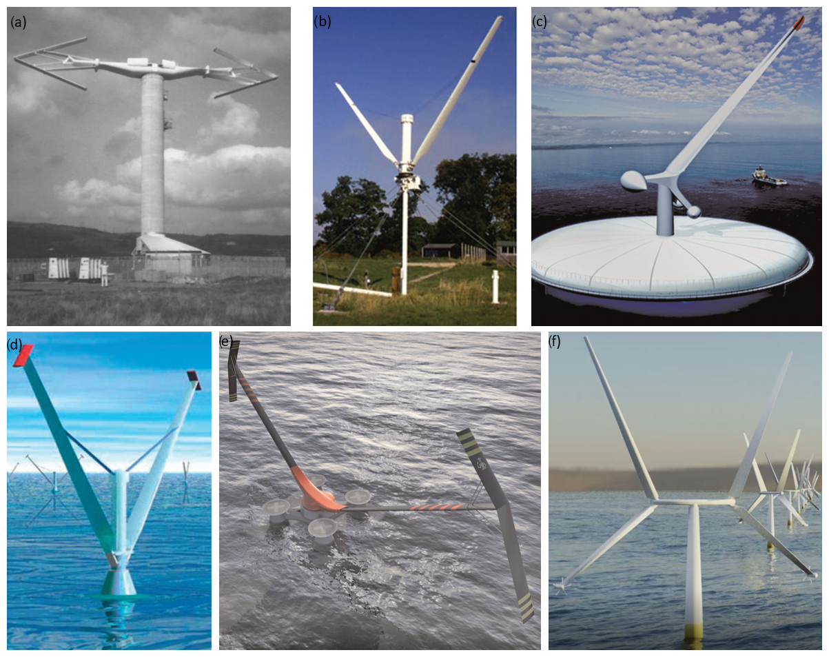
Figure 1(a) Musgrove 250 turbine (Price, 2006), (b) 5 kW V-rotor tested by Sharpe and Derek Taylor (The Open University, 2015), (c) single-bladed V-rotor concept (Shires, 2013a), (d) Taylor V-turbine (The Open University, 2015), (e) the aerogenerator concept (Shires, 2013a), and (f) the X-rotor wind turbine concept.
David Sharpe further developed Ljungström's rotor concept from 1983 onwards (Sharpe and Taylor, 1983). These designs did not utilise a cross-arm with the blades attached directly to the rotor hub. Listed benefits of the design included the reduction in capital costs due to the short rotor tower and the lack of cross-arm, the ease of manufacturing of straight (untwisted) blades, the potential for control with either variable geometry or variable pitch, and the increased portion of the rotor swept area sampling higher wind speeds at high altitudes. An initial study determined the power coefficient for inclination angles of 35, 45, and 55° for a blade aspect ratio of 11.9, finding the maximum power coefficient occurring with an inclination angle of 55°. Additionally, increasing blade aspect ratio was found to increase the peak power coefficient for an inclination angle of 45° (Sharpe and Taylor, 1983). The aerodynamic simulation work was completed using a blade element momentum (BEM)-based double-multiple streamtube (DMS) theory approach described in Sharpe (1984). Further work was completed, validating the aerodynamic simulation work and demonstrating how the rotor could be controlled using a tip-pitch system in Robotham et al. (1985), and a 5 kW system was field-tested in 1987 (Sharpe et al., 1987); this system is shown in Fig. 1b. Following these tests, a single-bladed design utilising a counterbalancing weight was proposed (Shires, 2013a); this design is shown in Fig. 1c. Following this period, the development of V-rotor concepts was predominantly undertaken by private engineering companies. Altechnica continued to work on the concept through the “Taylor V-turbine” as shown in Fig. 1d.
The next significant academic work on V-rotors was undertaken in the NOVA project within the design of the Aerogenerator X as shown in Fig. 1e (Shires, 2013a). This work was conducted as a partnership of a number of British academic institutions in conjunction with Wind Power Ltd. A 10 MW V-rotor was designed, and the rotor blades were augmented with sails aimed at counteracting the aerodynamic overturning moments inherent in V-rotor designs; the rotor design work is presented in Shires (2013a). A gradient-based optimisation approach was coupled to a DMS-based aerodynamic solver (Shires, 2013b) and was used to find a rotor geometry that minimised the rotor volume (used as a proxy for the rotor cost) under a number of design constraints, including ensuring a rated power of 10 MW at 13 m s−1 with rated rotor speed of 4 rpm, a limitation on the maximum overturning moment, and a constraint on the maximum length of unsupported sails and struts. The completed optimisation was found to decrease the rotor volume by 3 % whilst preserving the aerodynamic power and decreasing the overturning moment by 11 %. For some of the optimisations presented, the inclination of the rotor blades was a free variable; however, the optimisation procedure did not significantly alter the initial inclination angle of 59°.
Following the completion of the NOVA project, the X-rotor wind turbine concept began development at the University of Strathclyde (Leithead et al., 2019), and further research is underway in the form on an EU H2020 project (Cordis, 2023). The turbine consists of an X-shaped primary rotor, made up of an upper and lower V, which utilises secondary rotors attached to the tips of the lower V for power take-off. The use of inclined rotor blades is critical in the X-rotor concept as a means of increasing the primary rotor tip-speed ratio, which is key to ensuring efficient power conversion between the primary and secondary rotors (Morgan et al., 2024). A rendering of the turbine concept is shown in Fig. 1e. The primary rotor blades are attached to a central cross-arm with a radius of 25 m and extend to a tip radius of 75 m, with inclination angles of 30 and 130°, respectively. The lower blades reduce the overturning moment in a similar manner to the sails of the aerogenerator concept and provide an attachment location for the secondary rotors. The aerodynamic and structural design of the rotor is presented in Leithead et al. (2019); however, the aerodynamic design process of the primary rotor was not presented. A DMS model was developed and validated against higher-fidelity lifting-line free-vortex wake simulations to simulate the X-rotor turbine in Morgan and Leithead (2022), and a comparison of multiple aerodynamic codes simulating the primary rotor is presented in Giri Ajay et al. (2023).
Absent from the current work published on V-rotors, as represented in this literature review, is a systematic study of the effect of key rotor design parameters, particularly the blade inclination angle, on aerodynamic performance. This hinders the design of V-rotors at the conceptual stage. There are some sparse data on the effect on rotor inclination angle for specific blade and rotor designs at the lab scale (Willmer, 1980; Sharpe and Taylor, 1983); however, these show conflicting trends. Additionally, whilst the effect of solidity and aspect ratio have been well studied for H-rotors, thus far these parameters have not been significantly investigated for V-rotors. In the case of rotor solidity, this may be critically important as V-rotor blade sections operate at different tip-speed ratios due to the change in radius. This indicates that blades with a variable chord distribution are likely to increase aerodynamic efficiency.
Additionally, the current literature on V-rotors does not explicitly describe the effect of rotor geometry on power capture. Results are typically presented with respect to the rotor power coefficient CP; however, it is unclear whether the normalisation area is defined with the initial turbine area or the rotor with inclined blades. A key benefit of the V-rotor concept is the increase in swept area achievable by inclining a blade of fixed length; this must be explicitly accounted for when presenting results.
1.3 Importance of blade inclination angle
A thorough review of VAWT design presented in Hand et al. (2021), alongside the review of V-rotor development in the previous section, demonstrates the lack of systematic investigation into the effect of blade inclination angle on straight-bladed VAWT performance. Investigations into the effect of blade inclination angle will expand the study of straight-bladed VAWTs from the design subspace of H-rotors into an expanded design space considering V rotors, and it is therefore key in fully realising the potential of straight-bladed VAWT rotors.
To understand the effect of blade inclination angle on power capture, one must consider the general equation describing the power captured by a wind turbine:
where ρ represents air density, A the rotor area, CP the power coefficient, and U0 the incident wind speed. Increasing the blade inclination angle affects both the swept area and the rotor power coefficient. Initially, increasing the blade inclination angle increases the swept area of the rotor, increasing the power available to the rotor. Alongside this, increasing the blade inclination angle is expected to decrease the power coefficient, as the blade sections are at different radii and are therefore operating at different (and therefore inherently sub-optimal) tip-speed ratios. The effect of inclining a straight-bladed VAWT rotor blade must therefore be understood through both the increase in swept area and the decrease in power coefficient. The perceived benefit of V-rotors is the ability of rotors to sweep a larger area using the same amount of rotor material. If the increase in swept area outweighs the decrease in power coefficient, blade inclination will increase the power output of a rotor. Since the effect of blade inclination on both swept area and power coefficient is also dependent on the blade length, rotors of different aspect ratios must be studied. Additionally, alongside the effect on power capture, the change in blade and rotor loads must also be considered.
1.4 Research contribution
This paper presents the results from a systematic numerical study of straight-bladed VAWT configurations. The study is performed with the goal of understanding the effect of blade inclination angle and blade chord length on the aerodynamic performance of rotors with different aspect ratios, as well as investigating optimal blade design for V-rotors. Firstly, fixed-chord-length blades are considered, and the effects of chord length, inclination angle, and rotor aspect ratio are investigated in terms of power production, thrust loading, and optimal tip-speed ratio. Following this, the data from these simulations are used to define blade plan-form designs that are optimised for maximum power capture. The effects of blade inclination angle and design tip-speed ratio on the optimal blade plan form are then discussed. Finally, the aerodynamic performance of these optimal blades is presented, and the opportunity for reductions in the cost of energy is discussed.
A systematic approach based on a grid search rather than an optimisation tool is used as it allows the wider design space to be studied and understood, allowing for broad trends to be identified and engineering judgements to be applied without the formulation of specific cost functions. The investigation will use a single aerofoil section (NACA0018) and will not consider twisted or pitched rotor blades, as the introduction of these design variables would considerably increase the design space; these limitations are discussed in Sect. 2.3.
In conclusion this paper provides
-
a systematic study of the effect of blade inclination angle and chord length on the aerodynamic performance of straight-bladed VAWTs with different aspect ratios
-
a study of the optimal chord distribution of inclined VAWT blades of different aspect ratios
-
an evaluation of the potential for inclined blades to lower blade volume and rotor torque.
1.5 Paper structure
Section 2 describes the methodology used for numerical simulation, rotor geometry generation, and blade geometry generation. Section 3 presents the key results from the numerical study, including the rotor performance parameters and optimum blade design, and Sect. 4 discusses these results. Finally Sect. 5 provides an overview of the key research outcomes and discusses avenues where work could be continued.
2.1 Numerical simulation
The numerical simulation of VAWTs is considerably more complex than that of HAWTs, both at the rotor scale and at the blade element scale. At the rotor scale, the flow interacts with the rotor surface twice, initially in the upwind and then in the downwind sweep. At the blade element scale, large cyclic variations in the angle of attack were experienced along the blade, which further complicated numerical simulation. This work utilises a 2D actuator cylinder (2DAC) approach for the numerical simulation of the rotor aerodynamics.
The 2DAC model, first developed by Madsen (1983), discretises the rotor along its vertical axis into 2D rotor disks. These circular rotor disks are treated like 2D actuator surfaces, and the induced velocity field is obtained through solving the Euler equations in two dimensions. The loading of the actuator surface is coupled to the integrated loads on the blade element, which are calculated using tabulated polars. These are coupled back to the solution of the flow field, as the blade loads are dependent on both the relative velocity and angle of attack at the blade element; an iterative scheme is therefore required to obtain the flow field around the rotor. Each 2D rotor disk is non-dimensionalised to a unit radius, allowing the same interference coefficients to be used at each rotor disk before the disks are re-dimensionalised to the correct radius. The rotor loads are then obtained by integrating over each 2D rotor disk along the rotors vertical axis. The 2DAC model used in this study was developed by TU Delft as part of the X-rotor project (Ferreira, 2021): a linearised solution to the Euler equations is employed, as presented in Madsen et al. (2013), and a Prandtl tip loss function is applied (Prandtl et al., 1927), as is recommended in Paraschivoiu (2002). The struts are modelled as proposed by Bianchini et al. (2017). Due to the large number of simulations required, simulations were completed with a course discretisation of 20 blade elements per rotor with an angular step of 5°.
The 2DAC model was selected as it is momentum based and can therefore complete simulations in significantly less computational time than higher-fidelity approaches such as free-vortex wake models and viscous computational fluid dynamics. This was important due to the large number of simulations required for this parametric study. Whilst DMS methods are also computationally light, it has been shown that 2DAC models more accurately reproduce the results of higher-fidelity models over a range of rotor design parameters and operating conditions (Ferreira et al., 2014). Specifically 2DAC modelling has recently been shown to accurately reproduce rotor-averaged performance parameters for inclined rotors in the case where pitch offsets remain small (Giri Ajay et al., 2023). There are, however, many ways in which this model does not directly reflect the behaviour of an actual rotor installed in realistic environmental conditions. These limitations in the modelling methodology are listed below.
-
Dynamic stall modelling. The delay of flow separation around a blade section as the angle of attack exceeds the static stall angle and the corresponding increase in the lift coefficient beyond the maximum static value are referred to as dynamic stall. This effect is present during VAWT operation (Laneville and Vittecoq, 1986) and has been shown to considerably alter VAWT rotor performance (Marten et al., 2016; Bianchini et al., 2018). As the blade root of a V-rotor is operating at a low local tip-speed ratio and often with a large chord-to-radius ratio, the flow conditions are often outside the range of validity for which engineering-based dynamic stall models have been validated, i.e. at a local tip-speed ratio below 1. Dynamic stall corrections have therefore not been included in order to limit the uncertainty in model prediction and to provide transparency in the results. Additionally, the post-stall extrapolation of polars has been shown to be important in VAWT simulation (Bianchini et al., 2016), and the post-stall extrapolation of the polars used in this study have not been verified against experimental work.
-
Flow curvature modelling. Flow curvature effects have been shown to be significant for VAWT aerodynamic behaviour (Rainbird et al., 2015); however, a correction model has not been applied in this investigation. Flow curvature correction models have been derived for the case where the aerofoil section is perpendicular to the plane of rotation and are therefore not well defined for rotors with a blade inclination angle. Appendix B investigates the use of a typical flow curvature model, described in Dyachuk and Goude (2015), and shows that the 2DAC model more accurately reproduces the results of the validation case without the correction factor.
-
Modelling of 3D flow. Due to inclined rotor blades, induced velocities in the vertical direction that impact the flow conditions at each blade section will be present. In addition to these, spanwise flows will also be present and are expected to modify the blade element characteristics. Both of these effects are inherently ignored in the 2DAC model. However, quasi-2D models have successfully been used to study rotors with inclined blades (Shires, 2013b) and have been shown to successfully reproduce the aerodynamic characteristics of 3D models for a rotor with inclined blades (Morgan and Leithead, 2022).
-
Inclusion of wind shear. This study has ignored the effects of wind shear both on power capture and on rotor design in order to preserve the generality of the results. Appendix A discusses this issue further. Any detailed rotor design process should include the effects of wind shear.
Despite these limitations, the 2DAC model used in this study has been verified for the simulation of VAWTs with inclined blades against a number of low-, mid-, and high-fidelity aerodynamic codes as part of the code comparison processes detailed in Giri Ajay et al. (2023). The model validation is reproduced in the following subsection.
2.1.1 Model validation
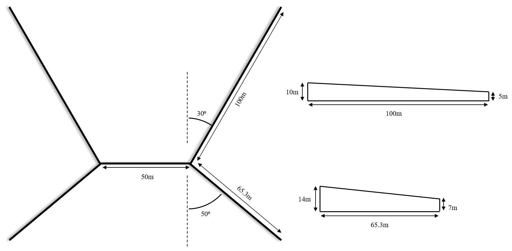
As part of the X-rotor project, a blade-resolved unsteady Reynolds-averaged Navier–Stokes (URANS) simulation of the X-rotor primary rotor was completed, as detailed in Appendix B of Giri Ajay et al. (2023). The rotor was simulated at a wind speed of 12.5 m s−1 and a tip-speed ratio of 5. The simulation was implemented in OpenFOAM (Jasak, 2009), using the κ−ω sheer stress transport closure model and the PIMPLE scheme for pressure velocity coupling. A total of 72×106 cells were used to ensure grid independence, with a domain size of 8.26 D, 5.33 D, and 4 D in the streamwise, lateral, and axial directions. The geometry of the X-rotor primary rotor is shown in Fig. 2; it is essentially made up of a pair of V-rotors, an inverted lower rotor with an inclination angle of 50°, and a standard upper rotor with an inclination angle of 30°. The relative thickness of each blade tapers from a NACA0025 section at the blade root to a NACA0008 section at the blade tip. Only the aerodynamically active portions of the rotor were simulated, neglecting both the rotor cross-arm and the tower. The blade-resolved URANS simulation inherently models dynamic stall, flow curvature, and 3D flows and therefore provides a useful case study to validate the lower-fidelity 2DAC model. Since the cross-arm was not modelled in this simulation, the 2DAC model is implemented without the strut correction in this case.
In terms of the power coefficient, the 2DAC and the URANS model predictions are in good agreement, with the 2DAC model predicting a power coefficient of 0.466, 1.4 % above the 0.460 calculated by the URANS simulation. In terms of blade forces, Fig. 3 shows the integrated normal force and tangential force on a single upper and lower blade. The azimuth angle is defined such that the upwind half of the rotor occupies 0–180°. The total tangential force on both the upper and lower blades are, in general, well reproduced by the 2DAC simulation. There is good agreement in the upwind rotor half, with the peak tangential force over-predicted by 3.1 % and 3.6 % for the upper and lower rotor, respectively. There is less agreement in the downwind rotor half, which is to be expected, as blade vortex interaction is likely to present at high tip-speed ratios and is not accounted for in the 2DAC model. For the upper rotor, the normal force is well matched in the upwind rotor half; however, the magnitude of the normal force is overestimated in the downwind rotor half. The peak normal force for the lower rotor is underestimated, and a general offset in the normal force is observed.
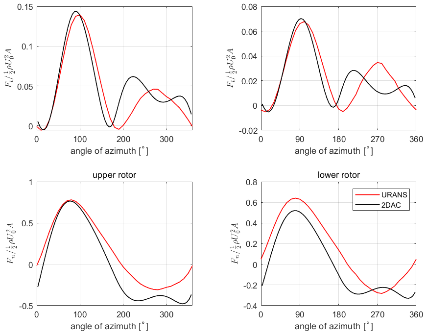
Figure 3Integrated blade force for the X-rotor upper and lower blades as a function of azimuth angle.
Due to the strong agreement in rotor power coefficients and the relatively good agreement in individual blade force profiles, the 2DAC model is considered valid for use in this study.
2.2 Rotor geometry generation
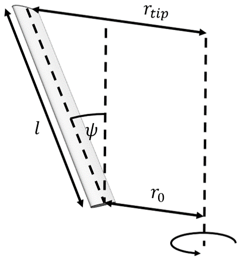
In this paper, the rotor geometry refers to the shape of the rotor swept area, independent of the blade geometry. As the rotors considered in this study are straight blades, the rotor geometry can be defined by the inner radius r0, the blade length l, and the inclination angle ψ. For generality, the blade length can be non-dimensionalised by the inner radius, ; this is equal to double the rotor aspect ratio for an H-rotor. For this study, rotor geometries are generated with and 0° 50°. The variables l, r0, and ψ are labelled in Fig. 4 for clarity. For a given rotor configuration, the frontal area can be calculated with
2.3 Blade plan-form generation
The blade designs considered within this study are split into two categories: the first are fixed-chord-length blades, and the second are blades with an optimised chord distribution. The chord length is presented as non-dimensionalised by the inner radius of the rotor, and the chord lengths considered in this study ensure that the maximum solidity at the blade root does not exceed 1, i.e.
where N and c represent the number of blades and chord length, respectively. For a two bladed rotor, the maximum non-dimensional chord length ranges from 0.5 for ψ = 0° up to 0.775 for ψ = 50°. The full range of non-dimensionalised chord lengths considered for this study is given in Table 1.
Table 1List of rotor design and operational variables permuted to generate data for this study.
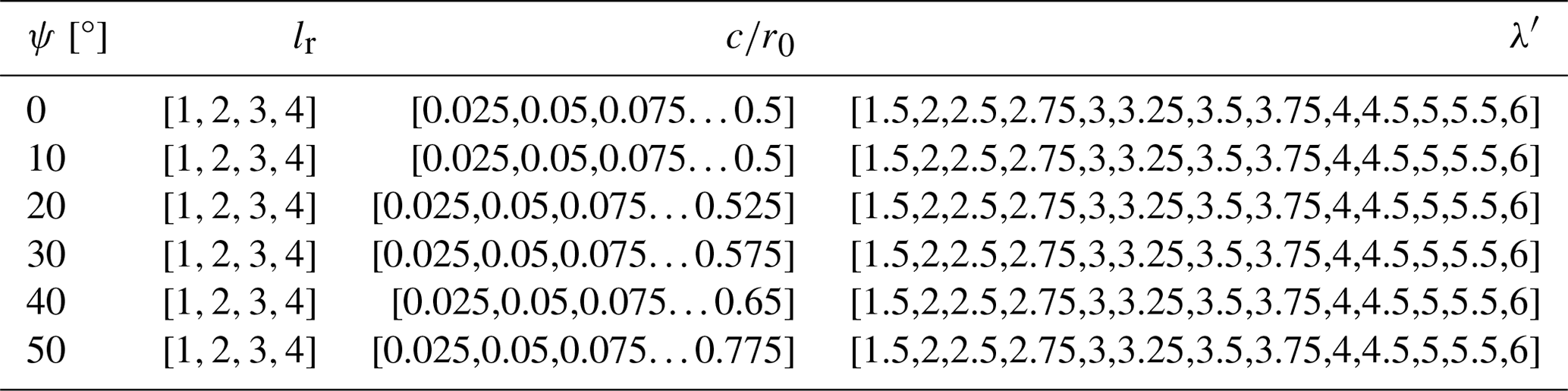
In order to find the optimum chord distribution, the 2D rotor segments are assumed independent, an assumption inherent within the 2DAC approach, and the optimum blade plan-form shape is generated through finding the chord length that locally maximises the power coefficient for each rotor segment using data from the fixed-chord-length simulations. This is applied at a specific design tip-speed ratio, λ′, with the tip-speed ratio defined as
where Ω represents the rotor speed. This approach can be repeated over a range of tip-speed ratios, , defining a set of blades optimised over a range of tip-speed ratios. The optimum blade design for power capture can then be readily identified as the iteration that maximises CP. The full range of solutions can also be explored to find potentially more practicable solutions and to identify trends within the design space. This approach can be repeated over the full range of rotor geometries, giving a set of optimal blade shapes designed for maximum CP over a 3D design space that cover λ′, ψ, and lr. The full details of the completed performed simulations are given in Table 1; in total 7332 rotor simulations were completed.
In this study the NACA0018 aerofoil section was used over the full blade length, with blade polars generated at a Reynolds number (15×106) using X-Foil (Drela, 1989) and extrapolated using the Viterna method (Viterna and Janetzke, 1982). Whilst the optimal blade plan form is dependent on the blade section used over the blade, this study is attempting to understand the general trends in rotor behaviour based on the rotor geometry rather than provide a detailed optimal design case. It is expected that trends in rotor design will be consistent over a range of symmetric aerofoils; therefore the use of a single aerofoil section is not considered a significant limitation. The NACA0018 section was selected as it is commonly used for VAWT rotors, and the Reynolds number was selected to be consistent with multi-megawatt offshore VAWT turbine concepts such as the X-rotor.
The effect of blade number is also absent from this investigation. As this study focuses on the rotor-averaged performance parameters and utilises an aerodynamic model based on revolution-averaged loads, the blade number has only two effects: firstly to modify the rotor solidity and secondly to reduce the tip losses, marginally increasing both power production and rotor loads. The dominant effect is expected to be the change in rotor solidity, which can be readily understood through an equivalent change in the blade chord through Eq. (3). Whilst the effect of blade number is not directly studied, and the effect of blade number cannot be directly obtained from the existing data due to the changes in tip losses, the trends in rotor behaviour will be reproduced in terms of solidity, and this is not considered a significant limitation to the study.
Section 3.1 presents the results of studying the effect of rotor inclination angle on fixed-chord-length blades, examining the relationship between blade inclination angle and rotor-averaged variables, including the thrust, power, and optimal tip-speed ratio. Variables pertinent to the cost of energy are introduced, and limitations on the maximum bending stress in the blade are investigated.
Next, the blade optimisation procedure described in Sect. 2 is demonstrated, and the resultant optimum blade plan-form shapes are discussed in Sect. 3.2. Finally, Sect. 3.3 evaluates the aerodynamic behaviour of rotor designs utilising the optimised blades presented in Sect. 3.2, and limitations on maximum bending stresses are once again imposed to evaluate the practicality of rotor designs.
As in the X-rotor design, presented in Sect. 2.1, the rotor blades are considered to be attached to the tower at the blade root. The effective chord length of the strut is taken as 20 % of the strut radius, equivalent to a strut chord length of 5 m for an inner radius of 25 m. For reference, the rotor swept area for rotors of different aspect ratios with an inner radius of 25 m are presented as a function of blade inclination angle in Fig. 5.
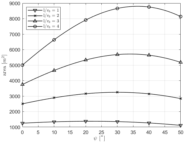
Figure 5Rotor area as a function of inclination angle for rotors of different aspect ratios.
3.1 Survey of design space fixed chord
Figure 6 displays the maximum power coefficient, the corresponding maximum power (accounting for the rotor area increase), the corresponding rotor thrust, and the optimal tip-speed ratio at which the maximum power coefficient is reached as a function of the rotor inclination angle and blade chord length. For ease of comparison, the power and thrust values are normalised by the values obtained for the optimal H-rotor at each aspect ratio. The optimal H-rotor is defined for each lr value as the H-rotor which maximises the power coefficient. The blue square marker represents the location of the optimal H-rotor design, whilst the red diamond marker indicates the design point corresponding to the largest achievable power. The grey shaded area represents the region which has not been simulated due to the restrictions on chord length discussed in Sect. 2.
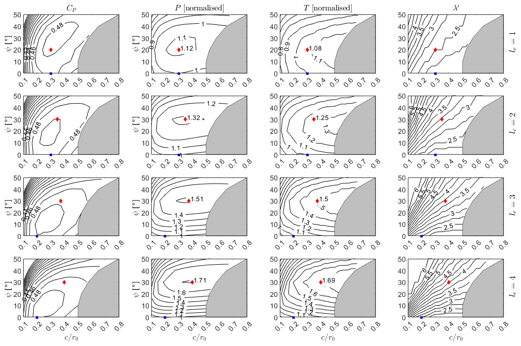
Figure 6Power output, aerodynamic thrust, and optimal tip-speed ratio for un-tapered VAWT designs, presented as a function of and ψ, with thrust and power normalised by the optimal H-rotor design. Results are shown for blade lengths of . The optimal H-rotor design is indicated by a blue square, and the optimal V-rotor design is indicated by a red diamond.
The rotors were simulated up to a maximum tip-speed ratio of 6. It is clear that with the large inclination angles and high blade lengths, the optimum power coefficient is not reached for the low chord length cases. This implies that the decrease in maximum power output for these cases is artificially smaller due to the limited search range and that a high power output may be achievable.
Whilst the potential for power gains are clear from Fig. 6, it is important to understand the effects of any rotor design on the cost of energy. At an early design stage, blade cost can be assumed to scale with blade mass, and whilst a detailed design structural design is required to obtain blade mass estimates, the blade volume can be used as a proxy variable to understand the relative change in blade mass between different designs. This is given by
where k1 represents a shape parameter, and x represents the non-dimensional spanwise coordinate. In this study, the shape parameter is constant along the blade, as a single aerofoil section is used. In addition to blade mass changes, variations in the rotor geometry, specifically the tip radius rtip, and design tip-speed ratio affect speed/torque input to the drivetrain. Assuming similarity scaling, the drivetrain torque can be used as a proxy for the generator mass and cost. The rotor torque is given by
with the rotor speed, Ω, given by
and the tip radius given by
In order to compare values over different rotor designs, it is instructive to compare rotors with equal power production, and this can be achieved through introducing the linear scaling parameter s, with
The scaling parameter defines how the length scale of rotor design (2) must be modified in order to equal the power rating of design (1). The inner radius, blade length, and blade chord scale linearly with s, and the rotor swept area, blade volume, and rotor torque then scale with Eqs. (2), (5), and (6), respectively.
A final consideration is the bending stresses within the blade. A blade with a specific material design will be capable of withstanding a certain maximum bending stress. In comparing blade designs, it is important to compare designs that have a similar maximum bending stress; otherwise material innovations are implicitly included within the comparison. Treating the blade as a simple beam, the out-of-plane bending stresses at spanwise location x and a distance δ from the structural centre of the blade (normalised by the chord length c) are given by
where represents a shape function dependent on the thickness of the aerofoil section; as a constant aerofoil section is used, k′′ remains constant. As the blade has a fixed chord length, it is clear that the maximum bending stresses occur at the blade root. For the comparison presented here, the spanwise force distribution that maximises the bending stress at the design tip-speed ratio is selected.
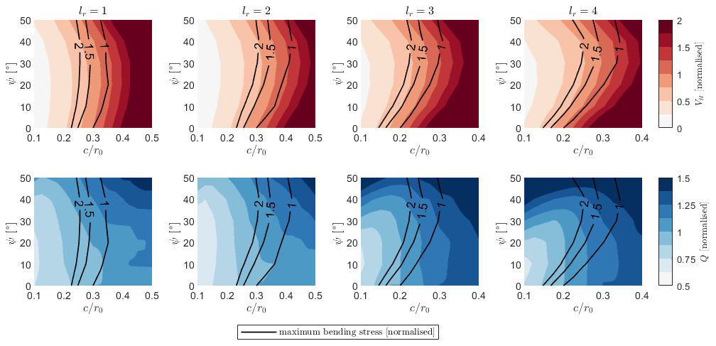
Figure 7Blade volume and rotor torque for rotors of equal rated power, normalised by the optimal H-rotor design, presented as a function of chord length and inclination angle for . Contours of maximum bending stress, normalised by the value for the optimal H-rotor, are presented alongside in black.
Figure 7 displays the blade volume and rotor torque for rotor designs of equal rated power as a function of inclination angle and blade chord length. The values are normalised by the design values for the optimal H-rotor. Alongside these contours, the maximum operational bending stresses are presented, normalised by the maximum bending stress for the optimised H-rotor. The constant blade volume contours have a positive gradient of up to 20° for the lr=1 and up to 30° for , indicating that rotors utilising inclined blades can reduce the cost of blades for rotors of the same power output. However, the maximum bending stress contours clearly indicate that inclined rotor blades are subject to larger aerodynamic bending stresses. In all cases, the gradient of the maximum bending stress contours is larger than the gradient of the blade volume contours; this implies that by moving along each constant stress contour the minimum blade volume and rotor torque are obtained at an inclination angle of 0°. This result implies that any material innovation that facilitates a blade design which can withstand larger aerodynamic bending stresses will be best applied to lower the chord length of the H-rotor design if the objective is to minimise blade costs.
Similarly, the contours of constant maximum bending stress have a larger gradient than the rotor torque contours, again indicating that the most optimal solution to reduce rotor torque, for a given blade material layup, is the H-rotor design. These results indicate that, for straight-bladed, fixed-chord-length VAWTs, inclined rotor blades do not represent an effective design innovation to lower the cost of rotor blades or drivetrains if the blade design is driven by operational loads.
3.2 Blade optimisation
The blade of a V-rotor experiences a varying local tip-speed ratio, and, at each rotor section, the chord length is normalised by a different radius to obtain the local solidity. This indicates that the optimal plan-form shape of a V-rotor blade may not be straight. The process for generating an optimal blade plan-form shape is described in Sect. 2. Figure 8 demonstrates the blade optimisation procedure at tip-speed ratios from 2.5 to 4.5, for inclination angles of 0 to 50°, and for lr=2. The solid black line represents the chord length that maximises the local power coefficient at each spanwise location. There are a number of trends that are demonstrated well by Fig. 8.
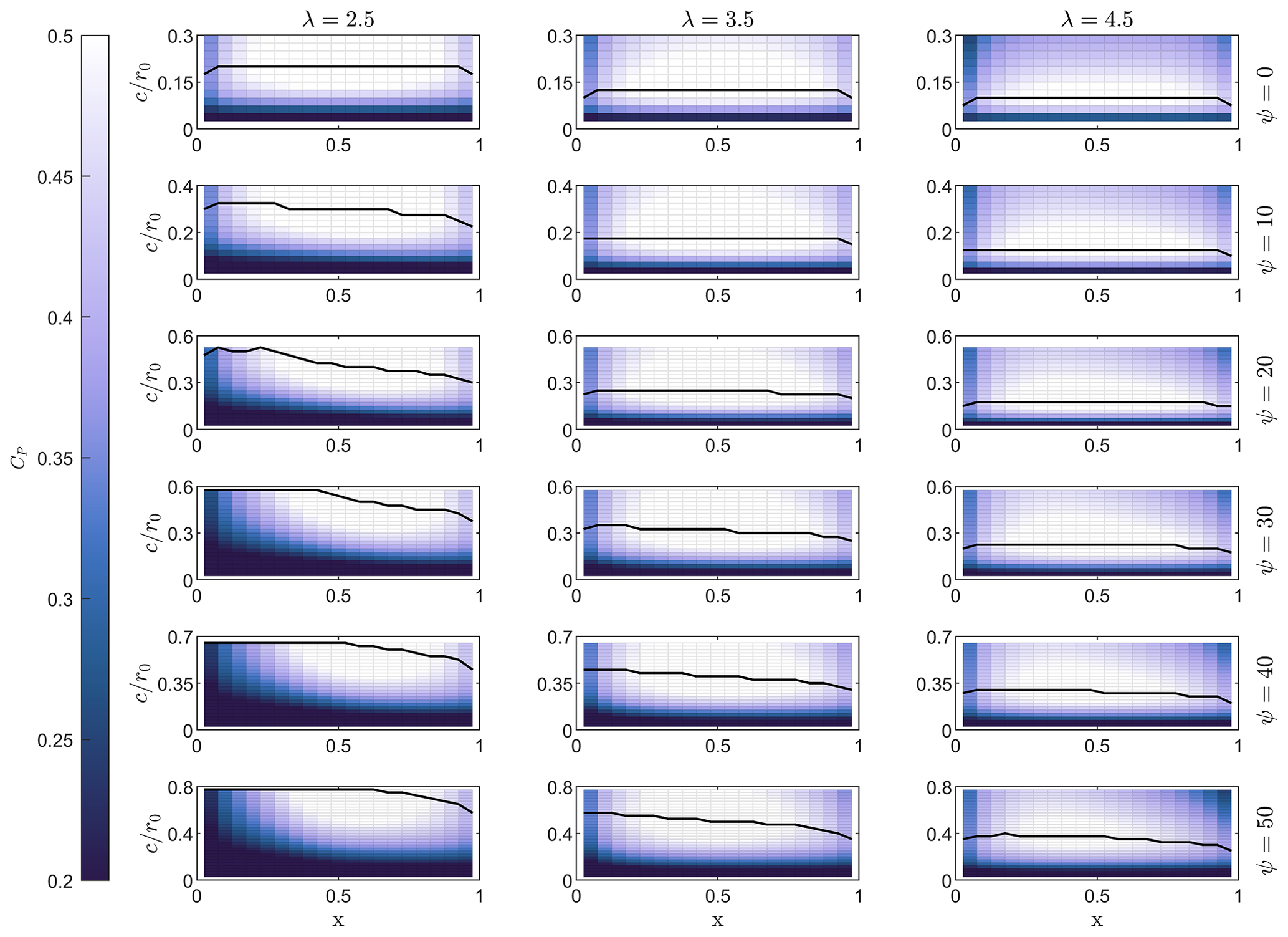
Figure 8Optimal blade plan form displayed above a power coefficient heat map for lr=2. Designs cover and . Note that the changes on the y axes scale at different inclination angles due to the variations in maximum chord length in reference to Eq. (3).
Firstly, the optimal chord length decreases as the design tip-speed ratio increases; this has already been observed in Fig. 6 where the optimal tip-speed ratio is seen to decrease with increasing chord length, as is standard for VAWTs (Hand et al., 2021). As the thrust coefficient is dependent on the product of the tip-speed ratio and the rotor solidity, to reach optimal loading any increase in tip-speed ratio should be matched by a decrease in solidity. Secondly, the optimal chord length is found to increase with increasing inclination angle. This can be understood as the chord length having to increase with to preserve the rotor solidity and therefore optimal loading.
It is also clear that the introduction of an inclination angle promotes a tapered blade. For basic momentum methods it can be shown that, if a linear lift coefficient is assumed, the rotor loading is directly proportional to the product of solidity and tip-speed ratio (Loth and McCoy, 1983). This would imply that the optimal inclined blade has a constant chord length. In reality, however, as the rotor inclination angle increases, the local tip-speed ratio decreases, moving inboard from the tip. At low local tip-speed ratios, the blade sections undergo large fluctuations in angle of attack outside of the range in which the linear assumption is valid. At large angles of attack, the blade stalls and the lift coefficient drops significantly; this means that, to ensure the rotor is loaded more optimally, the chord length must increase.
Figure 8 also demonstrates a limitation of the current study. The limitation imposed by Eq. (3) to keep the local solidity below 1 at the blade root means that the optimal chord length is not met towards the root of blade designs for high inclination angles and low tip-speed ratios. It should be noted that in most horizontal-axis wind turbine designs, the blade design towards the blade root is dominated by structural considerations and that this area would likely not be subject to aerodynamic optimisation for a realistic rotor design.
3.3 Survey of design space (optimised blade)
Figure 9 shows the power coefficient, power output, aerodynamic thrust, and blade volume for the optimised blades as a function of the inclination angle and design tip-speed ratio for each aspect ratio. Again, the power and thrust are normalised by the respective value for an optimised H-rotor, indicated by the blue square. The red diamond marks the location of maximum power capture. It is clear that the limits on maximum chord length imposed by Eq. (3) lead to sub-optimal blade design at low tip-speed ratios and high inclination angles. This can be seen as the blade volume contours begin to appear parallel with the x axis, as the blade chord cannot be further increased.
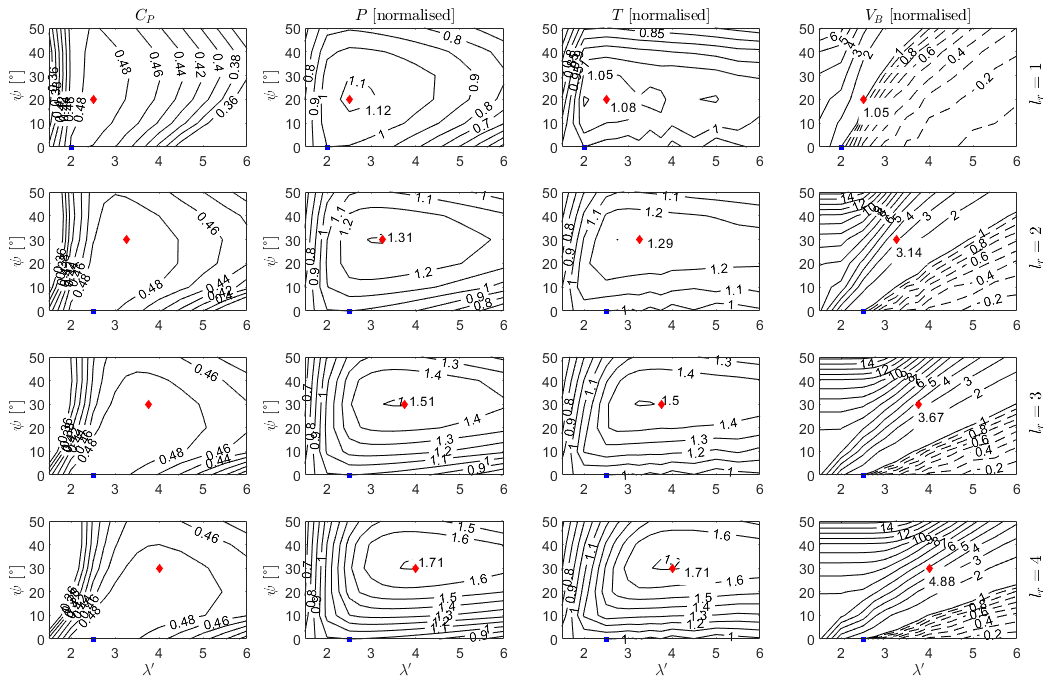
Figure 9Power coefficient, power output, aerodynamic thrust, and blade volume, normalised by the optimal H-rotor value, presented as a function of design tip-speed ratio and inclination angle for blade lengths . The optimal H-rotor design point is marked with a blue square, and the optimal design for maximum power is marked with a red diamond.
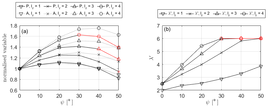
Figure 10(a) Aerodynamic power and rotor area for an optimised blade with the same blade volume as the optimal H-rotor, normalised by the optimal H-rotor value, presented as a function of inclination angle. (b) Corresponding optimal tip-speed ratio. Data where trends indicate that the optimal tip-speed ratio is beyond the tip-speed ratio limit are highlighted in red.
As previously discussed, the blade volume can be taken as a proxy for blade mass and therefore cost. It is therefore interesting to understand the maximum power output achievable by blades of equal volume to approximate the power gains that can be achieved without increased blade cost. This can be readily obtained by following blade volume contour lines equal to 1 from Fig. 9. Figure 10a shows the power output for an optimised blade of equal volume to the optimal H-rotor blade as a function of rotor inclination angle for a range of lr. This is presented alongside the relative rotor area, again normalised by the optimal H-rotor. Figure 10b shows the optimal tip-speed ratio at which the rotor operates. As is clear from the blade volume contours in Fig. 9, the tip-speed ratio range considered for this study is not sufficiently wide to obtain optimal blade designs for combinations of large inclination angles and large lr values. For rotor geometries where the normalised volume of the optimal blade exceeds unity, the trace is extended in red, and the power output for the blade optimised at a tip-speed ratio of 6 is shown.
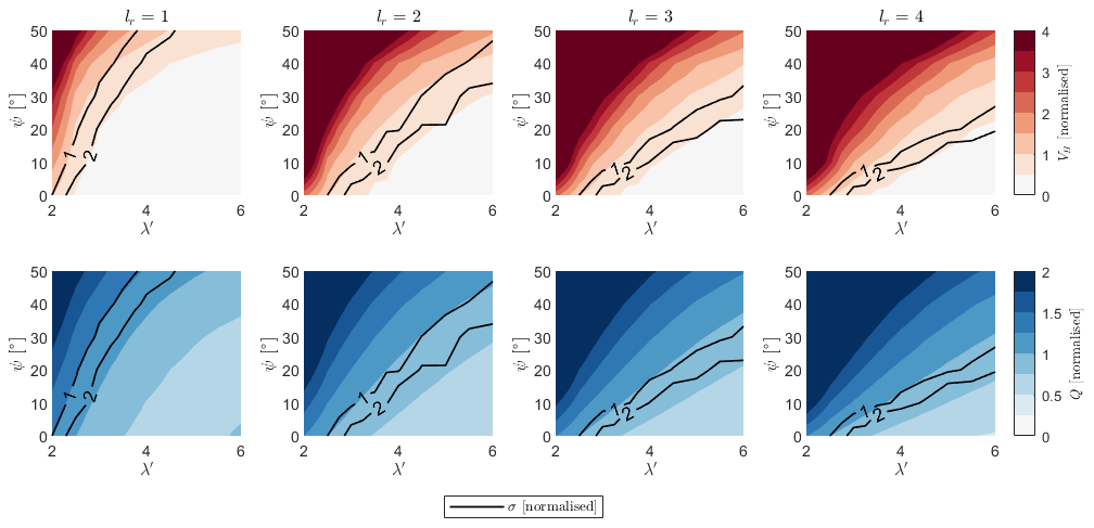
Figure 11Blade volume and rotor torque contours, normalised by the optimal H-rotor value, as a function of inclination angle, design tip-speed ratio, and blade length. Contours of constant blade stress are plotted alongside in black.
Using an identical approach to that applied to un-tapered blades presented in Sect. 3.1, the blade volume and rotor torque for rotor designs with an equal rated power are compared in Fig. 11. Contours showing the maximum bending stress, normalised by the value for the optimal H-rotor design, are shown in black. Unlike the case for un-tapered rotors, it is clear that solutions exist within the optimised space that conform to the limitation on bending stress whilst decreasing blade volume and rotor torque. Additionally, for each of the cases, if a material innovation that facilitates higher bending stresses is applied, inclined rotor solutions also exist that lower both the blade volume and rotor torque compared to an equivalent H-rotor for all the aspect ratios considered here.
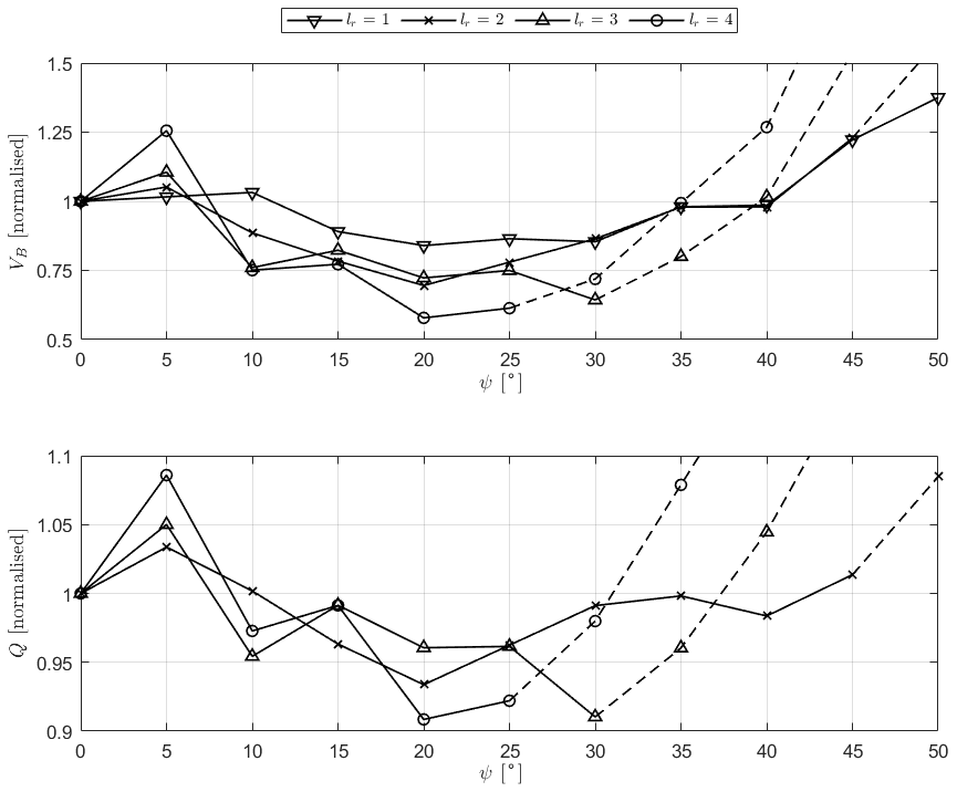
Figure 12Minimum blade volume and rotor torque, normalised by the optimal H-rotor value, for rotor designs with constrained bending stress as a function of rotor inclination angle. Dashed lines represent rotor configurations where the bending stress is below the critical limit.
Figure 12 shows the minimum blade volume and rotor torque, normalised by the optimised H-rotor design, for blade designs constrained by the maximum bending stress of the reference H-rotor as a function of rotor inclination angle. From Fig. 11, it is clear that for lr≥3, the maximum bending stress for high inclination angles is below that of the reference H-rotor. For this reason, traces at which the maximum bending stress is lower than the constraint are represented by dashed rather than solid lines. For these values, more optimal blade designs are likely to exist at design tip-speed ratios above those considered within this study. These lines are not smooth, primarily due to the coarseness of the original simulation grid in both λ′ and ψ, detailed in Table 1.
It is clear that, for all aspect ratios considered here, a decrease in both blade volume and generator torque is achievable. As the blade length increases, the potential for reductions in blade volume and rotor torque increases, with a maximum savings of 42 % in blade volume for lr=4 and ψ = 20°. A similar trend is shown in the potential reduction in rotor torque, although lower values are achievable, up to 9 % for lr=4 and ψ = 20°. It appears that there is correlation between the trends in blade volume and rotor torque, and it is clear that rotor designs exist which significantly reduce both blade volume and rotor torque simultaneously.
4.1 Un-tapered blade performance
Section 3.1 presents the aerodynamic characteristics of a range of rotor designs with rotor aspect ratio, blade chord, and rotor inclination angle acting as the free variables. Figure 6 demonstrates that significant power gains can be achieved through introducing an inclination angle to un-tapered blades, with increases of 12 %, 32 %, 51 %, and 71 % available compared to the optimal H-rotor design for blade lengths of , respectively. These power gains are obtained through an increase in rotor swept area and are therefore accompanied by an increase in thrust on the rotor by a similar value. The rotor designs which maximise the power available occur at a significantly higher chord length and therefore do not represent a design solution that would decrease the relative cost of a blade compared to the optimal H-rotor, as is shown in Fig. 7.
The blade volume and rotor torque for rotors with an equal power rating are shown in Fig. 7 and demonstrate that reductions in blade volume and rotor torque are achievable through inclining un-tapered rotor blades. However, when compared to contours showing the normalised maximum operational bending stress at the blade root, it is clear that the most effective means of blade volume reduction without exceeding limits on the maximum operational bending stress is through reducing the blade chord for an H-rotor design rather than introducing an inclination angle. This indicates that, if a constant chord distribution is employed, inclined rotor blades do not present an obvious case for a reduction in the cost of energy. It should be noted, however, that as the inclined rotor blades will be smaller in plan-form area, they will be subject to lower extreme loads in the parked case, and a more complete analysis is required to draw definitive conclusions in the case where extreme rather than operational loads are the design drivers.
4.2 Optimal blade design
A simple method of generating an optimal blade plan-form design is introduced in Sect. 2.3 and is applied in Sect. 3.2. It is clear that a taper is introduced to the blade as the inclination angle increases. The effect of the root and tip losses are shown to decrease the optimal blade chord at the blade root and tip and, aside from this effect at the blade root, the taper is monotonic. At low tip-speed ratios and high inclination angles, the local blade chord towards the blade root is limited by the solidity condition imposed by Eq. (3).
4.3 Optimal blade performance
Section 3.3 presents the aerodynamic characteristics of the rotors employing the optimal blades described in Sect. 3.2. Figure 9 demonstrates that power gains of 12 %, 31 %, 51 %, and 71 % for blade lengths of are available compared to the optimal H-rotor design. In the same manner as the un-tapered case, increases in power are matched by an approximately equivalent increase in the thrust on the rotor. Figure 9 also demonstrates the significant increase in blade volume accompanied by increasing inclination angle and decreasing design tip-speed ratio. The power gain available to rotors with a blade volume equal to the optimal H-rotor is shown in Fig. 10, with values of 8 %, 25 %, 42 %, and 62 % for blade lengths of shown to be achievable.
Figure 11 displays the change in blade volume and rotor torque for rotors with an identical power rating, demonstrating that increasing the design tip-speed ratio decreases both blade volume and rotor torque and that introducing an inclination angle increases both blade volume and rotor torque. However, when considering limitations on the maximum allowable bending stress, it becomes clear that V-rotors can reduce both the blade volume and rotor torque compared to H-rotors under the same limitations on the maximum operational bending stress. This is further exemplified in Fig. 12, where the changes in blade volume and rotor torque are shown as a function of rotor inclination angle in the case where the maximum bending stress at the blade root is limited to the value of the optimal H-rotor design. Blade volume reductions of 16 %, 30 %, 36 %, and 42 %, with corresponding rotor torque reductions of 4 %, 7 %, 9 %, and 9 % for blade lengths of , are shown to be achievable.
These results apply a structural limitation to an aerodynamically optimised design. This serves to indicate if potential solutions exist within the aerodynamically optimised space that conform to the imposed structural limitation and are not equivalent to any kind of full aero-structural optimisation. A more complete aero-structural optimisation is required to define any meaningful blade design. However, these results highlight the fact that the natural taper introduced through a purely aerodynamic optimisation can produce blade designs that conform to basic structural limitations whilst lowering the blade volume and rated torque of the rotor for a given power rating. This finding indicates that V-rotors have the potential to reduce the cost of energy compared to H-rotor designs.
In the case of horizontal-axis wind turbines, thicker aerofoil sections are typically used at the blade root to increase the second moment of area and decrease the bending stresses. Although the thicker aerofoil sections lower the local rotor power coefficient, the local power coefficient of these blade sections contributes little to the overall rotor power coefficient due to the relative swept area. V-rotors introduce a similar trend, where the swept area at the blade root is significantly lower than the blade tip, which is not the case in H-rotors. This can facilitate a similar approach to HAWT blade designs, and any future aero-structural work on V-rotor blades should include multiple aerofoil sections in order to explore this possibility.
Additionally, a key benefit identified for straight-bladed VAWT rotors is the ease of blade manufacture compared to HAWT blades. In order to maintain this benefit, a simplified chord distribution should be introduced, employing a simple linear taper rather than an aerodynamically optimised design.
This paper presents a study focusing on the effect of blade inclination angle on the aerodynamic behaviour of V-rotors, undertaken using a 2DAC aerodynamic model. The first section of the results focusses on the effect of rotor inclination angle, blade length (rotor aspect ratio), and blade chord length on the aerodynamic characteristics of VAWTs with un-tapered blades. It is demonstrated that, although significant power gains are available through using inclined rotor blades, when considering limitations on the maximum bending stress experienced by the blade, H-rotors remain the most economical option, allowing for the minimum possible blade volume and rotor torque for any given power rating.
Following this, a simple procedure for optimising the blade chord distribution for the maximum power coefficient is described and implemented. It is shown that a taper is introduced into the blade through the aerodynamic optimisation, which has potential structural benefits.
Finally, the aerodynamic characteristics of rotors employing these optimised blades are presented. It is shown that significant increases in rotor power are available through the utilisation of optimised inclined blades; however, designs at low tip-speed ratio have significantly larger blade volumes and are therefore considered un-economical. The comparison of blade volume and rotor torque for rotors of equal power utilising optimal blades demonstrates the potential for reductions in the cost of energy using V-rotors, and the natural taper introduced through optimal aerodynamic design reduces the blade root bending stress and facilitates designs that significantly reduce both the blade volume and rotor torque. These results imply potential blade cost reductions of 16 %–42 % and drivetrain cost reductions of 4 %–9 % compared to an aerodynamically optimised H-rotor.
The higher optimal tip-speed ratio of rotor designs utilising inclined blades is also a potential benefit for wind turbine concepts such as the X-rotor, where higher primary rotor tip-speed ratios are desirable to ensure efficient power conversion using secondary rotors (Morgan et al., 2024).
Future work must consider a more detailed aero-structural design, considering both fatigue and extreme loading and including inertial and gravitational loads on the blade. Additionally, the effects of rotor loads on the support structure should be considered.
This appendix discusses the effect of wind shear on the kinetic flux through a straight-bladed VAWT rotor.
The area swept by a VAWT is given by
where z represents the vertical coordinate, and r represents the rotor radius. In plane inflow, this rotor area can be used as a proxy for the power available to the turbine; however, due to the wind shear profile, the kinetic flux is non-uniform over the rotor height and should be included in this calculation. The wind shear profile can be approximated using the power law:
where U0 refers to the reference wind speed, z0 represents the sample height, and the shear exponent α is dependent on the environmental conditions but can be assumed to be 0.12 for a typical offshore site. The kinetic flux is therefore given by
where ρ represents the rotor area. The power available to the turbine is therefore given by
where can be considered the effective swept area of the turbine, weighted by the power available due to the wind shear profile. The rotor geometry can be described using the variables in Fig. 4, and length scales can be non-dimensionalized by the inner radius of the rotor. In addition to this, the rotor's location within the shear profile can be related to length scale of the rotor through minimum height zmin and the sample height z0. Here it is considered that the minimum rotor height is approximately equal to the inner radius, ; this is equivalent to a 2.5 MW H-rotor with an aspect ratio of 2 having a tip clearance equal to 25 m. The location of the sample height z0 is considered to be equal to the centre of the equivalent H-rotor, i.e. . This allows A and to be presented non-dimensionally, as shown in Fig. A1a. Comparing the effective area with the geometrical area compares the maximum power available to a rotor of a given geometry in a realistic boundary layer to the same rotor in plane inflow, with velocity equal to the reference velocity. The power available to the rotor peaks at a lower inclination angle than that which maximises the geometrical area, and the peak effective area is lower than the peak geometrical area for each aspect ratio, with a relative decrement of 0.6 % for lr=1 increasing up to 2.2 % for lr=5.
The relative difference between the effective area and the geometrical area is equivalent to the difference between the maximum power available to the turbine in sheared vs. plane inflow; this is shown in Fig. A1b.
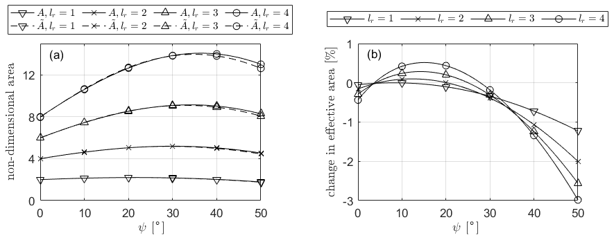
Figure A1(a) Rotor area and effective rotor area non-dimensionalised by the rotor inner radius presented as a function of rotor inclination angle for various blade lengths. (b) Relative difference between effective and geometrical rotor area presented as a function of rotor inclination angle for various blade lengths.
It can be seen that the inclusion of the effects of wind shear will decrease the expected power output for most rotor designs, with a small (< 0.5 %) increase in the power production being expected for high-aspect-ratio rotors with an inclination angle between 10 and 25°. The decrement in power available increases significantly as the inclination angle increases, up to a 3 % decrement at an inclination angle of 50°. The numerical values generated by these results are, of course, dependent on the rotor's location within the boundary layer. As the rotor moves higher into the boundary layer, the relative change in velocity over the height of the rotor decreases, decreasing the effects. However the large relative performance difference and the non-uniformity of this performance difference across both effective aspect ratio and inclination angle demonstrate the need to include wind shear effects in further evaluations of the efficacy of VAWT rotor geometries. The inclusion of wind shear effects is further complicated by the fact that the rotor power coefficient is non-uniform over the rotor height and that with a rotor designed for plane inflow, blade sections will be not be operating at their design tip-speed ratios. A full study of these effects is outwith the scope of this paper; however, the requirement for their inclusion in more precise design work has hopefully been demonstrated in this appendix.
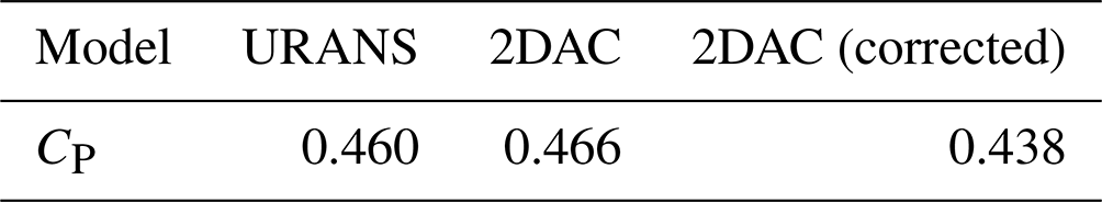
As mentioned in Sect. 2.1, flow curvature corrections are common in blade-element-based VAWT simulation codes; however, they have been derived for the case where the blade element is in the plane of rotation. The blade-resolved URANS simulation described in Sect. 2.1.1 inherently models the effect of flow curvature and therefore provides a useful validation case. The flow curvature correction described in Dyachuk and Goude (2015) has been implemented into the 2DAC model used throughout this paper and can be compared to both the base model and the blade-resolved URANS simulation. Figure B1 shows the integrated normal and tangential forces on the upper and lower blades as a function of azimuth angle. The power coefficient estimates from each model are given in Table B1. It is clear that including the curvature correction significantly reduces the performance of the code.
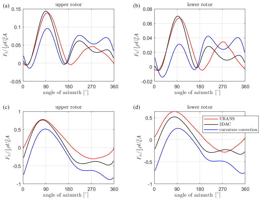
Figure B1Integrated blade force for the X-rotor upper (a, b) and lower (c, d) blades as a function of azimuth angle, including curvature correction.
Table B1Power coefficient for the X-rotor primary rotor as calculated with different aerodynamic models.
The aerodynamic simulation data are available on request from the corresponding author.
LM: study conceptualisation, simulation work, data analysis, manuscript preparation. AKA: manuscript preparation, technical review. WL: study conceptualisation, manuscript preparation. JC: manuscript preparation.
The contact author has declared that none of the authors has any competing interests.
Publisher's note: Copernicus Publications remains neutral with regard to jurisdictional claims made in the text, published maps, institutional affiliations, or any other geographical representation in this paper. While Copernicus Publications makes every effort to include appropriate place names, the final responsibility lies with the authors.
The authors would like to acknowledge Adhyanth Giri Ajay and Carlos Ferreira for the development and dissemination of the 2DAC aerodynamic code as part of the X-rotor project and for insight into VAWT aerodynamics.
This research has been supported by the EU Horizon 2020 (grant no. 101007135) and the Engineering and Physical Sciences Research Council (grant no. EP/S023801/1).
This paper was edited by Alessandro Bianchini and reviewed by three anonymous referees.
Bianchini, A., Balduzzi, F., Rainbird, J. M., Peiro, J., Graham, J. M. R., Ferrara, G., and Ferrari, L.: An experimental and numerical assessment of airfoil polars for use in Darrieus wind turbines – Part II: Post-stall data extrapolation methods, J. Eng. Gas Turb. Power, 138, 032603, https://doi.org/10.1115/1.4031270, 2016. a
Bianchini, A., Balduzzi, F., Bachant, P., Ferrara, G., and Ferrari, L.: Effectiveness of two-dimensional CFD simulations for Darrieus VAWTs: a combined numerical and experimental assessment, Energ. Convers. Manage., 136, 318–328, 2017. a
Bianchini, A., Balduzzi, F., Ferrara, G., Persico, G., Dossena, V., and Ferrari, L.: A Critical Analysis on Low-Order Simulation Models for Darrieus Vawts: How Much Do They Pertain to the Real Flow?, J. Eng. Gas Turb. Power, 141, 011018, https://doi.org/10.1115/1.4040851, 2018. a
Borg, M., Collu, M., and Brennan, F. P.: Offshore floating vertical axis wind turbines: Advantages, disadvantages, and dynamics modelling state of the art, RINA, Royal Institution of Naval Architects – International Conference on Marine and Offshore Renewable Energy 2012, London, UK, 26–27 September 2012, 33–46, 2012. a
Cordis: X-ROTOR: X-shaped Radical Offshore wind Turbine for Overall cost of energy Reduction, https://cordis.europa.eu/project/id/101007135 (last access: September 2023), 2023. a
Drela, M.: XFOIL: An Analysis and Design System for Low Reynolds Number Airfoils, in: Low Reynolds Number Aerodynamics, edited by: Mueller, T. J., Lecture Notes in Engineering, Springer, Berlin, Heidelberg, https://doi.org/10.1007/978-3-642-84010-4_1, 1–12, 1989. a
Dyachuk, E. and Goude, A.: Simulating dynamic stall effects for vertical axis wind turbines applying a double multiple streamtube model, Energies, 8, 1353–1372, 2015. a, b
Ferreira, C.: D2.1 Aero-elastic dynamic model capable of modelling the X-Rotor, Zenodo, https://doi.org/10.5281/zenodo.6967489, 2021. a
Ferreira, C. S., Madsen, H. A., Barone, M., Roscher, B., Deglaire, P., and Arduin, I.: Comparison of aerodynamic models for vertical axis wind turbines, J. Phys. Conf. Ser., 524, 012125, https://doi.org/10.1088/1742-6596/524/1/012125, 2014. a
Giri Ajay, A., Morgan, L., Wu, Y., Bretos, D., Cascales, A., Pires, O., and Ferreira, C.: Aerodynamic model comparison for an X-shaped vertical-axis wind turbine, Wind Energ. Sci., 9, 453–470, https://doi.org/10.5194/wes-9-453-2024, 2024. a, b, c, d
Hand, B. and Cashman, A.: A review on the historical development of the lift-type vertical axis wind turbine: From onshore to offshore floating application, Sustainable Energy Technologies and Assessments, 38, 100646, https://doi.org/10.1016/j.seta.2020.100646, 2020. a
Hand, B., Kelly, G., and Cashman, A.: Aerodynamic design and performance parameters of a lift-type vertical axis wind turbine: A comprehensive review, Renew. Sust. Energ. Rev., 139, 110699, https://doi.org/10.1016/j.rser.2020.110699, 2021. a, b
Huang, M.: Wake and wind farm aerodynamics of vertical axis wind turbines, Thesis, TU Delft, https://doi.org/10.1016/j.rser.2020.110699, 2023. a
IRENA: World Energy Transitions Outlook 2022: 1.5 °C Pathway, International Renewable Energy Agency, Abu Dhabi, ISBN 978-92-9260-429-5, 2022. a
Jasak, H.: OpenFOAM: Open source CFD in research and industry, Int. J. Nav. Arch. Ocean, 1, 89–94, 2009. a
Laneville, A. and Vittecoq, P.: Dynamic Stall: The Case of the Vertical Axis Wind Turbine, J. Sol. Energ.-T. ASME, 108, 140–145, https://doi.org/10.1115/1.3268081, 1986. a
Lee, J. and Zhao, F. (Eds.): Global Wind Report 2021, Global Wind Energy Council, Brussels, Belgium, https://gwec.net/global-wind-report-2021/ (last access: 9 December 2024), 2021. a
Leithead, W., Camciuc, A., Amiri, A. K., and Carroll, J.: The X-Rotor offshore wind turbine concept, J. Phys. Conf. Ser., 1356, 012031, https://doi.org/10.1088/1742-6596/1356/1/012031, 2019. a, b, c
Ljungström, O., för teknisk utveckling, S., and Vattenfallsstyrelsen, S.: Advanced Wind Energy Systems: Workshop Proceedings, Stockholm, 29–30 August 1974, no. v. 1, Liber Tryck, https://books.google.co.uk/books?id=HXWyiy3DPUsC (last access: 9 December 2024), 1974. a, b
Loth, J. L. and McCoy, H.: Optimization of Darrieus turbines with an upwind and downwind momentum model, J. Energy, 7, 313–318, 1983. a
Madsen, H., Larsen, T., Vita, L., and Paulsen, U.: Implementation of the Actuator Cylinder flow model in the HAWC2 code for aeroelastic simulations on Vertical Axis Wind Turbines, in: 51st AIAA Aerospace Sciences Meeting including the New Horizons Forum and Aerospace Exposition, Grapevine, Texas, USA, 7–10 January 2013, p. 913, https://doi.org/10.2514/6.2013-913, 2013. a
Madsen, H. A.: On the ideal and real energy conversion in a straight bladed vertical axis wind turbine, PhD thesis, Institute of Industrial Constructions and Energy Technology, Aalborg University Center, 1983. a
Marten, D., Bianchini, A., Pechlivanoglou, G., Balduzzi, F., Nayeri, C. N., Ferrara, G., Paschereit, C. O., and Ferrari, L.: Effects of Airfoil's Polar Data in the Stall Region on the Estimation of Darrieus Wind Turbine Performance, J. Eng. Gas Turb. Power, 139, 022606, https://doi.org/10.1115/1.4034326, 2016. a
Morgan, L. and Leithead, W.: Aerodynamic modelling of a novel vertical axis wind turbine concept, J. Phys. Conf. Ser., 2257, 012001, https://doi.org/10.1088/1742-6596/2257/1/012001, 2022. a, b
Morgan, L., Leithead, W., and Carroll, J.: On the use of secondary rotors for vertical axis wind turbine power take-off, Wind Energy, 27, 569–582, https://doi.org/10.1002/we.2901, 2024. a, b
Musgrove, P.: The variable geometry vertical axis windmill, in: International Symposium on Wind Energy Systems, C7[87]–C7[100], BHRA Fluid Engineering, Cambridge, 7–9 September 1976, ISBN 9780900983641, 1977. a, b
Paraschivoiu, I.: Wind turbine design: with emphasis on Darrieus concept, Presses inter Polytechnique, ISBN 9782553009310, 2002. a
Park, J.: Simplified Wind Power Systems for Experimenters, Helion, https://books.google.co.uk/books?id=iMAQAQAAMAAJ (last access: 9 December 2024), 1976. a
Prandtl, L., Betz, A., Klassiker der Strömungsmechanik, G., and Abhandlungen, V.: Vier Abhandlungen zur Hydrodynamik und Aerodynamik, https://doi.org/10.17875/gup2010-106, 1927. a
Price, T. J.: UK large-scale wind power programme from 1970 to 1990: the Carmarthen Bay experiments and the musgrove vertical-axis turbines, Wind Engineering, 30, 225–242, 2006. a
Rainbird, J. M., Bianchini, A., Balduzzi, F., Peiró, J., Graham, J. M. R., Ferrara, G., and Ferrari, L.: On the influence of virtual camber effect on airfoil polars for use in simulations of Darrieus wind turbines, Energ. Convers. Manage., 106, 373–384, https://doi.org/10.1016/j.enconman.2015.09.053, 2015. a
Robotham, A., Sharpe, D., Taylor, D., and Boyle, G.: Further Developments in the Taylor 'V' Type VAWT Concept, in: Intersol 85: 9th Biennial Congress of the International Solar Energy Society, Montreal, Canada, 23–29 June 1985, https://doi.org/10.1016/B978-0-08-033177-5.50383-5, 2042–2046, 1985. a
Sharpe, D.: Refinements and developments of the multiple streamtube theory for the aerodynamic performance of vertical axis wind turbines, in: Proceedings of the 6th British Wind Energy Association Conference, Reading, UK, 28–30 March, 148–159, ISBN 978-0521268998, 1984. a
Sharpe, D. and Taylor, D.: Preliminary investigations into an innovative vertical axis wind turbine, World Solar Energy Congress, Perth, Australia, 14–19 August, 1983. a, b, c, d
Sharpe, D., Taylor, D., and Boyle, G.: Developments with the “V”-type vectical axis wind turbine, in: Proceedings ofthe 9th British Wind Energy Association Conference, Edinburgh, UK, 1–3 April 1987, 221–224, 1987. a
Shires, A.: Design optimisation of an offshore vertical axis wind turbine, P. I. Civil Eng.-Energy, 166, 7–18, https://doi.org/10.1680/ener.12.00007, 2013a. a, b, c, d, e, f
Shires, A.: Development and evaluation of an aerodynamic model for a novel vertical axis wind turbine concept, Energies, 6, 2501–2520, https://doi.org/10.3390/en6052501, 2013b. a, b
Sutherland, H. J., Berg, D. E., and Ashwill, T. D.: A Retrospective of VAWT Technology, Sandia National Laboratories, SAND2012-0304, 1–64, https://doi.org/10.2172/1035336, 2012. a
The Open University: Wind Turbine Types, in: Can Renewable Energies Power the World?, p. 289, https://www.open.edu/openlearn/science-maths-technology/can-renewable-energy-sources-power-the-world/content-section-overview (last access: 9 December 2024), 2015. a, b
Viterna, L. and Janetzke, D.: Theoretical and experimental power from large horizontal-axis wind turbines, NASA Technical Memorandum, https://doi.org/10.2172/6763041, 1982. a
Willmer, A. C.: Wind tunnel tests on a 3 m diameter Musgrove windmill, International Journal of Ambient Energy, 1, 21–27, https://doi.org/10.1080/01430750.1980.9675710, 1980. a, b