the Creative Commons Attribution 4.0 License.
the Creative Commons Attribution 4.0 License.
 | 13 May 2026
Design and simulation of a continuously variable hydraulic power-split drivetrain for wind turbines
Pascal Seifermann
Jonathan Schaaf
Sven Störtenbecker
Alexander Dam
Peter Dalhoff
This paper presents the development and analysis of a novel drivetrain concept for large-scale wind turbines. The proposed concept builds on a predominantly mechanical transmission, with a small fraction of power transferred by a hydraulic system. The hydraulic power path, an adjustable hydrostatic transmission with a pump and a motor, enables full rotational speed variability while transmitting only a limited portion of the total power. As a result, a higher overall efficiency can be achieved compared to fully hydrostatic drivetrains. Furthermore, it is possible to couple the generator directly to the grid, thus omitting the frequency converter which contributes to system complexity, losses, and failure susceptibility.
A simulation model incorporating component-level loss representations is developed to evaluate different transmission layouts and design variants. It is investigated whether a hydromechanical power-split drivetrain can achieve efficiency and energy yield levels comparable to conventional geared drivetrains while referring to the characteristics of currently available hydraulic components.
The results show that the drivetrain efficiency strongly depends on the transmission layout and the site-specific wind conditions. While lower efficiencies are observed for sites with low mean annual wind speeds, specific design configurations achieve high efficiencies and energy yields comparable to those of a conventional geared reference drivetrain at sites with higher mean annual wind speeds. Overall, this paper extends previous research by minimizing the rated power of the hydraulic power path, estimating efficiencies for different drivetrain configurations, and looking into a mechanical design.
- Article
(4900 KB) - Full-text XML
- BibTeX
- EndNote


The share of wind energy in global electricity generation continues to grow, reaching double-digit percentages of the energy mix in many countries (World Wind Energy Association, 2024). With further ambitious expansion targets and an increasing need for repowering existing wind farms, increasing the energy yield and reducing the costs of wind turbine generators (WTGs) are required, while drivetrain technologies must also be adapted to new grid requirements. In addition to achieving high efficiencies, the provision of physical rotational inertia by decentralized generation units, compensating for the loss of inertia from large centralized power plants, is becoming increasingly important in grids with a high share of renewable energy.
Conventional wind turbine drivetrains are commonly based on a purely mechanical power transmission where the power is transmitted by a mechanical multiple-stage gearbox or directly fed into a generator. Variable-speed operation is enabled by a frequency converter. First attempts to decouple rotational speed of the rotor and the generator over the full range of rotor speeds were made by introducing fully hydrostatic drivetrains. They allow for the omission of the frequency converter and operation of the generator directly coupled to the grid. This is expected to reduce electrical component failure rates and wind turbine downtime. In those drivetrains, the entire power is transmitted hydraulically via pumps and motors, offering high operational flexibility but typically at the expense of efficiency. In contrast, power-split drivetrains combine a direct mechanical power path with a continuous variable transmission (CVT), which can be electrical, mechanical, hydrostatic, or hydrodynamic. Comparable to a double-fed asynchronous generator, only a small fraction of the power is transmitted by the CVT, and the main share is transmitted by the mechanical part. In comparison to a fully hydrostatic drivetrain, such a hydromechanical power-split drivetrain allows higher efficiency while still enabling variable-speed operation and inertia-conscious grid integration.
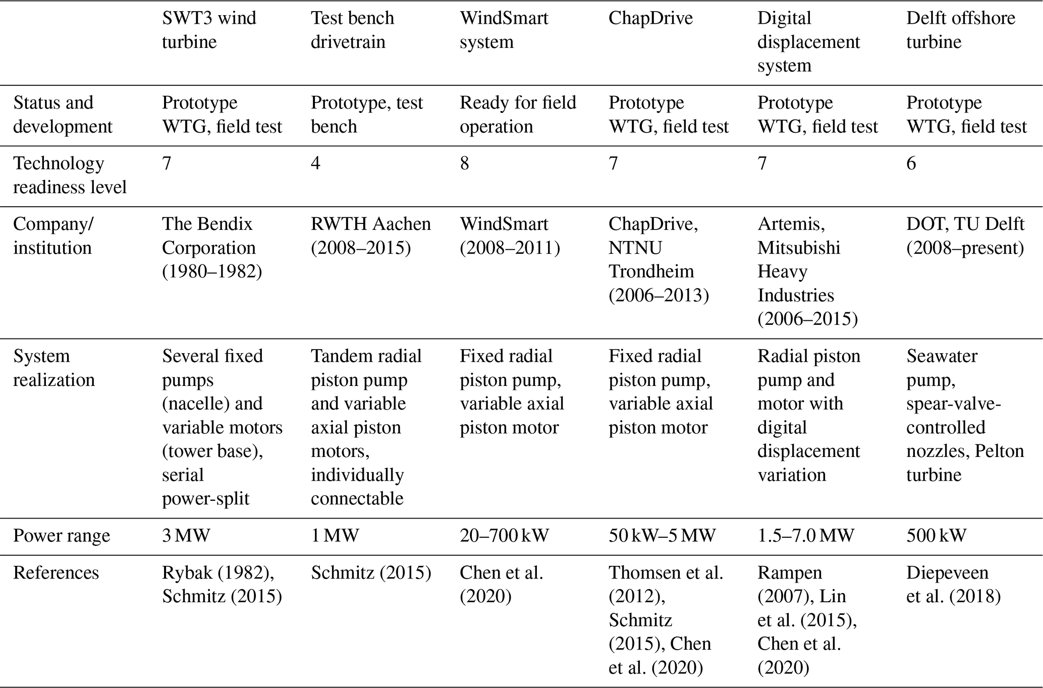
Drivetrains based on hydraulic power transmission have been the subject of research for many years, leading to the development of a wide range of concepts. Table 1 presents an overview of fully hydraulic transmission concepts from recent years, including only those that have been realized at least at laboratory test bench level. A detailed overview of more hydraulic concepts can be found in Mahato and Ghoshal (2019), Chen et al. (2020), and Taherian-Fard et al. (2020). For all fully hydrostatic drivetrains that have been realized at prototype scale, results indicate that the overall drivetrain efficiency from rotor to generator remains below that of conventional wind turbines, which ranges about 89 %–94 % (Hau and Siegfriedsen, 2025; Zhang et al., 2025; Song et al., 2023; Bak et al., 2013). To date, none of these concepts has advanced beyond the prototype stage.
In order to mitigate the issue of comparatively low efficiencies, power-split concepts have been developed. In these configurations, the majority of the power is transmitted through a mechanical path, while only a small fraction is routed via a hydraulic or electric continuously variable path, which is expected to result in a higher efficiency when compared to a fully hydrostatic drivetrain.
Rybak (1982)Schmitz (2015)Schmitz (2015)Chen et al. (2020)Thomsen et al. (2012)Schmitz (2015)Chen et al. (2020)Rampen (2007)Lin et al. (2015)Chen et al. (2020)Diepeveen et al. (2018)Table 1Overview of fully hydrostatic drivetrain concepts for wind turbines with estimated technology readiness levels (TRLs).
In the present work, a basic power-split drivetrain concept (HyDrive) is presented, and different variations in the power extraction side and gear ratios are examined. A simulation model is developed in MATLAB/Simulink, enabling efficiency assessments and comparisons with a conventional wind turbine configuration. Additional aspects of such a drivetrain are examined, including a mechanical design and the capability to provide physical rotational inertia for grid stability.
Power-split drivetrains are well established in the commercial vehicle sector and have been used since the 1990s as the primary drivetrain in agricultural machinery (Yu et al., 2019). For example, Fendt introduced their Vario drivetrain in 1996 (Matthies and Renius, 2021; Dziuba and Honzek, 1997) as the first series-produced power-split tractor drivetrain. Power-split drivetrains combine the advantages of both mechanical and hydrostatic power transmission. The power-split configuration enables a predominantly mechanical power transfer with high efficiency while still providing full variable-speed capability via the secondary path. Such a drivetrain offers a fixed gear ratio when the variable component is not engaged. This results in an operating point where the input speed equals the output speed multiplied by the fixed transmission ratio.
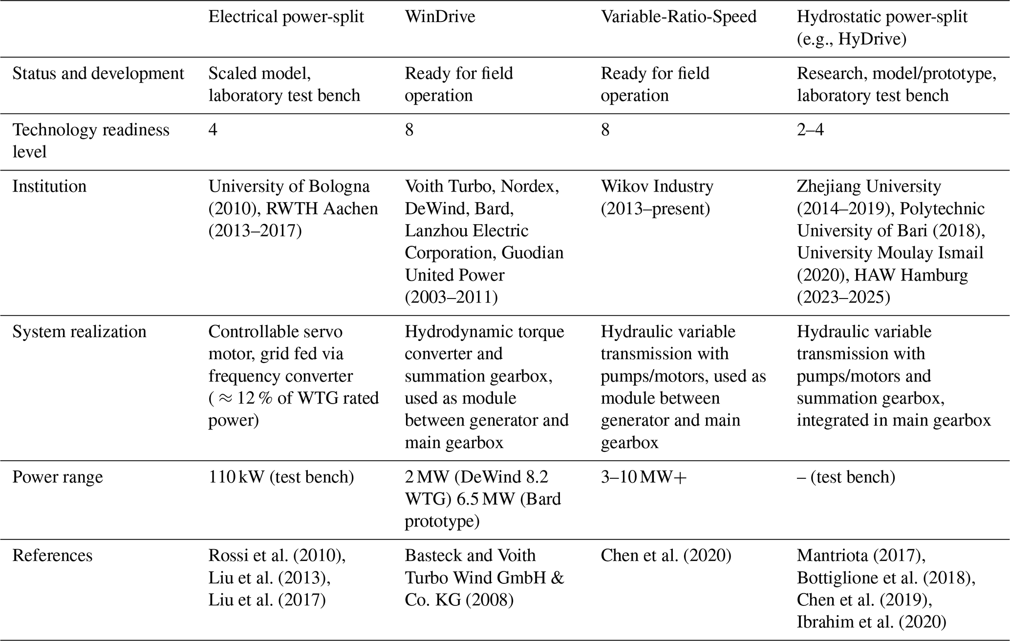
Researchers and industry have been working on different concepts with an electrical, hydrodynamical, or hydrostatic secondary path. A selection of concepts is listed in Table 2. Further information about power-split concepts can be found in Chen et al. (2020), Mahato and Ghoshal (2019), and Liu et al. (2023).
The Voith WinDrive concept was the first commercial attempt to build a wind turbine generator (WTG) with a power-split drivetrain in the 2000s. Instead of employing a hydrostatic pump–motor combination, as in most comparable concepts, a hydrodynamic converter was used to enable speed variability. The first prototype WTGs were built; however, the reasons why the concept did not achieve broader market adoption remain unclear (Basteck and Voith Turbo Wind GmbH & Co. KG, 2008).
Rossi et al. (2010)Liu et al. (2013)Liu et al. (2017)Basteck and Voith Turbo Wind GmbH & Co. KG (2008)Chen et al. (2020)Mantriota (2017)Bottiglione et al. (2018)Chen et al. (2019)Ibrahim et al. (2020)Table 2Overview of power-split drivetrain concepts for wind turbines with estimated technology readiness levels (TRLs).
Several publications have already addressed power-split gearboxes with hydrostatic power splitting. Mantriota (2017) investigated various arrangements of the split path and identified an optimal configuration among the variants studied. The focus was on the power take-off side and the direction of power flow. The results indicated a configuration in which the maximum design power of the split path could be minimized. For this configuration, referred to hereafter as the rotor-side power-split concept, the maximum transmitted power through the split path was limited to 10 % of rated power. With 15 %, the generator-side power take-off is still in a relevant design range and was therefore also considered in the following.
Building on this, Bottiglione et al. (2018) compared the efficiency of such a system with that of a fully hydrostatic drivetrain and reported an efficiency increase of up to 11 % in favor of the hydromechanical drivetrain. Chen et al. (2019) presented a hydromechanical power-split transmission for wind turbines that achieved high efficiency around rated wind speed, provided variable-speed control below rated conditions, and mitigated torque fluctuations above rated operation to protect the drivetrain. Their findings were supported by a MATLAB/Simulink–AMEsim cosimulation model and validated with test bench experiments on a 30 kW demonstrator.
A basic drivetrain concept is proposed, building on the variants discussed in Mantriota (2017) and the concept examined in Chen et al. (2019). The concept features a rotor-side power split, which introduces challenges due to the low and variable rotational speeds of the hydraulic pump. The rotor speed must be controlled according to the desired tip speed ratio (TSR) to maintain the required rotor speed. The synchronous generator is connected directly to the grid without using a frequency converter. Consequently, the generator operates at a fixed rotational speed proportional to the grid frequency, depending on its pole pair number (Hau and Siegfriedsen, 2025; Mantriota, 2017). In order to control the rotor speed, the gearbox transmission ratio has to be adjustable.
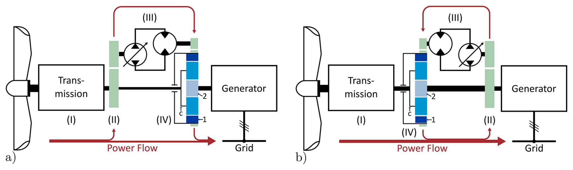
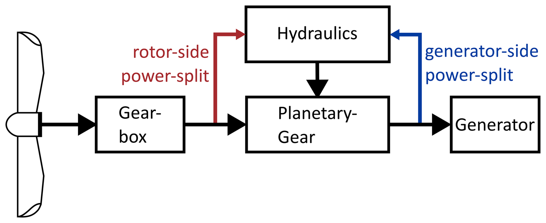
Figure 1Schematic structure of the proposed drivetrain with (a) rotor-side power split and (b) generator-side power-split. The drivetrain consists of a fixed-ratio two-stage planetary transmission (I), a power-splitting spur gear (II), a continuously variable hydraulic transmission (III), and a third planetary stage as the summation stage (IV). The planetary stage consists of a ring gear (dark blue, index 1), carrier with planets (medium blue, index c), and sun gear (light blue, index 2). Power flow indicated in red.
For this purpose, a conventional three-stage wind turbine gearbox is modified. The ring gear of the third stage is changed in such a way that it can freely rotate and can be driven by a hydraulic motor. Altering the rotational speed of this ring gear influences the rotor shaft speed and therefore the overall transmission ratio of the gearbox. The drivetrain (Fig. 1) consists of four main elements: (I) a mechanical transmission with a fixed gear ratio, (II) a spur gear serving as the power-split, (III) a hydraulic CVT, and (IV) a planetary gear acting as a power-summing and speed-superposition stage. A fraction of the power is extracted by a hydraulic pump with continuously variable displacement, transferred to a hydraulic motor, and reintroduced into the drive shaft via the planetary gear. Within the planetary stage, the rotational speeds of the sun and ring gear are superimposed to result in the carrier speed. Figure 1 shows rotor- and generator-side power-split. Rotor-side power-split is used as the standard case if not mentioned otherwise.
If the hydraulic motor does not rotate, the ring gear is fixed, and the transmission ratio of the third stage corresponds to the stationary gear ratio defined by the tooth numbers of ring gear (1) to sun gear (2) (Müller, 1998), a status which is further called direct transmission:
The stationary gear ratio describes the speed ratio from sun gear and ring gear with the carrier being fixed. For the examined application, the more relevant ratio is the one between the carrier (rotor speed) and the sun gear (generator speed) when the ring gear is locked. This can be derived from the stationary gear ratio:
One of the key design challenges is to determine an optimal stationary gear ratio for the third planetary stage in order to maximize the overall gearbox efficiency. This gear ratio directly affects the torque ratio and, consequently, the required hydraulic power, which is discussed in more detail later.
The ring gear can be driven in both positive and negative directions. The resulting rotational speeds can be obtained using the fundamental speed equation of planetary gears (Willis equation) (Müller, 1998). This equation can be used to calculate the necessary rotational speeds of the ring gear:
All calculations and simulations in this paper are based on a modified version of the 10 MW DTU reference wind turbine (RWT) (Bak et al., 2013). This turbine features a two-stage transmission with an overall transmission ratio of 50. Rotor speeds in standard configuration range from 6 to 9.6 rpm. The speed curve used is simplified as the 10 MW DTU RWT curve differs significantly from a TSR-optimal speed curve (see Fig. 2). In addition, a slightly reduced nominal speed results when designed according to an optimal TSR. Rated generator speed and subsequently the transmission ratio were altered to feature a simpler standardized four-pole-pair permanent magnet synchronous generator. Table 3 shows an overview of the key parameters and the modifications made.
Table 3Key attributes of the 10 MW DTU RWT and the HyDrive concept.
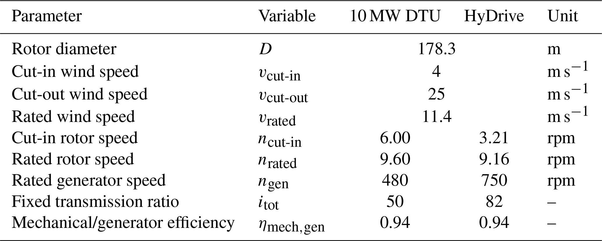
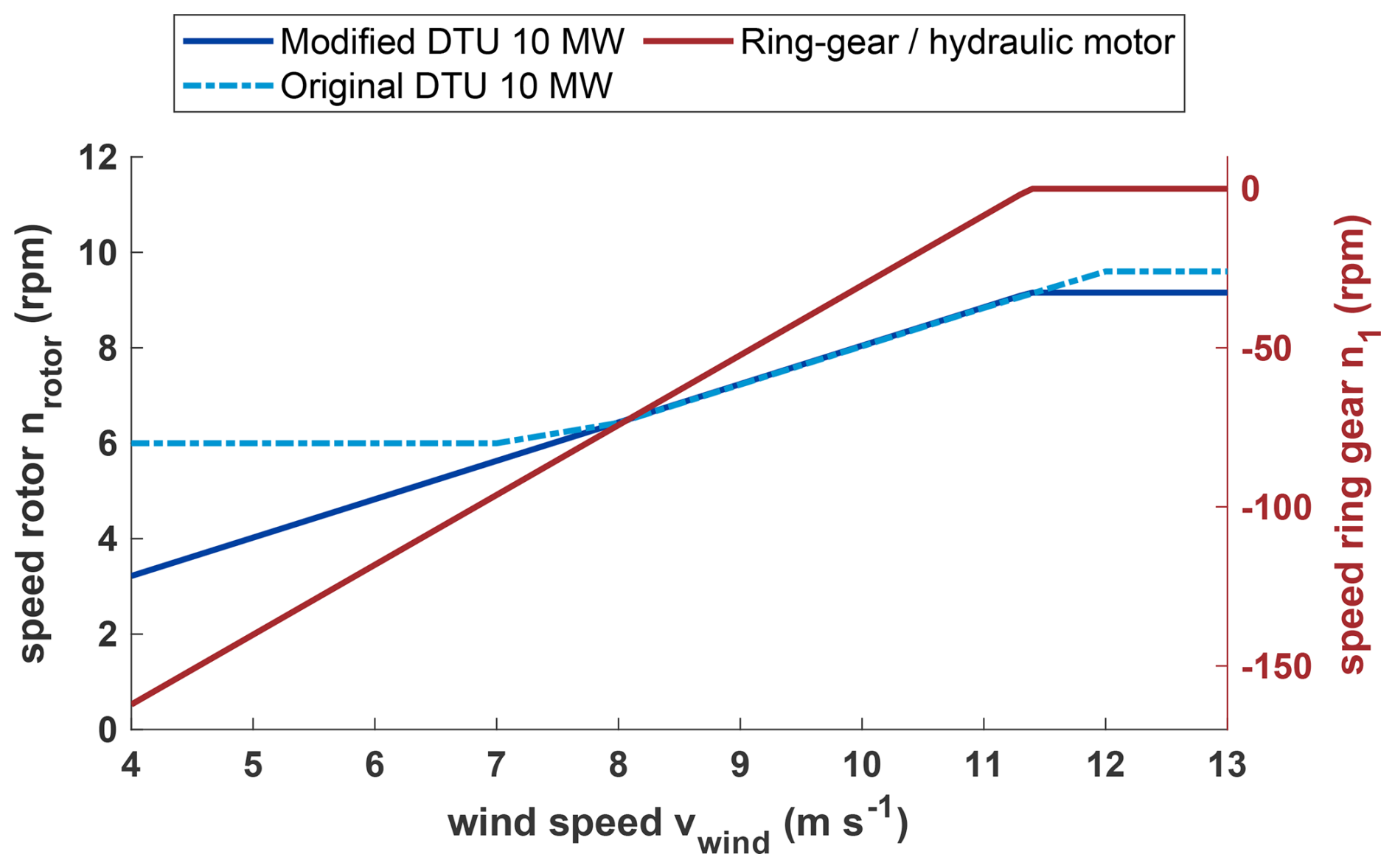
Figure 2Rotor speed comparison of 10 MW DTU RWT (modified and unmodified) and required ring gear speed. Direct transmission at rated wind speed (see Sect. 4.2). The sign indicates the direction of rotational speed.
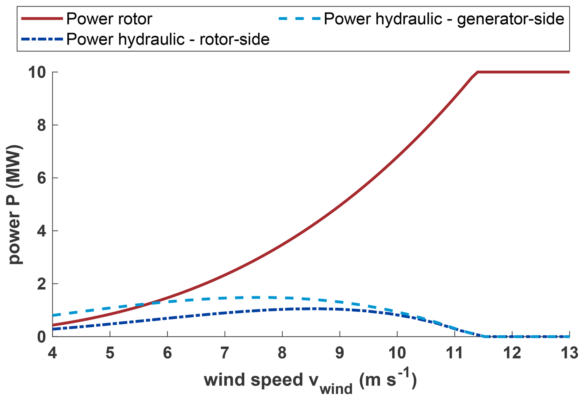
Figure 3Demanded hydraulic power and rotor power over wind speeds (lossless). Direct transmission at rated wind speed (see Sect. 4.2).
In addition to the speed ratios of the three shafts in the planetary gear, the torque distribution is also defined by the stationary gear ratio i12. Accordingly, the following relation holds:
The torque ratios remain constant. Consequently, any change in the rotor torque, which is transmitted to the planetary gear via the carrier, results in a proportional change in the torques acting on the other two shafts. The hydraulic motor is connected to the ring gear, while the generator is coupled to the sun gear, as suggested by Chen et al. (2019) and shown in Fig. 1.
Based on these assumptions and equations, the amount of power transmitted through the hydraulic path can be determined. For this, a simple calculation model in MATLAB is employed to generate power curves for different scenarios. The TSR-optimal rotor speed curve (see Fig. 2, “Modified DTU 10 MW”) is applied as input at the rotor shaft, while a constant generator speed of 750 rpm is imposed at the sun gear. The resulting speed difference between the rotor and generator must then be balanced by the ring gear, which is driven by the hydraulic motor. The required rotational speed of the ring gear is shown in Fig. 2. These ring gear speeds are necessary to maintain the optimal rotor speed and enable speed variability.
When it is assumed that the hydraulic system can follow the prescribed speed curve, the corresponding torque and power curves can be derived from the following relations between the rotor shaft torque and the torques at the ring and sun gears, respectively (Müller, 1998):
The power curve of the rotor and the ring gear and therefore the hydraulic system is shown in Fig. 3. This calculation allows for a first insight into the magnitude and profile of the hydraulic power at different wind speeds. Notably, for the generator-side power-split configuration, the hydraulic power exceeds the rotor power at wind speeds below 5.5 m s−1, which is further discussed in Sect. 5.1. To analyze this behavior and to assess its implications for drivetrain design, a dynamic MATLAB/Simscape model is developed. The model is used to investigate different design variations, such as switching the power-split location to the generator shaft and adjusting the overall transmission ratio. The results of this analysis, focusing on the optimization of the maximum rated hydraulic power and the transmitted energy, are presented in the following sections.
3.1 Simulation model
The simulation model is implemented in MATLAB/Simscape, where the system dynamics are simulated in the time domain. This model is used to calculate and compare the drivetrain efficiency to a conventional gearbox drivetrain with a frequency converter. The model is required to represent different design variants. This necessitates a precalculation of the required hydraulic power in order to size the hydraulic components, as the maximum hydraulic power depends on the specific drivetrain concept (see Sect. 4.3). MATLAB/Simscape provides different basic components like gear stages, hydraulic components, and a turbine model. The turbine model retains some limitations, as it is not possible to implement a fully resolved turbulent wind field as an input parameter for the simulation but only using the mean hub height wind speed instead. This model uses a quasistatic table approach to calculate power and thrust force to feed the dynamic drivetrain. Both limitations affect the aerodynamic simulation significantly. For this reason, a standard-case turbine is also developed to resemble a simple model of the 10 MW DTU turbine in MATLAB/Simscape to allow a direct comparison. The DNV Bladed aeroelastic wind turbine simulation software is used to validate the simple standard turbine model and to assist with plausibility checks of the HyDrive model.
Both models use a basic pitch controller to limit aerodynamic power above rated wind speed. The standard-case turbine model uses a generator torque controller, whereas the HyDrive generator is fixed in speed. A speed controller is developed to control the rotor speed through varying the hydraulic motor speed (see Sect. 3.3).
Designing the hydraulic components requires initial estimates of the hydraulic power associated with the selected direct transmission. Using the Willis equation (Eq. 3) and the hydraulic efficiency, the hydraulic components are scaled to the corresponding power class according to scaling laws (see Sect. 3.2). Further information regarding the implemented efficiencies can be found in Sect. 5.
The resulting model is thus capable of simulating any direct transmission that is specified, and it is also possible to switch the power-split side. The target of this model is to determine the optimum from many different model configurations, which requires this flexibility of the model to produce comparable results. This flexibility inevitably requires some simplifications in the design of the hydraulic components, which is why efficiency values may be increased by specifically optimizing a single design case.
3.2 Mechanical design
A first draft of the HyDrive drivetrain was visualized as a simplified 3D CAD model with a coarse preliminary sizing of the individual components to capture key design features and enable volume and mass estimates. The gearbox CAD model, shown in Fig. 4, represents a rotor-side power-split layout and forms part of a three-point mount drivetrain arrangement integrated in a wind turbine based on the DTU 10 MW RWT design (Bak et al., 2013).
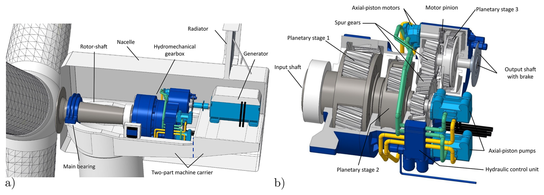
Figure 4CAD design of the proposed hydromechanical power-split transmission wind turbine. (a) Cross-section of the nacelle with the proposed drivetrain. (b) Cross-section of the gearbox with two hydraulic pumps and motors.
Beyond the general arrangement of the drivetrain components, particular attention was given to the gearbox. The key dimensions for the CAD model were preliminarily determined through first-order sizing of the gears and the hydraulic machines, based on anticipated static loads, which were derived from the nominal output power of the wind turbine and the required total transmission ratio (see Table 3). For the distribution of the mechanical and hydraulic power flows, a direct transmission at rated wind speed is assumed (see Figs. 2 and 3). Total mechanical losses are estimated to be 1 % for each planetary stage and 2 % for the spur gear stage (Hau and Siegfriedsen, 2025). The calculations are performed using standard analytical formulas for involute gears and hydraulic systems. While in line with the primary purpose of visualization, variable hydraulic losses, detailed load analyses, and microgeometry optimization are not included. Technical data and envelope dimensions from reference components were further adapted to the HyDrive power class by means of similarity scaling. While this approach is effective for visualizing the HyDrive concept, it limits the accuracy of mass estimates. The mechanical design deviates from the conceptual design in some areas: to enable a compact integration of the hydraulic system into the drivetrain, the number of pumps and motors is increased to two each. As a result of this configuration, the power load transmitted by each individual machine is limited to a fraction of the total power output of the hydraulic system, thereby addressing the fact that hydraulic components in the 1 MW range are barely commercially available. In addition, a spur gear stage is inserted between planetary stages 2 and 3 (see Fig. 4b) to allow lateral displacement for cable entry into the hub. Since the selected transmission ratios of the individual stages are deliberately conservative, the additional spur gear could potentially replace the third planetary stage entirely, provided that the transmission ratios of the remaining stages are increased accordingly. In this configuration, the second planetary stage must be designed as the summation stage. With that, material and mass could be reduced.
3.3 Controlling
The overall control concept of the HyDrive system differs from conventional converter-based systems because the generator is directly coupled to the grid and consequently follows the grid frequency. The synchronous speed is set by the number of pole pairs:
where f is the grid frequency and p the number of pole pairs. For the HyDrive drivetrain, a simple permanent-magnet synchronous generator (PMSG) with few pole pairs is chosen to reduce costs, volume, and mass compared to lower-speed generators. Accordingly, a four-pole-pair machine was assumed, yielding a synchronous speed of nsyn=750 rpm at the European 50 Hz grid.
The overall control strategy must be adapted to accommodate the generator's direct grid coupling. Standard turbine operation is partitioned into partial load and full load, with a transition (blending) region in between (Hansen and Henriksen, 2013). Separate main controllers are employed in the two regions. In partial load, a generator-torque controller enforces TSR-optimal operation by setting the electrical counter-torque according to Hau and Siegfriedsen (2025) with rotor speed nrot and optimal mode gain K:
In full load, a rotor-speed-based pitch controller maintains the rotor at rated speed, while the generator torque is held at its rated set point. With a grid-synchronized generator, the generator speed is locked to the grid frequency. As long as the torque stays below the pull-out torque, synchronism is maintained, so no generator torque controller is required. Consequently, no generator-torque controller is used to control speed in partial load. However, since the grid sets the generator speed, TSR-optimal operation must be achieved by actuating the hydraulic path to adjust the rotor speed via the planetary kinematics. The speed controller adjusts the hydraulic speed by modulating the displacement volume of the pump so that the resulting carrier speed tracks the TSR set point. The demanded rotation speed at the ring gear to achieve TSR-optimal operation at the carrier can be determined by applying the Willis equation (Eq. 3) using the sun (generator) speed and the transmission ratio i12. While the rotor speed is regulated through the hydraulic circuit, there is no possibility to control torque in the planetary gear, as the torque ratio is always fixed; see Eq. (4). For a given rotor power condition (at TSR-optimal speed), there is an associated rotor torque which demands specific torques at ring and sun gear. This means that, in full load, there is no need for a generator torque controller as well, as the generator torque follows the demanded torque from the last planetary stage. There is a standard pitch controller needed to limit aerodynamic power and rotor speed. Both the pitch and the hydraulic controller aim at the same set point (rated rotor speed), which can lead to counteraction. To avoid interference, control authority is separated: the pitch controller has priority and limits aerodynamic power input in the drivetrain system, while the hydraulic controller is subordinated and limited to minor corrections around the set point.
3.4 Controlling challenges
As previously stated, with rotor-side power extraction, the ring and sun gear torque proportionally depends on the carrier torque of the rotor shaft. When taking power off the drivetrain before the last planetary stage, an interaction of carrier torque, ring gear torque, and pump torque develops, and the following relation applies (based on Eq. 5):
The hydraulic pump takes power (torque) off the medium-speed shaft (MSS), which lowers the input torque at the carrier of the planetary stage. This reduces the ring gear (motor) torque, which influences the pump torque and creates a control loop. Varying the pump's displacement volume also has a direct influence on the speed of the hydraulic motor, as well as the torque throughout the entire loop. When losses are considered, adjusting the pump additionally changes the system's efficiency and therefore its torque behavior.
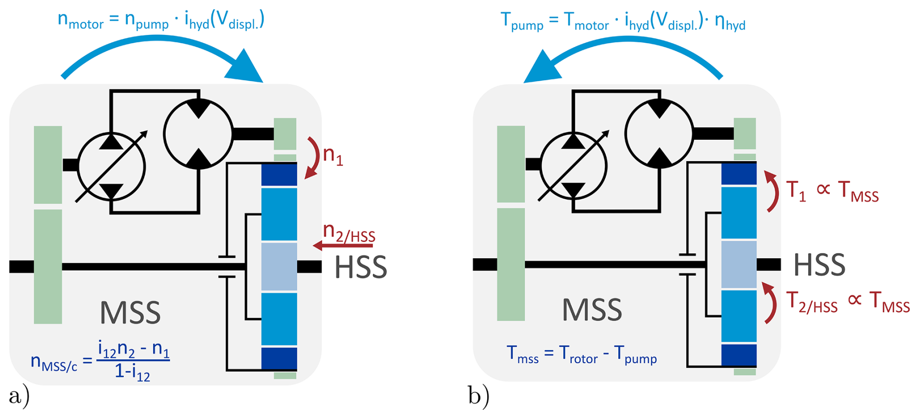
Figure 5Control direction (not direction of action) of speeds (a) and torque (b) in the drivetrain. MSS: medium-speed shaft, HSS: high-speed shaft.
Figure 5 shows how rotational speed and torque are demanded throughout the system. The planetary stage allows controlling the MSS speed by varying ring gear and generator speed (which is fixed here). Influencing MSS speed also influences the pump input speed, but with the TSR-optimal speed set point, the MSS speed and thereby pump speed are in a predefined range. Torque is given by the quotient of rotor power and rotor speed according to the standard mechanical power equation:
The drivetrain must counteract a corresponding torque, otherwise the drivetrain speed would change. Figure 5b shows how this torque demand is distributed through the planetary stage and fed back to the MSS shaft via the hydraulic system, reducing the input torque Tc corresponding to Eq. (9).
Therefore the hydraulic controller has to be able to manage this loop and additionally the strongly nonlinear behavior of the loss-prone hydraulic circuit, which makes designing such a controller challenging. More information regarding control and control challenges in power-split drivetrains can be found in Chen et al. (2019), Rossi et al. (2010), and Ibrahim et al. (2020).
As shown in Figs. 3 and 9, the maximum hydraulic power depends on both the extraction side and the choice of direct transmission. In this work, two extraction sides are defined and analyzed, and the direct transmission ratio is varied for each configuration to assess its influence on the design power. Additionally, other arrangements and variations are also discussed.
4.1 Power extraction
Varying the side of power extraction (see Fig. 1) results in two distinct power flows and control strategies. Since most commercially available hydraulic machines are generally designed for higher rotational speeds, the last planetary stage of the drivetrain is chosen as the summation stage because the torque level there is comparatively low and the rotational speed is high. The resulting power flows for both rotor- and generator-side power-split concepts are illustrated in Fig. 6.
For rotor-side power extraction, the pump speed is directly proportional to the rotor speed. As previously mentioned, this presents challenges in terms of control, since the target variable is the rotor speed itself. It is directly influenced by the torque drawn from the rotor shaft by the pump and the control loop, as well as by the reduced torque at the planetary carrier of the summation stage. This leads to reduced torque inputs for the summation stage under partial load, which could allow for minor material savings. However, depending on the direct transmission, the mechanical drivetrain must be capable of transmitting the full power when the hydraulic path is inactive, rendering these savings insignificant.
In contrast, generator-side power extraction requires the full turbine power to be transmitted through the final planetary stage all the time, as there is no power take-off in the drivetrain before. The power drawn from the generator shaft is then superimposed at this stage, leading to significantly higher loads compared to a standard planetary stage in a conventional drivetrain. However, control is simplified in this case, as the pump speed is fixed by the directly grid-coupled generator and thus does not interfere with rotor speed regulation. When considering the hydraulic power in the partial load range near cut-in, it is noticeable that the required hydraulic power exceeds the available rotor power. This effect occurs because the full rotor torque is always applied at the summation stage, which is increased compared to the rotor-side power split. The significance of this increased power becomes even more apparent with losses in the hydraulic path and is discussed later in Sect. 5.1.
4.2 Direct transmission
The power flow also depends on the direct transmission (DT), which has a significant impact on the power curve and the maximum power of the hydraulic drivetrain. As described before, the direct transmission represents the design transmission ratio and defines an operating point at which the rotor speed is directly proportional to the fixed generator speed without any hydraulic interaction. At this operating point, the hydraulic circuit does not transmit power and exhibits no rotational speed, but it must withstand a torque that is induced into the hydraulic system.
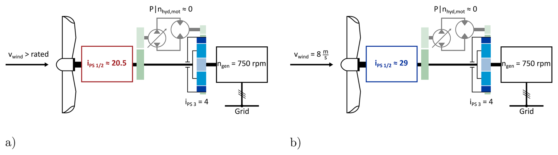
Figure 7Schematic comparison of direct transmissions (a) at rated wind speed (11.4 m s−1) with a transmission ratio of and (b) at 8 m s−1 with a transmission ratio of . The hydraulic circuit is presented as faded to imply that no power is transferred via this path.
Figure 7 illustrates two cases with different direct transmissions. Due to TSR control, each direct transmission can be associated with a corresponding wind speed, such that the direct transmission is directly linked to a proportional wind speed. For wind speeds above the rated value, the rotor speed is regulated and kept constant by the pitch controller so that the direct transmission ratio cannot exceed the ideal transmission ratio at rated wind speed. In both cases, the hydraulic system does not need to transmit power at the direct transmission operating point, as illustrated in Fig. 8. The figure shows the rotational speed of the hydraulic motor at the ring gear as a function of wind speed for two different direct transmissions. It can be observed that the zero crossing occurs at the respective direct-transmission wind speed.
When the direct transmission is designed for rated conditions, the operating range in which the hydraulic power is zero extends up to cut-out, which is advantageous. In this range, the entire power is transmitted mechanically, resulting in a maximum drivetrain efficiency at the direct-transmission wind speed. This highlights that the overall drivetrain efficiency depends on the site conditions, as they determine how much energy must be transmitted hydraulically.
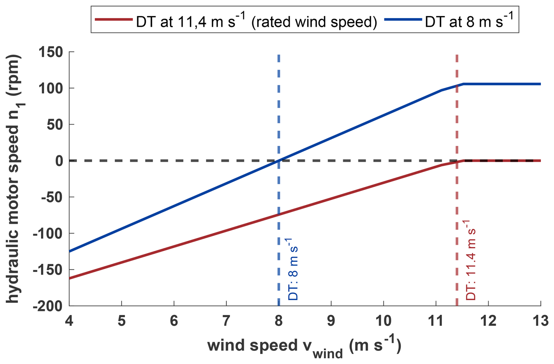
Figure 8Comparison of hydraulic motor/ring gear speeds for direct transmissions at 8 m s−1 wind speed and direct transmission > rated wind speed. The sign indicates the direction of rotational speed.
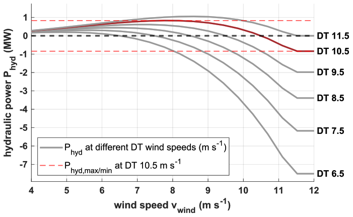
Figure 9Comparison of hydraulic power curves at different direct transmissions (DTs) with rotor-side power-split.
4.3 Minimizing the designed hydraulic power
The maximum required hydraulic power depends on both the extraction side and the direct transmission. This section aims to identify an optimum that minimizes the hydraulic power demand. It is desirable to reduce the maximum design power of the hydraulic drivetrain, enabling the use of smaller and lighter hydraulic components or maybe even cost-effective standard hydraulic units, which are currently only available for rather small power ratings in the context of wind turbine applications.
Figure 9 presents a family of curves for the rotor-side power-split with varying direct transmissions. It can be observed that the positive maximum power decreases with lower direct transmission ratios, as intended. However, the maximum power simultaneously increases sharply in the negative range, which is undesirable. Furthermore, a zero crossing occurs, indicating a reversal of the rotational direction, as visible in Fig. 8. The hydraulic circuit is therefore designed as a closed-loop system, which enables such directional changes.
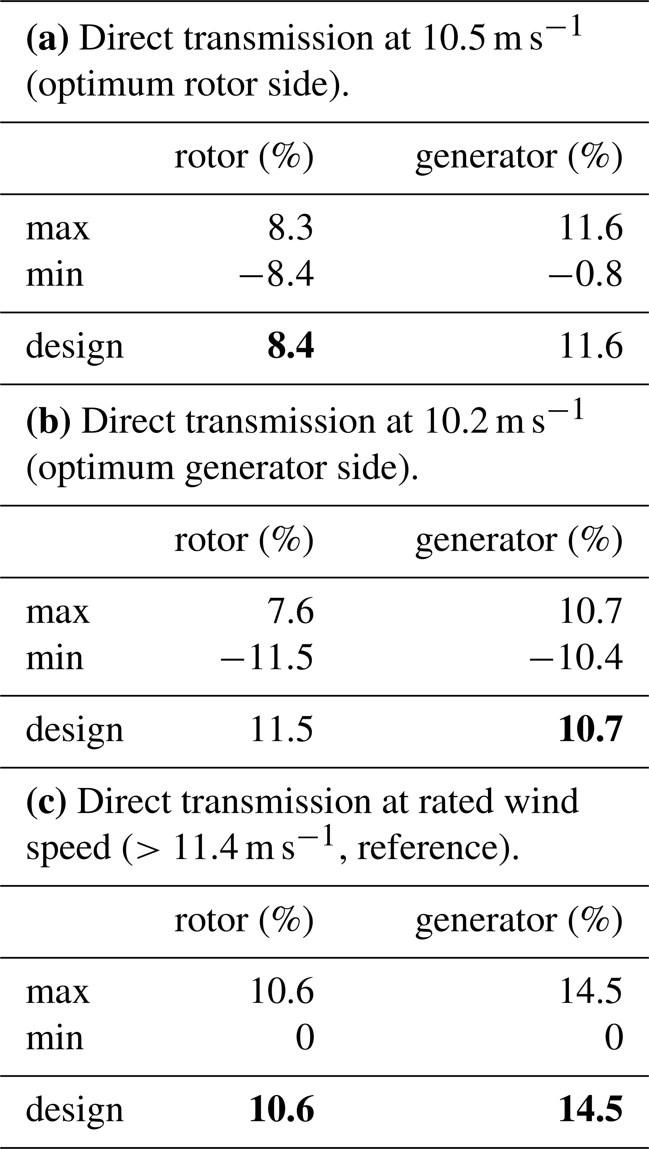
An optimum can now be determined for both power extraction sides, in which the absolute maximum hydraulic power is minimized. To do this, the transmission ratio is sought at which the positive and negative maxima have the same value. This optimum occurs for a direct transmission corresponding to a wind speed of 10.5 m s−1, where the maximum hydraulic power reaches 8.4 % of the rated power in both the negative and the positive directions for the rotor-side power-split. A similar optimum can be identified for the generator-side power-split, as shown in Table 4.
Table 4Minimum and maximum hydraulic power relative to rated power at optimal direct transmission on the rotor-side (10.5 m s−1) and generator-side (10.2 m s−1) power-split with resulting design power. Bold values indicate the optimal transmission layout at the respective wind speed.
4.4 Minimizing the hydraulic energy share
In addition to downsizing the hydraulic components, another key aspect in optimizing the drivetrain design is the influence of the direct transmission on drivetrain efficiency. Once a direct transmission is set, the hydraulic power depends on the prevailing wind speed. Since hydraulic efficiencies are generally lower than mechanical efficiencies, the overall drivetrain efficiency is largely governed by the hydraulic power curve. This results in reduced total efficiencies when hydraulic power is high and improved efficiencies when it is low. Consequently, the selection of the direct transmission must also be guided by the objective of maximizing overall drivetrain efficiency. To achieve this, site-specific wind speed distributions need to be considered in order to estimate the share of energy that must be transferred through the hydraulic system.
These comparisons are made without an actual loss model of the drivetrain in order to prevent bias resulting from poor hydraulic design, since hydraulic efficiency is strongly influenced by various parameters such as working pressure, displacement volume, and the rotation speed of the hydraulic components. There are also many possible variations in the hydraulic design, such as changing the number of pumps and motors, part-load deactivation, and different power take-off points, among others, which can improve hydraulic efficiency. It is impossible to create a hydraulic system capable of delivering high efficiencies in every direct-transmission design. While this simplification allows for a comparison of different drivetrain designs, it does not allow for a comparison to a standard turbine's energy production. Therefore, the calculated hydraulic energy shares are the theoretical minimum. An additional loss model would require a higher hydraulic energy share, which also depends on wind speed, as described in the next section.
When the direct transmission is designed for the rated wind speed, the hydraulic power reaches its maximum at 8.5 m s−1, while the minimum remains zero for all wind speeds exceeding rated wind speed. Since most sites have mean wind speeds well below the rated value of 11.4 m s−1 (DTU 10 MW), which is typically around 5–7 m s−1 for onshore sites (Hau and Siegfriedsen, 2025), the turbine will predominantly operate in a region of comparatively high hydraulic power (see Fig. 9). This results in a higher hydraulic share in the annual energy production. Positioning the direct transmission – corresponding to the zero crossing of hydraulic power – closer to the site-specific mean wind speed therefore appears beneficial to maximize overall efficiency.
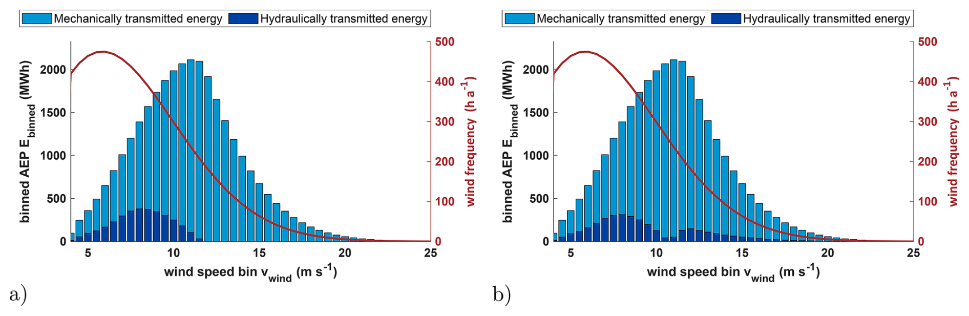
Figure 10The Rayleigh cumulative distribution function and energy bins at a mean wind speed of 7 m s−1 with a rotor-side power-split (lossless). (a) Direct transmission at rated wind speed (11.4 m s−1). (b) Direct transmission at 10.5 m s−1.
The annual energy production (AEP) is used to compare different direct transmissions and power extraction sides. It is estimated using the Rayleigh cumulative distribution function (CDF) according to DIN IEC 61400-12-1 (German Institute for Standardization, 2025) for average annual wind speeds ranging from 4 to 11 m s−1. Figure 10 illustrates the Rayleigh distribution for a mean wind speed of 7 m s−1 together with the annual energy production for each wind speed bin. Each bar is split into the hydraulic and mechanical energy share, showcasing a local minimum of the hydraulic energy share around the direct-transmission wind speed. When the direct transmission is defined at rated wind speed, the hydraulic share becomes zero above rated wind speed, whereas the hydraulic energy at a different direct transmission only becomes zero at a specific wind speed. For the comparison of different direct transmissions, the transmitted hydraulic energy is aggregated over all wind speed bins and subsequently evaluated, as shown in Fig. 11.
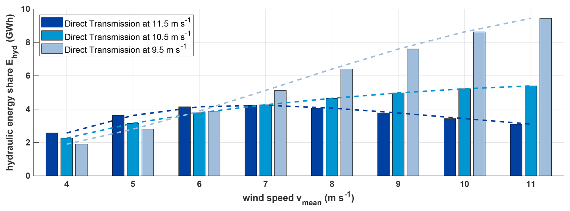
Figure 11Comparison of annual hydraulic transmitted energy for different average wind speeds at different direct transmissions – rotor side (lossless).
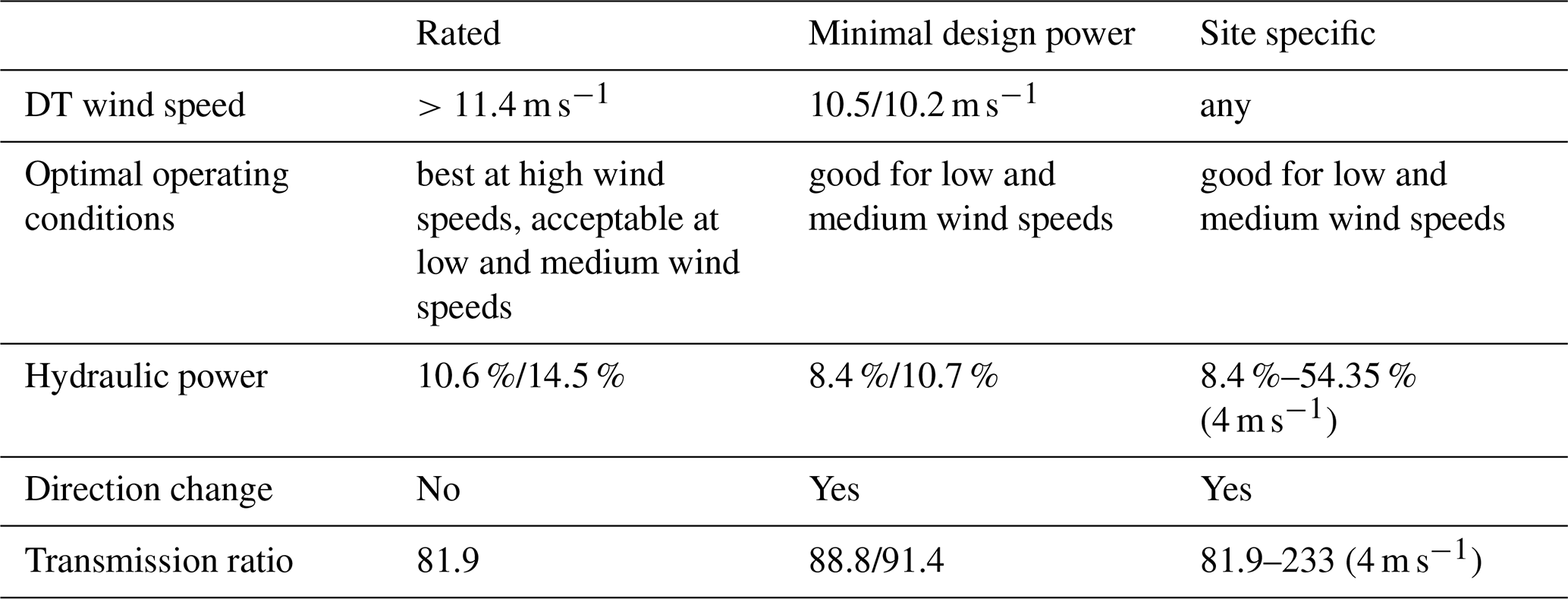
For a mean wind speed of 7 m s−1, the hydraulic share reaches its minimum at a direct transmission corresponding to a wind speed of 10.5 m s−1, which coincides with the previously identified minimum hydraulic design power for this extraction side. A direct transmission at rated conditions results in only 2 % higher values compared to 10.5 m s−1 and can therefore also be considered a valid option. Examining different mean wind speeds shows that lower direct transmissions perform best under low-wind conditions but increase substantially with higher mean wind speeds. In contrast, a direct transmission at rated conditions performs slightly worse at very low wind speeds, similarly at medium wind speeds, and best under high-wind conditions, making it a reasonable compromise to avoid site-specific drivetrain designs. Table 5 summarizes the three feasible options.
Table 5Overview of possible design options (rotor-side/generator-side power-split).
The MATLAB/Simscape model (see Sect. 3.1) is used to calculate the power losses and efficiencies of the individual variants. It is assumed that the gearbox, generator, frequency converter, and hydraulic system dominate the drivetrain efficiency. Consequently, only these components are considered loss prone. It is assumed that the mechanical part of the hydromechanical drivetrain has the same constant efficiency of 0.94 as the 10 MW DTU RWT (Bak et al., 2013). This assumption allows for a better comparison and shows whether the added hydraulic losses can be lower than the losses from the missing frequency converter.
5.1 Hydraulic efficiencies
The efficiency of the hydraulic system depends on multiple factors, including the rotational speed of the pump/motor, pressure, temperature, and for adjustable units, the displacement setting (Watter, 2022; Will et al., 2007). Given the limited publicly available data covering all dependencies and to keep the overall model tractable, the hydraulic efficiency is parameterized as a function of rotational speed, pressure, and displacement setting only. As a basis for the efficiency map in Fig. 12, data representative of an adjustable standard swash-plate axial piston unit (Parker Gold Cup P14) are used to interpolate an efficiency map at different pressure levels.
The hydraulic power curve with losses reveals a significant dependence of efficiency on wind speed (see Fig. 13). Efficiency is low at low wind speeds because hydraulic pressure in the system is low due to small rotor torques. With rotor-side power take-off in particular, efficiency drops significantly as the pump rotational speed follows the rotor speed. This starts with low pressure, low rotational speed, and high displacement volume, leading to very low efficiencies (∼0.2) at low rotor speeds. With generator-side power take-off, efficiencies are generally higher due to constant high pump speeds at the generator shaft. However, pump input power and demanded motor power rise above rotor power at low wind speeds, as described in Sect. 4.1. This leads to unrealistic conditions, and it is unclear how the drivetrain would behave in this area.
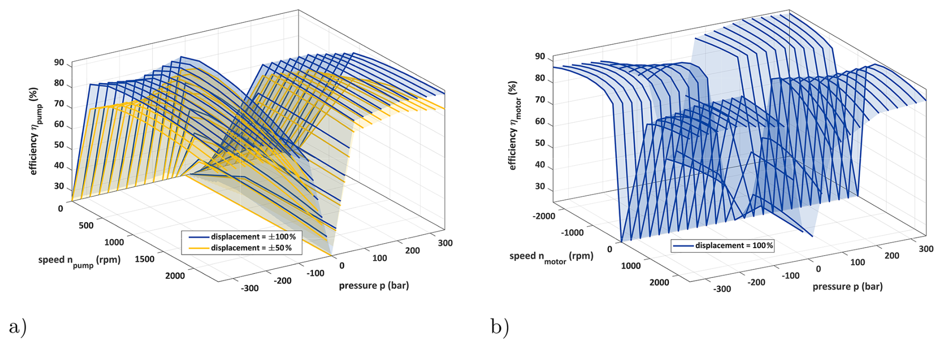
Figure 12Efficiency maps of the Parker P14 Gold Cup interpolated from efficiency curves at different pressure levels. (a) Hydraulic pump. (b) Hydraulic motor. The pump and motor are designed for four-quadrant operation. For the pump, the quadrants are defined by the sign of pressure and displacement, whereas for the motor they are defined by the sign of pressure and rotational speed.
Looking at the fixed torque ratio at the planetary stage (Eq. 4), the maximum torque at the pump is given by the transmission ratio of the planetary stage and is significantly lower than the demanded torque at the ring gear. With this low torque and the needed high rotation speeds at the generator, it is not possible to achieve the necessary power at the pump without the generator acting as a motor and adding power. When there is not enough torque applied at the ring gear, the system will reach a state of equilibrium with the rotation speeds, and the rotor speed will differ significantly from the optimal TSR speed.
This leads to the assumption that generator-side power-split is unsuitable for low wind speeds and therefore in general not practically applicable for the investigated arrangement. Thus it is excluded from further investigations in this work.
In Fig. 13b the intersection point of pump power and rotor power marks the start of the permissible operating range. Increasing partial load efficiencies would shift the intersection point of pump and rotor power towards lower wind speeds and therefore allow operation in that range of wind speeds. A possible solution could be lowering the generator speed and the transmission ratio of the last stage or interchange the positions of the motor and generator to get a different power flow.
This problem does not arise with rotor-side power-split because the input torque of the summation stage is reduced by the pump torque, which is extracted before, leading to a reduced ring gear torque. When the pump torque rises, the available rotor torque falls and with that the demanded torque of the ring gear to the motor. The worst-case scenario would be 100 % loss when hydraulic torque approaches zero. Operating the turbine in this scenario would make no sense, which is why the specific operational zone must be excluded.
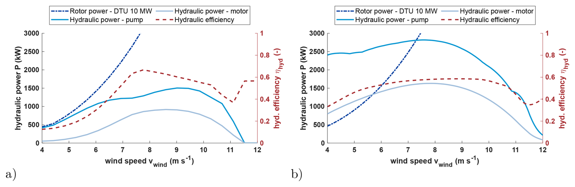
Figure 13Power curve of hydraulic components as well as rotor and hydraulic efficiency curve in partial load for rotor-side (a) and generator-side (b) power-split for direct transmission at rated wind speed. Panel (a) shows that the hydraulic power is always below the rotor input power, which is not the case for (b), where the pump and motor power is significantly higher than the rotor input power at low wind speeds.
5.2 Overall efficiency
A steady-state power curve is generated using three different models. For reference, a power curve of the 10 MW DTU turbine is generated using DNV Bladed and is used to verify the simple 10 MW standard drivetrain model, which was created to be as similar as possible in MATLAB/Simscape. This will serve as the baseline for comparison with the hydromechanical drivetrain, precluding any MATLAB-specific effects.
The most interesting aspect for evaluating drivetrain efficiency is the combination of the mechanical and hydraulic paths. While most of the power is transferred by the mechanical path with good efficiency, some of it has to be transferred by the less efficient hydraulic path. The ratio of hydraulic to mechanical power changes depending on wind speed and hydraulic efficiency. This results in a noticeable efficiency profile, with low efficiency at lower wind speeds that quickly rises above 80 % up from 7.5 m s−1 upwards. Peak efficiency is reached at the rated wind speed because the hydraulic power approaches zero, meaning that the overall efficiency is dominated by mechanical efficiency (see Fig. 14).
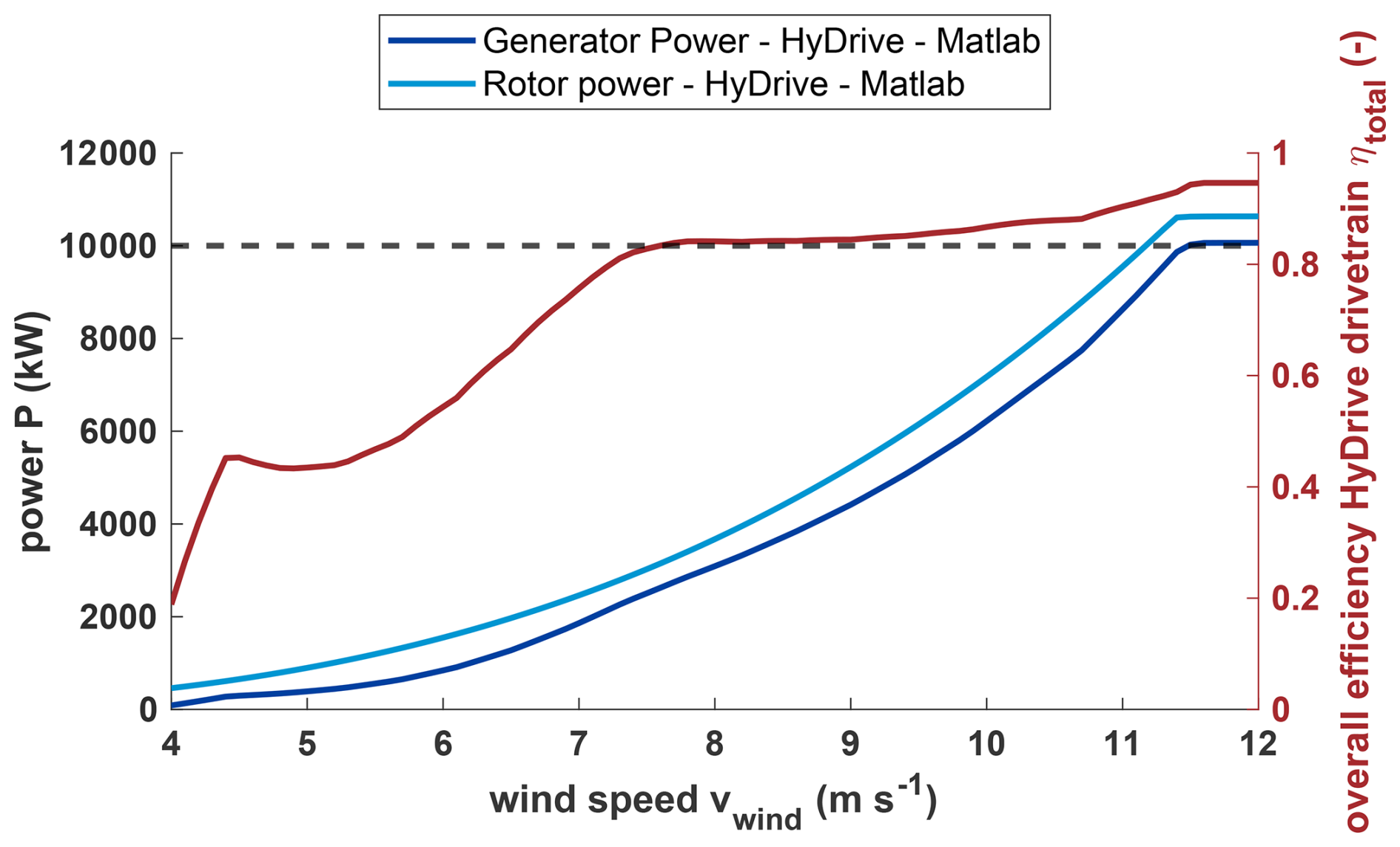
Figure 14Steady power curve of the HyDrive drivetrain and overall efficiency in partial load with direct transmission at rated wind speed (11.4 m s−1) and rotor-side power-split.
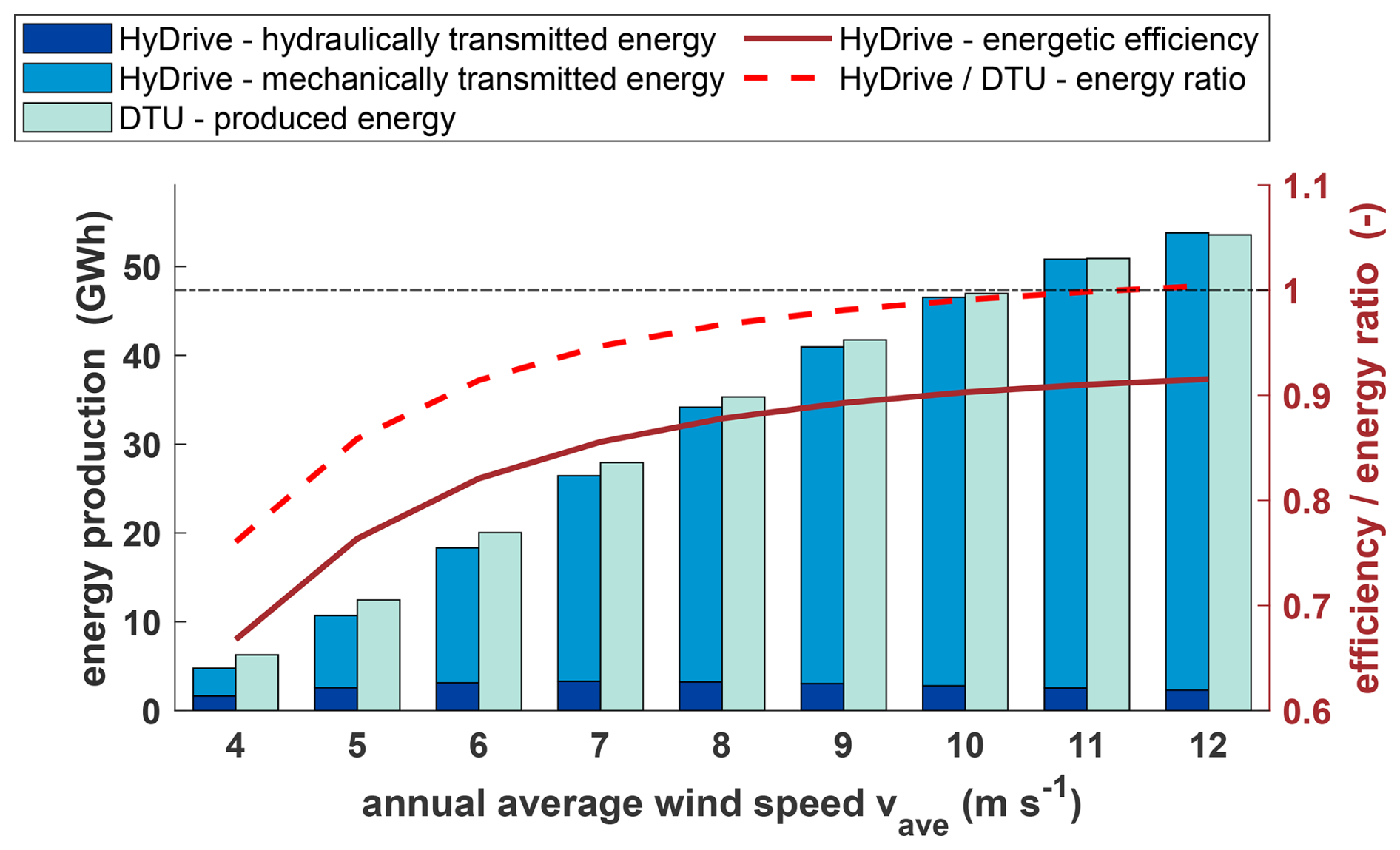
Figure 15Comparison of AEP estimation between the standard DTU 10 MW turbine and HyDrive drivetrain. Energetic efficiency of the HyDrive drivetrain (red) and relative energy ratio (red dashed) between HyDrive and the DTU turbine. Direct transmission at rated wind speed and rotor-side power-split.
The efficiency of standard drivetrains also varies slightly with power and, therefore, wind speed. However, as the varying efficiencies are determined by the generator and transmission, which are assumed to be identical in the hydromechanical drivetrain, the variation can be neglected. With this setup, a mean partial load efficiency of 71 %, a full load efficiency of 94 %, and a mean overall efficiency of 86 % are achieved. However, the low partial load efficiency in particular must be put into perspective, as the absolute losses at low wind speeds are also low. For this reason, the expected AEP is calculated for different average annual wind speeds, which can be used to calculate and compare energetic efficiency. As expected, the energetic efficiency increases with higher average annual wind speeds and approaches the maximum efficiency of 0.94, which would be the efficiency without hydraulic share. Compared to the standard DTU system, the efficiency is significantly lower despite the fact that the frequency converter efficiency is included in the calculation and only reaches a similar level at an average annual wind speed of 10 m s−1 (see Fig. 15). Such high wind speeds are very atypical for onshore locations, where wind speeds in the range of 5–7 m s−1 are more common. If the average annual wind speed is significantly higher than the rated wind speed, the hydromechanical drivetrain can even outperform the standard drivetrain, as little or no power needs to be transmitted by the hydraulics in many operating ranges.
6.1 Grid stability
A possible advantage of directly grid-coupled drivetrains is the ability to support the grid with rotational inertia. In the event of a short-term grid disturbance or brief loss of grid connection, the wind turbine can contribute to grid support (as long as electrical coupling is maintained). At present, wind turbines are often disconnected from the grid when the frequency deviates too far from the nominal frequency. Typically, modern wind turbines employ frequency converters with grid-supporting capabilities, which will need to be further improved in the future as the share of renewable energy sources in the grid continues to increase. Current research shows that this could also be achieved with new control algorithms, without actually bringing physical rotational inertia to the grid. A black start, i.e., restarting and re-energizing the grid after a total blackout, is also intended to become possible in this way (Fernández-Bustamante et al., 2021; Jain et al., 2020). Thus, the provision of physical rotational inertia is not an absolute unique selling point of hydrostatic and power-split drivetrains, but it can be implemented with less control effort. However, the power supply of the hydraulic control system must also be considered, since otherwise the wind turbine can no longer be correctly speed controlled in the event of a grid outage. Further investigations are necessary to determine the actual grid support potential of hydromechanical power-split drivetrains.
6.2 Failure rates
One of the main motivations for switching to (partially) hydraulic drivetrains is the potentially increased reliability of such a system compared to a drivetrain with a full converter. Frequency converters would no longer be needed in the HyDrive drivetrain, thereby eliminating their susceptibility to faults. Frequency converters are among the most fault-prone components of a wind turbine, with 0.45–1 faults per turbine per year (Anderson et al., 2023; Pelka and Fischer, 2023). Hydraulic pitch systems are slightly less prone to failure, with 0.54 faults per turbine per year. They also do not require as much downtime and need less repair work than replacing a converter (Walgern et al., 2023). However, due to their relatively low dynamics compared to drivetrain hydraulics, they are not easily comparable. Due to the lack of turbines with this technology, failure probabilities for hydraulic drivetrains cannot be found. However, hydraulic drivetrains are used in many commercial vehicles as drive systems with similar dynamic requirements, albeit with significantly lower rated power. In these applications, reliability depends primarily on good system design but also on extensive maintenance to achieve very low failure rates (Jocanović et al., 2012). This demonstrates the relevance of detailed and comprehensive design and conceptualization of such a partially hydraulic drivetrain.
6.3 Hydraulic fluids
Mineral oil-based hydraulic fluids are particularly suitable for transmitting high power in stationary systems, operating conditions that are also present in the HyDrive drivetrain. Despite the steady growth in biologically rapidly degradable alternatives, these fluids are still used in the vast majority of hydraulic applications, and most manufacturers develop their products primarily for using them. With an annual wind turbine operating time of approximately 6500 h at an average 7 m s−1 site and a recommended oil change interval of approximately 5000 operating hours, a complete replacement of the hydraulic fluid would be necessary at least once a year. This period can be significantly extended with appropriate condition monitoring (Bauer and Niebergall, 2020). For a wind turbine in the 10 MW power class, the volume of hydraulic fluid to be replaced can be estimated to be approximately of the same order of magnitude as the gearbox oil volume of a conventional drivetrain, exceeding an amount of 2000 L (MHI Vestas Offshore Wind A/S, 2025).
Since wind turbines are located directly in rural areas in the case of onshore sites and directly above aquatic ecosystems in the case of offshore sites, there is a particularly high risk of environmental damage in the event of a leak, especially when mineral-oil-based hydraulic fluids are used. However, this risk can be countered with appropriate technical measures. Hydraulic assemblies are typically designed as sealed units and are furthermore isolated by surrounding wind turbine structures, such as the nacelle (drivetrain) or the rotor hub and blades (pitch systems). This ensures that an unintended release of hydraulic fluid into the environment can be largely prevented. The fire risk associated with leakages can be reduced by using hydraulic oils with the highest possible flash point.
Hydromechanical drivetrains can be designed in different configurations, each with different characteristics. To keep the number of variations manageable, two different output sides (rotor- and generator-side power-split) and different direct transmissions were compared. The design has two objectives. Firstly, the design power of the hydraulic part should be kept as small and straightforward as possible so that the system can be lightweight and inexpensive. Secondly, the amount of energy transmitted hydraulically should be minimized in order to maximize the efficiency of the overall drivetrain.
High design power of the hydraulic path results in high weight and costs due to multiple or larger hydraulic components. However, a small design power does not guarantee a minimized hydraulically transmitted energy. High absolute hydraulic power in frequently occurring wind speed ranges should be avoided, which leads to a dependency of the turbine design on the site conditions of the wind turbine. By designing different direct transmissions, both the maximum hydraulic power and the minimized hydraulically transmitted energy can be varied. The direct transmission structurally determines one operating point at which the hydraulic share becomes zero. Direct transmissions at low wind speeds prove to be fundamentally unsuitable in this context, as the design power becomes too high (in some cases higher than the rated power of the wind turbine). This results in one optimal direct transmission for both the rotor-side and the generator-side power-split, in which the design power is minimal. Depending on the average annual wind speed and considering its frequency distribution over the year, an energy analysis shows that direct transmissions close to rated power perform well for most realistic wind conditions, while a site-specific design has only a minor benefit, which is likely to be offset by the additional costs for site-specific designs. In addition, the overall gear ratio of the transmission increases with direct transmissions at lower wind speeds. It has been shown that a higher hydraulic power is generally required when power is split from the generator side and that this power exceeds the input power close to cut-in wind speed, which makes drawing power from the generator-side unattractive.
When using an efficiency map for the hydraulic components, the hydraulics show an efficiency that is highly dependent on wind speed. The design of the hydraulic system is complex, and many parameters must be taken into account, which means that the efficiency assumed here, which is rather conservative, can be increased even further by specifically optimizing a specific direct transmission. Operation at the outer limits of the operating range of the hydraulic components (low speed, torque, or displacement volume) causes the efficiency to drop rapidly. This can possibly be improved by better scaling of the components to the required operating range. The use of an adjustable motor could reduce the relatively large operational range of the pump and therefore usage in the peripheral zones. When using multiple hydraulic machines, there is an additional option to deactivate whole units in partial load to further improve efficiency in this area as suggested in Schmitz (2015). Another option is using hydraulic machines with higher individual efficiency, such as bent-axis axial piston pumps.
Despite the partially low hydraulic efficiency, the overall drivetrain efficiency remains competitive, particularly when wind speeds close to the cut-in threshold are infrequent. Additionally, the relatively low efficiency close to cut-in wind speed is not significant due to the low absolute power in this range, which is offset by the increased efficiency in the full load range compared to the standard system. For sites with an average annual wind speed of about 10 m s−1, the energy production of the hydromechanical drivetrain in direct transmission can match that of the standard drivetrain, and from about 12 m s−1 it can even exceed it. At lower average wind speeds, the hydromechanical drivetrain is a few percent less efficient than the standard system. However, it is questionable whether the hydromechanical drivetrain provides sufficient additional benefits to justify a reduction in yield. For low wind speeds and the generator-side power-split, it was shown that the rotor power is insufficient to operate the turbine in a desired manner. To circumvent this problem, lowering the generator speed or raising the cut-in speed can be considered. The cut-in speed is typically increased in many systems, including the 10 MW DTU turbine, in order to avoid vibration problems, which was neglected in this work to incorporate TSR control across the entire partial load range.
In order to further increase the efficiency of the system, additional design variants of the drivetrain and hydraulics must be investigated and simulated. Possible options include power take-off at the rotor shaft with a slow-rotating radial piston pump; reduction of the generator speed; variation of the fixed gear ratio; or variation of the pump/motor types, number, and arrangement. A large number of design parameters influence the efficiency and control strategies of the drivetrain, requiring a more extensive investigation in order to identify the best possible variant. In addition, dynamic load cases must be investigated and simulated, paying attention to issues such as grid compatibility and behavior in the event of a grid failure. The hypothesis that such a system, which is directly connected to the grid, exhibits grid-supporting behavior must be verified. It is also difficult to estimate the extent to which hydraulics can increase the reliability of the system. Although frequency converters are sensitive to failure, hydraulic systems are maintenance-intensive and require large quantities of hydraulic oil, which must be contained and protected against leakage in the nacelle under high pressures.
The concept of the hydromechanical power-split drivetrain shows some potential strengths that require further research but also many challenges that do not arise with conventional systems and therefore do not represent sufficient competition at the current stage of development. For many issues, it would be useful to develop a test bench model, as Chen et al. (2019) had already begun, to get a better understanding of how the power flow and efficiency behave in peripheral areas. In addition, an aeroelastic simulation tool must be used to simulate the hydromechanical drivetrain for dynamic load cases and behavior in the event of grid failures.
| AEP | Annual energy production |
| CDF | Cumulative distribution function |
| CVT | Continuously variable transmission |
| DT | Direct transmission |
| DTU | Technical University of Denmark |
| HSS | High-speed shaft |
| MSS | Medium-speed shaft |
| RWT | Reference wind turbine |
| TRL | Technology readiness level |
| TSR | Tip-speed ratio |
| WTG | Wind turbine generator |
All necessary research data have been included in the paper. For further information please contact the authors.
PS created the drivetrain calculation and simulation models, carried out and evaluated simulations, and planned and wrote most parts of the paper. JS created the hydraulic model with efficiency maps and created the mechanical design and also wrote and reworked parts of the paper. SSt and PD supervised and acquired project funding, contributed literature research, and supplementary Bladed simulations and concept ideas. AD contributed to first considerations. All co-authors contributed with several discussions and thoroughly reviewed the paper.
The contact author has declared that none of the authors has any competing interests.
Publisher's note: Copernicus Publications remains neutral with regard to jurisdictional claims made in the text, published maps, institutional affiliations, or any other geographical representation in this paper. The authors bear the ultimate responsibility for providing appropriate place names. Views expressed in the text are those of the authors and do not necessarily reflect the views of the publisher.
The authors thank Stabo GmbH for supporting and accompanying the project as an industrial partner.
The authors thank Torsten Petersen, who initiated the project in a private capacity and brought the consortium together. The present work is based on his fundamental considerations, which were first documented in patent no. DE 10 2009 034 116 A1.
The authors thank Maximilian Barg for his contributions during the initial phase of the project.
AI-based tools (GPT 5 and DeepL) were used to assist with translation and language editing of this paper.
This work was funded by the German Federal Ministry for Economic Affairs and Energy (BMWE) within the framework of the ZIM (Central Innovation Programme for SMEs) research and development project HyDrive Wind – Development of a continuously variable wind turbine gearbox with power-split and hydraulic share (ref. no. KK5410407RF3). We acknowledge support for the article processing charge by the Open Access Publication Fund of Hamburg University of Applied Sciences.
This paper was edited by Yi Guo and reviewed by two anonymous referees.
Anderson, F., Dawid, R., McMillan, D., and Cava, D. G.: On the Sensitivity of Wind Turbine Failure Rate Estimates to Failure Definitions, J. Phys. Conf. Ser., 2626, 012025, https://doi.org/10.1088/1742-6596/2626/1/012025, 2023. a
Bak, C., Zahle, F., Bitsche, R., Kim, T., Yde, A., C. Henriksen, L., Natarajan, A., and Hansen, M.: Description of the DTU 10 MW Reference Wind Turbine, DTU, technical report, 2013. a, b, c, d
Basteck, D. A. and Voith Turbo Wind GmbH & Co. KG: Elektromechanischer Hochleistungsantrieb für Windenergieanlagen der Multi-Megawatt-Klasse, Abschlussbericht des Bundesministeriums für Umwelt, Naturschutz und Reaktorsicherheit der Bundesrepublik Deutschland, https://edocs.tib.eu/files/e01fb08/58525236X.pdf (last access: 11 May 2026), 2008. a, b
Bauer, G. and Niebergall, M.: Ölhydraulik: Grundlagen, Bauelemente, Anwendungen, Springer Fachmedien, Wiesbaden, ISBN 978-3-658-27026-1, 978-3-658-27027-8, https://doi.org/10.1007/978-3-658-27027-8, 2020. a
Bottiglione, F., Mantriota, G., and Valle, M.: Power-Split Hydrostatic Transmissions for Wind Energy Systems, Energies, 11, 3369, https://doi.org/10.3390/en11123369, 2018. a, b
Chen, W., Lin, Y., Li, W., Liu, H., Tu, L., and Meng, H.: Study on speed and torque control of a novel hydromechanical hybrid transmission system in wind turbine, IET Renewable Power Generation, 13, 1554–1564, https://doi.org/10.1049/iet-rpg.2018.6105, 2019. a, b, c, d, e, f
Chen, W., Wang, X., Zhang, F., Liu, H., and Lin, Y.: Review of the application of hydraulic technology in wind turbine, Wind Energy, 23, 1495–1522, https://doi.org/10.1002/we.2506, 2020. a, b, c, d, e, f
Diepeveen, N., Mulder, S., and van der Tempel, J.: Field tests of the DOT500 prototype hydraulic wind turbine, RWTH Aachen, https://publications.rwth-aachen.de/record/724077/files/724077.pdf (last access: 11 May 2026), 2018. a
Dziuba, P. F. and Honzek, R.: New Continuous Variable Power-Split Tractor Transmission, 19–27, University of Hohenheim, https://hohpublica.uni-hohenheim.de/server/api/core/bitstreams/37982faa-4a8a-4f1c-b8e1-069debb51554/content (last access: 11 May 2026), 1997. a
Fernández-Bustamante, P., Barambones, O., Calvo, I., Napole, C., and Derbeli, M.: Provision of Frequency Response from Wind Farms: A Review, Energies, 14, 6689, https://doi.org/10.3390/en14206689, 2021. a
German Institute for Standardization: DIN EN IEC 61400-12-1 (VDE 0127-12-1): 2025-01, Deutsche Kommission Elektrotechnik, Elektronik, Informationstechnik, 2025. a
Hansen, M. H. and Henriksen, L. C.: Basic DTU Wind Energy controller, Report, DTU Wind Energy, Technical University of Denmark, https://backend.orbit.dtu.dk/ws/portalfiles/portal/56263924/DTU_Wind_Energy_E_0028.pdf (last access: 11 May 2026), 2013. a
Hau, E. and Siegfriedsen, S.: Wind Turbines: Fundamentals, Technologies, Application, Economics, Springer Nature Switzerland, Cham, 4th edn., ISBN 978-3-031-87795-7, 2025. a, b, c, d, e
Ibrahim, M. E., Shaltout, M. L., and Kassem, S. A.: Extremum-seeking control for energy-harvesting enhancement of wind turbines with hydromechanical drivetrains, Wind Energy, 23, 2113–2135, https://doi.org/10.1002/we.2548, 2020. a, b
Jain, A., Sakamuri, J. N., and Cutululis, N. A.: Grid-forming control strategies for black start by offshore wind power plants, Wind Energ. Sci., 5, 1297–1313, https://doi.org/10.5194/wes-5-1297-2020, 2020. a
Jocanović, M., Šević, D., Karanović, V., Beker, I., and Dudić, S.: Increased Efficiency of Hydraulic Systems Through Reliability Theory and Monitoring of System Operating Parameters, Strojniški vestnik – Journal of Mechanical Engineering, 58, 281–288, https://doi.org/10.5545/sv-jme.2011.084, 2012. a
Lin, Y., Tu, L., Liu, H., and Li, W.: Hybrid Power Transmission Technology in a Wind Turbine Generation System, IEEE/ASME T. Mech., 20, 1218–1225, https://doi.org/10.1109/TMECH.2014.2328629, 2015. a
Liu, K., Chen, W., Chen, G., Dai, D., Ai, C., Zhang, X., and Wang, X.: Application and analysis of hydraulic wind power generation technology, Energy Strateg. Rev., 48, 101117, https://doi.org/10.1016/j.esr.2023.101117, 2023. a
Liu, Q., Appunn, R., and Hameyer, K.: A Study of a Novel Wind Turbine Concept with Power Split Gearbox, Journal of International Conference on Electrical Machines and Systems, 2, https://doi.org/10.11142/jicems.2013.2.4.478, 2013. a
Liu, Q., Appunn, R., and Hameyer, K.: Wind Turbine With Mechanical Power Split Transmission to Reduce the Power Electronic Devices: An Experimental Validation, IEEE T. Ind. Electron., 64, 8811–8820, https://doi.org/10.1109/TIE.2016.2622666, 2017. a
Mahato, A. C. and Ghoshal, S. K.: Various power transmission strategies in wind turbine: an overview, International Journal of Dynamics and Control, 7, 1149–1156, https://doi.org/10.1007/s40435-019-00543-8, 2019. a, b
Mantriota, G.: Power split transmissions for wind energy systems, Mech. Mach. Theory, 117, 160–174, https://doi.org/10.1016/j.mechmachtheory.2017.07.003, 2017. a, b, c, d
Matthies, H. J. and Renius, K.-T.: Einführung in die Ölhydraulik: für Studium und Praxis: 110 Kurzaufgaben mit Lösungshinweisen, Springer eBook Collection, Springer Vieweg, Wiesbaden, 9th edn., ISBN 978-3-658-35672-9, 978-3-658-35673-6, https://doi.org/10.1007/978-3-658-35673-6, 2021. a
MHI Vestas Offshore Wind A/S: Allgemeine Beschreibung MV0W 9-MW-Plattform, https://www.uvp-verbund.de/documents-ige-ng/igc_mv/D4CA77FD-E592-4C94-BFC8-FC82F537DC5B/01. General Description_9 MW_Platform.pdf, last access: 17 December 2025. a
Müller, H. W.: Die Umlaufgetriebe: Auslegung und vielseitige Anwendungen, vol. 28 of Konstruktionsbücher, Springer Berlin Heidelberg and Imprint and Springer, Berlin, Heidelberg, 2nd edn., ISBN 978-3a-642-63698-1, 1998. a, b, c
Pelka, K. and Fischer, K.: Field-data-based reliability analysis of power converters in wind turbines: Assessing the effect of explanatory variables, Wind Energy, 26, 310–324, https://doi.org/10.1002/we.2800, 2023. a
Rampen, W.: Gearless Transmissions for Large Wind Turbines: The history and Future of Hydraulic Drives., in: DEWEK 2006, the international technical conference: 8th German Wind Energy Conference, 22 to 23 November 2006, Bremen, Deutsches Windenergie-Institut, https://www.research.ed.ac.uk/en/publications/gearless-transmissions-for-large-wind-turbines-the-history-and-fu (last access: 11 May 2026), 2007. a
Rossi, C., Corbelli, P., and Grandi, G.: Electric Driven Continuously Variable Transmission for Wind Energy Conversion System, University of Bologna, 5, 2010. a, b
Rybak, S. C.: Description of the 3 MW SWT-3 wind turbine at San Gorgonio Pass, California, https://ntrs.nasa.gov/citations/19830010987, Bendix Corp., NTRS Document ID: 19830010987, Legacy CDMS (CDMS), 1982. a
Schmitz, J. B.: Konzipierung und Vermessung hydrostatischer Windkraftgetriebe, no. 80 in Reihe Fluidtechnik D, Shaker, Aachen, ISBN 978-3-8440-3654-1, 2015. a, b, c, d
Song, Z., Weidinger, P., Zweiffel, M., Dubowik, A., Mester, C., Yogal, N., and Oliveira, R. S.: Traceable efficiency determination of a 2.75 MW nacelle on a test bench, Forschung im Ingenieurwesen, 87, 259–273, https://doi.org/10.1007/s10010-023-00650-1, 2023. a
Taherian-Fard, E., Sahebi, R., Niknam, T., Izadian, A., and Shasadeghi, M.: Wind Turbine Drivetrain Technologies, IEEE T. Ind. Appl., 56, 1729–1741, https://doi.org/10.1109/TIA.2020.2966169, 2020. a
Thomsen, K. E., Dahlhaug, O. G., Niss, M. O. K., and Haugset, S. K.: Technological Advances in Hydraulic Drive Trains for Wind Turbines, Energ. Proced., 24, 76–82, https://doi.org/10.1016/j.egypro.2012.06.089, 2012. a
Walgern, J., Fischer, K., Hentschel, P., and Kolios, A.: Reliability of electrical and hydraulic pitch systems in wind turbines based on field-data analysis, Energy Reports, 9, 3273–3281, https://doi.org/10.1016/j.egyr.2023.02.007, 2023. a
Watter, H.: Hydraulik und Pneumatik: Grundlagen und Übungen - Anwendungen und Simulation, Springer Fachmedien, Wiesbaden, ISBN 978-3-658-35865-5, 978-3-658-35866-2, https://doi.org/10.1007/978-3-658-35866-2, 2022. a
Will, D., Gebhardt, N., and Ströhl, H., eds.: Hydraulik: Grundlagen, Komponenten, Schaltungen, SpringerLink Bücher, Springer Berlin Heidelberg, Berlin, Heidelberg, 3rd edn., ISBN 978-3-540-34322-6 978-3-540-34326-4, https://doi.org/10.1007/978-3-540-34326-4, 2007. a
World Wind Energy Association: WWEA Annual Report 2023, Annual report, World Wind Energy Association, Bonn, https://wwindea.org/ss-uploads/media/2024/3/1711538106-40ab83f2-3e01-4c0a-9d28-e0a21bff72e6.pdf (last access: 11 May 2026), 2024. a
Yu, J., Cao, Z., Cheng, M., and Pan, R.: Hydro-mechanical power split transmissions: Progress evolution and future trends, P. I. Mech. Eng. D-J. Aut., 233, 727–739, https://doi.org/10.1177/0954407017749734, 2019. a
Zhang, H., Weidinger, P., Mester, C., Song, Z., Heller, M., Dubowik, A., Tegtmeier, B., and Eustorgi, K.: State-of-the-art efficiency determination of a wind turbine drivetrain on a nacelle test bench, Wind Energ. Sci., 10, 1625–1636, https://doi.org/10.5194/wes-10-1625-2025, 2025. a
- Abstract
- Introduction
- State of the art of power-split drivetrains
- Concept introduction
- Concept variations
- Drivetrain efficiency
- Grid stability, failure rates, and maintenance
- Conclusions
- Appendix A: List of abbreviations used in this paper
- Code and data availability
- Author contributions
- Competing interests
- Disclaimer
- Acknowledgements
- Financial support
- Review statement
- References