
the Creative Commons Attribution 4.0 License.
the Creative Commons Attribution 4.0 License.
 | 19 Aug 2026
Integrated control of floating offshore wind farms with reconfigurable layouts
Ryozo Nagamune
This paper proposes an integrated optimization-based control framework for floating offshore wind farms (FOWFs) with reconfigurable layouts. The framework coordinates four farm-level control strategies, that is, turbine repositioning, wake steering, power derating, and Helix wake mixing, to either (i) maximize total farm power output or (ii) track a prescribed farm-level power setpoint while mitigating wake effects. This integration is motivated by the fact that individual strategies may be effective only under specific conditions or broadly effective but not always optimal, whereas their coordinated use can deliver robust performance improvements across a broad range of operating scenarios. The framework targets FOWFs with reconfigurable layouts, where turbines are mounted on floating platforms anchored to the seabed with sufficiently long and slack mooring lines, allowing them to shift within a certain range and thereby enabling controlled positional adjustments. Given the ambient inflow conditions (wind speed and direction), the framework computes coordinated per-turbine commands, including yaw angles, derating commands that limit each turbine's power to not exceed a prescribed value, and mean-to-peak amplitude of sinusoidal blade-pitch excitation, to meet the farm power requirement and to reduce the wake overlap. Numerical simulations using the Flow Redirection and Induction in Steady State (FLORIS) engineering wake model show that the integrated method consistently outperforms any individual strategy. However, because validation in the FLORIS model remains limited for cases in which yaw-based control, including turbine repositioning and wake steering, is applied simultaneously with Helix wake mixing or power derating on the same turbine, the corresponding quantitative gains should be interpreted with caution. We therefore also considered additional restricted benchmark cases in which these control actions were not assigned together to the same turbine. These cases provide conservative lower-bound benchmarks for the integrated-control studies, while still indicating that the main qualitative benefits of the proposed framework are preserved. These findings highlight the potential of integrated control to enhance the efficiency, flexibility, and adaptability of FOWFs, offering a promising pathway to overcome the limitations and improve the performance of standalone control methods.
- Article
(5007 KB) - Full-text XML
- BibTeX
- EndNote


The global shift toward sustainable energy demands a rapid expansion of offshore wind power, which offers immense potential for large-scale clean electricity generation. By mounting turbines on buoyant platforms anchored to the seabed, floating offshore wind farms (FOWFs) extend offshore wind development into deepwater regions where fixed-bottom foundations are not feasible (Musial et al., 2022). This extension opens new geographical markets, allowing deployment in areas far from shore where winds are stronger and more consistent.
Realizing this potential, however, requires addressing aerodynamic challenges that emerge when turbines are clustered into farms. In wind farms, upstream turbines extract kinetic energy and generate wakes with reduced wind speed and elevated turbulence. When these wakes reach downstream turbines, they reduce power production and increase unsteady loading, with associated fatigue implications. In FOWFs, these consequences can be further amplified because the disturbed inflow can excite platform motions and shift turbine operating conditions (Xue et al., 2022; Carmo et al., 2024). Such wake-induced effects can reduce total farm output by up to 20 %, reducing project revenue and complicating reliable grid integration (Barthelmie et al., 2009). Mitigating wake losses is therefore critical to reducing the levelized cost of energy, ensuring stable power delivery, and meeting the ambitious offshore wind deployment targets set by many nations (Musial et al., 2022).
Wind farm control has been an active area of research for decades, aimed at mitigating wake effects and improving farm-wide performance (Boersma et al., 2017; Doekemeijer et al., 2019; Kheirabadi and Nagamune, 2019; Andersson et al., 2021; Dong et al., 2022). In FOWFs, turbine repositioning through passive force generation (Han et al., 2017; Kheirabadi and Nagamune, 2020, 2021a, b; Gao et al., 2022; Niu et al., 2023, 2024; Jard and Snaiki, 2023; Kilinc, 2022; Mahfouz and Cheng, 2023) has emerged as a particularly promising approach. In this method, floating turbines are dynamically displaced to reduce wake overlap without the need for dedicated propulsion systems or additional mechanical actuators. Specifically, the displacement is achieved by exploiting aerodynamic forces on the rotor plane, for example, through intentional yaw misalignment, to generate thrust forces in the desired direction of motion. When combined with sufficiently long and slack mooring lines, these forces induce platform drift, enabling turbines to relocate to positions more favorable for both energy production and fatigue load reduction. Notably, a nonzero yaw offset is required to be sustained to balance mooring restoring forces at the repositioned position. Sustained yaw offsets can alter both mean and cyclic component loads (e.g., blade-root bending moments and tower loads) and thus influence fatigue (Damiani et al., 2018); quantifying these fatigue implications is beyond the scope of the present study. Compared with propulsion-based repositioning methods, this passive strategy requires significantly less additional energy input and relies solely on actuators already available in modern utility-scale wind turbines, making it an attractive option for future deployment.
Despite its potential, this repositioning method has an inherent limitation: the achievable crosswind displacement depends strongly on wind direction, which affects the tensions in the mooring lines. For a symmetric three-line mooring system, when the wind direction leads to a distribution in which only one mooring line becomes predominantly load-bearing while the other two lines slacken, the platform can drift laterally with relatively little resistance, enabling substantial repositioning and corresponding performance improvements (Kheirabadi and Nagamune, 2020). By contrast, when the wind direction results in two mooring lines remaining in tension, the restoring stiffness of the mooring system rises sharply, restricting the platform's ability to move sideways. In such cases, the scope for crosswind repositioning diminishes, and the effectiveness of repositioning as a standalone strategy also becomes limited. One solution to overcome this limitation is to optimize farm layout prior to installation by carefully determining mooring line orientations across turbines so that at least a subset of turbines maintains sufficient mobility under any wind condition, as studied in Froese et al. (2022). In contrast, the present study focuses on how to overcome this limitation assuming that the farm layout is already fixed after installation.
To overcome this limitation, turbine repositioning can be integrated with other established wind farm control strategies, namely wake steering (Burton et al., 2011; Fleming et al., 2015), power derating (Steinbuch et al., 1988; Johnson and Thomas, 2009), and dynamic wake mixing (Goit and Meyers, 2015; van den Berg et al., 2024; Dammann et al., 2025; van Vondelen et al., 2025, 2026). Specifically, wake steering redirects wakes away from downstream turbines by intentionally yawing upstream turbines, thereby reducing energy losses when repositioning cannot achieve sufficient lateral offset. Power derating lowers the thrust of selected upstream turbines, weakening their wakes and alleviating downstream loading. Wake mixing enhances turbulent diffusion by promoting the entrainment of high-energy ambient flow into the wake, thereby accelerating wake recovery and improving inflow conditions for downstream turbines (van den Berg et al., 2024). Wake mixing can be implemented through blade pitch actuation and is categorized into the Pulse method (collective pitch modulation) and the Helix method (individual pitch modulation); a comparison of the resulting wake structures for both methods is provided in Fig. 2 in van den Berg et al. (2024). In this paper, “dynamic wake mixing” refers to Helix wake mixing realized via periodic individual-blade pitch excitation. Note that, in the wake-mixing studies (Goit and Meyers, 2015; van den Berg et al., 2024; Dammann et al., 2025; van Vondelen et al., 2025, 2026), wake mixing was not applied simultaneously with other strategies. Taken together, these methods mitigate wake interactions through mechanisms that do not rely on large platform displacements and therefore remain effective even when repositioning mobility is constrained.
In this study, we propose an integrated wind farm controller for FOWFs with reconfigurable layouts that unifies turbine repositioning, wake steering, power derating, and dynamic wake mixing within a single optimization framework. The controller formulates wind farm control as an optimal control problem, to be solved using available measurements of free-stream wind speed and wind direction together with a prescribed farm-level power reference from the grid. The framework is designed to operate in two distinct modes, reflecting the main requirements of wind farm operation. In power maximization mode, the objective is to maximize total farm power output, which is critical when the grid demands as much renewable power as possible. In power regulation mode, the objective is to track a prescribed wind farm power setpoint while simultaneously mitigating wake interactions, which is essential for grid stability. To achieve these objectives, the controller computes coordinated commands including the yaw angle (the angle between the incoming wind direction and the rotor axis), the maximum allowable power output for derating, and the Helix excitation amplitude (mean-to-peak individual-blade pitch modulation) for each turbine, and dispatches them to the corresponding turbine-level controllers for execution. The proposed approach is evaluated using the Flow Redirection and Induction in Steady State (FLORIS) engineering wake model (National Renewable Energy Laboratory, 2025), augmented with a steady-state turbine position solver. This study focuses on steady-state (time-averaged) farm-level aerodynamic performance; transient wake dynamics are beyond the scope of the present FLORIS-based evaluation. Simulation results across diverse wind conditions demonstrate that the integrated controller consistently outperforms any single control strategy. Nevertheless, the current FLORIS model has limited validation for operating conditions in which yaw-based control, including turbine repositioning and wake steering, is used on the same turbine together with Helix wake mixing or power derating. Accordingly, the corresponding quantitative improvements should be interpreted with appropriate caution. To further strengthen the assessment, we also introduced restricted benchmark cases in which such combinations were excluded. These benchmarks provide conservative lower bounds for the integrated-control studies and still demonstrate the main qualitative advantages of the proposed framework. These results underscore the potential of integrated control to enhance farm performance, reduce operational costs, and strengthen the economic viability of large-scale deployment of reconfigurable FOWFs.
The remainder of the paper is organized as follows. Section 2 formulates the control problem for FOWFs with reconfigurable layouts. To address this problem, Sect. 3 presents the design of the integrated FOWF controller. Section 4 then evaluates the proposed controller through numerical simulations and provides a detailed analysis of its performance. Finally, Sect. 5 summarizes the main findings and outlines future research directions.
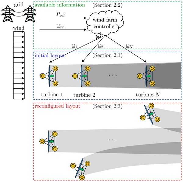
This section formulates the control problem for FOWFs with reconfigurable layouts (Sect. 2.1). Specifically, we seek to design a wind farm controller that computes coordinated control inputs for the individual turbine controllers based on available information (Sect. 2.2), in order to achieve desired control objectives (Sect. 2.3). An illustrative example of this setup is shown in Fig. 1, which depicts an example FOWF equipped with a supervisory wind farm controller. This schematic will serve as a reference throughout the formulation in this section.
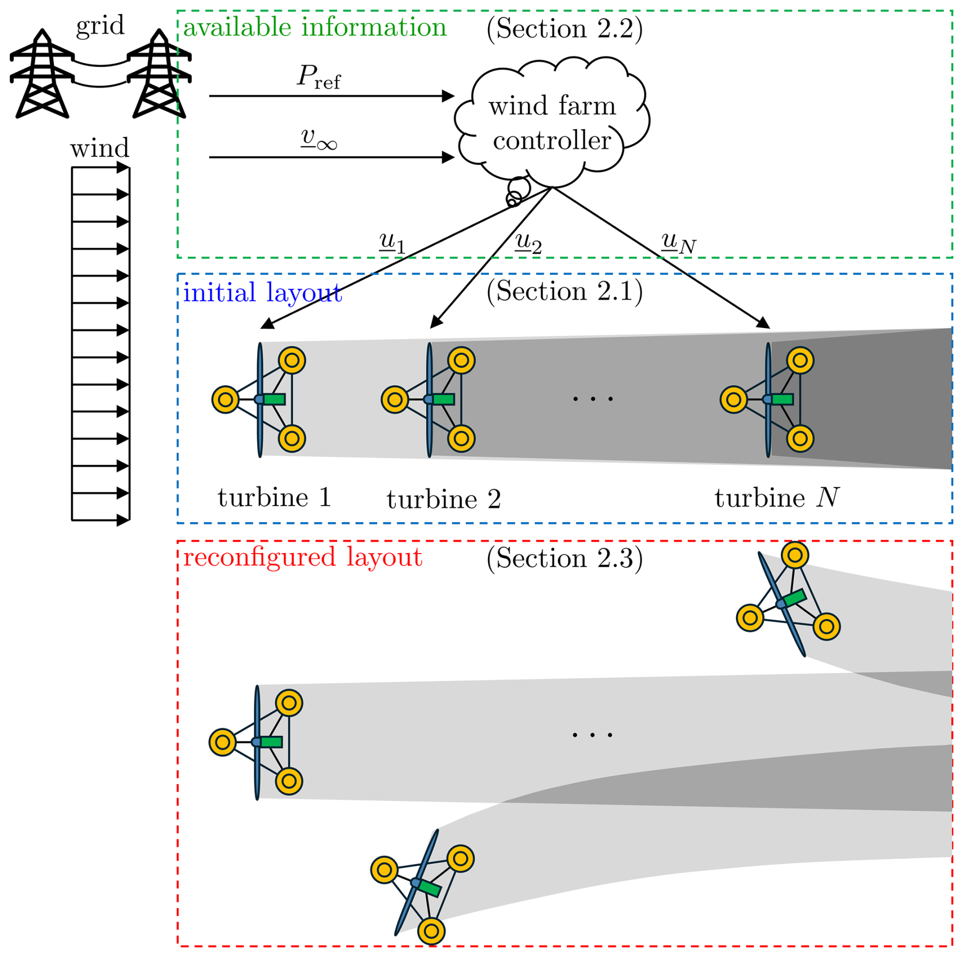
Figure 1Schematic of the control problem for an FOWF with a supervisory wind farm controller. In the baseline layout (center-blue box), turbines mounted on floating platforms settle to steady-state equilibrium positions where aerodynamic loading is balanced by mooring restoring forces; shaded regions illustrate wakes and wake overlap. The farm controller (top-green box) receives farm-level information (a grid power reference Pref and inflow condition v∞) and dispatches coordinated turbine commands to the turbine-level controllers. The resulting reconfigured layout (bottom-red box) illustrates how coordinated actions can reduce wake overlap and improve farm-level performance.
2.1 FOWFs with reconfigurable layouts
Consider first the case of an FOWF without centralized coordination. Suppose N turbines are initially aligned in a row, as shown in the center-blue box of Fig. 1. The inflow is assumed steady and unidirectional, approaching from the left and first interacting with turbine 1. Because each turbine is mounted on a floating platform, its absolute position is not fixed; instead, the wind pushes the platform to a steady-state equilibrium where aerodynamic thrust is balanced by restoring forces from the mooring lines. At this equilibrium, turbine 1 not only extracts energy from the flow at its rotor plane but also generates a wake of reduced wind speed, shown as a shaded gray region, which propagates downstream and interacts with turbine 2. This wake affects both the steady-state position and the power output of turbine 2. Turbine 2, in turn, moves to its steady-state equilibrium and produces its own wake (darker shade), further influencing subsequent turbines. This process continues across the farm, leading to cumulative wake interactions that reduce total energy production and impose unsteady loads on downstream rotors.
The inherent mobility of floating offshore wind turbines provides an opportunity to alleviate these wake-induced power losses and load increases. As shown in Fig. 2a and b, each turbine is mounted on a buoyant platform anchored to the seabed by mooring lines, which, if sufficiently long and slack, allow the platform to shift within a certain region. Controlled repositioning (Fig. 2c) can then be achieved by intentionally yawing the rotor out of alignment with the incoming wind, generating a lateral aerodynamic thrust that displaces the turbine to a new steady-state position. This mobility enables wind farm layouts to adapt dynamically to changing wind conditions, turbine health, and power requirements.
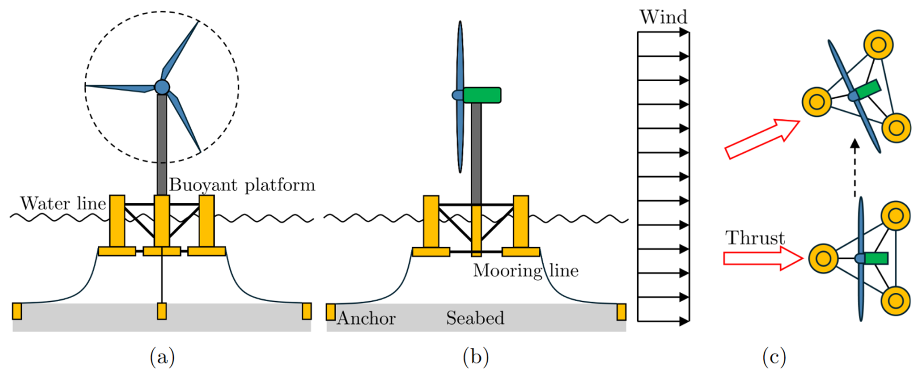
Figure 2Floating offshore wind turbine repositioning mechanism. (a) Front view and (b) side view highlight that the platform is not rigidly fixed to the seabed, allowing horizontal motion within a bounded region. (c) By introducing a yaw misalignment, the rotor thrust gains a lateral component that displaces the platform to a new steady-state equilibrium where aerodynamic loading is balanced by mooring restoring forces. This mobility enables layout reconfiguration in response to wind conditions and can be leveraged to reduce wake overlap at the farm level.
To fully exploit this repositioning capability and prevent the farm from operating at reduced efficiency under cumulative wake interactions, a supervisory wind farm controller is required. Such a controller can compute coordinated inputs for all turbines using the available farm-level information, thereby mitigating wake losses and improving overall performance.
2.2 Available information and control inputs
The supervisory wind farm controller, shown in the top-green box of Fig. 1, is responsible for coordinating the operation of all turbines within the farm. It is assumed to have access to two key pieces of information: the farm-level power reference Pref (MW) provided by the grid and the two-dimensional free-stream wind velocity v∞ (m s−1) at hub height, defined as
In the implementation of the controller, the free-stream wind speed at the hub height, which is difficult to measure in practice, is replaced by the rotor-effective wind-speed estimate of the most upstream turbine. This estimate can be obtained from standard turbine measurements or via lidar-assisted methods (Østergaard et al., 2007; Soltani et al., 2013; Held and Mann, 2019; Schlipf et al., 2013; Lio et al., 2021; Pamososuryo et al., 2025).
Based on this information, the controller computes coordinated control inputs ui for all N turbines, where ui denotes the control input vector for turbine i with . The specific components of ui are introduced later in Sect. 3. At this stage, it suffices to note that ui represents the control actions commanded by the wind farm controller, specifying how each turbine should operate or be repositioned. Once computed, these inputs are dispatched to the individual turbine controllers (Fig. 1), which then execute the prescribed actions at the local level. To compute these coordinated inputs, the wind farm controller must first be provided with the farm-level objectives that define the desired overall behavior of the farm.
2.3 Control objectives for wind farm controller
Through the available control inputs ui, the wind farm controller can pursue objectives that balance energy production with load mitigation. In this work, the control problem is formulated around two primary objectives:
-
Power maximization. Maximize the total electrical power output of the wind farm.
-
Power regulation. Adjust farm power to track a prescribed reference Pref. In this mode, wake mitigation is treated as an additional objective.
Power maximization is central to commercial wind farm operation, as maximizing energy capture directly improves economic returns and reduces the cost of electricity. Power regulation is particularly relevant for grid integration, where wind farms may be required to provide power setpoints consistent with system-level scheduling or ancillary service needs (Aho et al., 2012). When operating in regulation mode, the controller additionally seeks to mitigate wake effects, thereby improving downstream flow conditions and reducing fatigue loading on downstream turbines.
The resulting problem is therefore to design a wind farm controller (Fig. 1) that, based on the available measurements Pref and v∞, computes optimal control inputs ui. These inputs are dispatched to individual turbine controllers to achieve one of the power objectives, while also mitigating wake effects. For example, as shown in the bottom-red box of Fig. 1, the coordinated control inputs instruct turbine 1 to maintain its position, while directing turbines 2 through N to displace in alternate crosswind directions to reduce wake overlaps. Through this cooperative adjustment, the turbines collectively reshape the flow field, mitigate wake interactions, and redistribute power generation across the farm. The result is a reconfigured wind farm layout in which all turbines act in harmony at new steady states. The detailed wind farm controller design is presented in the following section.
To achieve the control objectives outlined in Sect. 2.3, we develop an integrated wind farm controller that unifies existing control strategies within an optimization-based framework. The remainder of this section is organized as follows. Section 3.1 reviews the individual strategies that serve as building blocks of the integrated approach, while Sect. 3.2 presents the detailed design of the integrated controller.
3.1 Integrated control approach
Wake interactions reduce downstream power production and increase fatigue-relevant loading (see Fig. 3a), motivating coordinated wind farm control. In this work, we manipulate a set of available turbine-level inputs to mitigate wake overlap and improve farm-level performance. For each turbine i, the control input vector introduced in Sect. 2.2 is defined as
where θi (°) is the net yaw angle (the misalignment between the incoming wind direction and the rotor axis), Pset,i (MW) is the power cap used to implement derating (i.e., turbine i is operated such that its power output does not exceed Pset,i), and βamp,i (°) is the mean-to-peak amplitude of the sinusoidal blade-pitch excitation used for Helix wake mixing at turbine i (). To avoid confusion, we distinguish turbine-level derating, implemented via Pset,i, from farm-level power regulation, which refers to tracking a prescribed farm power reference Pref through coordinated turbine commands. The remainder of this subsection reviews each control strategy in Fig. 3 and the ways in which each strategy manipulates these control inputs.
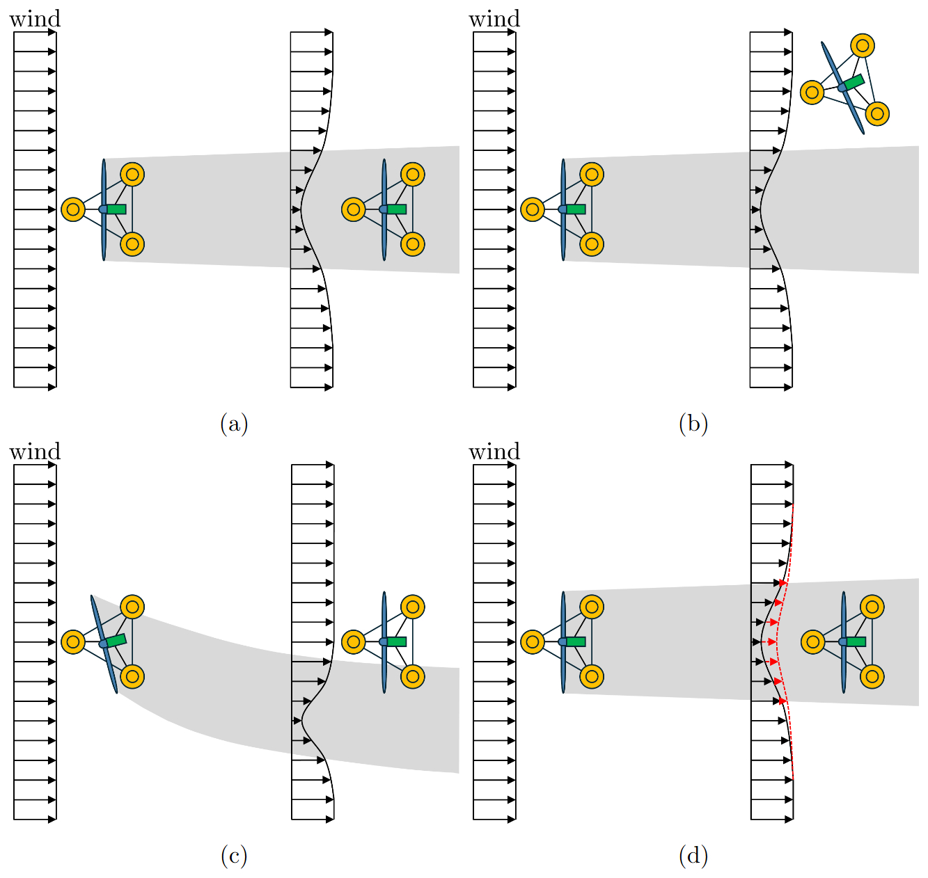
Figure 3Illustration of wake effects and wind farm control strategies: (a) wake effects, (b) turbine repositioning, (c) wake steering, and (d) power derating and dynamic wake mixing.
3.1.1 Turbine repositioning
Turbine repositioning sustains a net yaw angle θ misalignment to generate lateral thrust forces, displacing the floating platform to a new equilibrium (Fig. 3b). The net yaw angle θ quantifies the misalignment between the rotor plane and the incoming wind direction. It is defined as the sum of the nacelle yaw angle γ (°) and the platform yaw angle θz (°), minus the inflow direction ∠v∞ (Fig. 4):
By shifting the turbine laterally to the displaced equilibrium, repositioning can reduce the overlap between upstream wakes and downstream rotors, thereby enhancing energy capture and mitigating wake losses.
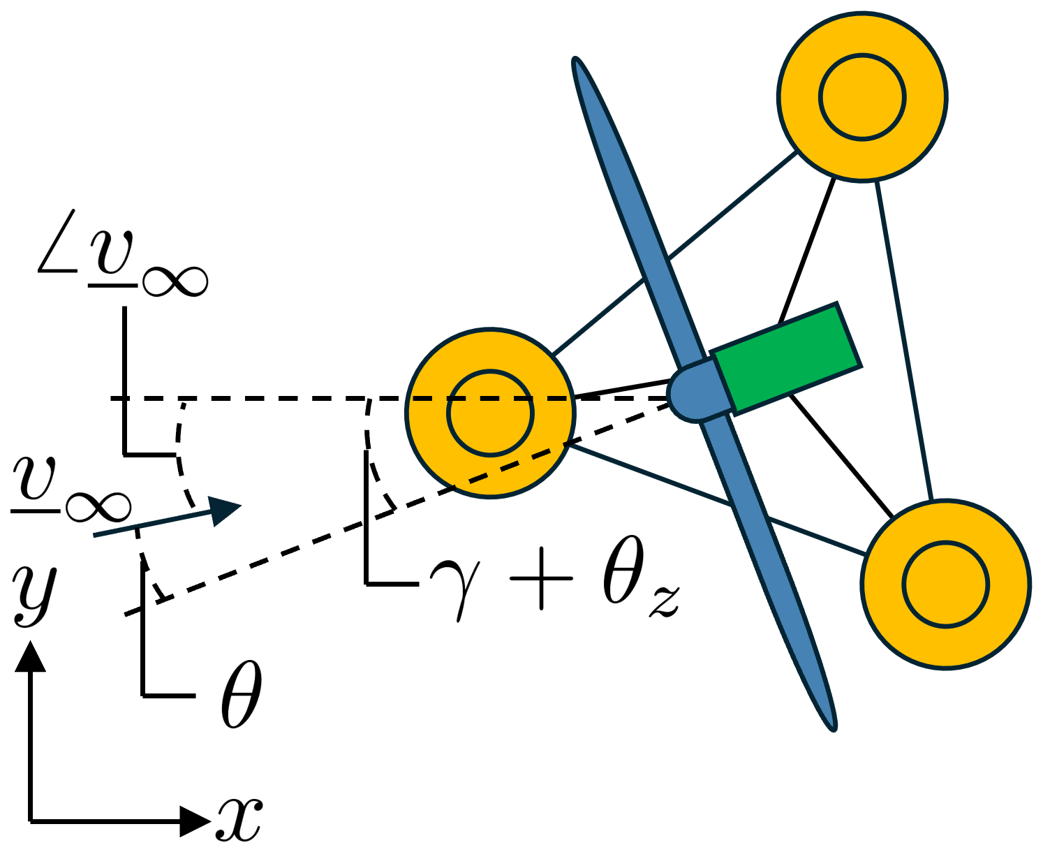
Figure 4Definition of the net yaw angle θ, which quantifies the rotor-plane misalignment relative to the incoming wind direction.
Despite its potential, the repositioning capability of each turbine in a farm may be limited depending on wind conditions. For the symmetric three-line mooring system in Fig. 5a, assume that the wind blows from left to right and the net yaw angle is set to θ=0. The turbine drifts downwind to an equilibrium where the wind-aligned mooring line becomes load-bearing and the other two lines slacken; consequently, crosswind motion encounters relatively little resistance and substantial repositioning becomes possible. By contrast, when the wind blows from right to left (Fig. 5b), the two right-side mooring lines remain taut and jointly oppose the motion, which increases restoring stiffness and severely restricts lateral displacement, reducing the effectiveness of repositioning. This directional dependence motivates augmenting repositioning with additional strategies, including wake steering, power derating, and dynamic wake mixing.
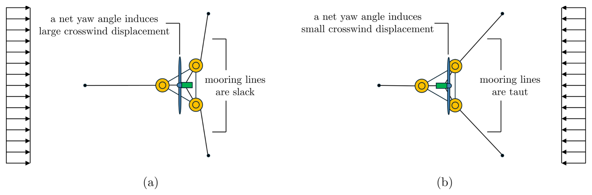
Figure 5Illustration of a limitation of turbine repositioning. (a) Wind from left to right: one mooring line is primarily load-bearing, while the other two slacken, allowing relatively unconstrained crosswind motion. (b) Wind from right to left: two mooring lines remain taut and oppose the motion, limiting crosswind displacement.
3.1.2 Other standalone and integrated control methods
When platform mobility is limited, the same net yaw angle θ can be used to deflect the wake laterally without displacing the platform (Fig. 3c). This deliberate misalignment steers the wake away from the downstream turbine, improving its inflow conditions. Power derating constrains turbines to prescribed power caps Pset, thereby reducing wake deficits and alleviating downstream impacts (Fig. 3d). Dynamic wake mixing (Fig. 3d) enhances turbulent diffusion to accelerate wake recovery. In this study, wake mixing is realized using FLORIS's Helix mode (periodic individual-blade pitch actuation), with the wake-mixing intensity parameterized by the mean-to-peak excitation amplitude βamp (van den Berg et al., 2024; Dammann et al., 2025; van Vondelen et al., 2025, 2026).
While each strategy provides distinct benefits, their combined application enables more flexible and effective farm-wide operation across diverse wind conditions. By integrating turbine repositioning, wake steering, power derating, and dynamic wake mixing within a unified optimization framework, the controller can adaptively select and coordinate strategies based on wind conditions and control objectives. This improves robustness in the practical sense that the controller can still mitigate wakes and meet farm-level goals even when one strategy is less effective. For example, when platform mobility is high, repositioning can be prioritized, whereas in constrained orientations, wake steering and dynamic wake mixing can take over.
3.2 Integrated controller design
The integrated controller computes the optimal control inputs ui by solving a constrained optimization problem formulated as
Here, the control input vector ui is defined in Eq. (2), and xi=[xiyi]T denotes the steady-state horizontal position of turbine i. We stack these variables as and . Similarly, , , and stack the turbine powers, inflow velocities, and thrust coefficients. The function J(⋅) in Eq. (4a) denotes the objective function that encodes the control objectives (Sect. 3.2.1). The wake model fFLORIS(⋅) in Eq. (4b) captures aerodynamic interactions among turbines and predicts steady-state power production (Sect. 3.2.2). The constraints in Eqs. (4c) and (4d) include equilibrium conditions balancing aerodynamic and mooring forces, as well as operational limits on the inputs (Sect. 3.2.3). The resulting nonlinear nonconvex problem is solved numerically using the methods described in Sect. 3.2.4.
3.2.1 Objective function
The objective function J(⋅) in Eq. (4a) is defined as
This objective function balances competing control objectives through weighted penalties. The first term enforces power-related objectives: for power maximization, the wind farm's reference power Pref can be set to a sufficiently high (possibly unattainable) upper-bound target, such as the sum of rated turbine powers, whereas for power regulation it corresponds to a prescribed farm-level target. Deviations of the actual output from this reference are penalized accordingly. The second term promotes wake mitigation by penalizing discrepancies between the free-stream wind velocity v∞ and the local velocity vi at the rotor of turbine i. Collectively, these terms enable the controller to satisfy power objectives while simultaneously reducing wake interactions. The power-tracking term and the wake-mitigation term in Eq. (5) have different units and typical magnitudes; therefore, the constant weight w is a key design parameter. It is to be selected via trial and error to balance the relative influence of the two terms.
3.2.2 Wake model
The turbine powers P, inflow velocities V, and thrust coefficients Ct in Eq. (4b) are predicted using FLORIS (National Renewable Energy Laboratory, 2025), an engineering wake model developed by the US National Renewable Energy Laboratory, which takes as inputs the stacked control vector U, turbine locations X, and free-stream wind condition v∞. FLORIS is computationally efficient, making it well suited for embedding in the proposed optimization-based controller. The wake-model components used in FLORIS, the implementation of the wind farm control methods in the model, and relevant modeling limitations are summarized next.
In this study, wake effects in FLORIS are represented by four submodels, each used with the default parameter values provided by FLORIS (National Renewable Energy Laboratory, 2025):
-
Velocity deficit model. For the wake velocity deficit, we use the empirical Gaussian wake model, which assumes a Gaussian distribution of the velocity deficit (Bastankhah and Porté-Agel, 2016; King et al., 2021).
-
Wake deflection model. Wake deflection is computed using FLORIS's empirical Gaussian deflection model based on yaw-misalignment wake-deflection formulations (Bastankhah and Porté-Agel, 2016; King et al., 2021).
-
Wake turbulence model. To account for added turbulence in turbine wakes, we employ the wake-induced mixing model in FLORIS, which generalizes wake-added turbulence in the empirical Gaussian wake model (National Renewable Energy Laboratory, 2026a). In this model, upstream turbines contribute to mixing in the flow, yielding a wake-induced mixing factor that is passed to the velocity deficit and wake deflection models to modify the wake width and the wake-centerline deflection, respectively.
-
Wake combination model. Wake effects from multiple turbines are combined using the sum-of-squares freestream superposition model (National Renewable Energy Laboratory, 2026b).
The wind farm control methods are implemented in FLORIS through the control inputs U as follows:
-
Wake steering. Wake steering is implemented by prescribing yaw misalignment commands θi, which modify turbine power/thrust and the resulting wake deflection in a steady-state sense.
-
Turbine repositioning. Turbine repositioning is represented by the same yaw commands θi but is coupled with a steady-state turbine position solver (see Sect. 3.2.4) that enforces static equilibrium between aerodynamic loading and mooring restoring forces to update the turbine positions. The updated positions are then evaluated in FLORIS, thereby changing wake overlap and farm performance.
-
Power derating. Power derating is implemented by prescribing a per-turbine power cap Pset,i. This setpoint is passed to FLORIS's “simple-derating” turbine operation model, which first evaluates the turbine power Pi and thrust coefficient from the power-thrust table at the local inflow and then enforces the cap as . When the cap limits the power output, FLORIS reduces the turbine thrust coefficient accordingly to reflect the curtailed operating point.
-
Helix wake mixing. Helix wake mixing is represented using FLORIS's built-in active wake control “helix” operation model, which parameterizes the time-averaged impact of helix pitch excitation on turbine power/thrust and wake recovery and has been calibrated in FLORIS as a standalone wake-mixing representation.
It should be noted that FLORIS has not yet been extensively validated for cases in which a turbine is simultaneously yaw-misaligned and operated in either derated mode or active wake-mixing mode. In our optimization framework, we nevertheless allow yaw misalignment to be applied concurrently with either power derating or Helix wake mixing for each turbine. Under such combined operation, FLORIS predicts steady-state changes in turbine power/thrust, wake deflection, and wake recovery; however, the corresponding results should be interpreted with this validation limitation in mind. Moreover, when wake steering and power derating/Helix wake mixing are applied simultaneously, yaw-induced power loss is not captured (as observed in our simulations) in the FLORIS prediction; therefore, to avoid overestimating power capture under yaw misalignment, we apply a yaw-power loss correction for yawed turbines, , with a parameter value pP=1.88 (Gebraad et al., 2016). For yaw-only wake-steering/turbine-repositioning cases, we do not apply this additional correction to avoid double counting.
3.2.3 Constraints
The optimization problem incorporates both equilibrium and operational constraints in Eqs. (4c) and (4d). First, each turbine must satisfy static force equilibrium between the aerodynamic thrust and the restoring forces of the mooring system to maintain its steady-state position. The aerodynamic thrust force on turbine i is given by
where ρ (kg m−3) is the air density, A (m2) is the rotor swept area, vi (m s−1) is the inflow velocity at the rotor plane, and Ct,i (–) is the thrust coefficient. In addition, all control inputs are constrained by minimum and maximum bounds, umin and umax, which ensure ui remains within physically realizable and safe operating ranges.
3.2.4 Solution method and implementation
The wake model and the force equilibrium in Eq. (4) are solved simultaneously using an iterative procedure. Given the free-stream wind velocity v∞ and candidate control inputs U, an initial guess of the turbine positions X is provided to FLORIS to compute the local velocities V, thrust coefficients Ct, and turbine powers P. The aerodynamic thrust forces Faero,i are then computed from V and Ct using Eq. (6). Next, for each turbine, the mooring restoring force Fmoor,i required to satisfy the equilibrium constraint Eq. (4c) is determined, and a precomputed look-up table generated from a quasi-static mooring model (Jonkman, 2009) is used to update the corresponding turbine positions X. The updated positions are fed back into FLORIS to recompute V, Ct, and P, and the iteration continues until the turbine positions converge. Once convergence is achieved, the converged P and V are used to evaluate the objective function in Eq. (5). Overall, the optimization problem formulated in Eq. (4) is nonlinear and nonconvex because of the complex wake interactions and spatial constraints, which can be solved using a global optimization solver. The next section presents simulation results that demonstrate the performance of the proposed controller under a wide range of wind conditions.
This section evaluates the performance of the wind farm controller through simulations conducted with the FLORIS engineering wake model. The simulations serve as a validation of the optimization framework developed in Sect. 3, demonstrating the controller's ability to maximize total power output and regulate farm-level power to a desired reference. In addition, they assess how effectively the controller mitigates wake effects. We first describe the simulation setup (Sect. 4.1), before presenting and discussing the comprehensive results (Sect. 4.2).
4.1 Simulation setup
The case study considers an FOWF with a reconfigurable layout comprising 10 turbines. The farm layout is shown in Fig. 6, which annotates the turbine indexing together with the corresponding neutral (no-wind) coordinates for each turbine (D=126 m). Each turbine is modeled as the NREL 5 MW offshore reference wind turbine (Jonkman et al., 2009) mounted on a semisubmersible platform (Robertson et al., 2014). Turbine, platform, and mooring system parameters follow the standard specifications in Jonkman et al. (2009); Robertson et al. (2014), with one key modification: the mooring line length is extended to 970 m. This extension expands the feasible motion range of each turbine, enabling controlled repositioning and allowing the wind farm layout to adapt dynamically to changing wind conditions.
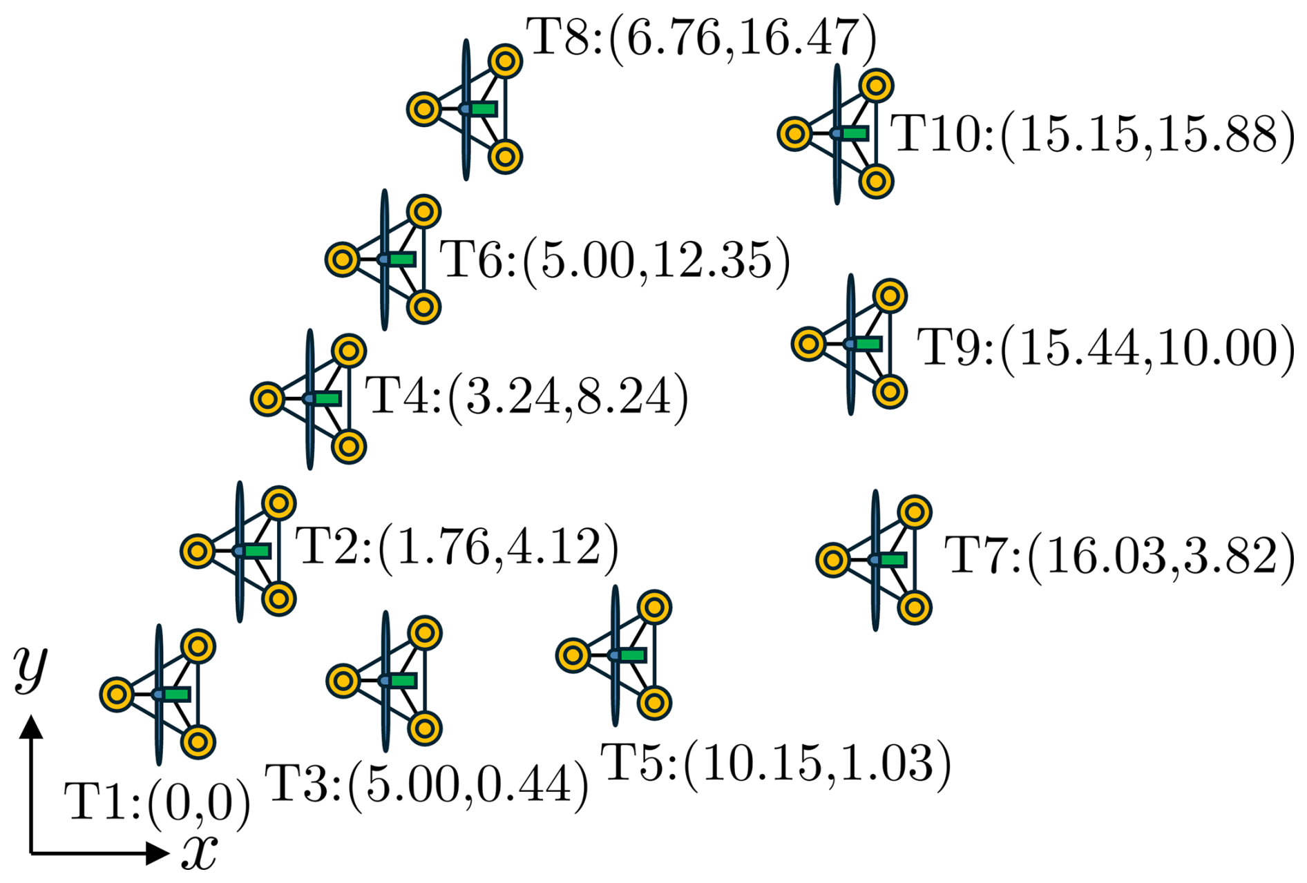
Figure 6Case-study 10-turbine FOWF layout used in the simulations. The schematic indicates the turbine indexing and the corresponding neutral (no-wind) coordinates for each turbine (D=126 m); the drawing is illustrative and not to scale.
The admissible control inputs in Eq. (4d) are defined as and . The control bounds are chosen to span a representative operating range for each strategy. The proposed coordination framework is evaluated in FLORIS for farm-level aerodynamic performance and does not explicitly quantify structural load or fatigue impacts of sustained yaw misalignment. To avoid excess fatigue loads, the net yaw offset is constrained to °; a coupled aeroelastic analysis (e.g., OpenFAST/FAST.Farm) is required in future work to assess the associated loading and fatigue implications. The derating command is bounded as MW, where MW corresponds to no derating and lower values impose curtailment. The Helix excitation amplitude is bounded to degrees, where corresponds to no wake-mixing actuation and the upper bound is consistent with excitation levels reported in prior studies (e.g., up to 4° in van den Berg et al., 2024, and up to 5° in Dammann et al., 2025).
For the numerical studies in this work, we solve Eq. (4) using a standard genetic algorithm as implemented in pymoo (Blank and Deb, 2020). The single-objective genetic algorithm was run with a population size of 80 and a maximum of 80 generations. For the considered case studies, the wall-clock time per optimization run was of the order of 15 min on a Windows 11 workstation with an Intel Core i9-13900HX CPU (24 cores/32 threads) and 32 GB RAM.
4.2 Results
4.2.1 Power maximization: performance over wind direction
The proposed integrated controller, which combines turbine repositioning, wake steering, and dynamic wake mixing, is benchmarked against (i) a combined repositioning + wake steering case, (ii) wake steering only, (iii) dynamic wake mixing only, and (iv) greedy control. Here, greedy control refers to the baseline operation in which each turbine independently maximizes its own power production without coordination across the farm. A “repositioning-only” case is not considered because, in this study, repositioning is achieved through net yaw offsets that modify the aerodynamic thrust direction to induce crosswind drift; the same yaw offsets inevitably steer the wake, so repositioning cannot be decoupled from wake steering. For the wake-steering-only and wake-mixing-only benchmarks, all turbines are held at their neutral (no-wind) positions. Power derating is excluded from this comparison because FLORIS simulations consistently show that it produces lower total output than greedy control across all wind speeds and inter-turbine spacings.
Figure 7 shows the maximum achievable farm power for steady inflow wind speeds of 4, 6, 8, and 10 m s−1 as the inflow direction is swept over the full 0–360° range (without wind-rose probability weighting). Wind direction is defined clockwise from the top of the wind farm (0° at the top). All simulations assume an ambient turbulence intensity of 0.06, a power-law vertical shear exponent of 0.12, and zero wind veer. Ocean wave effects are neglected. Each plot compares the different strategies, with the numbers displayed inside each plot indicating the wind farm power in megawatts. Results at higher wind speeds are omitted because even greedy control alone delivers rated farm power despite wake overlaps.
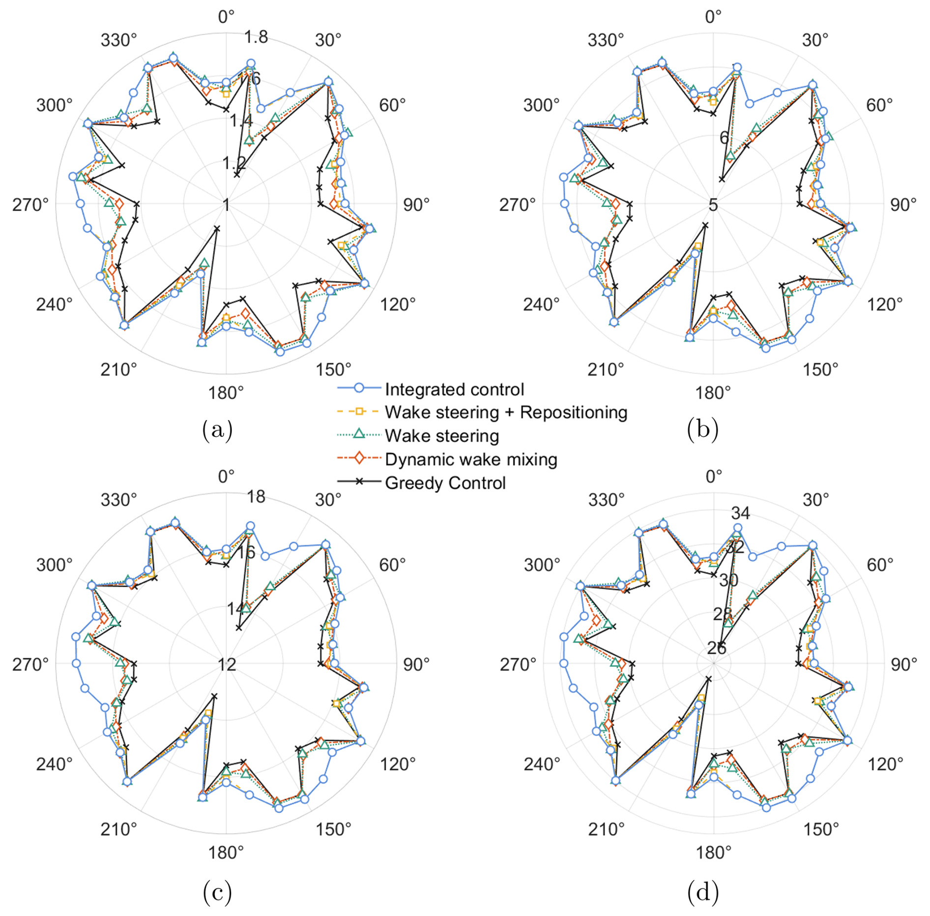
Figure 7Maximum achievable farm power as a function of inflow wind direction for four steady wind speeds: (a) 4 m s−1, (b) 6 m s−1, (c) 8 m s−1, and (d) 10 m s−1. Each polar plot compares the optimized farm power (MW; numbers annotated inside the plots) obtained under integrated control (turbine repositioning + wake steering + dynamic wake mixing), wake steering + repositioning, wake steering only, dynamic wake mixing only, and greedy control. Direction-dependent “notches” indicate inflow directions with severe wake effects and associated power deficits under greedy operation. Across wind speeds, the integrated controller consistently mitigates wake effects and provides the highest power envelope over direction, illustrating the benefit of coordinated control mechanisms.
Under greedy control, farm power exhibits a strong dependence on inflow direction, with pronounced deficits at directions that align multiple turbines with the wind and thus intensify wake overlap (seen as deep “notches” in the black curve). In these wake-dominated sectors, the integrated controller yields the largest benefits by filling in the troughs and recovering several megawatts at 10 m s−1, with similarly scaled gains at lower wind speeds. In contrast, for directions associated with weak wake interactions, the strategy curves nearly collapse, indicating that all approaches converge when there is little wake loss to mitigate.
A comparison of the benchmark strategies in Fig. 7 further highlights the value of coordination. In all four subplots (a–d), the integrated controller (blue line) delivers the highest power across directions by adaptively combining control mechanisms. The wake steering + repositioning case (orange line) generally remains close to the integrated control envelope, indicating that combining crosswind mobility with wake deflection captures much of the attainable improvement for this layout. Wake steering (green line) and dynamic wake mixing (red line) each provide clear improvements over greedy control (black line) while largely preserving the same direction-dependent performance pattern.
4.2.2 Power maximization: direction-averaged performance
To summarize overall performance across directions, Fig. 8 reports the average maximum farm power over all wind directions for inflow speeds between 4–10 m s−1, expressed as the percentage change relative to greedy control. Several trends are evident. First, all strategies yield positive mean gains, indicating that wake-mitigation actions provide net benefits when averaged over the full 0–360° direction sweep. Second, the fully integrated controller achieves the largest improvement at every wind speed, with the highest gain at 4 m s−1 (up to 6.5 %) and gains remaining around 3.9 % at 10 m s−1.
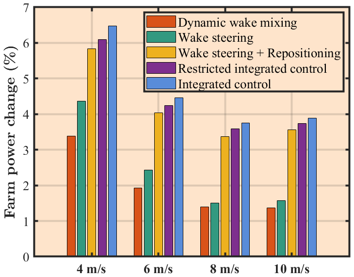
Figure 8Average improvement in maximum farm power over the full 0–360° inflow-direction sweep for wind speeds of 4–10 m s−1, expressed as percent change relative to greedy control. Bars compare dynamic wake mixing, wake steering, wake steering + repositioning, a restricted integrated-control case, and the fully integrated-control case. In the restricted integrated-control case, for each wind direction, all turbines in the farm are constrained to use the same control method, either yaw-based control (turbine repositioning/wake steering) or Helix wake mixing. The selected method may vary with wind direction, but the two methods are not used together within any given wind-direction case. The restricted case is included to provide a conservative benchmark for assessing the influence of excluding simultaneous same-turbine yaw-based control and Helix wake mixing.
At the same time, as discussed in Sect. 3.2.2, the simultaneous use of yaw-based control and Helix wake mixing is more complex than the standalone application of either method, and this combined operation has not been extensively validated in the present FLORIS model. Therefore, the fully integrated case may provide optimistic quantitative estimates of the achievable performance gains. To further assess the main conclusions, Fig. 8 also includes a restricted integrated-control case that provides a conservative lower-bound benchmark for the fully integrated study. In this restricted case, for each wind direction, all turbines in the farm are constrained to use the same control method, either yaw-based control (turbine repositioning/wake steering) or Helix wake mixing. The chosen method may vary with wind direction, but the two methods are not used together within a given wind-direction case. Even under this restriction, excluding the simultaneous same-turbine use of yaw-based control and Helix wake mixing does not eliminate the benefit of integrated control, although the resulting gains are smaller than those of the fully integrated case. These results indicate that the main qualitative benefit of the proposed integrated framework is preserved.
Among the remaining strategies, wake steering + repositioning provides the next-highest gains, followed by wake steering, and then dynamic wake mixing. The separation between wake steering + repositioning and wake steering alone highlights the additional value of exploiting crosswind mobility to reduce wake overlap beyond what can be achieved through wake deflection alone.
4.2.3 Power maximization: representative cases
To further illustrate how the integrated approach coordinates different strategies, Fig. 9 presents two representative power maximization cases at an inflow speed of 10 m s−1. Panels (a)–(c) correspond to wind from the left, and panels (d)–(f) correspond to wind from the lower left. For each inflow direction, panels (a) and (d) show the hub-height wind-speed field under greedy control, and panels (b) and (e) show the corresponding field under integrated control. In the left-inflow case, the farm power increases from 29.8 MW under greedy control to 33.7 MW under integrated control (+13.1 %); in the lower-left case, it increases from 26.0 to 27.6 MW (+6.2 %). Color denotes wind speed (red: near free-stream; white/blue: wake deficits), and the numbers annotated near each turbine report the corresponding local turbine inflow velocity. Panels (c) and (f) summarize the integrated-control solution with per-turbine bar plots of net yaw angle, Helix excitation amplitude, and crosswind displacement. The net yaw angle and Helix excitation amplitude are normalized by their maximum allowable magnitudes (20 and 5°), and the crosswind displacement is normalized by 120 m, chosen as a representative large lateral repositioning. Bars close to zero indicate negligible utilization of that strategy for a given turbine, whereas larger magnitudes indicate greater control effort. For yaw and displacement, bars extending above (below) zero correspond to positive (negative) values, indicating opposite yaw offsets and crosswind shift directions.
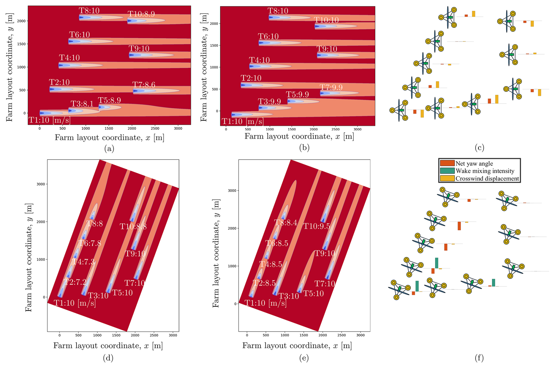
Figure 9Representative power maximization results at an inflow speed of 10 m s−1 for two inflow directions. Panels (a)–(c) correspond to wind from the left, and panels (d)–(f) correspond to wind from the lower left. For each case, panels (a) and (d) show the hub-height wind-speed field under greedy control, and panels (b) and (e) show the corresponding field under integrated control. Color denotes wind speed (red: near free-stream; white/blue: wake deficits), and the numbers annotated near each turbine indicate the corresponding local turbine inflow velocity. Panels (c) and (f) summarize the integrated control solution with per-turbine bar plots of net yaw angle, Helix excitation amplitude, and crosswind displacement. These quantities are normalized by 20°, 5°, and 120 m, respectively; bars close to zero indicate negligible use, whereas larger magnitudes indicate greater control effort, and bars above/below zero indicate opposite yaw/displacement directions. With substantial crosswind mobility in the left-inflow case, the controller primarily exploits repositioning to reduce wake overlap and maximize farm power. With limited crosswind mobility in the lower-left inflow case, the controller relies on wake steering and Helix wake mixing to mitigate wake effects.
In Fig. 9a–c, where the wind originates from the left, turbines have substantial crosswind mobility. Consequently, turbine repositioning is prioritized to mitigate wake effects and enhance overall farm power. For example, to reduce wake interactions among T1, T3, and T5, T1 applies a negative net yaw angle to shift downward, T3 remains almost at the same position, and T5 applies a positive net yaw angle to shift upward. As a result, all three turbines gain access to near-free-stream wind and generate higher overall power. Similarly, wake interactions between T2 and T7, as well as between T8 and T10, are alleviated by repositioning the turbines in opposite crosswind directions. T9 experiences a mild wake influence; although the annotated inflow speed is 10 m s−1, this value is rounded, and the true inflow is slightly below the free-stream speed. Accordingly, T4 and T9 exhibit small opposite crosswind shifts (as seen in the small orange bars in panel c) to further reduce wake overlap. Meanwhile, T6 is neither waked nor a wake source for downstream turbines and therefore remains unchanged.
When the wind originates from the lower left (Fig. 9d–f), crosswind mobility is limited, and wake steering together with dynamic wake mixing become the dominant strategies. To mitigate wake interactions among T1, T2, T4, T6, and T8, T1 and T2 rely on a combination of wake steering and dynamic wake mixing, while T4 and T6 employ wake steering alone. T8, being the most downstream turbine, makes only a small adjustment. In addition, T5 applies dynamic wake mixing accompanied by a small yaw offset to enhance the inflow to T10; T10 itself applies no control action. The remaining T3, T7, and T9 are unaffected by wakes and therefore remain unchanged.
Overall, these cases highlight how the integrated controller adaptively coordinates strategies to maximize performance under varying wind conditions.
4.2.4 Power regulation with wake penalties
This case study examines farm-level power regulation with an added wake-overlap penalty, where the integrated controller coordinates turbine repositioning, wake steering, and power derating. The constant weight in Eq. (5) is set to w=800. Results are reported for a below-rated inflow speed of 10 m s−1 under two representative inflow directions, with corresponding farm-level power references (Pref=32 MW for inflow from the left and Pref=27 MW for inflow from the lower left); see Fig. 10. In both cases, the controller closely tracks the prescribed reference. The figure format matches the power maximization cases, except that panels (c) and (f) replace the Helix excitation amplitude with the normalized derating level .
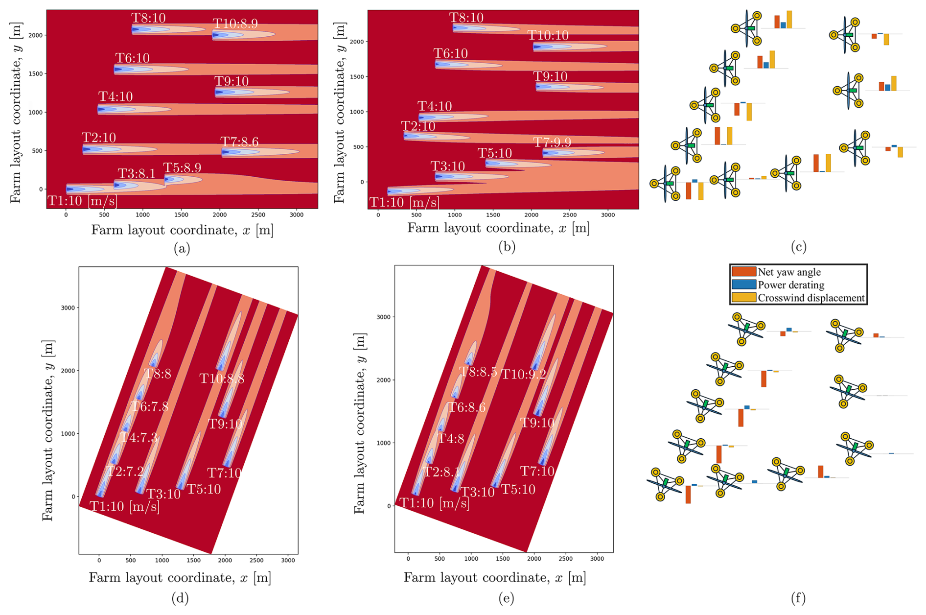
Figure 10Representative power-regulation results at an inflow speed of 10 m s−1 for two inflow directions. Panels (a)–(c) correspond to wind from the left with Pref=32 MW, and panels (d)–(f) correspond to wind from the lower left with Pref=27 MW. For each case, panels (a) and (d) show the hub-height wind-speed field under greedy control, and panels (b) and (e) show the corresponding field under integrated control. Color denotes wind speed (red: near free-stream; white/blue: wake deficits), and the numbers annotated near each turbine indicate the corresponding local turbine inflow velocity. Panels (c) and (f) summarize the integrated control solution with per-turbine bar plots of net yaw angle, derating level , and crosswind displacement. In the left-inflow case, the controller leverages the available crosswind mobility to reposition turbines and alleviate wake overlap, while using distributed derating and associated yaw-induced power reduction to satisfy the farm-level power reference. With limited crosswind mobility in the lower-left inflow case, the controller relies on wake steering, together with distributed derating, to reduce wake overlap while tracking the farm-level power reference.
For inflow from the left (Fig. 10a–c), greedy control produces clear wake deficits for T3, T5, T7, and T10, whose annotated inflows drop to 8.1, 8.9, 8.6, and 8.9 m s−1, respectively, while the remaining turbines stay at the 10 m s−1 free stream (panel a). Under integrated control (panel b), these deficits are visibly reduced: T3, T5, and T10 recover to 10 m s−1, and T7 increases to 9.9 m s−1. Panel (c) indicates that wake mitigation is achieved primarily through crosswind repositioning, while farm-level power tracking is enforced through distributed per-turbine derating and net-yaw offsets. Notably, T4, T6, and T9, located in free-stream inflow and with minimal downstream influence, also apply large yaw offsets, reflecting yaw's dual role: it generates lateral repositioning forces and reduces the turbine's own power, thereby decreasing wake overlap while simultaneously contributing to regulation.
For inflow from the lower left (Fig. 10d–f), the aligned wakes under greedy control produce pronounced deficits at T2, T4, T6, T8, and T10, with annotated inflows of 7.2, 7.3, 7.8, 8, and 8.8 m s−1, respectively (panel d). Under integrated control, the inflow to these waked turbines increases to 8.1, 8, 8.6, 8.5, and 9.2 m s−1 (panel e). Consistent with the small orange bars in panel (f), crosswind repositioning is limited for this inflow direction; consequently, the controller relies on wake steering together with per-turbine derating to simultaneously reduce wake overlap and regulate farm-level power.
As discussed in Sect. 3.2.2, when yaw-based control and power derating are applied simultaneously to the same turbine in the present study, the power of the yawed turbine is evaluated by applying the correction to the derated power, where pP=1.88 (Gebraad et al., 2016). However, this representation remains approximate. Recent studies indicate that, for a yawed turbine, the power depends on the yaw angle, the thrust coefficient, and the control strategy governing the rotor, rather than being described by a single constant cosine-law exponent (Heck et al., 2023; Tamaro et al., 2024). Therefore, the combined effect of yaw misalignment and power derating is not fully captured by the present model.
To further assess the impact of this modeling limitation, we considered a restricted benchmark using the mixed operation model in FLORIS, in which each turbine was allowed to use either yaw-based control or power derating, but not both simultaneously. For the two representative cases considered here, the restricted benchmark still achieved the farm-level power-regulation objective while mitigating wake overlap, with results similar to those of the unrestricted integrated case. The detailed results are therefore omitted here for brevity.
Overall, these cases show that the controller maintains reliable farm-level tracking via distributed derating and yaw-induced power reduction while adaptively using wake steering and turbine repositioning to reduce wake overlap.
This paper proposed an integrated control method for floating offshore wind farms (FOWFs) with reconfigurable layouts, unifying turbine repositioning, wake steering, power derating, and Helix wake mixing within a single framework. The controller operates in two modes: power maximization, where the objective is to increase total farm output, and power regulation, where the objective is to track a prescribed farm-level reference while mitigating wake interactions. The control problem was formulated as a nonlinear nonconvex optimization problem. Farm-level aerodynamic performance was evaluated using the FLORIS engineering wake model augmented with a steady-state turbine position solver, and the resulting optimization was solved numerically using a genetic algorithm.
Simulation studies demonstrated that the proposed controller successfully achieves these objectives. In power maximization mode, it delivered up to 6.5 % higher total power compared to baseline operation, with the corresponding conservative lower-bound benchmark still achieving up to 6.1 % improvement. In power regulation mode, it simultaneously tracked the prescribed farm-level reference and mitigated wake overlaps. The results further revealed how the integrated approach adapts to different wind conditions: in maximization mode, the controller prioritizes turbine repositioning when crosswind mobility is feasible, shifting adaptively to wake steering and Helix wake mixing when mobility is restricted. In regulation mode, it achieves reference tracking through power derating and yaw-induced power reduction, while coordinating turbine repositioning and wake steering to reduce wake interactions.
Overall, these findings demonstrate that coordinating multiple control strategies (turbine repositioning, wake steering, power derating, and Helix wake mixing), rather than applying them in isolation, can significantly improve energy capture and enhance operational flexibility in FOWFs. This work highlights the potential of integrated control frameworks to overcome the limitations of standalone methods and to support the broader deployment of floating offshore wind energy. Potential future research directions include higher-fidelity assessment of cases where multiple control actions are applied together on the same turbine, as well as extension of the present framework toward control codesign. In particular, future work should further validate cases in which yaw-based control is applied together with Helix wake mixing or power derating on the same turbine, using higher-fidelity simulations such as large-eddy simulations, since such same-turbine combined operation has not yet been validated in the present study. Although the additional benchmark cases in this study support the main qualitative conclusions when these actions are not assigned together to the same turbine, further work along these directions would strengthen confidence in the quantitative predictions for the unrestricted integrated-control cases. In addition, the present framework can be extended toward control codesign: rather than assuming an FOWF is already installed, mooring system configurations could be optimized to ensure that at least a subset of turbines retains mobility under any wind condition, thereby further improving overall farm performance. Progress in these directions would further enhance the operational efficiency and economic viability of next-generation offshore wind energy systems.
The code used in this study is publicly available at https://drive.google.com/drive/folders/1h6ebwumd06PdEuX38KJgqEwQK9Lhss3e (Niu and Nagamune, 2026).
All results presented in this paper can be reproduced using the code, which is publicly available as stated in the “Code availability” section.
YN contributed to the conceptualization, methodology, software, formal analysis, investigation, visualization, and writing (original draft preparation). RN contributed to the conceptualization, validation, writing (review and editing), supervision, project administration, and funding acquisition.
The contact author has declared that neither of the authors has any competing interests.
Publisher's note: Copernicus Publications remains neutral with regard to jurisdictional claims made in the text, published maps, institutional affiliations, or any other geographical representation in this paper. The authors bear the ultimate responsibility for providing appropriate place names. Views expressed in the text are those of the authors and do not necessarily reflect the views of the publisher.
The authors would like to thank Zekai Chen, Casey Heiskell, and Yuting Wu for their helpful discussions and constructive feedback during the course of this research.
This research has been supported by the Natural Sciences and Engineering Research Council of Canada (grant no. RGPIN-2023-03339).
This paper was edited by Johan Meyers and reviewed by two anonymous referees.
Aho, J., Buckspan, A., Laks, J., Fleming, P., Jeong, Y., Dunne, F., Churchfield, M., Pao, L., and Johnson, K.: A tutorial of wind turbine control for supporting grid frequency through active power control, in: 2012 American Control Conference, Montreal, QC, Canada, https://doi.org/10.1109/ACC.2012.6315180, 3120–3131, 2012. a
Andersson, L. E., Anaya-Lara, O., Tande, J. O., Merz, K. O., and Imsland, L.: Wind farm control – Part I: a review on control system concepts and structures, IET Renew. Power Gen., 15, 2085–2108, 2021. a
Barthelmie, R. J., Hansen, K., Frandsen, S. T., Rathmann, O., Schepers, J. G., Schlez, W., Phillips, J., Rados, K., Zervos, A., Politis, E. S., and Chaviaropoulos, P. K.: Modelling and measuring flow and wind turbine wakes in large wind farms offshore, Wind Energy, 12, 431–444, 2009. a
Bastankhah, M. and Porté-Agel, F.: Experimental and theoretical study of wind turbine wakes in yawed conditions, J. Fluid Mech., 806, 506–541, 2016. a, b
Blank, J. and Deb, K.: Pymoo: multi-objective optimization in Python, IEEE Access, 8, 89497–89509, 2020. a
Boersma, S., Doekemeijer, B. M., Gebraad, P. M. O., Fleming, P. A., Annoni, J., Scholbrock, A. K., Frederik, J. A., and van Wingerden, J.-W.: A tutorial on control-oriented modeling and control of wind farms, in: 2017 American Control Conference, Seattle, WA, USA, https://doi.org/10.23919/ACC.2017.7962923, 1–18, 2017. a
Burton, T., Jenkins, N., Sharpe, D., and Bossanyi, E.: Wind Energy Handbook, Wiley, Hoboken, NJ, USA, 2nd edn., https://doi.org/10.1002/9781119992714, 2011. a
Carmo, L., Jonkman, J., and Thedin, R.: Investigating the interactions between wakes and floating wind turbines using FAST.Farm, Wind Energ. Sci., 9, 1827–1847, https://doi.org/10.5194/wes-9-1827-2024, 2024. a
Damiani, R., Dana, S., Annoni, J., Fleming, P., Roadman, J., van Dam, J., and Dykes, K.: Assessment of wind turbine component loads under yaw-offset conditions, Wind Energ. Sci., 3, 173–189, https://doi.org/10.5194/wes-3-173-2018, 2018. a
Dammann, T., van der Hoek, D., Yu, W., and van Wingerden, J.-W.: Enhanced wind farm performance via active wake control: a steady-state approach, in: 2025 American Control Conference, Denver, CO, USA, https://doi.org/10.23919/ACC63710.2025.11107695, 2856–2861, 2025. a, b, c, d
Doekemeijer, B. M., van Wingerden, J.-W., and Fleming, P. A.: A tutorial on the synthesis and validation of a closed-loop wind farm controller using a steady-state surrogate model, in: 2019 American Control Conference, Philadelphia, PA, USA, https://doi.org/10.23919/ACC.2019.8815126, 2825–2836, 2019. a
Dong, H., Xie, J., and Zhao, X.: Wind farm control technologies: from classical control to reinforcement learning, Progress in Energy, 4, 032006, https://doi.org/10.1088/2516-1083/ac6cc1, 2022. a
Fleming, P., Gebraad, P. M. O., Lee, S., van Wingerden, J.-W., Johnson, K., Churchfield, M., Michalakes, J., Spalart, P., and Moriarty, P.: Simulation comparison of wake mitigation control strategies for a two-turbine case, Wind Energy, 18, 2135–2143, 2015. a
Froese, G., Ku, S. Y., Kheirabadi, A. C., and Nagamune, R.: Optimal layout design of floating offshore wind farms, Renew. Energ., 190, 94–102, 2022. a
Gao, Y., Padmanabhan, A., Chen, O., Kheirabadi, A. C., and Nagamune, R.: A baseline repositioning controller for a floating offshore wind farm, in: 2022 American Control Conference, Atlanta, GA, USA, https://doi.org/10.23919/ACC53348.2022.9867574, 4224–4229, 2022. a
Gebraad, P. M. O., Teeuwisse, F. W., van Wingerden, J. W., Fleming, P. A., Ruben, S. D., Marden, J. R., and Pao, L. Y.: Wind plant power optimization through yaw control using a parametric model for wake effects – a CFD simulation study, Wind Energy, 19, 95–114, 2016. a, b
Goit, J. P. and Meyers, J.: Optimal control of energy extraction in wind-farm boundary layers, J. Fluid Mech., 768, 5–50, 2015. a, b
Han, C., Homer, J. R., and Nagamune, R.: Movable range and position control of an offshore wind turbine with a semi-submersible floating platform, in: 2017 American Control Conference, Seattle, WA, USA, https://doi.org/10.23919/ACC.2017.7963147, 1389–1394, 2017. a
Heck, K. S., Johlas, H. M., and Howland, M. F.: Modelling the induction, thrust and power of a yaw-misaligned actuator disk, J. Fluid Mech., 959, A9, https://doi.org/10.1017/jfm.2023.129, 2023. a
Held, D. P. and Mann, J.: Lidar estimation of rotor-effective wind speed – an experimental comparison, Wind Energ. Sci., 4, 421–438, https://doi.org/10.5194/wes-4-421-2019, 2019. a
Jard, T. and Snaiki, R.: Real-time repositioning of floating wind turbines using model predictive control for position and power regulation, Wind, 3, 131–150, 2023. a
Johnson, K. E. and Thomas, N.: Wind farm control: addressing the aerodynamic interaction among wind turbines, in: 2009 American Control Conference, St. Louis, MO, USA, https://doi.org/10.1109/ACC.2009.5160152, 2104–2109, 2009. a
Jonkman, J. M.: Dynamics of offshore floating wind turbines – model development and verification, Wind Energy, 12, 459–492, 2009. a
Jonkman, J., Butterfield, S., Musial, W., and Scott, G.: Definition of a 5-MW Reference Wind Turbine for Offshore System Development, Tech. Rep. NREL/TP-500-38060, National Renewable Energy Lab., Golden, CO, USA, https://doi.org/10.2172/947422, 2009. a, b
Kheirabadi, A. C. and Nagamune, R.: A quantitative review of wind farm control with the objective of wind farm power maximization, J. Wind Eng. Ind. Aerod., 192, 45–73, 2019. a
Kheirabadi, A. C. and Nagamune, R.: Real-time relocation of floating offshore wind turbine platforms for wind farm efficiency maximization: an assessment of feasibility and steady-state potential, Ocean Eng., 208, 107445, https://doi.org/10.1016/j.oceaneng.2020.107445, 2020. a, b
Kheirabadi, A. C. and Nagamune, R.: A low-fidelity dynamic wind farm model for simulating time-varying wind conditions and floating platform motion, Ocean Eng., 234, 109313, https://doi.org/10.1016/j.oceaneng.2021.109313, 2021a. a
Kheirabadi, A. C. and Nagamune, R.: Real-time relocation of floating offshore wind turbines for power maximization using distributed economic model predictive control, in: 2021 American Control Conference, New Orleans, LA, USA, https://doi.org/10.23919/ACC50511.2021.9483056, 3077–3081, 2021b. a
Kilinc, U.: Dynamic wind farm layout optimization: To find the optimal spots for movable floating offshore wind turbines through dynamic repositioning, Master's thesis, Delft University of Technology, Delft, the Netherlands, https://resolver.tudelft.nl/uuid:4a8d2451-e766-4c77-bb47-c65b25c70ab1 (last access: 17 March 2026), 2022. a
King, J., Fleming, P., King, R., Martínez-Tossas, L. A., Bay, C. J., Mudafort, R., and Simley, E.: Control-oriented model for secondary effects of wake steering, Wind Energ. Sci., 6, 701–714, https://doi.org/10.5194/wes-6-701-2021, 2021. a, b
Lio, W. H., Li, A., and Meng, F.: Real-time rotor effective wind speed estimation using Gaussian process regression and Kalman filtering, Renew. Energ., 169, 670–686, 2021. a
Mahfouz, M. Y. and Cheng, P.-W.: A passively self-adjusting floating wind farm layout to increase the annual energy production, Wind Energy, 26, 251–265, 2023. a
Musial, W., Spitsen, P., Duffy, P., Beiter, P., Marquis, M., Hammond, R., and Shields, M.: Offshore Wind Market Report: 2022 Edition, Tech. Rep. DOE/GO-102022-5765, U.S. Department of Energy Office of Energy Efficiency and Renewable Energy, Washington, DC, USA, https://doi.org/https://doi.org/10.2172/1893268, 2022. a, b
National Renewable Energy Laboratory: “FLORIS version 4.4.2.” GitHub, https://github.com/NatLabRockies/floris, last access: 22 August 2025. a, b, c
National Renewable Energy Laboratory: “floris.core.wake_turbulence.wake_induced_mixing”, https://natlabrockies.github.io/floris/_autosummary/floris.core.wake_turbulence.wake_induced_mixing.html, last access: 5 January 2026a. a
National Renewable Energy Laboratory: “floris.core.wake_combination.sosfs”, https://natlabrockies.github.io/floris/_autosummary/floris.core.wake_combination.sosfs.html, last access: 5 January 2026b. a
Niu, Y., Lathi, P. P., and Nagamune, R.: Floating offshore wind farm control via turbine repositioning with aerodynamic force, in: 2023 American Control Conference, San Diego, CA, USA, https://doi.org/10.23919/ACC55779.2023.10155902, 2542–2547, 2023. a
Niu, Y., Dwivedi, A., Sathiaraj, J., Lathi, P. P., and Nagamune, R.: Floating offshore wind farm control via turbine repositioning: unlocking the potential unique to floating offshore wind, IEEE Control Systems, 44, 106–129, 2024. a
Niu, Y. and Nagamune, R.: Code for an integrated control framework for floating offshore wind farms, https://drive.google.com/drive/folders/1h6ebwumd06PdEuX38KJgqEwQK9Lhss3e (last access: 18 January 2026), 2026. a
Østergaard, K. Z., Brath, P., and Stoustrup, J.: Estimation of effective wind speed, J. Phys. Conf. Ser., 75, Art. no. 012082, 2007. a
Pamososuryo, A. K., Spagnolo, F., and Mulders, S. P.: Analysis and calibration of optimal power balance rotor-effective wind speed estimation schemes for large-scale wind turbines, Wind Energ. Sci., 10, 987–1006, https://doi.org/10.5194/wes-10-987-2025, 2025. a
Robertson, A., Jonkman, J., Masciola, M., Song, H., Goupee, A., Coulling, A., and Luan, C.: Definition of the Semisubmersible Floating System for Phase II of OC4, Tech. Rep. NREL/TP-5000-60601, National Renewable Energy Lab., Golden, CO, USA, https://doi.org/10.2172/1155123, 2014. a, b
Schlipf, D., Cheng, P. W., and Mann, J.: Model of the correlation between lidar systems and wind turbines for lidar-assisted control, J. Atmos. Ocean. Tech., 30, 2233–2240, 2013. a
Soltani, M. N., Knudsen, T., Svenstrup, M., Wisniewski, R., Brath, P., Ortega, R., and Johnson, K.: Estimation of rotor effective wind speed: a comparison, IEEE T. Contr. Syst. T., 21, 1155–1167, 2013. a
Steinbuch, M., de Boer, W. W., Bosgra, O. H., Peters, S. A. W. M., and Ploeg, J.: Optimal control of wind power plants, J. Wind Eng. Ind. Aerod., 27, 237–246, 1988. a
Tamaro, S., Campagnolo, F., and Bottasso, C. L.: On the power and control of a misaligned rotor – beyond the cosine law, Wind Energ. Sci., 9, 1547–1575, https://doi.org/10.5194/wes-9-1547-2024, 2024. a
van den Berg, D., D. Tavernier, D., Marten, D., Saverin, J., and van Wingerden, J.-W.: Wake mixing control for floating wind farms: analysis of the implementation of the helix wake mixing strategy on the IEA 15-MW floating wind turbine, IEEE Control Systems, 44, 81–105, 2024. a, b, c, d, e, f
van Vondelen, A. A., van der Hoek, D. C., Navalkar, S. T., and van Wingerden, J.-W.: Experimental validation of synchronized Helix wake mixing control, Renew. Energ., 257, 124768, https://doi.org/10.1016/j.renene.2025.124768, 2026. a, b, c
van Vondelen, A. A. W., Coquelet, M., Navalkar, S. T., and van Wingerden, J.-W.: Synchronized Helix wake mixing control, Wind Energ. Sci., 10, 2411–2433, https://doi.org/10.5194/wes-10-2411-2025, 2025. a, b, c
Xue, L., Wang, J., Zhao, L., Wei, Z., Yu, M., and Xue, Y.: Wake interactions of two tandem semisubmersible floating offshore wind turbines based on FAST.Farm, Journal of Marine Science and Engineering, 10, 1962, https://doi.org/10.3390/jmse10121962, 2022. a
- Abstract
- Introduction
- Control problem formulation for FOWFs with reconfigurable layouts
- Integrated wind farm controller design
- Simulation results
- Conclusions
- Code availability
- Data availability
- Author contributions
- Competing interests
- Disclaimer
- Acknowledgements
- Financial support
- Review statement
- References
- Abstract
- Introduction
- Control problem formulation for FOWFs with reconfigurable layouts
- Integrated wind farm controller design
- Simulation results
- Conclusions
- Code availability
- Data availability
- Author contributions
- Competing interests
- Disclaimer
- Acknowledgements
- Financial support
- Review statement
- References