the Creative Commons Attribution 4.0 License.
the Creative Commons Attribution 4.0 License.
 | 14 Jan 2026
Hollow-forged AHD steel rotor shafts for wind turbines – a case study on power density, costs and GWP
Christian Hollas
Georg Jacobs
Vitali Züch
Julian Röder
Moritz Gouverneur
Niklas Reinisch
David Bailly
Alexander Gramlich
Hollow-forging and air-hardening ductile (AHD) forging steels are a novel manufacturing process and steel grade for the wind energy sector. Together they enable new rotor shaft design possibilities for wind turbines. Hollow forging combines the high material strength of a solid-forged shaft with direct inner contour manufacturing similar to casting. To compare an AHD steel hollow-forged rotor shaft to a state-of-the-art cast rotor shaft, a case study is carried out, focusing on power density, manufacturing costs and (manufacturing) global warming potential (GWP). To ensure comparability between the hollow-forged and cast rotor shaft, two predesigns of a main bearing unit (MBU), consisting of the rotor shaft, main bearings and bearing housings, are generated via a structural integrity assessment and calculation of the bearing lifetime according to ISO 76 / 281. The resulting hollow rotor shaft has 37 % less mass than the cast rotor shaft, corresponding to a 16.5 % lower MBU mass. For the hollow-forged rotor shaft to be comparable to casting regarding manufacturing costs, the forging surcharges need to be less than 50 % of the shaft mass. Due to the shortened heat treatment of AHD steels and the use of green steel, the manufacturing GWP of hollow forging is comparable to casting and makes up around one-third of the GWP of the entire MBU.
- Article
(2227 KB) - Full-text XML
- BibTeX
- EndNote


To reduce the levelised cost of electricity (LCOE) of wind energy, there has been a notable, still-ongoing shift towards larger wind turbines (WTs) with higher power ratings (Nejad et al., 2022). The growth in power and rotor diameter directly increases the loads on the WT drive train (Euler et al., 2023). To cope with the increased loads, the drive train needs to be redesigned, resulting in heavier components. Consequently, the costs of the drive train components rise, while the required, sturdier tower and increased logistic expenditure further add to the capital expenditure (CAPEX). Therefore, a need for an increase in drive train power density (power per mass) arises.
Taking the rotor shaft as an example, via novel manufacturing processes like hollow forging (Kwon et al., 2016), combined with new steel grades like air-hardening ductile (AHD) forging steels, a leap in main bearing unit (MBU) power density is possible. The increase in power density is a result of better material utilisation and higher material strengths compared to state-of-the-art manufacturing processes and materials. AHD steels harden directly during the cooling from the forging heat, resulting in a martensitic microstructure, similar to standard high-strength steels. Thus, the energy-intensive quench and tempering (QT) process is omitted, reducing energy consumption and therefore global warming potential (GWP) compared to QT-forging steel (Gramlich et al., 2023). As shown in a previous study (Hollas et al., 2024), MBUs with hollow-forged rotor shafts achieve higher power densities than those with cast rotor shafts, particularly when forged from AHD steel.
A hollow-forged shaft is formed over a cylindrical or conical mandrel, which defines the inner geometry of the shaft. Hollow forging combines the high material strengths of QT steel (solid forging) with the direct manufacturing of the shaft bore (similar to casting). A larger inner shaft diameter (d) enables higher section modulus (SBending; see Eq. 1) for a fixed-shaft cross section (A; outer shaft diameter D calculated given Eq. 2). This results in better material utilisation regarding bending moments, which are the dominating loads on WT rotor shafts (Manwell et al., 2009; Euler et al., 2023), thus increasing power density. Solid-forged rotor shafts must be bored to access the pitch system in the rotating hub, among others resulting in additional process costs and material waste. To reduce manufacturing costs, their inner diameter is kept smaller, decreasing their power density.
Whether hollow-forged rotor shafts are economically advantageous or whether the air-hardening ability of AHD steel makes the global warming potential of a cast and hollow-forged shaft comparable remains unanswered. Hence, this work conducts a case study to investigate this matter. The case study predesigns an MBU with an AHD steel hollow-forged rotor shaft for a known 2.3 MW base-load-optimised wind turbine and compares it with a predesigned cast shaft MBU design regarding power density, manufacturing costs and GWP.
The case study in this work examines power density, manufacturing costs and GWP.
For the power density comparison, two new MBU variants with a hollow-forged and cast rotor shaft are predesigned for the same exemplary WT to ensure comparability. Rotor shaft designs are heavily dependent on the main bearing diameter, so the entire MBU is predesigned to get the optimal – power densest – rotor shaft and main bearing combination. Open-source WT predesign tools like NREL's DrivetrainSE (implemented into WISDEM) (National Renewable Energy Laboratory, 2024; Guo et al., 2015) are not suitable for considering hollow-forged rotor shafts. While DrivetrainSE supports hollow-shaft geometries, the tool does not consider manufacturing constraints, which differ between cast and hollow-forged shafts and affect the strength assessment. Therefore, an MBU predesign tool presented in a prior publication (Hollas et al., 2024) is used. The tool maximises the MBU power density by adjusting the rotor shaft geometry and main bearings while keeping the shaft length and flange size fixed. By comparing the cast and hollow-forged MBU variants, the potential power density increase can be quantified. Other MBU components are either simplified (bearing housings, assembly components) or omitted (machine carrier) in this study given their complex geometry.
The manufacturing costs of the MBU are estimated based on available literature, such as an onshore wind turbine CAPEX estimation model by Reichartz et al. (2024) or early cost estimations for forged parts by Knight (1992). The component costs are calculated solely based on their mass or material requirement. As cost estimations for hollow-forged shafts are not published, a cost model of solid-forged parts was adjusted for this study. Due to cartelisation rules, most cost parameters are not publicly available and have to be estimated, such as material prices (cf. Gramlich et al., 2024).
The GWPs of the cast and hollow-forged rotor shafts are analysed, using the carbon footprint calculator FRED (FRED GmbH, 2024) and industry feedback. The GWPs of the rotor shafts are a result of raw material emissions (material level), manufacturing and machining emissions, and transportation emissions (process level; cf. Hagedorn et al., 2022). Each manufacturing step is linked to sector-specific average emission values, depending on the energy sources used.
3.1 Exemplary wind turbine
This case study uses the base-load-optimised WT maxcap141 as an example, made by the engineering service provider windwise GmbH (2024). The WT was tested in cooperation with the Chair for Wind Power Drives (Krause, 2024), providing deep insight into the MBU design and loads for this case study. The WT uses a four-point suspension in a locating/non-locating bearing arrangement. The maximum fatigue and extreme shaft load case during WT operation acting on the rotor shaft hub flange are given in Table 1. The extreme load case represents the critical load combination, dominated by the high bending moments of the rotor, while multiple fatigue load series were converted into one damage equivalent fatigue load case.
Table 1Fatigue and extreme load case of the rotor shaft.
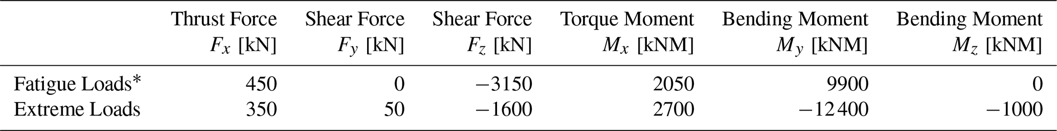
Coordinate system: x axis along the shaft axis toward the gearbox, z axis in the opposite direction of gravity; see Fig. 1.
∗ Damage equivalent loads interpolated for a gradient of 10.8 and a reference cycle number of 106.
3.2 MBU designs and power density analysis
The original MBU comprises a cast rotor shaft with a mass of 16.2 t, a non-locating 2.1 t cylindrical roller bearing on the rotor side (upwind) and a locating 0.9 t double-rowed tapered roller bearing on the gearbox side (downwind). To fasten the main bearings, assembly components with a total mass of 2.5 t are used. The bearing housings are combined into one cast frame, which is connected to the machine frame (see Fig. 1). The cast rotor shaft is made from EN-GJS-400-18 via a sand-casting process. The biggest wall thickness of the finished shaft is above 300 mm and therefore close to the technically feasible limit of iron casting (≈400 mm). Larger wall thicknesses increase the risks of material defects, possibly resulting in unusable parts. The use of permanent mould casting allows for a higher cooling rate, resulting in better material properties due to a finer grain structure. This enables larger wall thicknesses but is only used for large-series production due to the high metal mould costs. Sand casting requires a surface surcharge (allowance) of up to 50 mm, approximately 20 % of the shaft mass, and 10 % additional material for sprue and other material loses (Weiß, 2024). This ensures that the final geometry can be machined to the required tolerances from the cast/forged geometry. Therefore, the material input is estimated to be 21.3 t of cast iron.
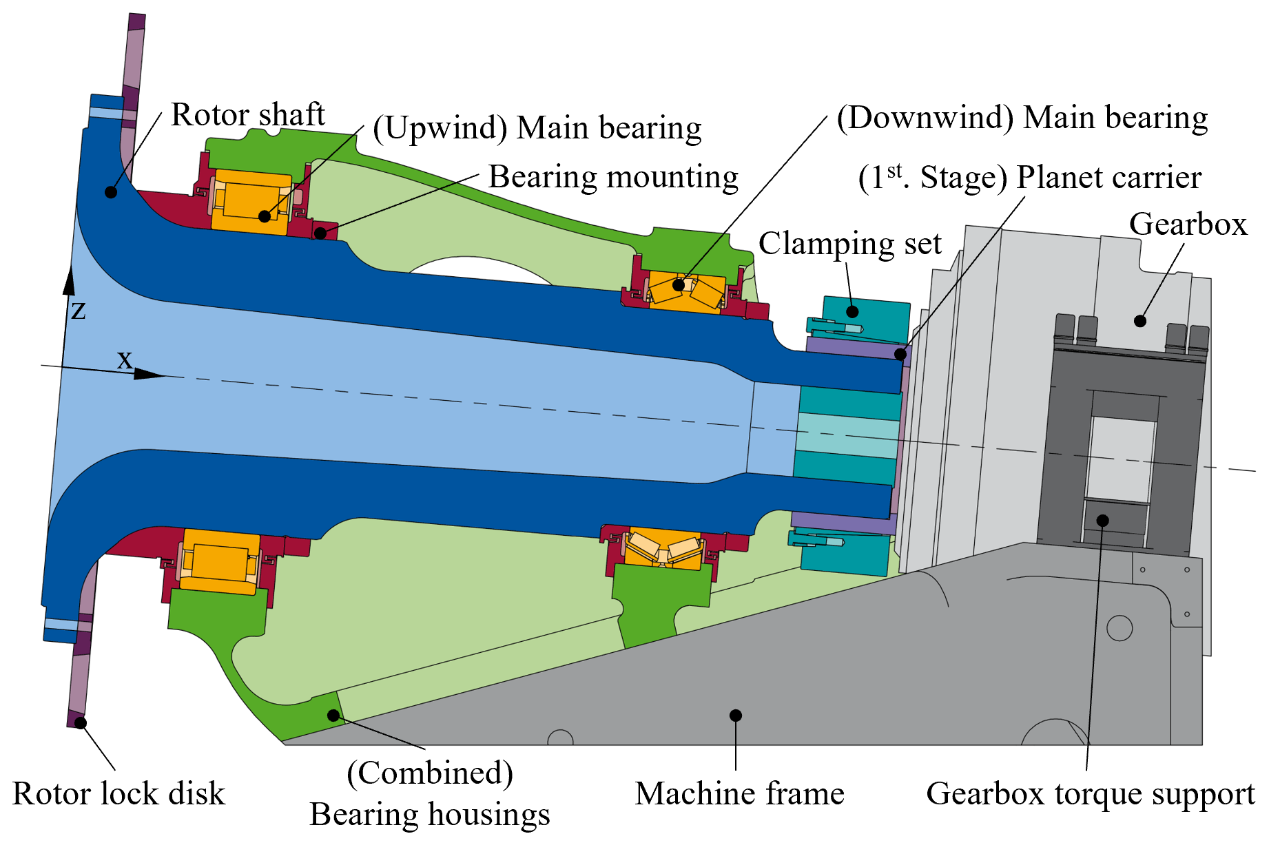
Figure 1Sketch of the maxcap141 MBU in a half-section view and adjacent components in full view.
For the case study comparing cast and AHD steel hollow-forged rotor shafts, two variants of the maxcap141 MBU are generated through the aforementioned MBU predesign tool in MATLAB (The MathWorks, Inc., 2023). This ensures that the design of both MBU variants has the same level of detail and underlying assumptions (e.g. loads, boundary conditions). The inputs include the fixed geometry of the original shaft (shaft length, flange diameter and thickness, hub flange screw connection) and shaft loads, among others. Both manufacturing processes induce restrictions on the shaft design. For example, casting can produce conical shaft segments, while hollow forging can only produce cylindrical shaft segments with a maximum diameter jump of 600 mm between segments.
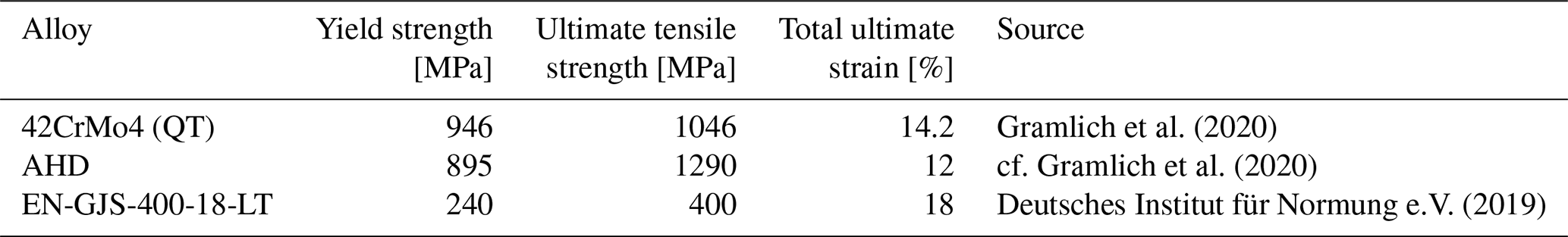
AHD steels are standardised and commercialised with a focus on small and medium die forging (material number 1.5132). To increase the hardening ability for larger wall thicknesses, modifications were developed alongside this study, and the resulting alloy is currently under thorough investigation regarding the tensile properties, Charpy V-notch toughness and fatigue resistance. Preliminary results show that boron, chromium and nickel can be used to further increase the air-hardening potential of AHD steels, enabling the production of components with wall thicknesses larger than 300 mm. The static material strength of the AHD steel alloy and cast iron used can be found in Table 2 in comparison to the standard QT-forging steel 42CrMo4. The fatigue strengths are derived from the static material properties via the German FKM guideline (see Forschungskuratorium Maschinenbau, 2020), including the reduction in material strength over the wall thicknesses. While the present study uses the FKM guideline, it is not directly applicable to AHD steels. As demonstrated previously (Schmiedl et al., 2020), AHD steels show cyclic hardening during the first load cycles (while standard steels experience cyclic softening), resulting in unused potential of AHD steels. At this stage, the potential cannot be considered due to a lack of data. Likewise, the cyclic hardening justifies the fact that no additional safety margin is required when deriving the fatigue strength through the FKM guideline. As the material properties are based on lab samples, broad testing is required before the alloy is used in WTs to ensure reliability.
Table 2Comparison of mechanical properties of cast and hollow-forged shaft materials.
The resulting rotor shaft geometries (predesign) and chosen bearings are shown in Figs. 2 and 3. Both rotor shaft designs are generated based on a structural integrity assessment using the FKM guideline. The degrees of utilisation of each rotor shaft (calculated via a finite-element analysis (FEA) using Abaqus; Dassault Systèmes Simulia Corp., 2021), the bearings (via DIN EN ISO 76 / 281) and the bearing angular misalignments (shaft bending via FEA) are shown in Figs. 4 and 5. As all degrees of utilisation are under 1, the shaft and bearings have sufficient load-bearing capacity for the chosen load cases; see Table 1. For main bearings, it is assumed that misalignment of the bearings due to shaft deflection can be compensated for by profiling the rolling elements. Therefore, the misalignment is not converted into a degree of utilisation. For spherical roller main bearings such as those selected here, the literature suggests a maximum allowable misalignment of 1.5–3° (Dykes et al., 2014). The radial deflection of the downwind shaft end is kept under 3 mm to ensure the assembly of the clamping set to the gearbox.
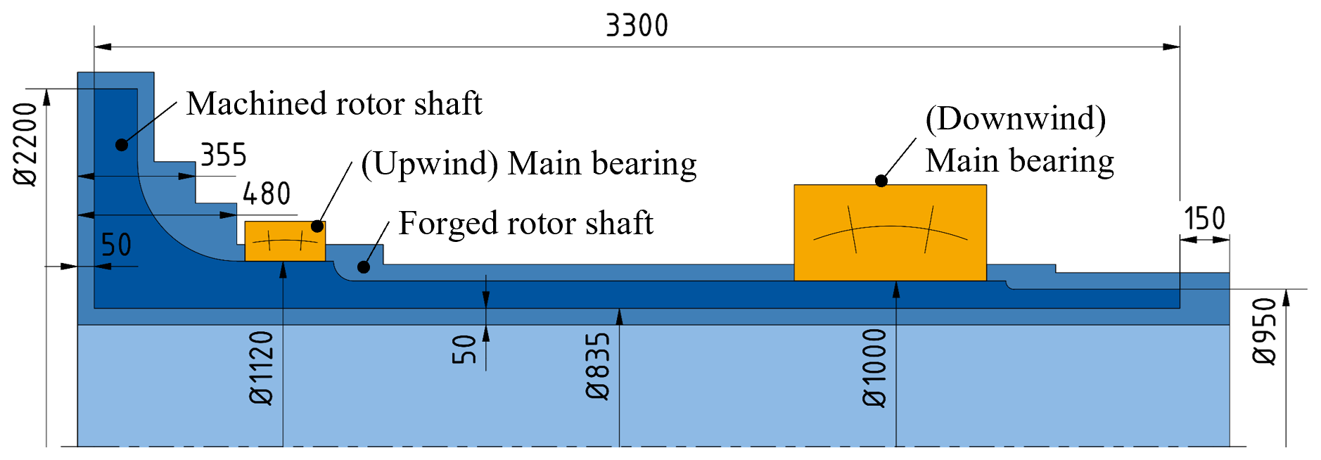
Figure 2Sketch of the hollow-forged rotor shaft and its forging geometry, together with the chosen main bearings.
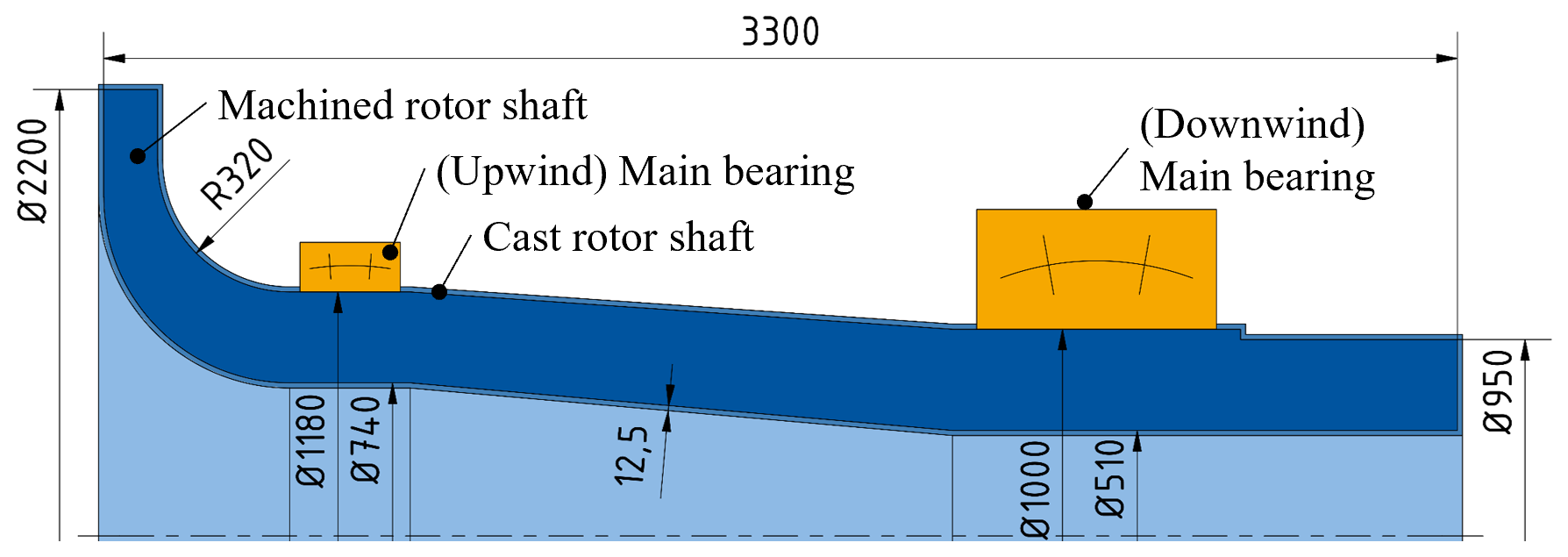
Figure 3Sketch of the cast rotor shaft and its casting geometry, together with the chosen main bearings.
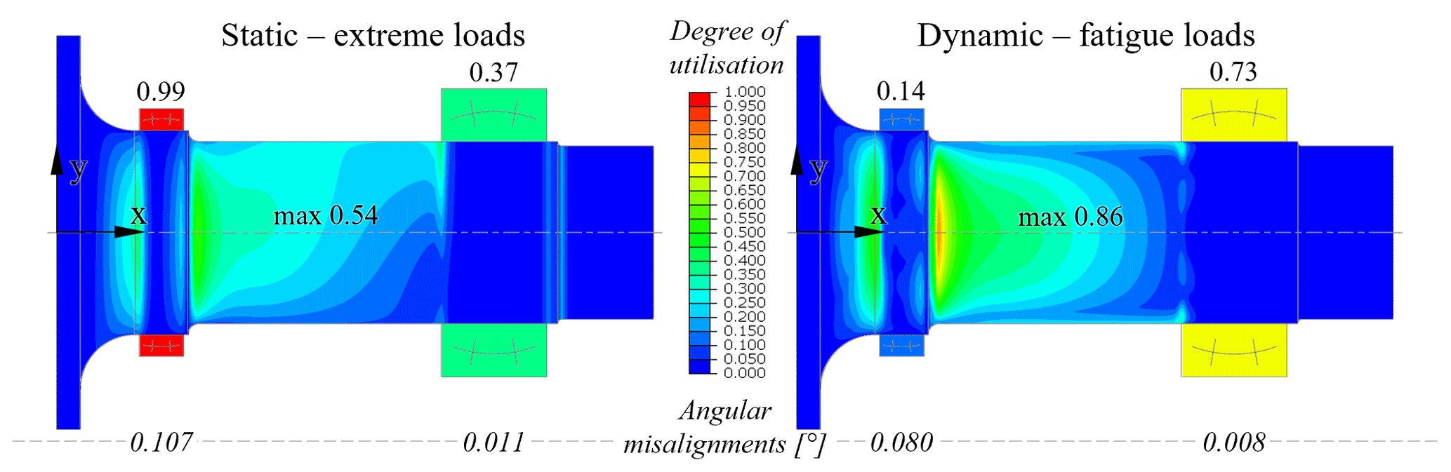
Figure 4Degrees of utilisation of the hollow-forged rotor shaft (FEA), main bearings (DIN EN ISO 76 / 281) and angular shaft misalignment (FEA).
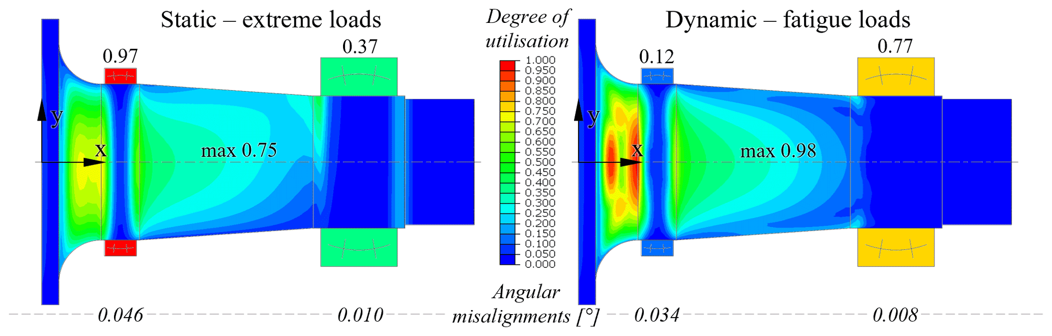
Figure 5Degrees of utilisation of the cast rotor shaft (FEA), main bearings (DIN EN ISO 76 / 281) and angular shaft misalignment (FEA).
The resulting hollow-forged rotor shaft has a mass of 10.2 t, and the upwind and downwind bearings have a mass of 0.78 and 4.38 t respectively; see Table 3. The mass of the bearing housings (including assembly components) is scaled based on the bearing masses using a factor of 2.92 taken from NREL's WISDEM/DrivetrainSE (Guo et al., 2015; National Renewable Energy Laboratory, 2024).
Table 3Mass comparison of the different MBU variant components.
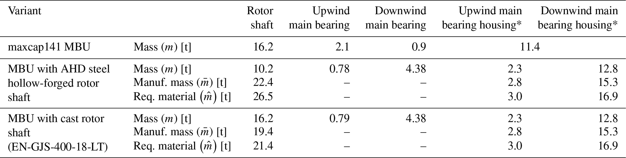
* Including main bearing assembly components.
When hollow forging the rotor shaft, the material flow along the shaft axis is harder to control than the change in diameter due to the free elongation. Therefore, forging needs larger surcharges in the axial direction than in the radial direction. For individual- or small-series production, surcharges are set larger to minimise the risk of forging errors. Large surcharges further reduce the achievable material strength of the forging part, as the material strength decreases for larger wall thicknesses, defined by the shaft geometry prior to heat treatment (Forschungskuratorium Maschinenbau, 2020). Hence, for AHD steel hollow-forged shafts, the post-forging geometry determines the material strength for the strength assessment. In comparison, standard QT steel parts allow a rough machining before heat treatment, which lowers the wall thicknesses but also increases the risk of scrap production due to heat treatment distortions.
Based on surcharges for small-series production – which were provided by the industry – the shaft geometry is extended by 150 mm axially and 50 mm radially, marked in Fig. 2. As the hub flange is forged first, its axial elongation is independent of the other shaft sections, allowing a reduction in surcharges to 50 mm axially, which greatly reduces the required forging material. The rounded flange transition is also forged with a 50 mm axial surcharge in two cylindrical steps, approximating the transition. The feasibility of the surcharges was verified via hollow-forging simulations in Forge NXT 4.0 (Transvalor S.A., 2023). Consequently, the (post-)forging mass of the shaft is 22.4 t, and, considering material losses during forging (see Sect. 3.3.1), around 26.5 t steel is required to produce the part.
In comparison, the cast rotor shaft has a mass of 16.2 t, and its upwind and downwind bearings are 0.79 and 4.38 t respectively; see Table 3. As the mass difference between the predesigned cast shafts and original cast shafts is less than 0.1 t, the predesign tool produces a realistic predesign. The casting mass and required material of the rotor shaft and bearing housings are estimated with the casting percentages above. For simplification, the surcharge is assumed to be evenly distributed, leading to a 12.5 mm machining allowance around the shaft. In reality, the surcharge would be focused on functional surfaces, such as the bearing seats or flange screw connection, while non-functional surfaces might keep the casting finish.
Unlike the maxcap141 variant, both predesign variants use spherical roller bearings (SRBs) as main bearings, as those offer a high load capacity and misalignment tolerance, enabling thinner shafts and therefore the highest power density of all catalogue bearings in this case. Both variants have similar bearing configurations, sharing the downwind spherical roller bearing and using a comparable spherical roller bearing upwind with a 60 mm inner diameter difference. The similarity is caused by the MBU predesign tool using a publicly available bearing catalogue from which main bearings are chosen. The problem is that the bearings found in catalogues are not evenly distributed but instead have increasingly larger jumps in inner diameter, with certain dimension series (ratio between inner diameter, outer diameter and width) missing for larger diameters. In the case of the downwind bearings, none of the smaller roller bearings are suitable for the given shaft diameter and load, while increasing the shaft outer diameter for a larger bearing would reduce the MBU power density. This results in an over-dimensioned downwind main bearing with a mass of 4.38 t compared to the original bearing with 0.9 t. Changing the locating bearing to the upwind position does not affect the bearing selection for the given MBU.
A comparison of the masses of both variants shows that for the stand-alone rotor shaft, the AHD steel hollow-forged shaft is 37 % lighter than the cast shaft, resulting in a 16.5 % lighter MBU. Converted into a power density metric, the cast MBU variant reaches 63.1 kW t−1, while the hollow-forged MBU variant reaches 75.6 kW t−1, corresponding to a 20 % increase in power transferred via each tonne of MBU mass. This showcases the potential of hollow-forged shafts in terms of power density. One significant drawback is that the production of the hollow-forged shaft needs 24 % more material than the cast shaft, affecting the manufacturing costs.
3.3 Manufacturing costs
To estimate and compare the manufacturing costs, a mass-dependent equation is derived for each MBU component or manufacturing process. Transport costs to the customer are excluded as these vary with the WT's location.
3.3.1 (Hollow-)forging manufacturing costs
For forged parts, Knight (1992) states that the material costs make up 50 % of the total manufacturing costs, with operating costs at 40 % and tooling costs (postprocessing) at 10 %. Considering that the AHD steel is hollow forged and air hardens (no heat treatment needed), Knight's correlation is adjusted to Eq. (3) to model forging (F) and hollow-forging (HF) shafts using internal and industry data:
The variable is the mass of material needed to (hollow) forge the shaft. It includes the surface surcharges that are mechanically removed during postprocessing, 1 % material loss due to scale (oxidation), 2 % material loss when the forging ingot is perforated for the mandrel and around 15 % unusable material at the forging block ends (raw material). As the forging-specific surcharges heavily depend on the shaft geometry, they cannot be incorporated via a fixed surcharge percentage as is done for casting. The factor fTC considers the relation between material costs (MCs) and total costs (TCs) and derives to 2. The term aHF takes the additional cost of hollow forging compared to solid forging into account. The 40 % operating costs are mainly driven by the energy costs of the forging process and can be split into 20 % forging and 20 % heat treatment. Assuming that hollow forging is 1.5 times as expensive as solid forging (e.g. additional costs of the mandrel), the 20 % forging operating costs increase to 30 %, corresponding to aHF of 0.1. Similarly, as the AHD steel air hardens, the 20 % heat treatment operating costs drop to 0 %, corresponding to a heat treatment (HT) term aHT of 0.2. To consider fluctuations in material, energy and labour prices, a spreading factor fS of 1.0 to 1.3 is included.
The material costs of the AHD alloy MCAHD and a 42CrMo4 QT steel MC42CrMo4 in comparison are estimated based on the trading price of (unalloyed) steel, their alloying elements and a processing cost factor; see Tables 4 and 5.
Table 4Steel and alloy element trading prices.
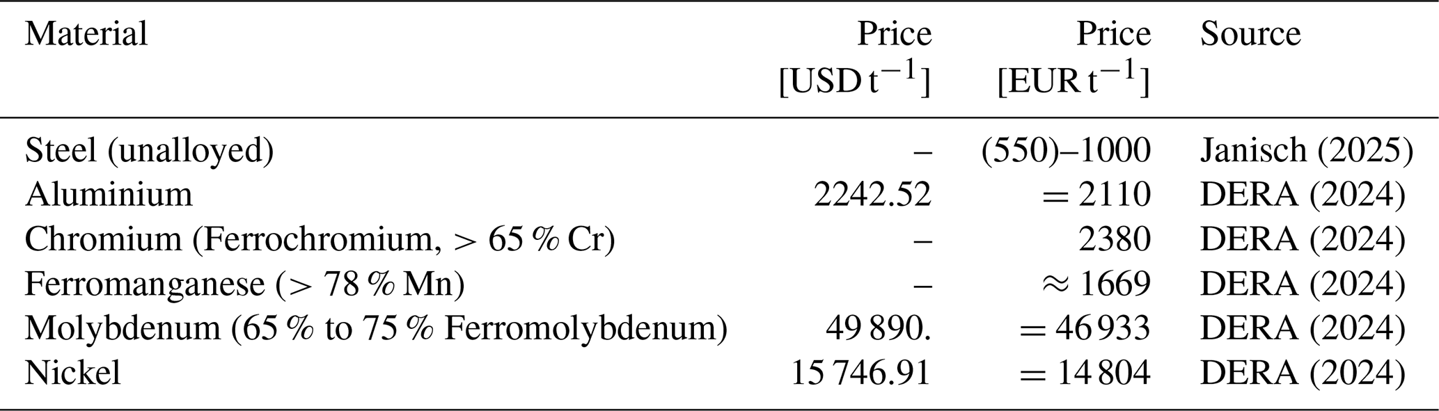
On average, EUR 1 exchanged for USD 1.0630 in November 2024 (Europäische Zentralbank, 2024). As ferromanganese is a pre-alloy, the price is corrected by the corresponding manganese content. The price of the other pre-alloys is already adjusted in the source.
Table 5Material price estimate of AHD alloy and 42CrMo4 QT steel.
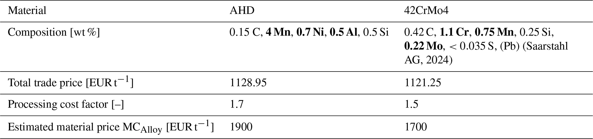
Only bolded elements are added during alloy making, influencing material prices.
The total trading price of each alloy is the sum of the added alloying elements and remaining steel content. A processing cost factor between 1.5 and 1.7 considers the additional process costs of creating (melting) the steel alloys and pouring it into a block form for forging. As AHD is a new steel alloy, its processing cost factor may be larger due to e.g. production line adjustments needed or use of nonstandard alloying elements.
Inputting all variables into Eq. (3), the resulting manufacturing costs of AHD steel hollow-forged rotor shafts can be estimated with Eq. (4), while Eq. (5) estimates a solid-forged rotor shaft from 42CrMo4 in comparison:
Comparing both equations might lead to the conclusion that a solid-forged shaft is cheaper than an AHD steel hollow-forged shaft. This is generally not the case, as a solid-forged shaft needs to be drilled out, leading to higher forging masses (surcharges) compared to a hollow-forged shaft. (A similar predesigned solid-forged 42CrMo4 rotor shaft with a 200 mm bore has a mass of 22.8 t and requires 37.5 t material.) The estimated higher material costs of AHD steel and higher operating costs of hollow forging are mostly compensated for via the omission of the heat treatment process.
3.3.2 Casting manufacturing costs
The manufacturing costs of the cast shaft are estimated using Eq. (6) for EN-GJS-400-18-LT or EN-GJS-500-14 depending on the size and complexity of the cast component:
The cost is based on either the mass of the final shaft (mShaft) – material surcharges for postprocessing (machining, ≈20 % of the shaft mass) and casting losses (≈10 % of the raw shaft mass) already included via fixed factors – or the required material mass for casting (). The equation is based on the cost estimation of the cast hub (Reichartz et al., 2024). Adjusting the manufacturing parameters for the cast rotor shaft and using industry feedback results in Eq. (6). To better compare the costs to the hollow-forged rotor shaft, a cost range is given. Shafts that are harder to manufacture (larger wall thicknesses, higher material grades) lie in the upper price range.
3.3.3 Main bearing housing manufacturing costs
The costs of the main bearing housings (index H, including assembly components) are given by Eq. (7), assuming that the specific cost of the non-cast assembly components is comparable to the cost of the cast housing:
The equation is similarly based on Reichartz et al. (2024). As the housing design requirements are simpler, the manufacturing is less challenging and therefore cheaper.
3.3.4 Main bearing manufacturing costs
Cost estimations of WT main bearings (index B) vary greatly between sources. Malcolm and Hansen (2006) estimated a specific cost of USD 17 600 t−1 in 2002, which equals around EUR 28 000 t−1 today.1 Reichartz et al. (2024) indicate specific costs of EUR 1800 t−1, split into 45 % material prices (SAE 52100/100Cr6 for rolling elements) and 55 % production costs (Harzendorf et al., 2018). Buying single main bearings, the costs can reach up to EUR 30 000 t−1 due to a lack of quantity discounts and main bearings mostly being custom-made. Averaging the literature values, a specific cost of EUR 25 000 t−1 is assumed; see Eq. (8):
3.3.5 Manufacturing cost comparison
The resulting cost of the components are listed in Table 6, with component costs being rounded to the nearest EUR 10 000.
Table 6Cost estimation of the two predesigned MBU variants.
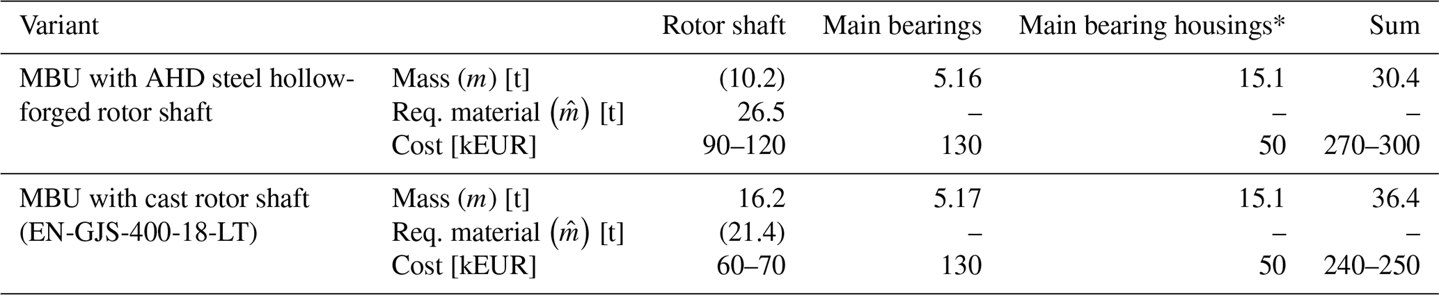
*Including main bearing assembly components. Values in brackets are not used for cost estimations.
As the main bearings of the two examined MBU variants are nearly identical, their cost difference is negligible. The same applies to the main bearing housings and included assembly components. The AHD steel hollow-forged rotor shaft (EUR 90 000–120 000) is EUR 30 000 to 50 000 more expensive than the cast rotor shaft (EUR 60 000–70 000). Even when considering cost savings from a higher power density within the drive train, enabling thinner tower designs and reducing logistic costs, the AHD steel hollow-forged rotor shaft is not economical yet. This is caused by the extremely large amount of material required to manufacture the hollow-forged shaft, with a total manufacture surcharge of 160 % compared to 32 % for casting. The AHD steel itself does not affect manufacturing costs as much, as the additional costs of the alloy compared to a standard QT steel like 42CrMo4 are presumably small. Furthermore, hollow forging depends on the AHD steel, enabling a homogeneous hardening of the shaft cross section and offering comparable material strengths to QT steel while omitting heat treatment costs.
For the upper manufacturing costs to be comparable between casting and AHD hollow forging, the total hollow-forging surcharge needs to drop to 50 % (lower manufacturing costs 70 %), which equals postprocessing surcharges of 42 % (59 %) (calculated by setting the shaft cost equal and solving for forging surcharges). This is due to hollow forging having higher manufacturing costs relative to the shaft mass compared to casting but enabling lighter rotor shaft designs. A possible way to reduce the forging mass is a local optimisation of forging surcharges. To avoid forging errors, smaller surcharges require a precise understanding and control of the material flow at each forging step, ensuring that a forging geometry slightly larger than the final shaft geometry is formed. By upsetting (compressing) the entire shaft in the axial direction between the forging steps, the flange area can be straightened. This reduces the surcharges required to compensate for the funnel-shaped collapsing flange areas, thus significantly reducing the masses in this area. Material surcharges inside the shaft can be further reduced by using special mandrels or using the forging surface as is.
3.4 Manufacturing global warming potential
Like the manufacturing costs, mass-based formulas for the manufacturing GWP are derived using industry averages and feedback, including transportation emissions of a fixed travel distance.
3.4.1 Hollow-forging and AHD steel material emissions
The estimation of the hollow-forging GWP is based on a product carbon footprint (PCF) calculation of the predesigned hollow shaft, provided by the forge Dirostahl (Karl Diederichs GmbH & Co. KG, 2025) using the carbon footprint calculator FRED (FRED GmbH, 2024); see Table 7. As the raw emissions of AHD steel alloy are unknown due to insufficient production runs, the raw emission of a 42CrMo4 forging block is used instead. It is assumed that both steel alloys have similar raw emissions based on feedback from the steel manufacturer Georgsmarienhütte GmbH (2025), who also provided the raw emission values and AHD samples. As forging blocks are provided with discrete masses, a 40 t block is utilised in proportion to the required forging mass.
Table 7Product carbon footprint of a hollow-forged rotor shaft (Karl Diederichs GmbH & Co. KG, 2025).
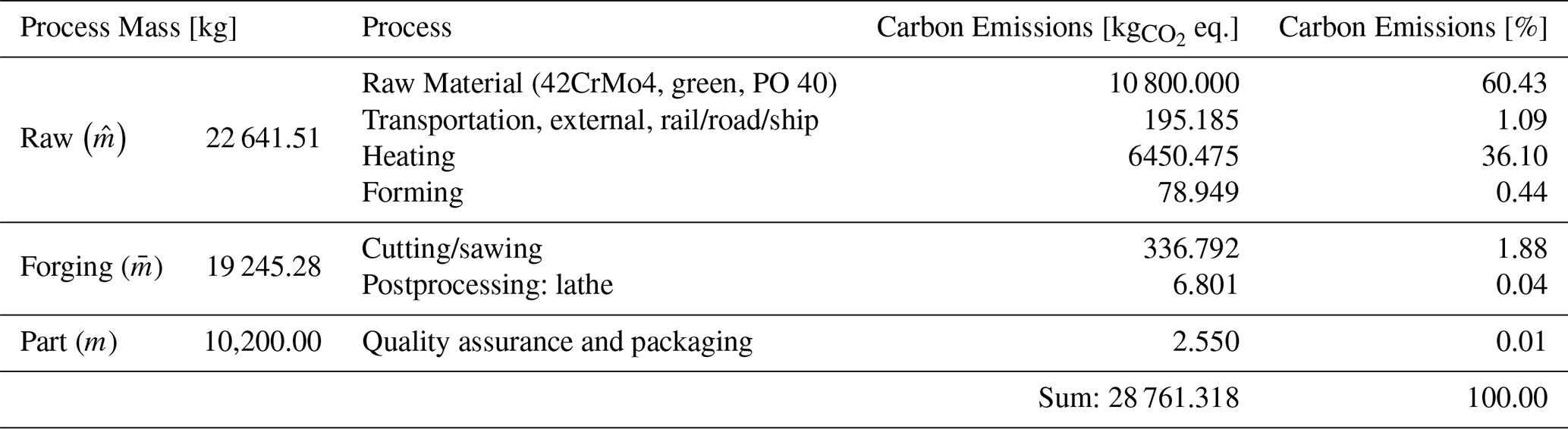
Raw steel can be divided into grey (standard) and green steel grades (reduced GWP). Using the raw material emission from Table 7, a specific emission value of 0.48 is set for AHD (green steel grade). The forging process starts with the raw mass and ends with the forging mass, as the forging block ends (≈15 %) are removed and material is lost (1 % oxidation, 2 % punching). The forging-process emissions (heating and forming) therefore mainly scale with the raw mass, resulting in a specific process emission value of 0.29 . After forging, the forging mass is reduced to the part mass using mechanical postprocessing (cutting/sawing of ends and turning of the shaft), with a specific postprocessing emission of 0.038 . Given the air hardening of AHD steel, no GWPs arise for heat treatment. As the transport emissions between the steel manufacturer and forge change for each forge, they are omitted for this comparison. The same applies to the quality assurance and packaging, which are also negligibly small. The total GWP estimation for (green) AHD steel hollow forging is given in Eq. (9):
Using grey steel from the same steel manufacturer, the raw material emissions double to 0.96 or reach 0.56 for an in-between grade. The reduction in GWP of the green steel grade is achieved via carbon-neutral coke (biocarbon) and green electricity usage, which makes the green steel grade approximately EUR 30 t−1 more expensive than the grey steel grade (Georgsmarienhütte GmbH, 2025), which increases costs by 1 % or 2 %. Given that the scattering in manufacturing costs is larger than the additional costs of a green steel grade, the price increase is neglected.
The ratio between raw material, forging process and postprocessing emissions depends on the surcharges assumed. For the predesigned AHD hollow-forged rotor shaft, around 60.9 % of total emissions come from the raw material, around 36.8 % from process emissions and 2.2 % from postprocessing emissions (machining).
3.4.2 Casting emissions
To estimate the casting emissions for the rotor shaft and main bearing housings (included assembly components simplified as additional casting mass), the GWP of the raw materials (see Table 8), the casting process and the mechanical postprocessing are combined.
Table 8German foundry average global warming potential of different casting raw materials (FRED GmbH, 2024).
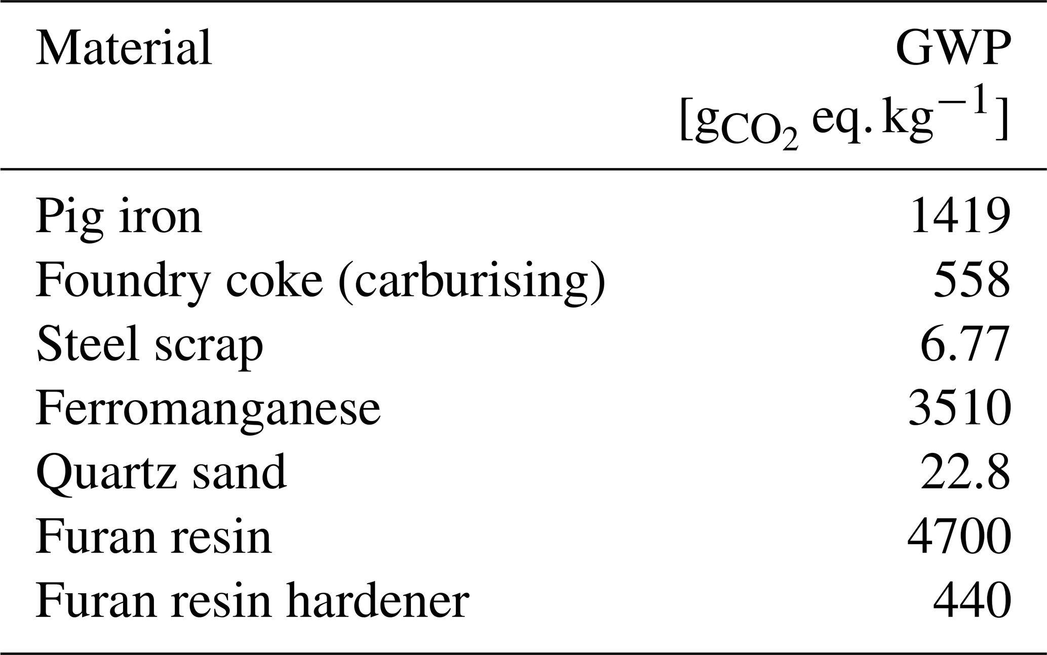
It is assumed that the EN-GJS-300-18-LT cast iron is mixed from 0.32 % ferromanganese (equals 0.25 % manganese (Teutoguss GmbH, 2024) with a manganese content of 78 % (DERA, 2024)), 2 % foundry coke for carburising (cf. James Durrans GmbH, 2025) and the rest as scrap steel/cast iron (cf. Abdelshafy et al., 2023). This combines to a GWP for cast iron of 0.31 , with lower scrap content increasing raw material emissions. As metal moulds are only used for large series of parts, a resin sand-casting process is taken as the basis. The sand mix is estimated to be 1.2 % furan resin, 0.6 % hardener and 98.2 % quartz sand (cf. Vu, 2025). As (quartz) sand has a reuse rate larger than 95 % (Förder- und Anlagentechnik GmbH, 2013), the material emission of resin sand calculates to 0.06 . The amount of sand needed to cast a part heavily depends on the part's geometry and pit size. A ratio of 1 t resin sand per tonne cast iron is assumed (around four to one volume ratio). The casting process itself is mostly electrified (in Europe), with a total electricity demand of 1150 kWh t (Weiß, 2024). This value not only includes direct casting processes like the smelting of the iron but also auxiliary processes, e.g. part cleaning and sand recycling. The average electricity mix for the German foundry industry has a GWP of 0.491 kg eq. kWh−1 (FRED GmbH, 2024), similar to the general German electricity mix. The casting process therefore produces around 0.57 . The emissions created during postprocessing of the cast part to the final geometry (turning/milling) mainly depend on the hardness and strength of the material. For an EN-GJS-400-18-LT, an energy demand of 107.5 kWh t is assumed, equalling 0.053 Chip with the above-used electricity mix. The value is based on the CoroPlus®ToolGuide, calculating the energy needed for external-longitudinal turning per chip mass on a 200 kW universal lathe, and is independent of the outer shaft diameter (AB Sandvik Coromant, 2011). Equation (10) combines all casting emissions into one formula:
For the given surcharges, around 33 % of the emissions stem from the casting material itself, 6.4 % from the resin sand mould, 59.8 % from the casting process (including auxiliary processes) and 0.8 % from the mechanical postprocessing. As cast iron reaches its desired material properties during cooling, no heat treatment emissions arise.
3.4.3 Bearing manufacturing emissions
The GWP of a main bearing mainly results from the raw material, forging, heat treatment, turning and grinding. Schaeffler AG (2024b) states in its sustainability report that the PCF of a large tapered roller bearing for WTs could be reduced by 70 % to 1.5 via the use of green steel, higher material utilisation and induction hardening. As the use of green bearings is not widespread, the original carbon emission of 5 is used for the emission comparison; see Eq. (11). Available main bearings found in the EasyCalc database show comparable emission values (Schaeffler AG, 2024a).
3.4.4 Transportation emissions
The emissions during transportation scale with the mass of the parts and distance travelled. FRED lists average emission values for different means of transportation; see Table 9.
Table 9Transport emissions for different means of transportation (FRED GmbH, 2024).
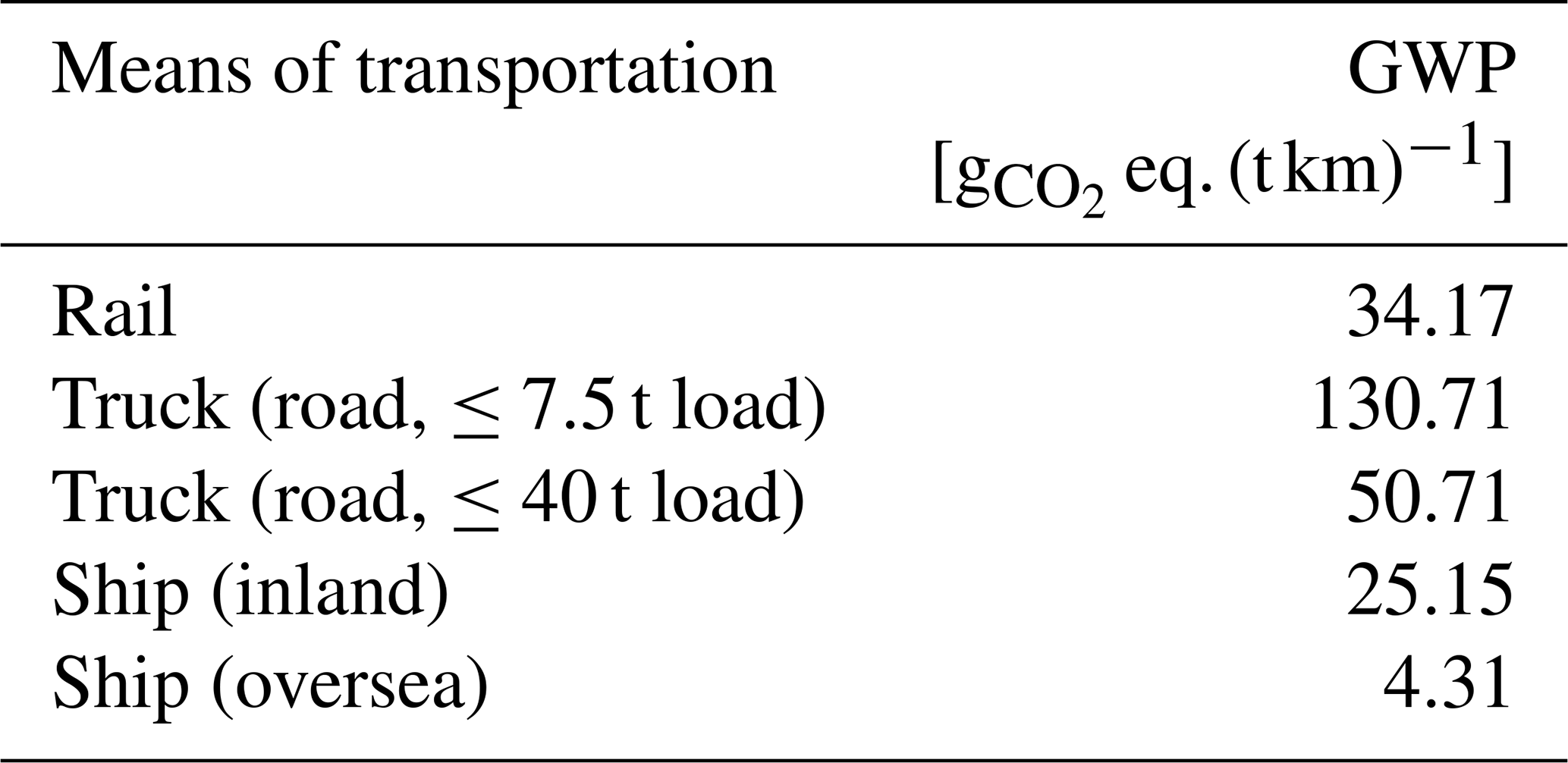
As the transport distance depends on the manufacturing and installation sites, a fixed distance of 1000 km by truck (≤40 t load) is included into the emission comparison, resulting in Eq. (12). Overseas transportation is not considered, as all components are assumed to be manufactured and installed in Europe.
3.4.5 Manufacturing GWP comparison
The individual and combined GWPs of all components are listed for both MBU variants in Table 10.
Table 10Manufacturing-based GWP estimation of the two predesigned MBU variants.
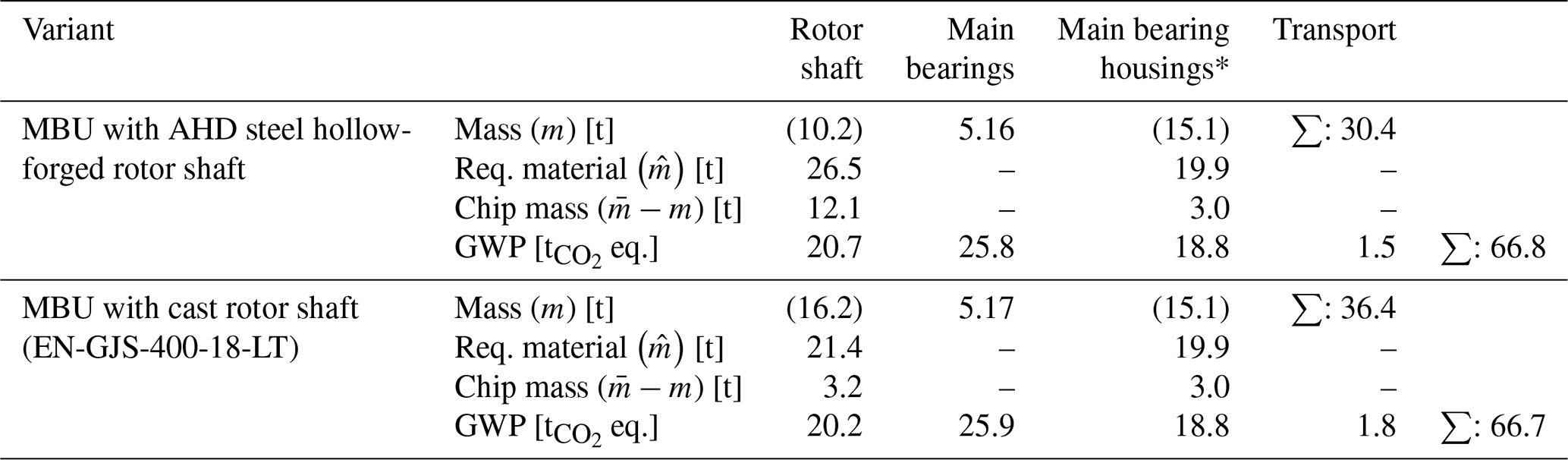
* Including main bearing assembly components. Values in brackets are not used for GWP estimations.
The emissions of the cast rotor shaft are 2.5 % smaller than for the hollow-forged shaft (20.2 vs. 20.7 ). Hollow forging with green steel has double the raw material emissions compared to casting but half the specific process emissions. Cast iron is made from mostly low-emission scrap metal and directly cast into the mould. In contrast, forging steel is cast into a block form at the steel mill and reheated for forging, requiring more energy in total. For the given shaft predesigns, the hollow-forged shaft needs around 15 % more material than the cast shaft. The resulting higher GWP is offset by the GWP difference in the primary energy sources, with fossil gas used in forging having on average 45 % less emissions than electricity used in casting (German gas mix 2024: 220.67 , German foundry electricity mix 2023: 491 , German electricity mix 2023: 498 ; FRED GmbH, 2024). As the German electricity mix is still based on 16.2 % lignite, 5.4 % black coal and 15.8 % fossil gas (BDEW Bundesverband der Energie- und Wasserwirtschaft e.V., 2024), it has a relatively large GWP. As hollow forging has higher machining surcharges, the postprocessing emissions are 170 % higher than for casting but make up only 2.2 % of total hollow-forging emissions and 0.8 % of total casting emissions, respectively (transport excluded). Although (air-hardened) AHD steel has a higher material strength and hardness than cast iron, the specific postprocessing emissions of hollow forging are 28 % lower compared to casting, as the shaft ends of the hollow-forged shafts are sawn off. This reduces the real chip volume, therefore lowering the energy required. By omitting the heat treatment process for AHD steel, emissions comparable to the emissions of the forging process are saved, as a QT process would require additional heat cycles.
The calculation of GWPs heavily depends on the assumption and scope considered. For example, increasing the pig iron content in cast iron increases the GWP of casting, resulting in higher emissions than hollow forging. The GWP calculation performed should therefore be considered a method rather than hard facts, and a recalculation is advised when better assumptions/values are available. Considering that the EU wants to become climate neutral by 2050 (see Directorate-General for Climate Action, 2019), the future GWP of both MBU variants depends on how much each manufacturing process and component manages to reduce emissions. For casting, GWP will depend on switching to climate-neutral electricity and further increasing the scrap content. In comparison, the forging industry also needs to substitute fossil gas used for heating with climate-neutral alternatives like electric furnaces, green hydrogen or green gases.
This work presents a case study comparing MBUs with AHD steel hollow-forged and cast rotor shafts, comparing power density, manufacturing costs and manufacturing carbon emissions, summarised in Fig. 6. Based on the MBU of a 2.3 MW reference WT, one MBU variant for each rotor shaft was predesigned, ensuring comparability. The resulting AHD steel hollow-forged rotor shaft has a mass of 10.2 t, which is 37 % lower than the cast shaft (16.2 t) or 16.5 % lighter considering the whole MBU (30.4 vs. 36.4 t). For the current predesign, hollow forging the rotor shaft requires 26.5 t AHD steel, which is 24 % more material than needed for the cast shaft (EN-GJS-400-18-LT). This is due to the conservative forging surcharges (allowance) assumed (160 % in total compared to 32 % for casting).
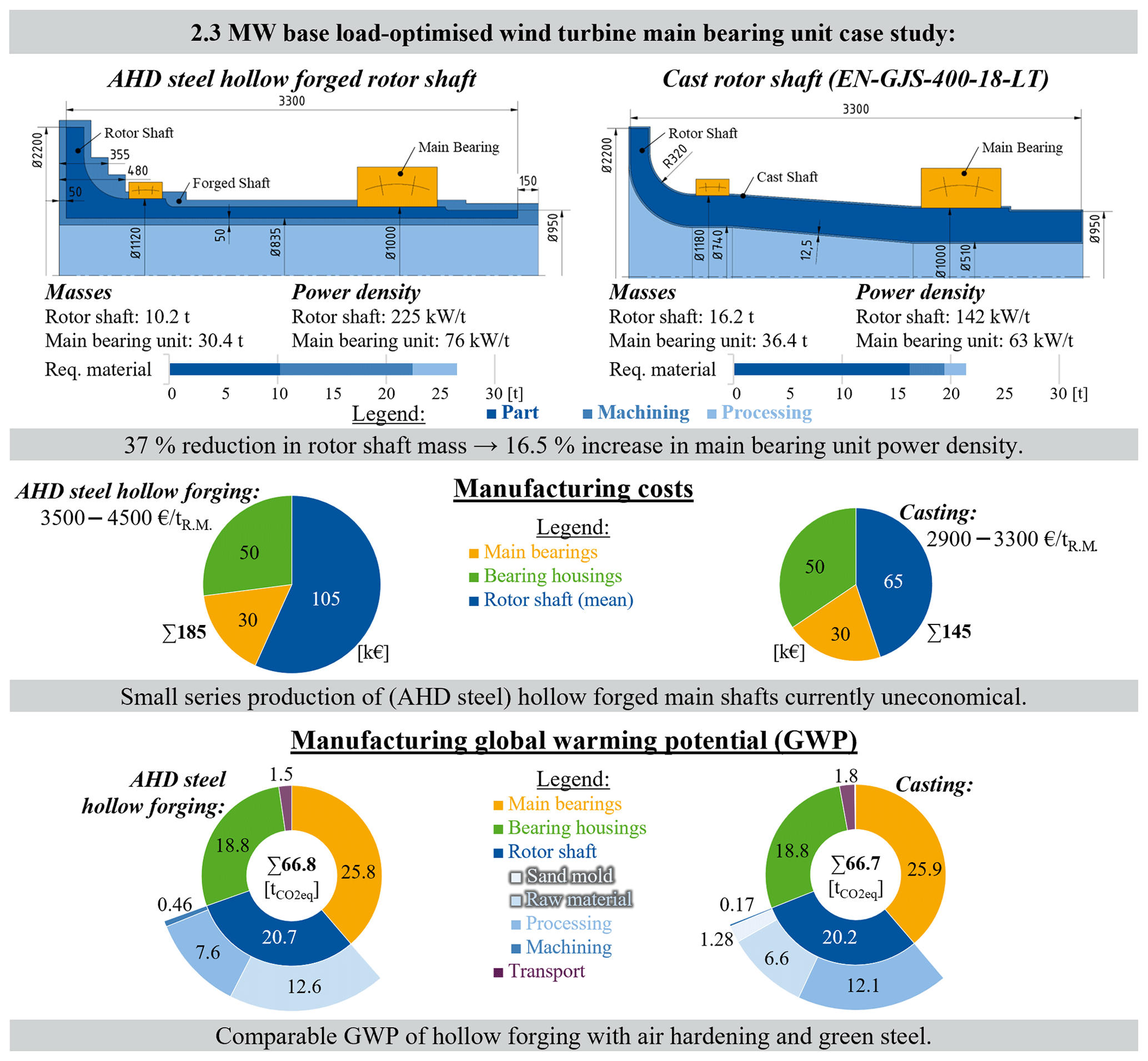
Figure 6Case study summary: comparison of power density, manufacturing costs and manufacturing GWP of MBUs with cast and AHD steel hollow-forged rotor shafts.
Consequently, the hollow-forged shaft is EUR 30 000 to 50 000 (50 %–70 %) more expensive than the cast shaft (EUR 90 000–120 000 vs. EUR 60 000–70 000), assuming a hollow-forging price of EUR 3500 to 4500 per tonne of required material for the AHD steel. For forging to become cost comparable to casting, total forging surcharges need to be reduced from currently 160 % to around 50 % of the final shaft mass. Smaller forging surcharges become possible for example with better material flow control (e.g. through optimisation by means of forging simulations) or larger-series productions for better risk management.
The omission of the heat treatment process for AHD steel and the use of a green steel grade make the GWP of hollow forging comparable to casting (casting: 20.2 vs. hollow forging: 20.7 t eq.). The GWP of casting heavily depends on the ratio of scrap metal and pig iron, as well as the electricity mix used. For hollow forging, a reduction in GWP is achievable with lower forging surcharges, which lower the required mass, and by switching to GWP-neutral energy sources for heating. Nonetheless, as AHD steel air hardens, it is already more sustainable than forged parts from QT steels like 42CrMo4, as they have similar raw material emissions and require an additional heat treatment process.
The main bearings and bearing housings currently make up more than two-thirds of the total MBU GWP. Using lighter, non-catalogue main bearings or switching to greener manufacturing processes therefore directly reduces GWP. The reduction potential of hollow-forging surcharges will be analysed in the ongoing HoRo-LHD project and further works. As (AHD steel) hollow forging and (sand) casting both have limits regarding the largest manufacturable wall thickness, it is also necessary to consider the wall thickness in the economic viability analysis for larger rotor shafts. This also relates to the selection of main bearings for larger rotor shafts. To maximise power density, the main bearings and rotor shaft must be adjusted to each other (e.g. choosing a larger, heavier bearing, which enables mass reduction of the rotor shaft via a larger inner diameter/section modulus). As this study used a publicly available bearing catalogue, both MBU variants ended up with a nearly identical bearing configuration. A larger, finer and evenly distributed bearing database would extend the solution space for MBUs, leaving more adjustment potential for the different rotor shaft manufacturing methods.
No raw data were used in this work. Calculations (spread sheets, codes) can be provided by the corresponding author upon request. The release of unpublished industry data (e.g. PCFs) must be approved beforehand.
The predesign tool used can be provided by the corresponding author upon request (coded in MATLAB R2023b in German), excluding unpublished industry data used as predesign inputs.
AG, VZ and NR conceptualised the work and underlying research project; CH, MG and AG developed the methodology for the case study; CH wrote the manuscript draft, for which MG added parts regarding hollow forging and AG regarding material engineering; GJ, DB, JR and AG supervised the research project as institute heads/chief engineers; GJ, DB and JR reviewed the manuscript draft.
The contact author has declared that none of the authors has any competing interests.
Publisher's note: Copernicus Publications remains neutral with regard to jurisdictional claims made in the text, published maps, institutional affiliations, or any other geographical representation in this paper. The authors bear the ultimate responsibility for providing appropriate place names. Views expressed in the text are those of the authors and do not necessarily reflect the views of the publisher.
The work presented is part of the project AVIF A 329 HoRo-LHD. The project investigates the feasibility of manufacturing hollow-forged rotor shafts using air-hardening ductile (AHD) steels.
The underlying project was funded by the nonprofit foundation Stiftung Stahlanwendungsforschung (im Stifterverband für die Deutsche Wissenschaft e.V.). The research institute further received a donation from the Forschungsvereinigung der Arbeitsgemeinschaft der Eisen und Metall verarbeitenden Industrie e.V. (AVIF) research association for the research project.
This open-access publication was funded by the RWTH Aachen University.
This paper was edited by Amir R. Nejad and reviewed by two anonymous referees.
AB Sandvik Coromant: CoroPlus®ToolGuide, AB Sandvik Coromant [software], http://www.sandvik.coromant.com/de-de/tools/coroplus-toolguide (last access: 20 January 2025), 2011.
Abdelshafy, A., Franzen, D., Mohaupt, A., Schüssler, J., Bührig-Polaczek, A., and Walther, G.: A Feasibility Study to Minimize the Carbon Footprint of Cast Iron Production While Maintaining the Technical Requirements, J. Sustain. Metall., 1, 249–265, https://doi.org/10.1007/s40831-022-00642-5, 2023.
BDEW Bundesverband der Energie- und Wasserwirtschaft e.V. (Ed.): Die Energieversorgung 2024 – Jahresbericht, http://www.bdew.de/service/publikationen/jahresbericht-energieversorgung/ (last access: 13 January 2025), 2024.
Dassault Systèmes Simulia Corp.: Abaqus/CAE, Dassault Systèmes Simulia Corp. [software], http://www.3ds.com (last access: 17 January 2025), 2021.
Deutsche Rohstoffagentur (DERA) in der Bundesanstalt für Geowissenschaften und Rohstoffe (Ed.): Preismonitor: November 2024, http://www.deutsche-rohstoffagentur.de/DERA/DE/Produkte/Rohstoffpreise/Preismonitor/preismonitor_node.html (last access: 15 January 2025), 2024.
Deutsches Institut für Normung e.V.: DIN EN 1563: Gießereiwesen – Gusseisen mit Kugelgraphit; Deutsche Fassung EN 1563:2018, https://doi.org/10.31030/2792445, 2019.
Directorate-General for Climate Action: Going climate-neutral by 2050: A strategic long-term vision for a prosperous, modern, competitive and climate-neutral EU economy, European Union, https://doi.org/10.2834/02074, 2019.
Dykes, K., Resor, B., Platt, A., Guo, Y., Ning, A., King, R., Parsons, T., Petch, D., and Veers, P.: Effect of Tip-Speed Constraints on the Optimized Design of a Wind Turbine, https://doi.org/10.2172/1159782, 2014.
Euler, J., Jacobs, G., Loriemi, A., Jakobs, T., Rolink, A., and Röder, J.: Scaling Challenges for Conical Plain Bearings as Wind Turbine Main Bearings, Wind, 4, 485–495, https://doi.org/10.3390/wind3040027, 2023.
Europäische Zentralbank: Euro-Referenzkurs der EZB / 1 EUR = … USD / Vereinigte Staaten, Zeitreihenschlüssel: BBEX3.M.USD.EUR.BB.AC.A02, http://www.bundesbank.de/dynamic/action/de/statistiken/zeitreihen-datenbanken/zeitreihen-datenbank/723452/723452?listId=www_sdks_b01012_2&tsTab=0&dateSelect=2023&tsId=BBEX3.M.USD.EUR.BB.AC.A02&startDate=2021&id=0 (last access: 15 January 2025), 2024.
Förder- und Anlagentechnik GmbH: Regenerierung von Altsanden, GIESSEREI – Die Zeitschrift für Technik, Innovation und Management, 11/2013, 92, available at: http://www.f-a-t.de/fileadmin/user_upload/18_Artikel.Thermische.dt.11.2013_de.pdf (last access: 20 January 2025), 2013.
Forschungskuratorium Maschinenbau e.V. (Ed.): Rechnerischer Festigkeitsnachweis für Maschinenbauteile aus Stahl, Eisenguss- und Aluminiumwerkstoffen: FKM-Richtlinie, 7., überarbeitete Ausgabe, VDMA Verlag, Frankfurt am Main, 45 1230 pp., ISBN 9783816307433, 2020.
FRED GmbH: FRED Carbon Footprint Calculato, FRED GmbH [software], http://www.app.fred-footprint.de (last access: 10 October 2024), 2024.
Georgsmarienhütte GmbH: Product Carbon Footprint (PCF) Vergleich, 2025.
Gramlich, A., Schmiedl, T., Schönborn, S., Melz, T., and Bleck, W.: Development of air-hardening martensitic forging steels, Materials Science and Engineering: A, 784, https://doi.org/10.1016/j.msea.2020.139321, 2020.
Gramlich, A., Hagedorn, W., Greiff, K., and Krupp, U.: Air Cooling Martensites – The Future of Carbon Neutral Steel Forgings?, Adv. Eng. Mater., 15, https://doi.org/10.1002/adem.202201931, 2023.
Gramlich, A., Helbig, C., Schmidt, M., and Hagedorn, W.: A comprehensive design approach to increase the performance of steels under minimal costs and environmental impacts, Sustainable Materials and Technologies, 41, e01040, https://doi.org/10.1016/j.susmat.2024.e01040, 2024.
Guo, Y., Parsons, T., King, R., Dykes, K., and Veers, P.: Analytical Formulation for Sizing and Estimating the Dimensions and Weight of Wind Turbine Hub and Drivetrain Components, National Renewable Energy Laboratory, Technical Report NREL/TP-5000-63008 https://doi.org/10.2172/1215033, 2015.
Hagedorn, W., Gramlich, A., Greiff, K., and Krupp, U.: Alloy and process design of forging steels for better environmental performance, Sustainable Materials and Technologies, 34, https://doi.org/10.1016/j.susmat.2022.e00509, 2022.
Harzendorf, F., Azzam, B., Schelenz, R., and Jacobs, G.: Manufacturing cost – a critical evaluation criteria for new developments in wind turbine drivetrain technologies, J. Phys. Conf. Ser., 1102, 12024, https://doi.org/10.1088/1742-6596/1102/1/012024, 2018.
Hollas, C., Jacobs, G., Züch, V., Röder, J., Reinisch, N., Gouverneur, M., Bailly, D., Babashahi, M., and Gramlich, A.: Power Density Analysis of Wind Turbine Main Bearing Units by Holistic Optimization of Material, Manufacturing and Design of the Main Shaft, J. Phys. Conf. Ser., 8, 82003, https://doi.org/10.1088/1742-6596/2767/8/082003, 2024.
CoinNews Media Group LLC: Inflation Calculator, http://www.usinflationcalculator.com (last access: 24 October 2024), 2024.
James Durrans GmbH: Aufkohlungsmittel, http://www.durransgroup.com/de/produkte/aufkohlungsmittel (last access: 17 March 2025), 2025.
Janisch, A.: Stahlpreisentwicklung 2025 – Stahlpreise weiterhin auf niedrigem Niveau, http://www.jactio.com/stahlpreisentwicklung-aktuell/ (last access: 4 March 2025), 2025.
Karl Diederichs GmbH & Co. KG (Ed.): Product Carbon Footprint: Grey Steel (42CrMo4, GMH PO40), 2025.
Knight, W. A.: Simplified early cost estimating for hot-forged parts, Int. J. Adv. Manuf. Technol., 3, 159–167, https://doi.org/10.1007/BF02601619, 1992.
Krause, A.: Research Projects “MaxCap” and “Validierung MaxCap”, http://www.cwd.rwth-aachen.de/cms/CWD/Forschung/Abgeschlossene-Projekte/~bakxck/Validierung-MaxCap/lidx/1/ (last access: 24 March 2025), 2024.
Kwon, Y. C., Kang, J. H., and Kim, S. S.: Study on Manufacturing Process of Hollow Main Shaft by Open Die Forging, Transactions of the Korean Society of Mechanical Engineers A, 2, 221–227, https://doi.org/10.3795/KSME-A.2016.40.2.221, 2016.
Malcolm, D. J. and Hansen, A. C.: WindPACT Turbine Rotor Design Study: June 2000–June 2002 (Revised), National Renewable Energy Lab. (NREL), Golden, CO (United States), NREL/SR-500-32495, https://doi.org/10.2172/15000964, 2006.
Manwell, J. F., McGowan, J. G., and Rogers, A. L.: Wind Energy Explained, Wiley, ISBN 978-0-470-01500-1, 2009.
National Renewable Energy Laboratory: WISDEM: Wind-Plant Integrated System Design and Engineering Model, National Renewable Energy Laboratory [code], http://www.github.com/WISDEM (last access: 17 January 2025), 2024.
Nejad, A. R., Keller, J., Guo, Y., Sheng, S., Polinder, H., Watson, S., Dong, J., Qin, Z., Ebrahimi, A., Schelenz, R., Gutiérrez Guzmán, F., Cornel, D., Golafshan, R., Jacobs, G., Blockmans, B., Bosmans, J., Pluymers, B., Carroll, J., Koukoura, S., Hart, E., McDonald, A., Natarajan, A., Torsvik, J., Moghadam, F. K., Daems, P.-J., Verstraeten, T., Peeters, C., and Helsen, J.: Wind turbine drivetrains: state-of-the-art technologies and future development trends, Wind Energ. Sci., 7, 387–411, https://doi.org/10.5194/wes-7-387-2022, 2022.
Reichartz, T., Jacobs, G., Oertmann, A., Blickwedel, L., and Schelenz, R.: Introducing a partial bottom-up model for onshore wind turbine CAPEX estimation, J. Phys. Conf. Ser., 5, 52002, https://doi.org/10.1088/1742-6596/2767/5/052002, 2024.
Saarstahl AG: Saarstahl – 42CrMo4 – 42CrMoS4: Werkstoff-Datenblatt, http://www.saarstahl.com/app/uploads/2024/03/20160318114440-42CrMo4-42CrMoS4-.pdf (last access: 15 January 2025), 2024.
Schaeffler AG: medias EasyCalc: powered by Bearinx, Schaeffler AG [software], http://www.medias-easycalc.com/home (last access: 17 January 2025), 2024a.
Schaeffler AG (Ed.): Sustainability Report 2023, http://www.schaeffler-sustainability-report.com/2023/service-links/downloads (last access: 10 October 2024), 2024b.
Schmiedl, T., Gramlich, A. R. M., Schönborn, S., and Melz, T.: Behavior of Forging Steels under Cyclic Loading – the Benefit of Air-Hardening Martensites, steel research int., 11, https://doi.org/10.1002/srin.202000172, 2020.
Teutoguss GmbH (Ed.): Werkstoffe im Detail, Hörstel-Gravenhorst, http://www.teutoguss.de/leistungen-und-werkstoffe/ (last access: 10 October 2024), 2024.
The MathWorks, Inc.: Matlab, The MathWorks, Inc. [software], http://www.mathworks.com (last access: 17 January 2025), 2023.
Transvalor S.A.: Forge NxT 4.0, Transvalor S.A. [software], http://www.transvalor.com/en/forge (last access: 24 March 2025), 2023.
Vu, D. T.: What is furan resin sand casting?, http://www.vietnamcastiron.com/furan-resin-sand-casting/ (last access: 17 March 2025), 2025.
Weiß, R.: Design, GWP and manufacturing costs of cast wind turbine rotor shafts, Silbitz Group Torgelow GmbH, 2024.
windwise GmbH: maxcap 141, http://www.windwise.eu/en/maxcap/ (last access: 30 July 2024), 2024.
Cumulative rate of inflation of 75.3 % for USD between 2002–2024: CoinNews Media Group LLC (2024). On average, EUR 1 exchanged for USD 1.0630 in November 2024: Europäische Zentralbank (2024).