the Creative Commons Attribution 4.0 License.
the Creative Commons Attribution 4.0 License.
Numerical analyses and optimizations on the flow in the nacelle region of a wind turbine
Pascal Weihing
Tim Wegmann
Thorsten Lutz
Ewald Krämer
Timo Kühn
Andree Altmikus
The present study investigates flow dynamics in the hub region of a wind turbine focusing on the influence of nacelle geometry on the root aerodynamics by means of Reynolds averaged Navier–Stokes simulations with the code FLOWer. The turbine considered is a generic version of the Enercon E44 converter incorporating blades with flat-back-profiled root sections. First, a comparison is drawn between an isolated rotor assumption and a setup including the baseline nacelle geometry in order to elaborate the basic flow features of the blade root. It was found that the nacelle reduces the trailed circulation of the root vortices and improves aerodynamic efficiency for the inner portion of the rotor; on the other hand, it induces a complex vortex system at the juncture to the blade that causes flow separation. The origin of these effects is analyzed in detail. In a second step, the effects of basic geometric parameters describing the nacelle have been analyzed with the purpose of increasing the aerodynamic efficiency in the root region. Therefore, three modification categories have been addressed: the first alters the nacelle diameter, the second varies the blade position relative to the nacelle and the third comprises modifications in the vicinity of the blade–nacelle junction. The impact of the geometrical modifications on the local flow physics are discussed and assessed with respect to aerodynamic performance in the blade root region. It was found that increasing the nacelle diameter deteriorates the root aerodynamics, since the flow separation becomes more pronounced. Possible solutions identified to reduce the flow separation are a shift of the blade in the direction of the rotation or the installation of a fairing fillet in the junction between the blade and the nacelle.
- Article
(14762 KB) - Full-text XML
- BibTeX
- EndNote
In recent years, upscaling of wind turbines has led to steadily increasing rotor diameters. Concepts beyond 10 MW reveal diameters of more than 200 m (Bak et al., 2017). With that development and the particular fact that aeroacoustic emissions and compressibility effects constrain the tip speed to around 80 m s−1, a possible measure to increase the overall rotor power could be an increase in the aerodynamic forces in the inner sections of the rotor. However, structural demands and geometric compatibility are dominant design factors over aerodynamic efficiency, so typically airfoils with high relative thickness are employed that are blended to cylindrical cross sections towards the hub. The poor aerodynamic performance of these sections involving massive flow separation and complex three-dimensional flow structures is well known. It can be shown that by assuming a linear increase in the axial induction towards its optimum value along the radius for the inner one-third of the rotor, CP cannot exceed a value of 43∕81. This means a loss of 10.5 % compared to the Betz value. In practice, the annual energy production losses of conventional turbines due to flow separation in the root region can be estimated at around 3.5 % (Loganathan and Gopinath, 2018). In order to increase the rotor efficiency in its inner portion by an adapted aerodynamic design, a better understanding of underlying flow physics, in particular of the driving effects for flow separation, is necessary.
1.1 Flow separation on conventional blade root geometries and rotational effects
As previously mentioned, cylindrical root sections are common due to their structural benefits, cheaper manufacturing and easier transportation. However, regarding their aerodynamic behavior, bluff-body-like separation is inevitable and even at the airfoils “blending” the root and outer rotor portion, strong trailing edge separation is often present as a consequence of angle of attack and in particular thickness-induced adverse pressure gradients. Once the flow detaches, the centrifugal force transports the fluid outwards in the radial direction. During this motion, the fluid is subject to a Coriolis force accelerating the fluid again in the chord-wise direction. These rotational forces are responsible for a delay of stall compared to an equivalent two-dimensional section commonly known as the Himmelskamp effect (Himmelskamp, 1947). Experimental studies on the rotational effects in the inboard sections have been conducted during NREL's Unsteady Aerodynamics Experiments by Schreck and Robinson (2002), who compared surface pressure data and forces on the rotating blades against analogous stationary conditions. During the MEXICO campaigns (Schepers and Snel, 2007), unsteady surface pressure as well as PIV measurements have been conducted that served as a validation basis for studies on stall delay in the hub region by Herráez et al. (2014) and Guntur and Sørensen (2015). At TU Delft, experimental investigations using PIV were performed with a focus on the root flow of a two-bladed model wind turbine (Akay, 2016). They could identify strong root vortices and high axial velocities in the root region. Recently, Herráez et al. (2016) performed numerical simulations on the same rotor and characterized the Himmelskamp effect as well as the origins of span-wise flow. A similar study has been conducted by Bangga et al. (2018) for the DTU 10 MW rotor.
1.2 Corner flow separation of aerodynamically shaped junctions
The wind turbine considered in the present study differs from conventional designs in the sense that it employs aerodynamically shaped profiles down to the nacelle. This has the benefit that by using suitable flat-back airfoils, flow separation could be generally eliminated under isolated consideration of the rotor blade. It could be shown experimentally by Schreck et al. (2013) that for a full-scale turbine employing flat-back profiles, flow separation was already negligible at . It must be pointed out that the turbine considered in their study employed a cylinder-like connection to the hub; i.e., there was no distinct intersection length with the hub. In the case that the airfoil shape is actually maintained towards the root, mutual interaction of the wall boundary layers occurs. Indeed, the melded corner boundary layer is less rich in kinetic energy and therefore prone to so-called corner separation. This phenomenon is typically found in the junction of the wing and the fuselage of transport aircraft (Levy et al., 2014; Vassberg et al., 2008) or in turbo-machinery cascades (Knezevici et al., 2010). Corner flows are highly influenced by a complex vortex system of primary and secondary vortices and have been investigated in great detail in experimental work addressing the effect of the horseshoe vortex (HSV) near the leading edge (see review paper of Simpson, 2001) and more recently by Gand et al. (2015), also focusing on the trailing edge and analyzing the corner vortex. The latter authors found particular evidence that the Reynolds stresses are not aligned with the mean shear tensor, which means that anisotropy of turbulence is present in the region of corner flow separation. Numerically, this makes corner flow separations very challenging to predict. From the NASA drag prediction workshops dedicated to aerodynamic predictions of a transport aircraft (Vassberg et al., 2008) a huge scatter in the separation bubble size of the wing–fuselage junction was obtained in the CFD predictions. Particularly, the original version of the Spalart–Allmaras turbulence model (Spalart and Allmaras, 1992) has been shown to massively overestimate the bubble size. In order to reduce the model uncertainty for these kinds of flows, NASA very recently initiated an own junction flow experiment (Rumsey et al., 2016).
1.3 The interacting flow fields of the rotor and the nacelle
For detailed analyses of aerodynamic effects in the blade root region, isolated consideration of the rotor might not be adequate. It is obvious that depending on the shape of the nacelle, displacement effects alter the velocity field acting on the blade. Moreover, the distribution of the bound circulation of the blade might be significantly changed if there is no air flowing around the root. Previous studies simulating the interacting flow fields of nacelle and rotor were primarily focused on understanding the relationship between the free-stream wind speed and the velocity measured by the nacelle anemometer. For this purpose the simulations in the work of Masson and Smaïli (2006) resolved the detailed geometry of the nacelle and modeled the rotor by an actuator disk approach. In the study of Zahle and Sørensen (2011) the same purpose was pursued but using geometrically fully resolved blades so that more local effects of the interacting flow fields of the blade and the nacelle could taken into account. The authors showed a nonlinear relationship of the local overspeed with wind speed. Regarding the impact of the nacelle on the blade aerodynamics of the root region, Johansen et al. (2006) redesigned a multi-megawatt rotor by increasing the chord and twist in the root region and further incorporated an egg-shaped nacelle similar to the one considered in the present study. Compared to a conventional rotor with cylindrical sections the thrust and power coefficient could be locally increased for the inner 40 % of the rotor. The relative improvement of the redesigned blade was found to be higher compared to the additional benefit obtained by including the egg-shaped nacelle.
1.4 Improvement of the aerodynamic efficiency in the blade root region
A drag reduction of the cylinder-like root region of conventional wind turbine blades can only be achieved by diminishing the separated wake flow. Passive or active flow control strategies are promising technologies to favorably influence the boundary layer. Passive solutions to mention are vortex generators (Baldacchino et al., 2018) that introduce kinetic energy into the boundary or Gurney flaps and spoilers that redirect the flow by altering the Kutta condition. More sophisticated active systems featuring, for example, tangential blowing (McCormick, 2000; Seifert et al., 1993) or injecting momentum by plasma actuators (Post and Corke, 2004) allow for specific control strategies without generating self-drag or noise of the device. Although these active systems are promising in terms of stall alleviation, industrial realization on wind turbine blades is still pending due the enormous technical complexity and high costs.
Despite their structural benefits and improved lift characteristics over conventional thick airfoils, flat-back airfoils have the drawback of generating significant drag in companion with blunt trailing edge noise. The reason for this is coherent vortex shedding that leads to low pressure at the airfoil base. Hence, most of the drag reduction devices aim to diminish the interaction of the large-scale vortex shedding with the airfoil base. This can be achieved by either breaking up the coherent structures using serrated trailing edges, by hampering the von Kármán instability with splitter plates or by means of cavities at the trailing edge that shift the shedding vortices away from the airfoil base. An overview of these modifications can be found in Tanner (1975) and Van Dam et al. (2008).
1.5 Scope and objectives
In order to improve the aerodynamic design of turbines in the root region and to stimulate research for such flow control devices as described above, a better understanding of governing aerodynamic effects in the interference region of the blade and the nacelle is extremely important. Particular emphasis in the present study is placed on identifying the driving parameters for root separation with respect to the geometry of the nacelle. In the course of this, a modification is introduced in three categories with the purpose of improving aerodynamic behavior in the root region by diminishing the separation caused by interfering structures. First, the relative nacelle thickness shall be varied, followed by a variation of the blade position relative to the blade. Moreover, the effect of fillet-type geometry modifications in the blade–nacelle junction shall be discussed. The most promising modifications are examined for off-design conditions as well.
The next section gives an overview of all considered cases and modifications. In Sect. 3 computational details on the flow solver, settings and grids are provided. The results addressing the above-defined objectives are discussed in Sect. 4 and the main conclusions are finally drawn in Sect. 5.
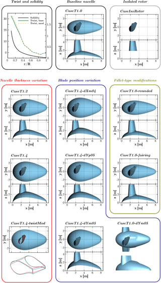
The reference turbine used in this study shall feature the basic geometrical properties of a modern Enercon wind turbine, namely an egg-shaped nacelle and flat-back airfoils with large chord in the inboard region of the rotor. For reasons of confidentiality, no original turbine could be used. Instead, a generic redesign of the Enercon E44 converter is employed. The rotor diameter of this pitch-regulated turbine is 44 m, and the tilt and cone angles are set to zero. The induction, as well as the distributions of the airfoil thickness and the solidity, are representative for the root region of industrial counterparts. However, in the generic version the original airfoils have been replaced by open-source DU and NACA airfoils. Further, the flat-back trailing edge segment is a purely generic design. The latter is responsible for a very high solidity of the rotor in the inner sections as shown in the upper left graph of Fig. 1. The baseline nacelle geometry is drop-shaped with L=8.1 m length and a relative thickness of 48 %. The point of maximum thickness is at . The cut position between the rotating hub and the static nacelle is at .
In order to isolate the governing fluid mechanical effects in the blade root region, different geometrical parameter sets will be addressed that are summarized in Fig. 1. The baseline case described above will be referred to as CaseT1.0. The general effects of the nacelle on the blade root flow shall be analyzed in comparison with an isolated rotor simulation (CaseIsoRotor). From that, it shall be assessed whether the isolated rotor assumption holds for rotors with high solidity.
In a second step, the relative thickness of the nacelle is varied from the baseline, being increased by a factor of 1.2 and 1.4, obtaining the modifications CaseT1.2 and CaseT1.4, respectively. For the latter case, the blade has been redesigned in the root region involving a modified twist distribution (CaseT1.4-twistMod), which is shown in the upper left graph of Fig. 1. The twist angle has been increased in the root region by around 2∘ and approaches the original distribution at .
The next modification category addresses a variation of the blade position relative to the nacelle. These modifications are based on the nacelle with the largest thickness. CaseT1.4-dXm04 denotes a blade shift in the negative x direction by 0.4 m, whereas a movement of the blade in the rotational direction by m will be investigated in the cases CaseT1.4-dYm05 and CaseT1.4-dYp05, respectively. Additionally, the movement of the blade in the direction of rotation shall be applied to the baseline nacelle thickness as well, yielding CaseT1.0-dYm05. The latter also incorporates a hump in the rear part of the suction side of the blade.
Lastly, the geometry in the junction will be modified. In CaseT1.0-rounded, the junction line has been rounded by a constant radius of r=0.4 m, whereas in CaseT1.0-fairing, the radius has been blended from r=0.2 m at the leading edge and on the pressure side to r=0.85 m at the trailing edge of the suction side.
3.1 Flow solver and numerical settings
For the present study, the block-structured finite-volume solver of the compressible Navier–Stokes equations FLOWer (Kroll et al., 2000) by DLR has been used. This code is well suited for simulation of rotary wings, since the fluxes caused by relative grid movements are taken into account. Thereby, the movements of the different components are realized with the overset grid technique (Benek et al., 1986). At the authors' institute, FLOWer is continuously developed to improve simulation capabilities of rotary wings, including high-order schemes (Kowarsch et al., 2013), advanced turbulence modeling (Weihing et al., 2016), fluid structure interaction (Klein et al., 2018; Sayed et al., 2016), wake modeling (Weihing et al., 2017) and optimization for high-performance computing (Letzgus et al., 2018). The code has been extensively validated for wind turbine flows during the MexNext projects, providing accurate predictions of loads and wake measurements (Boorsma et al., 2018; Schepers et al., 2012). During the EU-AVATAR project very competitive results were obtained in the code-to-code comparisons for both uniform and complex inflow conditions (Sørensen et al., 2014, 2017).
In the present study, the discretization of the Euler fluxes is based on central differences with artificial dissipation according to Jameson et al. (1981) using a k4 value of 128. Unless otherwise stated all simulations are performed in steady-state mode. For unsteady simulations, a dual time-stepping discretization according to Jameson (1991) is used. Viscous fluxes are discretized by central differences. Regarding turbulence equations, FLOWer uses a fully implicit discretization and has implemented several one- and two-equation models, as well as Reynolds stress closures. Unless otherwise stated all simulations use the k–ω–SST model by Menter (1994). As discussed in Appendix A this model is able to predict primary vortices in junction flows and showed good agreement with experiments regarding the extent of corner flow separation.
In order to entirely focus on the impact of geometric variations on the aerodynamics of the blade–root region and not to bring in additional model uncertainties due to boundary layer transition, all simulations were conducted fully turbulent. It is pointed out that accurate transition modeling in the considered junction region is nontrivial, since no engineering model exists for the complex transition mechanism within corner flows and even outside of the corner boundary layer, strong cross-flow effects prevail. These are neither taken into account by the basic versions of, for example, the eN envelope method (Drela and Giles, 1987) nor the widely used transport-equation-based local correlation model γ–Reθ of Langtry and Menter (2009). Accounting for cross-flow-induced transition shall be referred to the criteria-based model of Arnal and Juillen (1987) or the recent extensions of the γ–Reθ model by Grabe and Krumbein (2014) and Langtry (2015). Measurements such as those of Zamir (1981) further suggest an earlier transition to turbulence within corner boundary layers compared to corresponding flat-plate conditions. Nevertheless, in order to assess the first-order effects of transition on the results, transitional simulations are conducted for the baseline rotor–nacelle configuration by employing the γ–Reθ model and the envelope method of Drela and Giles (1987). For the latter, the integral boundary layer properties are approximated according to Thwaites (1949). Due to its nonlocal formulation requiring a certain grid topology, this model was only applied to the structure of the blade.
3.2 Grids and boundary conditions
The setup for the simulations considers a periodic 120∘ segment of the flow problem and comprises the meshes for the rotor blade and the nacelle that are embedded into a background grid. For topological reasons, the connections of the blade and the nacelle in CaseT1.0-rounded and CaseT1.0-fairing use independent grids, which were created manually. All other grids were auto-generated by using appropriate Gridgen and Pointwise scripts in order to obtain consistent results for all cases.
The polar background mesh extends 24 rotor radii upstream and downstream and 13 radii in the radial direction in order to minimize effects from too-close far-field conditions. It contains cells in the stream-wise, radial and circumferential direction. The grid spacing near the blade is 0.15 m×0.3 m in the rotor plane.
The mesh of the nacelle covers the whole blade grid and serves as a refinement for the root region of the blade. The boundary layer spacing is adapted from the Reynolds number, ensuring . The geometric stretching factor is 1.1 and comprises 64 extrusion layers. The edge cell size of the latter is equally extended in the radial direction up to to adequately refine the root region. In the circumferential and stream-wise direction 320 and 168 cells are used, respectively.
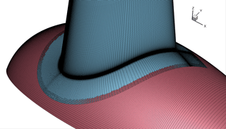
The rotor blade is meshed in a two-stage process. All cases use the same blade mesh for . This part was generated using the Automesh script for rotor blade meshing developed at IAG. The chosen dimensions and spacings were based on the guidelines of the NASA drag prediction workshop (Vassberg et al., 2010). The grid has a C–H topology with an H-block extension of the tip using 288×168 cells in the circumferential and radial direction, 64 cells on the trailing edge and 60 cells in the wake. Again, a Reynolds-number-adapted first cell height was chosen and the near-wall region is resolved with 64 layers, implying a growth rate of 1.11. In the second stage the blade mesh is extended in a conformal way to each individual nacelle, again including 64 cells to refine the boundary layer region of the corner. It was preferred to choose the more expensive H-type refinement of the corner boundary layer in order to avoid skewed cells that would have come when wrapping the blade boundary around the corner. A detailed view of the surface meshes of the blade–nacelle intersection is depicted in Fig. 2 showing the refinement in the junction and the overlapping of the grids.
The configurations CaseT1.0 and CaseT1.4 have also been simulated inviscid by the Euler equations. For those simulations, the grids have been modified by removing all boundary layer refinements, which was necessary to achieve converged solutions.
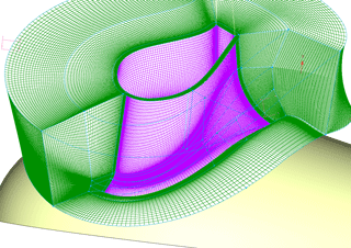
As mentioned before, the rounding of the junction in the cases CaseT1.0-rounded and CaseT1.0-fairing does not allow for the previously described grid topology. A high-quality grid with smooth cell distributions and as little skewness as possible could only be obtained by manually meshing the blade connector. This was conducted in O-type topology and is shown in Fig. 3.
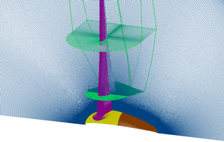
The integration of the blade mesh into the nacelle mesh is illustrated in Fig. 4. In total, a typical setup consists of around 50 M grid points.
Regarding the boundary conditions, the 120∘ domains are mapped periodically and the global domain boundaries carry far-field conditions. All surfaces are treated as no-slip walls (except for the additional Euler simulations of CaseT1.0 and CaseT1.4). However, for the nacelle only the upstream part, the spinner, is rotating (Fig. 4, yellow-colored patches), whereas the rear part (brown colored patches) stays fixed. This is achieved in the rotating grid setup without chimera or sliding mesh interfaces under the exploitation of periodicity by subtracting the boundary velocity from the value of the interior cell before setting the ghost layers.
3.3 Simulation parameters and operating conditions
The main operating point considered is the one for which the power coefficient is maximum, namely at a wind speed of U∞=10 m s−1. In that case the tip speed ratio is λ=6 and the blade pitch angle is zero.Additionally to that point, the configurations CaseT1.0 and CaseT1.0-fairing are analyzed for off-design conditions, as well as by considering the further wind speeds, namely U∞=8, 12 and 15 m s−1.
Unless otherwise stated, all simulations at U∞=8 and 10 m s−1 have been performed in steady-state mode using 150 000 iterations. To verify convergence, selected simulations have been continued unsteadily by five more revolutions using a time step equivalent to 0.25∘ azimuthal movement. The averaged thrust coefficient of the fifth revolution deviated by less than 0.01 % from the averaged value of the last 10 000 iterations of the steady-state solution. Besides the integral values, the fluctuations of the radial force distribution in the root region were very small, since only shallow flow separation prevails. For these reasons and the fact that computational time can be significantly reduced, all results presented in the following are based on steady-state solutions. At the higher wind speeds U∞=12 and 15 m s−1 unsteady simulations were performed. Generally, it is clear that for detailed analyses addressing the unsteady behavior of the separated region, unsteady or even scale-resolving simulation techniques should be applied.
In this main section of the paper the simulation results of the different parameter groups shall be discussed, starting with a comparison of the rotor, including the nacelle with the isolated rotor, and subsequently analyzing specific geometric variations, such as relative nacelle thickness, blade position and junction shape.
4.1 Influence of the grid resolution
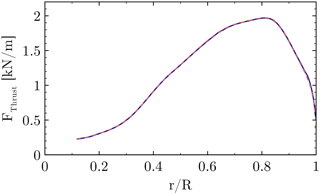
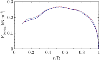
In order to quantify the influence of the grid on the solution, the baseline grid described in Sect. 3.2 shall be compared to a refined version. The blade grid of the refined setup has the same topology as the one described before. It contains 449×97 points in the circumferential and wall-normal direction, 65 points on the trailing edge (the base of the flat back) and a refined wake using 97 points. In the span-wise direction the spacing corresponds to 1 % local chord for the inner half of the rotor. The blade mesh itself contains 73 M cells and the total setup incorporating a Cartesian refinement of the near-blade region consists of 128 M cells. The radial distributions of the sectional thrust and driving forces are cross-plotted for both resolutions in Figs. 5 and 6. The close coincidence of the forces with almost collapsing curves indicates only a small influence of the baseline grid on the solution. The integrated thrust force of the medium mesh is 0.139 % lower compared to the refined grid. For the integrated driving force the deviation is even smaller (0.007 %), although the local deviation of the sectional loading is slightly larger compared to the thrust force. Generally, the trends justify the dimensions and spacings for the grid described in Sect. 3.2. Nevertheless, it will be pointed out in Sect. 4.6 that the effects obtained from the geometric modifications are very local and their global benefits, e.g., obtained by CaseT1.0-fairing at low winds speeds, are at the order of accuracy of the CFD framework used.
4.2 General effects of the voluminous nacelle
To investigate the general effects of the nacelle on the blade root aerodynamics, the cases CaseIsoRotor and CaseT1.0 are compared. The flow field will be characterized, and relevant coherent structures, three-dimensional effects and stall will be addressed. A digression will be made on the challenges of determining the AoA in the root region before the effect of the nacelle on the aerodynamic coefficients is summarized.
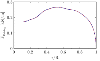
Figure 6Influence of the grid resolution on the sectional driving force. Standard medium mesh (dashed), refined grid (solid).
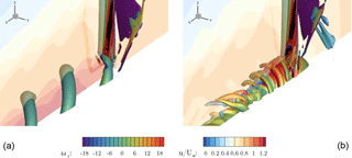
Figure 7Vortices in the root area visualized by a Λ2 iso-surface for CaseIsoRotor (a) and CaseT1.0 (b). The vortices are colored by vorticity in the y direction. The x=0 slice shows the normalized axial velocity component.
4.2.1 Vortical structures
A first impression of the flow field can be gained by visualizing the dominant vortical structures using the Λ2 criterion and the axial velocity distribution in the center cut, as shown in Fig. 7. For CaseIsoRotor the typical root vortices emerge from balancing the bound circulation at the root. The contour color of the iso-surface denotes the vorticity in the y direction and indicates the expected sense of rotation. The normalized axial velocity u∕U∞ in the slice shows a distinct jet through the hub, which is responsible for the relatively high advance rates of the root vortices. Apart from those, no other relevant vortical structures are present that might indicate, e.g., flow separation. Turning to CaseT1.0, shallow flow separation is visible on the suction side near the junction with the nacelle. Moreover, the dominant root vortex seen before has vanished. As will be discussed in more detail in Sect. 4.3, the vortices spiraling around the nacelle evolve from the two vortex legs of the HSV generated in the blade–nacelle junction. As the convecting velocity is significantly smaller than in CaseIsoRotor, these vortices, which are counter-rotating, come very close to each other until eventually mutual interaction occurs. This results in the formation of three-dimensional turbulent structures in the wake of the nacelle. The application of eddy-resolving simulation techniques such as DES could bring further insight into these interaction phenomena (Weihing et al., 2016).
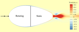
An effect that could be identified to enhance the generation of turbulent structures in the nacelle wake is the consideration of both the rotating spinner and the steady rear part of the nacelle. In previous simulations during the project, in which the entire nacelle had been rotated, these structures were almost absent (Kühn et al., 2018). In order to elaborate the effects of the boundary layer roll-up and detachment in the rear part of the nacelle, isolated simulations of only the spinner and the static rear part of the nacelle have been conducted. The vorticity in the stream-wise direction evaluated in the inertial frame of reference is shown in Fig. 8. The spinner is rotating in positive convention around the x axis and accelerates the surrounding fluid that has no circumferential component far off the wall and therefore generates a negative x vorticity above the spinner. At the interface to the nonrotating part of the nacelle this accelerated layer is suddenly retarded again, inducing a positive x vorticity in the near-wall region above the static surface. This results in a growing shear layer with positive circumferential velocity that eventually detaches from the surface and forms spiraling longitudinal vortices.
Turning to the mid-portion of the wake, a wavy velocity distribution can be observed for both cases at around . It is dedicated to trailed vorticity associated with the span-wise gradients of bound circulation. However, its strength appears to be significantly lower compared to the vorticity directly at the root.
4.2.2 Three-dimensional flow and separation in the root region
The extent of the flow separation and three-dimensional flow patterns can be retrieved from the surface streamlines on the suction side of the blade shown in Fig. 9. For CaseIsoRotor there is no flow separation at the root. The slight radial flow component is dictated by the root vortex rolling from the pressure to the suction side. This is also reflected in the velocity contours in a slice x=2 m just cutting the leading edge of the blade. The plotted velocity contours indicate the deviation velocity describing the vertical motion relative to the ideal circular path. Negative values such as for CaseIsoRotor mean that the streamlines stem from further outboard than assumed from kinematics.
By including the nacelle, its displacement effect evokes an effective inclination angle in that plane, which results in a positive deviation component . For the inner 20 % of the rotor it is more than 0.5 m s−1. The negative values at around are subject to the induction of the mid-trailing vortex described in the previous section. At the inboard sections, a clear flow separation evolves from the junction with the nacelle. It spreads in the radial direction and realigns with the chord direction at about . When focusing on the pressure contours, they are mostly parallel for CaseIsoRotor except for the very inboard region that is directly influenced by the root vortex. For CaseT1.0 significant curvature of the isobars is visible in the area covered by the dividing streamline. As part of the separation process it can be observed that the angle of the shear stress vector turns relative to the pressure gradient, indicating a complex interaction of centrifugal, Coriolis and pressure forces as drivers of the three-dimensional flow. Due to the very high solidity of the blade, which varies between at and at , a high impact of three-dimensional effects can be expected.
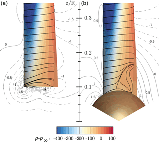
Figure 9Visualization of three-dimensional flow in the root region using streamlines and pressure contours on the suction side of the blade for CaseIsoRotor (a) and CaseT1.0 (b). The contour lines indicate the “deviation velocity” from the ideal kinematic value −Ωy in a slice at x=2 m.
To estimate the share of these forces acting in the y–z plane, the simple balance can be written for a rotation around the x axis as
where the second and third term denote the centrifugal and Coriolis forces, respectively. The velocity components v and w are acting in the chord- and span-wise direction relative to the moving blade rotating with Ω. As can be directly seen in the equation, by definition the Coriolis force vanishes when the velocity is tangential to the rotation, and hence it is expected to be small directly above the nacelle. For the balance in the span-wise direction the Coriolis force changes sign with respect to the chord-wise velocity component, acting inward for attached flow, outward for separated flow and particularly vanishing near the dividing streamline. In contrast to that, the centrifugal force component in the span-wise direction is simply proportional to the z coordinate. Therefore, at the point of separation, the only force to hold the fluid particle on the path of rotation would be a span-wise pressure gradient dp∕dz. The latter can be derived from the radial pressure distribution plotted in Fig. 10 for different chord-wise sections. At , which is close to the separation point, there is virtually no span-wise pressure gradient. Hence, the fluid moves outward solely due to the centrifugal force. It would accelerate towards the tip due to the increasing centrifugal force with z if there was no Coriolis force. As the outward movement is naturally connected with a positive w component it deflects the flow in the chord-wise direction and once there is a chord-wise component and a positive v velocity, an additional inward deflection is induced until eventually the flow realigns with the chord direction. The transport of separated fluid in the outward direction is known as centrifugal pumping (Lindenburg, 2003) and also allows for a pressure recovery in the radial direction, whereby the adverse pressure gradient is smaller compared to the chord-wise direction (see, e.g., in Fig. 10). For equivalent two-dimensional conditions, most of the pressure recovery would therefore occur in the turbulent mixing of the airfoil wake. This explains the commonly observed stall delay of a rotating blade compared to equivalent two-dimensional conditions (e.g., Lindenburg, 2003; Snel et al., 1993).
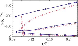
Figure 10The effect of the nacelle on radial pressure distribution on the suction side at (squares), (triangles) and (circles) for CaseIsoRotor (dashed), CaseT1.0 (solid)
The current investigation supports the studies of Du and Selig (2000), Lindenburg (2003) and recently Herráez et al. (2016), who explained radial flow with centrifugal force as well. In this study, the significantly higher blade solidity caused by the flat-back airfoils with large chord is seen to be responsible for a significant impact of three-dimensional effects.
Turning to the front part of the blade, it can be shown that following Bernoulli's principle, the static pressure decreases in the radial direction due to the increasing dynamic pressure of the inflow. This results in an outward pressure gradient. However, it is not believed to be the only reason for the slight radial component of the streamlines near the leading edge, since the pressure gradient is balanced by the Coriolis force in the negative z direction and a strong acceleration in the chord-wise direction prevails, which is in accordance with Schreck and Robinson (2002). As described in more detail in Sect. 4.4 it is more related to an effective sweep angle of the blade relative to the inflow direction. This is again an effect of the high solidity of the blade, which results in a leading edge shift relative to the rotational axis in the y direction. Comparing the pressure levels, the suction peak is significantly reduced in CaseIsoRotor due the induction of the root vortex over the whole inner portion of the rotor.
4.2.3 Determination of the angle of attack in the root region
In order to assess the aerodynamic performance of the individual blade sections in terms of aerodynamic coefficients and to utilize that information in two-dimensional approaches such as BEM or for airfoil design tools, it is essential to accurately determine the angle of attack (AoA) from the three-dimensional flow field. However, it is clear that its extraction is far from trivial as wind velocity and rotation are superimposed by the induction of the wake and the bound circulation of the blade itself. Most approaches such as those compared by Rahimi et al. (2018) aim to eliminate the effect of bound circulation. They provide very similar results at the mid-board blade sections. However, at the blade tip and root, major differences were observed. For the root region they were explained by the massive flow separation in the wake of the very thick airfoils. As for the present rotor, flow separation is only shallow or even absent, differences between the AoA extraction methods are strongly linked to the effects of the root vortex system instead of the dominant vortex shedding caused by massive flow separation. Therefore, two AoA evaluation methods shall be compared with a focus on the root region.
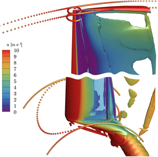
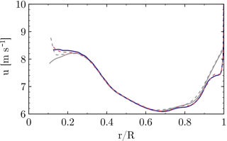
Figure 11Extraction of axial velocity in the inertial frame near the tip and the root using the reduced axial velocity method (Johansen and Sørensen, 2004) (circular arcs) and the line average (closed curves) (Jost et al., 2018) method.
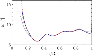
Figure 12Radial distribution of the angle of attack for CaseIsoRotor (dashed) and CaseT1.0 (solid) using the RAV method (gray) and the line average method (colored).
The first is the reduced axial velocity (RAV) method of Johansen and Sørensen (2004), which eliminates bound circulation by azimuthally averaging the axial velocity for each radial section. Secondly, the line average method of Jost et al. (2018) is applied, which averages the velocity vector along closed lines around the blade. Both methods are sketched in Fig. 11. As seen in the figure, for the line average method, the extraction of the velocities occurs along circles that are curved about the rotational axis with a radius corresponding to the location of the quarter-chord point in each section, being centered around the latter. The radius of the projected circle is one chord length. By averaging the planar velocity vector along these curves, Jost et al. (2018) could show that the effect of bound circulation can be eliminated, resulting in pure inflow conditions for that section. The evaluation of the AoA in Fig. 12 shows a lower AoA near the tip for the line average method, since it locally accounts for the induction of the tip vortex, which is smeared out by the azimuthal averaging in the RAV method (Fig. 11). Accounting for the local induction is a desired feature of the line average method and has been shown to accurately reconstruct inflow conditions for corresponding two-dimensional analyses of the near-tip region (Jost et al., 2018; Rahimi et al., 2018). Near the blade root, the AoA predicted by the line average method is higher than obtained by the RAV method. The reason for this is that the azimuthal arc length for averaging the axial velocity in the RAV method is now smaller compared to averaging over the circular line of the line average method (Fig. 11). Particularly, the acceleration of the curving streamlines upstream of the airfoil is not considered in the RAV method. This effect becomes particularly important for CaseT1.0, for which both the blade and the nacelle displace the flow and therefore accelerate it upstream of the leading edge, which is the reason why the increase in AoA is more pronounced for the case including the nacelle. Additionally, it must be noted that for the RAV method the root vortex is occupying about 40 % of the downstream arc length, being more concentrated for the line average method. As a consequence the latter predicts a higher axial velocity in the rotor plane compared to the RAV method (Fig. 13) and therefore a higher AoA. In the remainder of the paper, the AoA will be evaluated with the line average method.
4.2.4 The effect of the nacelle on aerodynamic coefficients
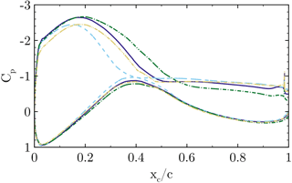
The pressure coefficient Cp is compared for the configurations CaseIsoRotor and CaseT1.0 as well as two-dimensional airfoil simulations in a slice at (Fig. 14). Following Bernoulli's principle, the pressure coefficient has been normalized using the maximum dynamic pressure that can be exploited from the kinematics . In accordance with the independence principle of swept-wing theory, only the component normal to the leading edge is relevant for the aerodynamic properties. Therefore, the z coordinate has been used as the radius for the circumferential component in the dynamic pressure. It should be noted that one could also account for the induction and sweep angle effects, but then the reference state becomes rather ambiguous and difficult to compare among the different cases. Hence, it will be accepted that with the kinematic normalization, Cp might differ from a value of 1 in the stagnation point and it will be attempted to explain this with dominant physical effects.
As already discussed in the previous section, the induction of the root vortex significantly diminishes the suction peak for CaseIsoRotor. For the rotor including the nacelle, the pressure level is lower for the entire suction side of the blade, particularly in the front part of the airfoil. Hence higher lift and lower pressure drag can be expected for CaseT1.0. At the pressure side the differences are small. Only directly at the stagnation point is a higher pressure coefficient obtained by CaseIsoRotor, which is slightly >1. This can be explained by the negative contours (Fig. 9), which indicate that the fluid hitting the airfoil is actually stemming from further outboard compared to its ideal kinematic path. Therefore, fluid of higher momentum is transported towards the leading edge of the airfoil, yielding a higher stagnation pressure than assumed for normalization. By contrast, in CaseT1.0 the stagnation pressure is lower than estimated due to an effective inclination angle that pushes fluid from the inboard sections to the reference cut. Finally, focusing on the aft chord region, it can be confirmed that also for CaseT1.0 the cut is outside of recirculation and that pressure has almost recovered by the centrifugal pumping mechanism.
To further assess the three-dimensionality of the flow in the hub region, a comparison shall be drawn with two-dimensional simulations. These were performed at angles of attack α=10.2, 13 and 14∘, at which the first corresponds to the extracted value from the RAV method for CaseT1.0, the second corresponds to a slightly higher value than obtained from the line average method, which was 12.3∘ for CaseT1.0, and the last is close to the AoA obtained for increased nacelle thicknesses as shown in Sec. 4.3. The 2-D results at reveal no separation. At shallow trailing edge separation is present, which moves forward to at . Compared to the 3-D results, CaseIsoRotor shows a completely different behavior that cannot be mimicked by any 2-D simulation. At first glance the level of the suction peak of CaseT1.0 suggests that would be a good approximation. However, it must be pointed out that when scaling the stagnation pressure in the 3-D results to a value of 1, the distribution increases a bit. Moreover, the visual inspection of corresponding streamline plots compared in that section (not shown here) clearly suggested a larger AoA than 10∘. The distribution in the adverse pressure regime is very similar to the 2-D results at , implying a similar boundary layer stress. The differences on the pressure side are also marked, showing distinctly stronger suction peaks predicted by the two-dimensional simulations. These examinations emphasize the strong three-dimensionality of the flow in the root region of the present rotor and point out that the application of two-dimensional polars in BEM without correction models must be treated with caution, even if there is no massive flow separation.
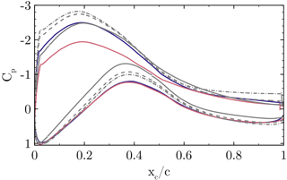
Figure 14Pressure coefficient Cp at for CaseIsoRotor (solid red) and CaseT1.0 (solid blue) compared with two-dimensional simulations (gray lines): (solid), (dashed), (dashed dot).

Figure 15Distribution of aerodynamic coefficients along the blade radius for CaseIsoRotor (dashed) and CaseT1.0 (solid).
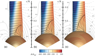
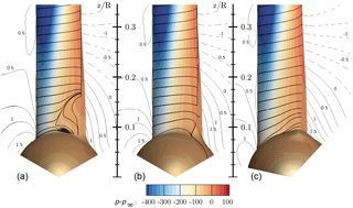
Figure 16Visualization of three-dimensional flow in the root region using streamlines and pressure contours for CaseT1.0 (a), CaseT1.2 (b) and CaseT1.4 (c). The contour lines are plotted for a slice at x=2 m and indicate the velocity , which denotes the deviation from the ideal kinematic path.
The radial distribution of the circulation Γ plotted in Fig. 15a and the lift coefficient (Fig. 15b) confirm the improvement of the aerodynamics in the root region by including the nacelle, which effectively diminishes the harmful inductive effect of the root vortex. This is also reflected in a reduction of the drag coefficient (Fig. 15c) by up to 100 drag counts, although CaseT1.0 involves flow separation. The region of influence of the nacelle extends to . By integrating the driving force within that range, this results in a higher torque of around 20 % for that portion.
4.3 The impact of the relative nacelle thickness
From the previous section it was concluded that an improvement of the aerodynamic properties in the inner portion of the rotor could be obtained by taking into account the nacelle. The attenuation of the root vortex by the nacelle diminished induced drag and increased lift. In this section the effects of the relative nacelle thickness will be analyzed. The thickness has been increased in two steps by a factor of 1.2 and 1.4 for CaseT1.2 and CaseT1.4, respectively.
4.3.1 The effect on flow separation and its driving parameters
The resulting surface streamlines and pressure contours shown in Fig. 16 indicate growing flow separation with increasing nacelle thickness. The extent of the separation measured from the point of maximum thickness of the nacelle to the radial position of reattachment increases from 0.08R over 0.10R to 0.12R for the configurations CaseT1.0, CaseT1.2 and CaseT1.4, respectively. With increasing thickness of the nacelle the separation line moves forward by around 15 %. In addition, it can be noted from the “deviation velocity” that the inclination of the inflow increases with larger relative nacelle thickness.
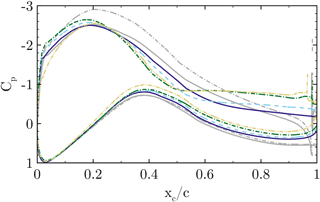
Figure 17Airfoil pressure distribution at for CaseT1.0 (solid), CaseT1.2 (dashed), CaseT1.4 (dashed dot) and CaseT1.4-twistmod (dashed dot dot). The gray curves denote corresponding inviscid simulations.
The comparison of the pressure coefficient in the reference cut at (Fig. 17) confirms the increasing separation for larger nacelle thicknesses. The distinct pressure plateau already suggests a loss of aerodynamic efficiency due to flow separation. The radial pressure gradients in the front part of the blade (Fig. 21) show that greater relative nacelle thickness increases the suction force due to the displacement effect of the nacelle. Also, in the mid-chord and aft chord region the initial pressure level is lower, which increases the radial adverse pressure gradient. Since separation inherently alters the pressure distribution, it is difficult to distinguish between the causes and effects of flow separation. In order to assess whether stronger adverse pressure gradients develop by increasing the nacelle thickness, inviscid reference simulations have been performed for CaseT1.0 and CaseT1.4. The interaction of the inviscid pressure fields is visualized in Fig. 19 using vectors of static pressure acting on the surfaces. For CaseT1.0 the flow accelerates moderately in the junction, reaching the minimum of pressure at about –0.6. It can be shown that the adverse pressure gradient imposed by the nacelle is slightly shifted behind the one from the blade. Turning to CaseT1.4 this is no longer the case, as the suction peaks fairly coincide at around –0.4. Downstream of that point the adverse pressure gradient markedly increases compared to CaseT1.0 and is accordingly devolved on the blade as shown in Fig. 17. In CaseT1.0 the inviscid and viscous suction peaks closely coincide, whereas a significantly higher peak prevails for the inviscid simulation of CaseT1.4. This clearly suggests that the boundary layer of the associated viscous case is increasingly loaded with larger nacelle thickness. From these investigations it can be concluded that a reduction of separation might be achieved by decoupling the interfering pressure gradients of the nacelle and the blade, as is typically done for winglets.
A second aspect that turned out to be crucial for the development of the flow separation is directly linked to the vortex system evolving in the junction of the blade and the nacelle. The motivation for a detailed look into that came by analyzing AoA behavior with respect to the different nacelle geometries (Fig. 22), for which an increasing AoA of around 2∘ could be observed from CaseT1.0 to CaseT1.4. In the beginning of the investigations, it was assumed that the increasing separation was the primary effect of the larger AoA. Therefore, it was attempted to redesign the blade in order to compensate for the AoA, leading to CaseT1.4-twistMod, which employs an increased twist angle in the blade root region of around 2.0∘ (see Fig. 1). Except for the sections very close to the root, the AoA could be effectively reduced. Very inboard, the aerodynamic behavior is obviously strongly nonlinear. Due to the twist modification the flow is redirected, which causes an increase in the axial velocity. The latter is detected by the line average method, which evaluates a lower AoA reduction than expected by the geometric twist modifications. In turn the RAV method was closer to the kinematic value. Nevertheless, when looking at the pressure distribution in Fig. 17, the suction peak is significantly reduced. The evaluation of chord-wise skin friction (Fig. 18) shows that the separation remains almost the same as for CaseT1.4, so it could be concluded that flow separation is not directly affected by an AoA-induced adverse pressure gradient on the blade.
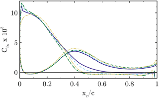
Figure 18Airfoil skin friction distribution at for CaseT1.0 (solid), CaseT1.2 (dashed), CaseT1.4 (dashed dot) and CaseT1.4-twistmod (dashed dot dot).
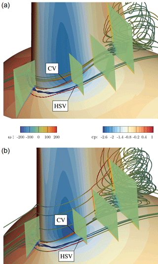
It is seen to depend more on the interacting boundary layers in the junction region of the blade and the nacelle. To shed more light on that, the emerging vortices in the junction are visualized in Fig. 20 for CaseT1.0 and CaseT1.4 using volume streamlines colored by vorticity in the local direction of the velocity vector. Additionally, volume cuts are placed normal to the blade at the leading edge and at . The horseshoe vortex (HSV) is clearly visible and seems to be generated in the stagnation region when the boundary layer of the nacelle approaches the blade. It is rolling inward and its size and strength could be observed to increase with larger nacelle thickness. This behavior is consistent with Simpson (2001), who reports a stronger HSV with increasing AoA. Gand et al. (2015) showed experimentally that the onset of corner separation is delayed by a stronger HSV, since fluid of higher momentum is pushed into the blade boundary layer. This beneficial inductive effect likewise depends on the distance to the blade. By increasing AoA the suction side leg departs from the blade and is further deflected by the Coriolis force.
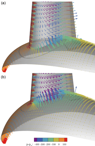
Figure 19Inviscid pressure distribution in the junction region of the blade and nacelle for CaseT1.0 (a) and CaseT1.4 (b).
Directly inboard of the HSV, the counter-rotating corner vortex (CV) evolves from the stagnation point and closely follows the juncture of the blade and the nacelle. Its production depends on the velocity gradients of the interacting boundary layers and its strength was observed to increase for the larger relative nacelle thickness in the adverse pressure gradient region. In contrast to the HSV, the CV remains aligned with the junction. Due to its sense of rotation it seems to be responsible for deforming the near-wall velocity profile on the blade and pulling the boundary layer flow away from the wall. For all cases it was observed that the recirculation area was initiated from the streamline originating in the CV. Thus, high vorticity in the CV might be an important driver for the whole separation process. In particular it should be noted that the configuration with modified blade twist (CaseT1.4-twistMod) revealed quasi-identical values for the CV strength as CaseT1.4 and showed the same amount of separation.
Hence, the second strategy to diminish the detrimental flow separation could be a relief of the mutual loading of the boundary layers of the blade and the nacelle in order to influence the CV strength and propagation. This aspect shall be investigated in Sect. 4.5.
4.3.2 The effect of the relative nacelle thickness on aerodynamic coefficients
To summarize the effects of relative nacelle thickness on the aerodynamic coefficients in the root region, which are plotted in Fig. 22, they confirm the degradation of aerodynamic performance due to stronger flow separation in the inboard region where lift mostly decreases and particularly drag increases. The AoA increases with nacelle thickness, since reduced lift decreases axial induction, which yields higher axial velocities in the rotor plane. The decrease in aerodynamic efficiency is most prominent for the inner 25 % of the rotor radius. It should be noted that there was no measurable benefit for the outer rotor sections as one might have expected due to a displacement effect of the nacelle. In total, the torque generated by one blade decreased for CaseT1.4 by 1.18 % compared to CaseT1.0.
4.4 Movement of the blade position relative to the nacelle
As pointed out in Sect. 4.3.1, a segregation of the interacting pressure gradients of the blade and the nacelle could reduce the overall loading on the corner boundary layer. In order to analyze these effects, the blade was shifted upstream in the axial direction (CaseT1.4-dXm04), as well as upstream and downstream in the circumferential direction (CaseT1.4-dYm05 and CaseT1.4-dYp05, respectively). All modifications were based on the nacelle with the largest of the considered thicknesses, since the strongest effects on the flow separation might be present there and this configuration provides more space for relative blade shifts. The motivation for the first modification was to place the entire blade in front of the point of maximum thickness of the nacelle and therefore locate it in the favorable pressure gradient in the axial direction. The shifting of the blade in the y direction correspondingly aims to investigate the relative location of the pressure gradients in the circumferential direction. Bangga (2018) investigated the lateral shift of rotating profiles for the first time and focused on the exploitation of the y component of the centrifugal force in Eq. (1) to increase rotor performance.
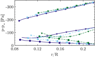
Figure 21The effect of the nacelle thickness on radial pressure distribution on the suction side at (squares), (triangles) and (circles) for CaseIsoRotor (dashed), CaseT1.0 (solid), CaseT1.4 (dashed dot).

Figure 22Aerodynamic coefficients along the blade radius for CaseT1.0 (solid), CaseT1.2 (dashed), CaseT1.4 (dashed dot) and CaseT1.4-twistmod (dashed dot dot).
4.4.1 The effect of the relative blade position on flow separation
Comparing the surface streamlines plotted in Fig. 23 with those of the centered version (Fig. 16), the movement of the blade forward in the axial direction reveals no improvement regarding the extension of the corner separation. Indeed, even a slight deterioration is present, which might be caused by the fact that the inclination angle relative to the blade increases. Turning to CaseT1.4-dYp05, an increase in the separation extent by around 8 % can be observed compared to CaseT1.4. Here, separation already begins close behind 30 % of chord. A significant improvement can be achieved by shifting the blade in the direction of rotation. The separation size in the radial direction is 0.086R, which is only slightly above the baseline CaseT1.0 but already smaller than in CaseT1.2.
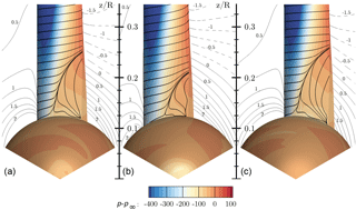
Figure 23Visualization of three-dimensional flow in the root region using streamlines and pressure contours for CaseT1.4-dXm04 (a), CaseT1.4-dYm05 (b) and CaseT1.4-dYp05 (c). The contour lines are plotted for a slice at x=2 m (x=1.5 m for CaseT1.4-dXm04) and indicate the velocity , which denotes the deviation from the ideal kinematic path.
The boundary layer profiles in the reference cut (Fig. 24) give information about the mass flow rate of recirculation. At , CaseT1.4-dYm05 is still attached, whereas slight and moderate backflow is observed in CaseT1.4 and CaseT1.4-dYp05, respectively. Turning to the profiles at , the height of separation massively increases when shifting the blade in the positive y direction. As seen in Fig. 23 this seems to be linked with the volume covered by the downward curvature after the point of maximum thickness of the nacelle and might be “felt” by the blade boundary layer as an additional expansion, which goes along with added adverse pressure loading. This effect is weaker for CaseT1.4-dYm05, for which most of the pressure recovery is achieved forward of that point.
In a similar way, the chord-wise (Fig. 25) pressure distributions are affected in accordance with previous observations. In CaseT1.4-dXm04, the suction peak decreases, but the kink to the pressure plateau remains at the same position as for CaseT1.4. In the aft chord region the pressure recovery has still not initiated as it might be “blocked” by the displacement effect of the ascending nacelle diameter in the vicinity of the blade suction side. In CaseT1.4-dYp05, the massive flow separation yields a collapse of lift at , which results in a reduced suction peak. Both cause a tremendous increase in pressure drag. The latter can certainly be reduced for CaseT1.4-dYm05, for which moderate separation begins at . The downward slope shows that the last part of the pressure recovery already occurs along the airfoil and not predominantly in the wake, as for the other cases.
Regarding the span-wise pressure distribution (Fig. 26), a slight increase in suction force can be noted near the leading edge in CaseT1.4-dYm05 for the whole inner portion, whereas it is markedly lower when moving the blade in the other direction. In contrast to the other cases, CaseT1.4-dYm05 maintains the slope of the leading edge cut, also along . Particularly, CaseT1.4-dYp05 already shows the behavior typically found near the trailing edge, where pressure recovery is redeployed in the radial direction by the centrifugal pumping mechanism. Consistently at , the radial pressure gradient is smallest in CaseT1.4-dYm05, since less recirculating mass needs to be transported outward, which directly yields an earlier realignment of the streamlines in the chord-wise direction as seen in Fig. 23.
From the previous investigations in Sect. 4.3.1 using the Euler simulations, it became clear that a decoupling of the adverse pressure gradients seems necessary to relieve the boundary layer in the junction. As could be shown the axial shifting did not yield any improvement, so it can be deduced that the predominant pressure gradient is the one in the lateral direction. This also seems reasonable as the flow in the junction is aligned with that direction. As the adverse pressure gradient imposed by the nacelle initiates at the outmost point in the circumferential direction, it follows that the entire pressure recovery is additionally loaded in CaseT1.4-dY05. Opposed to that, the segregation of the adverse pressure gradients seems to work for CaseT1.4-dYm05.
Another important aspect to be considered is already attributed to inflow. As shown by the left sketch in Fig. 27, the inner sections of the blade that are shifted forward are affected by inflow stemming from an effectively larger radius that consequently brings in greater momentum. Along the airfoil the flow is pushed downward compared to its ideal kinematic path, which means that it is effectively streaming from a larger to smaller radius. According to the conservation of angular momentum this results in acceleration, which is supportive in overcoming the adverse pressure gradient. When crossing the x–z plane a corresponding retardation would prevail, which additionally reduces angular velocity in CaseT1.4-dYp05. To illustrate this inflow hypothesis, a velocity difference plot between CaseT1.4-dYm05 and CaseT1.4 is presented in Fig. 27 for the reference cut . For this visualization, the solution of CaseT1.4-dYm05 was mapped on top of the centered version. For the entire front part of the airfoil a higher velocity magnitude prevails, which is particularly present inside the boundary layer as seen in Fig. 24. In the stagnation region the inflow velocity is ≈1m s−1 higher for CaseT1.4-dYm05 compared to CaseT1.4. Another distinct peak at which the velocity is markedly higher for CaseT1.4-dYm05 is found in the region of adverse pressure at around . In the rear part of the airfoil the differences originate from the different thickness of the separated wake.
The third effect that is seen to be beneficial for the delay of separation by shifting the blade in the direction of rotation is the sweep angle of the inflow vector with respect to the blade leading edge. At the reference cut it comprises more than 25∘ for CaseT1.4-dYm05, about 17∘ for CaseT1.4 and around 9∘ for CaseT1.4-dYp05. In the radial direction the sweep angle decreases exponentially, but is still greater than 5∘ at the tip for CaseT1.4-dYm05. As the flow turns about the airfoil, the effective sweep angle is not constant along the chord-wise direction, but since most of the lift is generated in the front portion of the blade, it can certainly be stated that sweep effects cannot be neglected. This is supported by the streamlines in CaseT1.4-dYm05 (Fig. 23) that show the typical pattern found for swept wings at high AoA (Obert, 2009), featuring a distinct attachment line instead of a stagnation point, which results in and a prominent span-wise deflection of the streamlines near the trailing edge. In contrast to that, the streamlines remain approximately perpendicular to the leading edge in CaseT1.4-dYp05. The question of whether the principle of independence holds or not is certainly debatable, since rotation introduces span-wise gradients to the flow field. Indeed, for attached boundary layers it is a typical assumption made in BEM codes and is also supported by analyses of Leishman (1989). At high AoA in the stall regime it is generally no longer valid. However, as observed in the boundary layer profiles (Fig. 24), the streamlines (Fig. 23) and pressure distribution (Fig. 25), there is evidence that the sweep angle delays stall and is beneficial for reattachment as it stimulates the outward centrifugal pumping mechanism. An overview of the effect of sweep angle on dynamic stall can be found in the text book of Leishman (2006). Measurements reinforcing the present observations regarding the effect of sweep angle on maximum lift coefficient and stall delay can be found, for example, in Dwyer and Aiccroskey (1971) and in Purser and Spearman (1951).
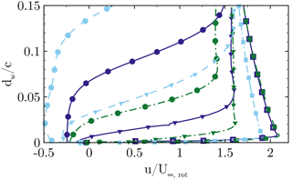
Figure 24Stream-wise normalized velocity in the boundary layer at and (squares; triangles; circles), for CaseT1.4 (solid), CaseT1.4-dYm05 (dashed dot) and CaseT1.4-dYp05 (dashed).
4.4.2 The effect of the blade position relative to the nacelle on aerodynamic coefficients
Regarding the global consequences of the relative blade position, they shall be compared in terms of AoA, lift and drag coefficients plotted for the inner rotor half in Fig. 28. The AoA seems to generally increase when flow separation becomes stronger, which was already seen for the cases in which the nacelle thickness had been increased. Compared to CaseT1.4, the axial movement of the blade decreases torque by 0.96 % as lift declines and drag slightly rises. The significantly stronger flow separation in CaseT1.4dYp05 further deteriorates aerodynamic efficiency and is reflected in a decline of torque by 1.98 %. CaseT1.4dYm05 clearly increases lift and decreases drag in the inner portion of the rotor, which raises torque by 2.1 %. This configuration is already better than CaseT1.2, but still around 1.5 % worse than CaseT1.0. However, as will be shown in the next section, a movement of the blade in the direction of rotation based on CaseT1.0 is able to outperform the aerodynamic behavior of the latter.
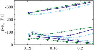
Figure 26The effect of the blade position on radial pressure distribution on the suction side at (squares), (triangles) and (circles) for CaseT1.4 (solid), CaseT1.4-dYp05 (dashed), CaseT1.4-dYm05 (dashed dot).
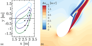
Figure 27Sketch of the shifted profiles at (a). Difference in velocity magnitude between CaseT1.4-dYm05 and CaseT1.4 (b).

Figure 28Aerodynamic properties along the blade radius for CaseT1.4 (solid), CaseT1.4-dXm04 (dashed dot dot), CaseT1.4-dYm05 (dashed dot) and CaseT1.4-dYp05 (dashed).
4.5 Fillet-type modifications in the junction
The second strategy for a potential reduction of corner separation elaborated in Sect. 4.3.1 was the relief of the boundary layer interaction of blade and nacelle, which shall be addressed in this section. The considered configurations modify the geometry of the junction by applying a constant radius of 0.4 m all around the airfoil, denoted CaseT1.0-rounded, and introducing a fairing on the suction side of the blade referred to as CaseT1.0-fairing. These modifications are based on CaseT1.0. Since the movement of the blade in the direction of rotation showed promising results when based on the largest nacelle, this modification shall be transferred to the smallest nacelle (CaseT1.0-dYm05) and included for comparison in the present discussion. In the rear part the junction reveals a plateau, which is from another case not shown here (Kühn et al., 2018), that turned out to be beneficial regarding a restriction of the recirculation area. Since the lateral shift on this nacelle brings along conflicts regarding meshing when moving the blade forward, the periodic segment had to be rotated by 17∘, but due to axisymmetry, this does not change anything regarding periodicity.
4.5.1 The effect on flow separation and the corner vortex system
The streamline plot in Fig. 29 shows that flow separation can be entirely suppressed for CaseT1.0-dYm05 and CaseT1.0-fairing. For the latter quasi-two-dimensional flow conditions prevail with only slight streamline deflection close to the trailing edge, whereas the shifted blade again shows the streamline patterns of swept wings. In CaseT1.0-rounded, flow separation cannot be noticeably reduced compared to CaseT1.0 (Fig. 9).
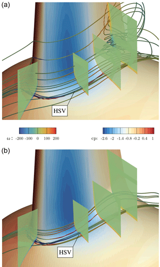
Figure 30Vortex system in the junction of blade and nacelle for CaseT1.0-rounded (a) and CaseT1.0-fairing (b).
More details on the separation mechanism (and suppression) can be gathered from the vortex system shown in Fig. 30. Although the footprint of the surface streamlines indicates a similar separation size for CaseT1.0-rounded compared to the baseline configuration with sharp juncture, recapitulation of Fig. 20 confirms that the separation thickness decreased by introducing the rounding. A side effect of the latter is a weakening of the production of the HSV in the nose region achieved by a homogenization of the shear layer shown in the foremost slice of the approaching nacelle boundary layer interacting with the blade. Although a streamline that is counter-rotating to the HSV vortex rotating can be identified in its vicinity, no harmful corner vortex can build up and manifest itself in the junction. Separation is not initiated from a distinct streamline, but evolves from an isolated vortex generated in the transition from the rounding to the actual blade surface.
These findings were borne in mind in the design of CaseT1.0-fairing. It was decided to reduce the fillet nose radius to 0.2 m in order to increase the strength of the HSV again, which is believed to be helpful for the reduction of corner separation (Devenport et al., 1992). This is certainly the conservative approach, since the separation should optimally be suppressed in combination with a reduced or even eliminated HSV, as the latter increases the interference drag and is a source of noise (Devenport et al., 1992; Simpson, 2001; Zess and Thole, 2001). Towards the trailing edge, the local radius was increased on the suction side to eliminate the unfavorable pressure rise induced by the shape in the transition to the blade previously seen in CaseT1.0-rounded. As can be observed in the streamlines and in the foremost slice plotting the vorticity contours, the strength of the HSV could be increased by a factor of 3. Its suction side leg remains closer to the blade, as it is not displaced by any recirculation and is deformed ovally when traveling downstream.
In the work of Bordji et al. (2015), the formation of the corner vortex correlated well with a peak in the Reynolds shear stress generated by chord-wise and span-wise velocity. In order to assess the development of the corner vortex for CaseT1.0 and CaseT1.0-fairing, the contours of the 〈vw〉 shear stress are depicted in Fig. 31 for a field slice cutting the blade at . The plot confirms the peak and the change in sign of shear stress for CaseT1.0, similarly as observed in Bordji et al. (2015), and gives evidence for the production of the corner vortex. In CaseT1.0-fairing, the large rounding radius ensures a smooth mixing of the boundary layers, resulting in a homogeneous distribution of shear stress that prevents the generation of the CV. Additionally, as was already suggested by the streamline plot in Fig. 29, the formation of the HSV is altered as well. Its strength is lower than in CaseT1.0 and it is stretched. The fact that its center is located significantly closer to the blade surface is beneficial regarding its induction on the blade.
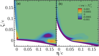
Figure 31Reynolds shear stress 〈vw〉 of the chord-wise and span-wise velocity at . CaseT1.0 (a), CaseT1.0-fairing (b).

Figure 32Pressure coefficient at . CaseT1.0 (solid), CaseT1.0-rounded (dashed), CaseT1.0-fairing (dashed-dot), CaseT1.0-dYm05 (dashed dot dot).
4.5.2 The effect of fillets on the aerodynamic coefficients
Turning finally to the quantities related to aerodynamic efficiency, the pressure distribution in Fig. 32 clearly shows the improvement obtained by eliminating the corner separation for CaseT1.0-dYm05 and CaseT1.0-fairing. The suction force is particularly larger between 40 and 60 % chord, and the boundary layer is able to stand the adverse pressure gradient, which leads to an effectively higher pressure value in the vicinity of the trailing edge.
The attached flow in the corner reduces the AoA (Fig. 33c), consistent with previous observations, being most pronounced for CaseT1.0-dYm05. As already indicated by the pressure distribution in Fig. 32, CaseT1.0-fairing particularly increases lift and only marginally decreases drag, whereas for CaseT1.0-dYm05 the improvements are more related to drag. Overall, tangential force increases in CaseT1.0-fairing due to greater lift. The evaluation of these local improvements on the global blade performance is discussed in the next section.
4.6 Assessment of integral quantities and off-design conditions
As previously mentioned, it is important to put very local aerodynamic improvements in a more global context by analyzing their impact on the sectional thrust and driving loads of the entire blade and by comparing the associated integral forces and moments. It is further important to evaluate the performance in off-design conditions. For this reason the fairing modification, which turned out to be the most promising candidate to eliminate flow separation in the junction of the blade and the nacelle, is investigated in comparison to the baseline geometry for further wind speeds, namely U∞=8, 12 and 15 m s−1. These correspond to the tip speed ratios of 7.48, 5 and 4, respectively. Since the pitch angle is kept constant, the resulting pitch misalignments render somewhat off-design “atmospheric” conditions. The two main questions to be answered are whether the modified fairing geometry wastes performance at lower than the design wind speed and whether an additional benefit can be obtained at high wind speeds at which the overall tendency of flow separation increases. The latter fact can be important with respect to atmospheric turbulence, since gusts may cause local flow separation. If the amount of flow separation can be reduced, an overall reduction of load fluctuations could be achieved.
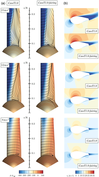
Because unsteadiness is expected to increase with wind speed, the computations at 12 and 15 m s−1 were continued unsteady from a steady-state solution for two more revolutions. Time-averaging of the output data was conducted for the last revolution. An overview on the effects of the wind speed on the flow field can be gained from Fig. 34, in which a comparison is drawn between CaseT1.0-fairing and CaseT1.0 based on the surface distributions of pressure and streamlines, as well as based on the chord-wise velocity in an airfoil section at . At the lowest wind speed U∞=8 m s−1 corner separation has also almost vanished for the baseline geometry and very similar pressure, streamline and velocity distributions are obtained in both cases. For higher wind speeds the AoA increases, yielding a stronger acceleration of the flow in the front part of the airfoil and accordingly in very low surface pressures. As expected, the area of separation increases in the chord-wise and radial direction. After detachment of the flow, the pressure contours flatten out in conjunction with a strong effective de-cambering of the airfoils. This is reflected in a significant recirculation area shown in the velocity contours. Overall, CaseT1.0-fairing significantly reduces the separated area for the high wind speed cases. Particularly, the thickness of the separated wake is markedly reduced and the accelerated regime in the front part of the airfoil is maintained. Both result in a redirection of the airfoil wake, which consequently also turns the aerodynamic force vector.
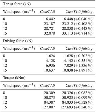
The resulting sectional thrust and driving loads of the blade are shown in Figs. 35 and 36. Their integrated values for the resulting rotor thrust, driving force and torque (for one blade) are summarized in Table 1. It must be pointed out that for the lower wind speeds (U∞=8 and 10 m s−1) an independent integration of each entire curve was not possible, since the effect of the fairing on the overall performance is very small. The latter fact is not surprising when keeping in mind that the flat-back blade offers only little room for improvement compared to the massively separated root sections of conventional blades. The problem is that, particularly for torque, the smallest numerical uncertainties in the prediction of the forces in the outer part of the rotor can outweigh the small improvements obtained in the inner sections. Although the results shown in Figs. 5 and 6 imply a very small influence of the grid on the solution, it must be remembered from Sect. 3.2 that the two cases compared here cannot use exactly the same grids due to topological reasons. Therefore, influences of the grid cannot be eliminated completely. Nevertheless, to examine the influence of the inner portion on the overall performance, each curve was integrated separately only up to . The result was then superposed in both cases by the same value calculated from the baseline configuration for . For the high wind speed cases U∞=12 and 15 m s−1 each curve was independently integrated over the whole radius.
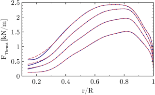
Figure 35Influence of different wind speeds on the sectional thrust force. CaseT1.0 (solid), CaseT1.0-fairing (dashed).
At the lowest wind speed U∞=8 m s−1 the phenomenological impression made before is confirmed in the forces and integral quantities, which are almost identical in both cases. Hence, the first question of whether a performance degradation of the fairing is present at low wind speeds can be negated. For the design wind speed U∞=10 m s−1 the local improvement of the aerodynamics discussed in the previous section is estimated to evoke a very small overall improvement of the extracted power by around 0.1 %. When increasing the wind speed, the relative improvements compared to the baseline configuration become more pronounced. In particular, a rise of the driving force can be observed, which can be related to the relative decrease in the pressure drag caused by the separated airfoil wake. For the largest wind speed this means an overall power gain of 0.54 %.
To summarize these findings it can be stated that it is still important to reduce the stall tendency of wind turbine blades in the inboard sections, even if it might not be a severe problem at the design point of operation, since at higher wind speeds and pitch misalignment flow separation will always expand from the root in the outward direction. Therefore, the smaller the triggering flow separation near the root, the less the mass of separated flow that has to be transported outwards by the centrifugal pumping mechanism, which means that “clean” aerodynamic behavior can be maintained in the outer part of the rotor. With respect to situations of very high atmospheric turbulence levels, in which such temporal pitch misalignments cannot be avoided, an overall performance improvement can be expected in conjunction with a reduction of load fluctuations.
Numerical investigations on the flow in the root region of a wind turbine with flat-back airfoils have been performed using the CFD code FLOWer.
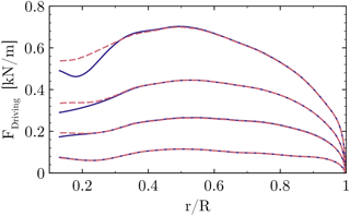
Figure 36Influence of different wind speeds on the sectional driving force. CaseT1.0 (solid), CaseT1.0-fairing (dashed).
The flow in the blade root region has been characterized and the influence of the nacelle on the root flow has been elaborated by comparison with an isolated rotor simulation. Flow separation in the corner of the blade and the nacelle has been identified as one effect that deteriorates the aerodynamic efficiency there. This flow feature is different to the commonly known massive flow separation in the root region of conventional turbines with cylindrical root sections, as it is governed by a vortex system evolving in the junction of the blade and the nacelle. Although the separation is shallow, the very high solidity of the rotor involves strong three-dimensional effects that are determined by centrifugal and Coriolis forces as well as significant sweep angles. It can be stated that when focusing on blade root aerodynamics for those kinds of rotors, a consideration of the nacelle seems to be highly important, as flow topology, aerodynamic coefficients and forces were markedly different when simulating only the isolated rotor.
Following the principal analyses, geometrical properties affecting the blade–nacelle interference have been introduced with the objective of better understanding the underlying flow physics and eventually improve the aerodynamic performance of the rotor in the root region. The first parameter investigated was the relative nacelle thickness. By increasing the nacelle thickness, flow separation in the root region drastically increased, resulting in power losses for the whole rotor of up to 1.18 %. The reasons for the increased flow separation were found from inviscid reference simulations indicating a higher overall adverse pressure gradient for the larger nacelle thickness by means of an unfavorable interaction of the pressure minimums of the blade and the nacelle. An important observation of the viscous simulations was also that increased nacelle thickness intensifies the detrimental interaction of the boundary layers in the junction area. From these findings two threads for diminishing the separation have been elaborated. The first was a decoupling of the pressure gradients of the blade and the nacelle and the second aimed for an alleviation of the harmful boundary layer interaction in the junction region.
A shift of the blade forward in the axial direction did not improve the stall behavior. More effective was the lateral decoupling of the pressure gradients. By moving the blade forward in the lateral direction, stall could be effectively reduced or even eliminated when applying it to the smallest nacelle thickness, and with that, aerodynamic efficiency could be increased. The mechanisms for the improvements were explained by the decoupling of the pressure gradients of the blade and the nacelle and by kinematic reasons that resulted in higher velocities in the front part of the blade and in the region of the adverse pressure gradient. An effective sweep angle further supported the outward transport of separated flow. The shift of the blade in the other direction deteriorated the flow dynamics in the root region compared to the centered base version.
The attachment of fillets in the junction of the blade and the nacelle could be shown to diminish flow separation as well. Particularly effective was the installation of a fairing, implying a small rounding radius at the leading edge and a large radius near the trailing edge of the suction side. With that configuration, separation could be completely eliminated.
The comparison with the baseline geometry showed that for the design wind speed the improved aerodynamic behavior in the inner part of the rotor yields only a small improvement of the overall rotor torque. For off-design conditions it could be shown that a decrease in wind speed yields flow separation that almost disappears for the baseline geometry as well. The fairing modification does not diminish the performance in that case. For higher wind speeds, flow separation becomes generally more severe and the relative improvements obtained by installing the fairing are more pronounced. For the latter, the area of separated wake in the very inboard region of the rotor is significantly reduced, which improves all aerodynamics for the inner one-third of the blade and enhances rotor performance on the order of 0.5%. Hence, as an outlook, an overall performance gain and a decrease in load fluctuations can be expected for turbulent inflow conditions with high levels of turbulence intensity. Investigations on that are dedicated to future work.
Apart from such analyses, it must be stated that this study was meant to demonstrate basic parameters affecting the root flow of a wind turbine with aerodynamically shaped sections down to the hub. Potential for improvement could certainly lie in a detailed parameter optimization of any of the investigated branches. For example, it could be aimed to design fillets that prevent separation and effectively alleviate the horseshoe vortex in order to decrease interference drag.
Since the turbine considered is similar to a commercial machine, data cannot be provided for reasons of confidentiality.
The authors are aware that the prediction of corner flow separation can be rather sensitive to the choice of the turbulence model (Rumsey et al., 2016; Vassberg et al., 2008). For this reason, a priori simulations of the simplified wing–body junction test case of Gand et al. (2015) have been performed. In principle, this is a wing mounted on a flat plate of a certain length operating at an AoA of 12∘. Three hierarchically different turbulence models have been tested: the one-equation SA model (Spalart and Allmaras, 1992), the two-equation k–ω–SST model (Menter, 1994) and the SSG–ω differential Reynolds stress model (Eisfeld, 2004). The results visualizing the corner separation are compared with experimental oil coating in Fig. A1. The SA model, expectedly according to the literature (Bordji et al., 2015; Vassberg et al., 2008), greatly overpredicts the amount of separation, whereas the SSG–ω model predicts hardly any separation. In turn, the SST model provides reasonable results regarding the separation size, with a pattern quite similar to the one obtained by Bordji et al. (2015) using the SA-QCR model (Spalart, 2000). The SST model further showed meaningful results for vortex properties (HSV and CV) and turbulent kinetic energy (Przewlocki, 2017). As the full RSM is computationally more expensive and more delicate concerning robustness, it was decided to stick with the SST model for the considered turbine simulations.
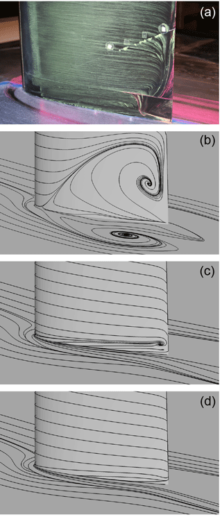
Figure A1Visualization of corner separation for the simplified wing–body junction experiment of Gand et al. (2015) (a). Prediction with SA (b), SST (c) and RSM (d). Figures reproduced from simulations of Przewlocki (2017).
The effect of boundary layer transition on flow separation and turbine loading is elaborated by analyzing the baseline configuration CaseT1.0 with the transitional γ–Reθ–k–ω–SST model and a coupling of the SST model to the eN envelope method (eN–k–ω–SST). The critical N factor is set constant to N=9, and the free-stream turbulence intensity entering the γ equation of the γ–Reθ model is adjusted such that a similar N factor is obtained when applying the relation of Mack (1984). Since laminar separation bubbles are expected, the transitional computations were conducted unsteady and the sectional loads are therefore presented as time-averaged.
The transition location can be identified by the strong local rise of the wall shear stress, which is plotted in Fig. B1 together with the surface streamlines for the fully turbulent and transitional simulations employing the γ–Reθ model. In the front part of the nacelle the lower shear stress suggests laminar flow. At the inner section of the rotor, transition can be identified at . It should be noted that for the thick airfoils considered here, the arc length of laminar flow measured from the stagnation point is considerable. Hence, the “health” of the boundary layer with laminar history is very likely better compared to the one that was assumed turbulent right from the beginning. When the boundary layer becomes subject to the adverse pressure gradient, an earlier separation can therefore be expected for fully turbulent conditions. Accordingly, it can be seen that the extent of the corner separation decreases when taking into account boundary layer transition. However, it can also be noted that the general flow topology does not change.
Turning to the sectional thrust and driving forces cross-plotted in Figs. B2 and B3 for both transitional and fully turbulent computations, at first glance, a good agreement of the γ–Reθ and the eN method is obtained over the whole span. For the thrust load, the difference between transitional and fully turbulent results is most evident in the outer rotor region. In that part, the turbulent boundary layer is very thick and already indicates very small separation near the trailing edge. When the flow has a laminar history no flow separation is visible there. The boundary layer is thinner, which reduces the effective de-cambering of the airfoils so that they can generate more lift and have less drag. The latter increases the driving force. In the inner section of the rotor, the same mechanism holds, which means increasing lift by alleviation of the stress to the boundary layer. Since the twist angles are large, the increasing lift is distinctively reflected in the driving force as well.
It can be concluded that, expectedly, accounting for boundary layer transition increases the thrust and driving forces of the rotor by increasing lift and reducing viscous drag. The span-wise and chord-wise extent of the corner separation is reduced, but no fundamental change in the topology is visible. As suggested by measurements such as those of Zamir (1981), transition in the corner region is typically earlier than for an equivalent flat plate boundary layer. Hence in reality, where pollution and surface roughness also play a role, the extent of separation might lie between that predicted by the fully turbulent and the transitional simulation. Both facts justify the fully turbulent approach when comparing the different geometry modifications.
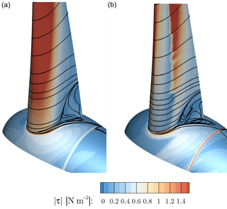
Figure B1Surface streamlines and contours of shear stress magnitude for fully turbulent k–ω–SST simulation (a) and γ–Reθ–k–ω–SST simulation (b).
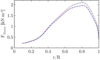
Figure B2Influence of boundary layer transition on the sectional thrust force. Fully turbulent k–ω–SST (dashed), γ–Reθ–k–ω–SST (solid), eN–k–ω–SST (dashed dot).
| Symbol | Unit | Description |
| c | (m) | Airfoil chord length |
| Cd | – | Drag coefficient |
| Cf,x | – | Chord-wise skin friction coefficient |
| Cl | – | Lift coefficient |
| Cp | – | Pressure coefficient |
| dw | (m) | Wall distance |
| L | (m) | Length of the nacelle |
| N | – | Critical amplification factor of Tollmien–Schlichting waves |
| p | (Pa) | Local static pressure |
| p∞ | (Pa) | Ambient pressure |
| q∞,rot | (Pa) | Kinematic stagnation pressure in the rotating frame |
| r | (m) | Local radius |
| R | (m) | Radius of the blade |
| u | (m s−1) | Axial velocity |
| uc | (m s−1) | Velocity in the chord-wise direction |
| umag | (m s−1) | Velocity magnitude |
| U∞ | (m s−1) | Wind speed |
| U∞,rot | (m s−1) | Kinematic inflow velocity in the rotating frame |
| v | (m s−1) | Lateral velocity in the rotating frame |
| w | (m s−1) | Vertical velocity in the rotating frame |
| 〈vw〉 | (m2 s2) | Reynolds shear stress |
| (m s−1) | Vertical motion relative to the ideal circular path | |
| x | (m) | Axial coordinate |
| y | (m) | Lateral coordinate in the rotating frame |
| – | Nondimensional wall distance wall adjacent cell | |
| z | (m) | Vertical coordinate in the rotating frame |
| xc | (m) | Coordinate in the chord-wise direction |
| α | – | Angle of attack |
| Γ | (m2 s−1) | Bound circulation |
| η | (m) | Blade-normal coordinate in the corner frame |
| ρ | (kg m−3) | Density |
| Ω | (s−1) | Rotational speed |
| ω | (s−1) | Vorticity |
| ζ | (m) | Vertical coordinate in the corner frame |
The authors declare that they have no conflict of interest.
The authors acknowledge the German Federal Ministry for Economic
Affairs and Energy for funding this study as part of the project “AssiSt”
(grant number 0325719A) and the High Performance Computing Center
Stuttgart for the contribution of the computational
resources.
Edited by: Christian
Masson
Reviewed by: Arezki Smaili and one anonymous referee
Akay, B.: The root flow of horizontal axis wind turbine blades: Experimental analysis and numerical validation, Delft University of Technology, https://doi.org/10.4233/uuid:2a3f9993-d406-42ee-9d64-57da3fbc0d12, 2016. a
Arnal, D. and Juillen, J.: Three-dimensional transition studies at ONERA/CERT, in: 19th AIAA, Fluid Dynamics, Plasma Dynamics, and Lasers Conference, p. 1335, American Institute od Aeronautics and Astronautics, New York, 1987. a
Bak, C., Zahle, F., Bitsche, R., Kim, T., Yde, A., Henriksen, L. C., Natarajan, A., and Hansen, M. H.: Description of the DTU 10 MW Reference Wind Turbine, available at: http://dtu-10mw-rwt.vindenergi.dtu.dk (last access: 10 August 2018), 2017. a
Baldacchino, D., Ferreira, C., Tavernier, D. D., Timmer, W., and van Bussel, G.: Experimental parameter study for passive vortex generators on a 30 % thick airfoil, Wind Energy, 9, 745–765, https://doi.org/10.1002/we.2191, 2018. a
Bangga, G.: Three-Dimensional Flow in the Root Region of Wind Turbine Rotors, Kassel University press GmbH, Kassel, 2018. a
Bangga, G., Lutz, T., Jost, E., and Krämer, E.: Erratum: “CFD studies on rotational augmentation at the inboard sections of a 10 MW wind turbine rotor” [J. Renew. Sustai. Ener., 9, 023304, 2017], J. Renew. Sustain. Ener., 10, 019902, https://doi.org/10.1063/1.5024529, 2018. a
Benek, J. A., Steger, J. L., Dougherty, F. C., and Buning, P. G.: Chimera, A Grid-Embedding Technique, Air Force Systems Command, Arnold Air Force Station, TN, 1986. a
Boorsma, K., Schepers, J., Gomez-Iradi, S., Herraez, I., Lutz, T., Weihing, P., Oggiano, L., Pirrung, G., Madsen, H., Shen, W., Rahimi, H., and Schaffarczyk, P.: Final report of IEA Task 29, Mexnet (Phase 3), IEA, ECN, Petten, the Netherlands, 2018. a
Bordji, M., Gand, F., Deck, S., and Brunet, V.: Investigation of a Nonlinear Reynolds-Averaged Navier–Stokes Closure for Corner Flows, AIAA J., 54, 386–398, https://doi.org/10.2514/1.j054313, 2015. a, b, c, d
Devenport, W. J., Simpson, R. L., Dewitz, M. B., and Agarwal, N. K.: Effects of a leading-edge fillet on the flow past an appendage-body junction, AIAA J., 30, 2177–2183, 1992. a, b
Drela, M. and Giles, M. B.: Viscous-inviscid analysis of transonic and low Reynolds number airfoils, AIAA J., 25, 1347–1355, 1987. a, b
Du, Z. and Selig, M.: The effect of rotation on the boundary layer of a wind turbine blade, Renew. Energ., 20, 167–181, 2000. a
Dwyer, H. and Aiccroskey, W.: Crossflow and unsteady boundary-layer effects on rotating blades, AIAA J., 9, 1498–1505, 1971. a
Eisfeld, B.: Implementation of Reynolds stress models into the DLR-FLOWer code, Deutsches Zentrum für Luft- und Raumfahrt e.V., Institut für Aerodynamik und Strömungstechnik, Braunschweig, 2004. a
Gand, F., Monnier, J.-C., Deluc, J.-M., and Choffat, A.: Experimental study of the corner flow separation on a simplified junction, AIAA J., 53, 2869–2877, https://doi.org/10.2514/1.j053771, 2015. a, b, c, d
Grabe, C. and Krumbein, A.: Extension of the γ-Reθt model for prediction of crossflow transition, in: 52nd Aerospace Sciences Meeting, p. 1269, American Institute of Aeronautics and Astronautics, https://doi.org/10.2514/6.2014-1269, 2014. a
Guntur, S. and Sørensen, N. N.: A study on rotational augmentation using CFD analysis of flow in the inboard region of the MEXICO rotor blades, Wind Energy, 18, 745–756, 2015. a
Herráez, I., Stoevesandt, B., and Peinke, J.: Insight into rotational effects on a wind turbine blade using Navier–Stokes computations, Energies, 7, 6798–6822, 2014. a
Herráez, I., Akay, B., van Bussel, G. J. W., Peinke, J., and Stoevesandt, B.: Detailed analysis of the blade root flow of a horizontal axis wind turbine, Wind Energ. Sci., 1, 89–100, https://doi.org/10.5194/wes-1-89-2016, 2016. a, b
Himmelskamp, H.: Profile investigations on a rotating airscrew, MAP, Völkenrode, 1947. a
Jameson, A.: Time dependent calculations using multigrid, with applications to unsteady flows past airfoils and wings, American Institute of Aeronautics and Astronautics, 1596, 1991. a
Jameson, A., Schmidt, W., and Turkel, E.: Numerical solutions of the Euler equations by finite volume methods using Runge-Kutta time-stepping schemes, American Institute of Aeronautics and Astronautics, 1259, https://doi.org/10.2514/6.1981-1259, 1981. a
Johansen, J. and Sørensen, N. N.: Aerofoil characteristics from 3D CFD rotor computations, Wind Energy, 7, 283–294, 2004. a, b
Johansen, J., Madsen, H. A., Sørensen, N., and Bak, C.: Numerical Investigation of a Wind Turbine Rotor with an aerodynamically redesigned hub-region, in: 2006 European wind energy conference and exhibition, Athens, Greece, WindEurope, Brussels, 2006. a
Jost, E., Klein, L., Leiprand, H., Lutz, T., and Krämer, E.: Extracting the angle of attack on rotor blades from CFD simulations, Wind Energy, https://doi.org/10.1002/we.2196, 2018. a, b, c, d
Klein, L., Gude, J., Wenz, F., Lutz, T., and Krämer, E.: Advanced CFD-MBS coupling to assess low-frequency emissions from wind turbines, Wind Energ. Sci. Discuss., https://doi.org/10.5194/wes-2018-51, in review, 2018. a
Knezevici, D., Sjolander, S., Praisner, T., Allen-Bradley, E., and Grover, E.: Measurements of secondary losses in a turbine cascade with the implementation of nonaxisymmetric endwall contouring, J. Turbomach., 132, 011013, https://doi.org/10.1115/1.3072520, 2010. a
Kowarsch, U., Keßler, M., and Krämer, E.: High order CFD-simulation of the rotor-fuselage interaction, in: 39th European Rotorcraft Forum, Moscow, New York, 2013. a
Kroll, N., Rossow, C.-C., Becker, K., and Thiele, F.: The MEGAFLOW project, Aerosp. Sci. Technol., 4, 223–237, 2000. a
Kühn, T., Altmikus, Daboul, H., Radi, A., Raasch, S., Knigge, C., Böske, L., Schwarz, T., Heister, C., Möller, A., Lutz, T., Weihing, P., Schulz, C., Thiemeier, J., Mockett, C., Fuchs, M., and Thiele, F.: AssiSt-Schlussbericht gemäß NKBF98, Tech. rep., WRD Wobben Research and Development GmbH, 2018. a, b
Langtry, R.: Extending the Gamma-Rethetat Correlation Based Transition Model for Crossflow Effects, in: 45th AIAA Fluid Dynamics Conference, American Institute of Aeronautics and Astronautics, p. 2474, https://doi.org/10.2514/6.2015-2474, 2015. a
Langtry, R. B. and Menter, F. R.: Correlation-based transition modeling for unstructured parallelized computational fluid dynamics codes, AIAA J., 47, 2894–2906, 2009. a
Leishman, G. J.: Principles of helicopter aerodynamics with CD extra, Cambridge University Press, New York, 2006. a
Leishman, J.: Modeling sweep effects on dynamic stall, J. Am. Helicopter Soc., 34, 18–29, 1989. a
Letzgus, J., Dürrwächter, L., Schäferlein, U., Keßler, M., and Krämer, E.: Optimization and HPC-Applications of the Flow Solver FLOWer, in: High Performance Computing in Science and Engineering'17, 305–322, https://doi.org/10.1007/978-3-319-68394-2_18, Springer, Switzerland, 2018. a
Levy, D. W., Laflin, K. R., Tinoco, E. N., Vassberg, J. C., Mani, M., Rider, B., Rumsey, C. L., Wahls, R. A., Morrison, J. H., Brodersen, O. P., Crippa, S., Mavriplis, D. J., and Murayama, M.: Summary of data from the fifth computational fluid dynamics drag prediction workshop, J. Aircraft, 51, 1194–1213, https://doi.org/10.2514/1.c032389, 2014. a
Lindenburg, C.: Investigation into rotor blade aerodynamics, ECN Report, ECN-C-03-025, Petten, the Netherlands, 2003. a, b, c
Loganathan, J. and Gopinath, G.: Advances in Wind Turbine Aerodynamics, available at: https://www.iitk.ac.in/fmfp14/home_files/gopinath_slide.pdf (last access: 10 August 2018), 2018. a
Mack, L. M.: Boundary-layer linear stability theory, Tech. rep., California Inst. of Technology Pasadena Jet Propulsion Lab, 1984. a
Masson, C. and Smaïli, A.: Numerical study of turbulent flow around a wind turbine nacelle, Wind Energy, 9, 281–298, 2006. a
McCormick, D.: Boundary layer separation control with directed synthetic jets, in: 38th Aerospace Sciences Meeting and Exhibit, American Institute of Aeronautics and Astronautics, p. 519, https://doi.org/10.2514/6.2000-519, 2000. a
Menter, F. R.: Two-equation eddy-viscosity turbulence models for engineering applications, AIAA J., 32, 1598–1605, 1994. a, b
Obert, E.: Aerodynamic design of transport aircraft, IOS press, Amsterdam, the Netherlands, 2009. a
Post, M. L. and Corke, T. C.: Separation control on high angle of attack airfoil using plasma actuators, AIAA J., 42, 2177–2184, 2004. a
Przewlocki, J.: Numerische Simulation einer vereinfachten Flügel-Rumpf Konfiguration, Master's thesis, University of Stuttgart, Institute of Aerodynamics and Gas Dynamics, Stuttgart, Germany, 2017. a, b
Purser, P. E. and Spearman, M. L.: Wind-tunnel tests at low speed of swept and yawed wings having various plan forms, Tech. rep., National Aeronautics And Space Administration Hampton VA Langley Research Center, Langley Field, VA, 1951. a
Rahimi, H., Schepers, G., Shen, W. Z., García, N. R., Schneider, M., Micallef, D., Ferreira, C. S., Jost, E., Klein, L., and Herráez, I.: Evaluation of different methods for determining the angle of attack on wind turbine blades with CFD results under axial inflow conditions, arXiv, 125, 866–876, 2018. a, b
Rumsey, C. L., Neuhart, D., and Kegerise, M. A.: The NASA juncture flow experiment: Goals, progress, and preliminary testing, in: 54th AIAA Aerospace Sciences Meeting, p. 1557, 2016. a, b
Sayed, M., Lutz, T., Krämer, E., Shayegan, S., Ghantasala, A., Wüchner, R., and Bletzinger, K.-U.: High fidelity CFD-CSD aeroelastic analysis of slender bladed horizontal-axis wind turbine, J. Phys. Conf. Ser., 753, 042009, IOP Publishing, 2016. a
Schepers, J. and Snel, H.: Model experiments in controlled conditions, ECN report, Petten, the Netherlands, 2007. a
Schepers, J., Boorsma, K., Cho, T., Gomez-Iradi, S., Schaffarczyk, P., Jeromin, A., Lutz, T., Meister, K., Stoevesandt, B., Schreck, S., Micallef, D., Pereira, R., Sant, T., Madsen, A. H., and Sørensen, N. N.: Final report of IEA Task 29, Mexnet (Phase 1): analysis of Mexico wind tunnel measurements, IEA, Petten, the Netherlands, 2012. a
Schreck, S. and Robinson, M.: Rotational augmentation of horizontal axis wind turbine blade aerodynamic response, Wind Energy, 5, 133–150, 2002. a, b
Schreck, S., Fingersh, L., Siegel, K., Singh, M., and Medina, P.: Rotational augmentation on a 2.3-MW rotor blade with thick flatback airfoil cross sections, in: Proceedings of the 51st AIAA Aerospace Sciences Meeting, AIAA, Vol. 915, https://doi.org/10.2514/6.2013-915, 2013. a
Seifert, A., Bachar, T., Koss, D., Shepshelovich, M., and Wygnanskil, I.: Oscillatory blowing: a tool to delay boundary-layer separation, AIAA J., 31, 2052–2060, 1993. a
Simpson, R. L.: Junction flows, Annu. Rev. Fluid Mech., 33, 415–443, 2001. a, b, c
Snel, H., Houwink, R., Bosschers, J., Piers, W., Van Bussel, G., and Bruining, A.: Sectional prediction of 3D effects for stalled flow on rotating blades and comparison with measurements, in: Proc. European Community Wind Energy Conference, HS Stevens and Associates, LÃ1, Vol. 4, Petten, the Netherlands, 1993. a
Sørensen, N., Hansen, M., Garca, N., Florentie, L., and Boorsma, K.: Power curve predictions wp2 deliverable 2.3, Technical Report, Petten, the Netherlands, 2014. a
Sørensen, N., Garca, N., Voutsinas, S., Jost, E., and Lutz, T.: Aerodynamics of Large Rotors WP2 Deliverable 2.6 Effects of complex inflow for the AVATAR reference rotor and NM80 rotors, Technical Report, Petten, the Netherlands, 2017. a
Spalart, P. and Allmaras, S.: A one-equation turbulence model for aerodynamic flows, in: 30th aerospace sciences meeting and exhibit, p. 439, 1992. a, b
Spalart, P. R.: Strategies for turbulence modelling and simulations, Int. J. Heat Fluid Fl., 21, 252–263, 2000. a
Tanner, M.: Reduction of base drag, Prog. Aerosp. Sci., 16, 369–384, 1975. a
Thwaites, B.: Approximate calculation of the laminar boundary layer, Aeronaut. Quart., 1, 245–280, 1949. a
Van Dam, C., Kahn, D. L., and Berg, D. E.: Trailing edge modifications for flatback airfoils, SAND2008-1781, Sandia National Laboratories, Albuquerque, NM, 2008. a
Vassberg, J., Tinoco, E., Mani, M., Rider, B., Zickuhr, T., Levy, D., Brodersen, O., Eisfeld, B., Crippa, S., Wahls, R., Morrison, J. H., Mavriplis, D. J., and Murayama, M.: Summary of the Fourth AIAA CFD Drag Prediction Workshop (2010), AIAA Paper No, Tech. rep., AIAA-2010-4547, https://doi.org/10.2514/1.c032418, 2010. a
Vassberg, J. C., Tinoco, E. N., Mani, M., Brodersen, O. P., Eisfeld, B., Wahls, R. A., Morrison, J. H., Zickuhr, T., Laflin, K. R., and Mavriplis, D. J.: Abridged summary of the third AIAA computational fluid dynamics drag prediction workshop, J. Aircraft, 45, 781–798, 2008. a, b, c, d
Weihing, P., Letzgus, J., Bangga, G., Lutz, T., and Krämer, E.: Hybrid RANS/LES capabilities of the flow solver FLOWer-application to flow around wind turbines, in: The 6th Symposium on Hybrid RANS-LES Methods, Strassbourg, https://doi.org/10.1007/978-3-319-70031-1_31 2016. a, b
Weihing, P., Schulz, C., Lutz, T., and Krämer, E.: Comparison of the Actuator Line Model with Fully Resolved Simulations in Complex Environmental Conditions, J. Phys. Conf. Ser., 854, 012049, IOP Publishing, 2017. a
Zahle, F. and Sørensen, N. N.: Characterization of the unsteady flow in the nacelle region of a modern wind turbine, Wind Energy, 14, 271–283, 2011. a
Zamir, M.: Similarity and stability of the laminar boundary layer in a streamwise corner, P. Roy. Soc. Lond. A, 377, 269–288, 1981. a, b
Zess, G. and Thole, K.: Computational design and experimental evaluation of using a leading edge fillet on a gas turbine vane, in: ASME Turbo Expo 2001: Power for Land, Sea, and Air, V003T01A083, American Society of Mechanical Engineers, https://doi.org/10.1115/2001-gt-0404, 2001. a
- Abstract
- Introduction
- Baseline reference turbine and considered modifications
- Computational details
- Results
- Conclusions
- Data availability
- Appendix A: The effect of the turbulence model on corner separation
- Appendix B: Assessment of the effect of boundary layer transition
- Appendix C: Nomenclature
- Competing interests
- Acknowledgements
- References


