the Creative Commons Attribution 4.0 License.
the Creative Commons Attribution 4.0 License.
 | 13 Nov 2020
Development of a numerical model of a novel leading edge protection component for wind turbine blades
William Finnegan
Priya Dasan Keeryadath
Rónán Ó Coistealbha
Tomas Flanagan
Michael Flanagan
Jamie Goggins
As the world shifts to using renewable sources of energy, wind energy has been established as one of the leading forms of renewable energy. However, as wind turbines get increasingly larger, new challenges within the design, manufacture and operation of the turbine are presented. One such challenge is leading edge erosion on wind turbine blades. With larger wind turbine blades, tip speeds begin to reach over 300 km h−1. As water droplets impact along the leading edge of the blade, rain erosion begins to occur, increasing maintenance costs and reducing the design life of the blade. In response to this, a new leading edge protection component (LEP) for offshore for wind turbine blades is being developed, which is manufactured from thermoplastic polyurethane. In this paper, an advanced finite element analysis (FEA) model of this new leading edge protection component has been developed. Within this study, the FEA model has been validated against experimental trials at demonstrator level, comparing the deflection and strains during testing, and was found to be in good agreement. The model is then applied to a full-scale wind turbine blade and is then modelled with the LEP bonded onto the blade's leading edge and compared to previously performed experimental trials, where the results were found to be well aligned when comparing the deflections of the blade. The methodology used to develop the FEA model can be applied to other wind blade designs in order to incorporate the new leading edge protection component to eliminate the risk of rain erosion and improve the sustainability of wind turbine blade manufacture while increasing the service life of the blade.
- Article
(1582 KB) - Full-text XML
- BibTeX
- EndNote


In recent years, the global issue of climate change has come to the fore, along with the need to move towards a more sustainable way of living. With this move to sustainable living, the use of renewable energy becomes more prominent, where wind energy has established itself as one of the leading sources of renewable energy. By 2020, the global wind energy capacity is expected to almost double to reach a level of 650.8 GW (Conway, 2015). As the wind energy industry grows, increasingly more wind farms are being developed offshore due to favourable social and environmental factors compared to onshore. With this development in the sector, wind turbine blades are now becoming much larger with the increased resource and the need for fewer turbines. Thereby, the average capacity of wind turbines installed in European waters has doubled, from 2 MW in 2000 to 4 MW in 2014, and Siemens Gamesa announced their 10 MW (193 diameter) wind turbine in 2019 (Siemens, 2019).
As the industry moves towards these larger wind turbine blades, a new challenge presents itself – with higher blade tip speeds, erosion along the leading edge due to the impact of rain droplets begins to occur at an accelerated rate. Leading edge rain erosion is one of the leading reasons for continuous maintenance of the surface of wind turbine blade. As wind turbines move offshore, the cost of maintenance increases 10-fold, due primarily to accessibility difficulties. Additionally, rain erosion along the leading edge of the blades reduces a wind turbine's annual energy production by between 2 % and 25 % (Budinski, 2007).
Currently, a number of leading edge protection methods are available, which are applied to wind turbine blades at the end of their manufacture, including tapes, paints and coatings (Chen et al., 2019). In 2013, a comprehensive review, which details these methods along with a number of other techniques for preventing erosion on the leading edge erosion of wind turbine blades, was compiled by Keegan at al. (2013). Additionally, Dashtkar et al. (2019) reviewed the liquid erosion mechanism, water erosion testing procedures and the contributing factors to the erosion of the leading edge of wind turbine blades, including a brief discussion on the use of carbon nanotubes and graphene nano-additives for improving the erosion resistance of the leading edge. Initially, the protective coatings were made from epoxy or polyester, but over time, these rigid coatings were found to be inadequate; more ductile materials, such as polypropylene and polyurethane, were necessary. In recent years, manufacturers have moved towards multi-layered solutions, which can be designed to optimise performance and as a means of assessing the durability of the protection system. In general, leading edge protection methods can be divided into two categories: in-mould and post-mould solutions (Cortés et al., 2017; Keegan et al., 2013). The in-mould solutions are applied directly to the matrix substrate, using painting or spraying. These coating are typically rigid and brittle and have a high modulus, compared to the more flexible coatings, such as polyurethane (Keegan et al., 2013), which are used for the post-mould solutions. The post-mould protective systems are typically multi-layer systems with the inclusion of filler and primer layers between the laminate substrate and surface coating. These methods provide additional protection from erosion during operation but usually require replacement during the service life of the wind turbine blade. However, this replacement becomes more regular in larger wind turbine blades and, thus, increasingly costly with the need for this additional maintenance.
In recent years, finite element analysis (FEA) has come to the fore for the design and development of composite wind turbine blades. El Chazly (2013) developed a software, based on the finite element method, to perform a static and dynamic analysis of wind turbine blades and found that the maximum stresses occurred at the root of the blades for all configurations in the spanwise direction. Commercial software, with additional routines or modules developed as an add-on, has been used to perform an advanced FEA of composite wind turbine blades. Barnes et al. (2015) used a FEA, in Ansys, to demonstrate the use of an improved design method specifically for blades with low wind speed. During the analysis, the strength constraint imposed was the Tsai–Wu failure criterion in order to determine the optimum structural design for the spar caps and webs of two wind turbine blades. Yeh and Wang (2017) used the finite element analysis software Ansys to perform a stress analysis of a 5 MW composite wind turbine blade, where they found that the largest combined load occurred at a 0∘ pitch angle, and the stress and displacement are the greatest when the wind blade is located at 120∘ angular position from its highest vertex. Zhu and Rustamov (2013) performed a structural analysis, using the finite element method, to evaluate a 750 kW wind turbine blade under various load conditions. Zhou and Yu (2016) also used the finite element analysis software Abaqus to explore the performance of a wind turbine blade and perform a modal analysis. Fagan et al. (2017) performed a FEA, using the finite element analysis software Abaqus, which incorporated a design optimisation genetic algorithm, on a 13 m wind turbine blade. The genetic algorithm resulted in five optimal blade designs, showing a reduction in mass up to 24 %. Tarfaoui et al. (2019) used the finite element analysis software Abaqus to localise the susceptible sections of a full-scale 48 m fibreglass composite offshore wind turbine blades under operational conditions.
Therefore, in this paper, a FEA model of a new wind turbine blade component (LEP) attached to the leading edge of a full-scale wind turbine blade has been developed. The LEP has been designed to protect the leading edge of a wind turbine blade from rain erosion, particularly in the offshore environment. The development details for the FEA model are defined, along with a validation study of the model with the experimental structural static testing of a representative leading edge demonstrator. The validated FEA model has then been applied to a full-scale wind turbine blade with the LEP bonded to the leading edge. Additionally, the effect of the LEP on the structural performance of wind turbine blade has been analysed and discussed.
2.1 Aim and objectives
The overall aim of this report is to develop a finite element model of a novel leading edge protection component (LEP) that is bonded to a wind turbine blade. The purpose of the model is to assist engineers when incorporating the LEP in the design of their wind turbine blades. However, in order to achieve the aim of the study, a number of objectives must be achieved:
-
to develop a validated wind turbine blade FEA model
-
to incorporate the LEP into the model
-
to validate the accuracy of the FEA model using experimental trials through structural testing.
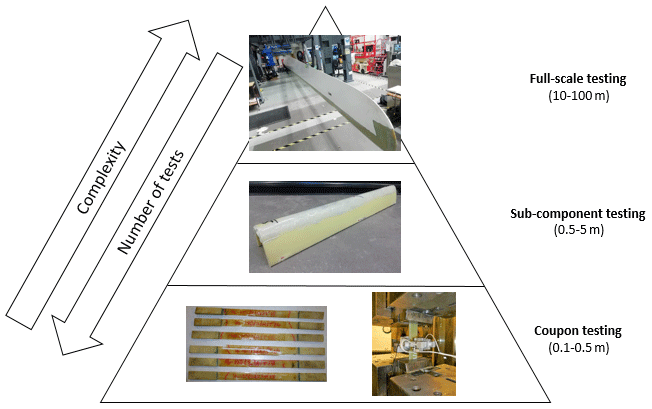
Figure 1Test pyramid methodology for the development of a new wind turbine blade component that is used in this study.
2.2 Methodology
In this paper, a numerical FEA model of a new wind turbine component, LEP, which protects the leading edge of a wind turbine blade, is being developed. Further details on the development of the LEP can be found in Finnegan et al. (2020). The analysis used in this study is based on the proposed test pyramid by Lopes et al. (2016), which is summarised graphically in Fig. 1.
2.3 Governing equations
The FEA model has been developed using Ansys WorkBench 17.1 (Ansys, 2017), where it will combine a number of the Ansys software packages, including DesignModeler and Mechanical (ADPL). The ADPL solver is based on the finite element method, where ADPL incorporates the lay-up details of the composite material substrate that makes up the majority of the wind turbine blade structure.
2.4 Materials
The materials used in the current study are defined in the numerical model using their material properties, which are summarised in Table 1. The composite material used in this study is glass-fibre reinforced powder epoxy, and the material properties for unidirectional (UD), bi-axial (BIAX) and tri-axial (TRIAX) fibre orientations are given in Table 1, along with the lightweight polyurethane (PU) core that is used in the wind blade manufacture. The material properties for the LEP, which is manufactured from a novel thermoplastic polyurethane material, are also given in Table 1.
Table 1Material properties for the thermoplastic and composite materials used in the current study.

a Calculated from testing results to ISO 527, where the tensile modulus is 39 700 MPa and the compressive modulus is 37 900 MPa. b Calculated from testing results to ISO 527, where the tensile modulus is 11 900 MPa and the compressive modulus is 14 000 MPa.

Figure 2Experimental static testing of glass-fibre reinforced specimens, where (a) is the tests being performed and (b) is a comparison of the experimental static testing results with the results from the FEA model.
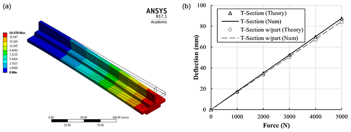
Figure 3Numerical analysis of a cantilever composite T-section with LEP bonded to the underside, showing (a) the deformation (mm) for an end loading of 1000 N and (b) a comparison of the maximum deformation (mm) with the theoretical solution.
3.1 Coupon testing and modelling
3.1.1 Composite test specimen model
The first stage in the model development was the development of a FEA model of a composite test specimen. The use of composite materials within the FEA model presented the greatest challenge and made up the majority of the final model, by mass, as wind turbine blades are made of fibre-reinforced polymer composites. In this study, the composite sections of the wind turbine blade are modelled using shell elements in Ansys DesignModeler, and the plies are modelled using the “layered section” in Ansys Mechanical ADPL. Composite material plies are defined by specifying the ply thickness and orientation. The resulting material properties of the part can then be used within the FEA solver. Young's modulus of the ply (Eply) is estimated using the rule of mixtures (Agarwal et al., 2017), as follows:
where κ is a correction factor that accounts for the fibre area, the fibre diameter distribution, the interface and the fibre orientation distribution; Vf is the fibre volume faction (0.52); Ef is the Young modulus of the fibre (72.4 GPa); Vm is the matrix volume fraction; and Em is Young's modulus of the matrix (3.89 GPa). The FEA when loads are applied within the numerical composite material model is performed using Ansys Mechanical Static Structural with Ansys Workbench.
In order to validate the accuracy of this numerical composite material model, a validation study took place, where the results of the numerical model were compared to the results from physical testing of fibre-reinforced polymer composite specimens. The specimens were manufactured from E-glass bi-axial material (AHLSTROM 62042) that was prepared with a quasi-isotropic lay-up and infused with epoxy resin (Gurit's Ampreg 22) with a slow hardener using the vacuum-assisted resin transfer (VART) method at ÉireComposites Teo. The quasi-isotropic lay-up for 16 ply panels was specified as [, )2]s, and the specimen was cured for 48 h at room temperature (21 ∘C), followed by a postcure at 75 ∘C for 5 h.
The static tensile testing was carried out in accordance with ASTM D3039: Standard Test Method for Tensile Properties of Polymer Matrix Composite Materials (ASTM, 2017) using a 250 kN Zwick test machine with wedge grips, as shown in Fig. 2a. The test composite specimen is loaded at a speed of 2 mm min−1, and the stain is measured between 0.1 % and 0.3 % using a bi-axial extensometer in order to calculate Young's modulus of the specimen. In total five specimens were tested. The results of this physical testing, including an upper and lower bound for the test results and the average based on the mean Young modulus from this physical testing (calculated to be 19 567.2 MPa for the material), are compared to the results from the numerical composite material model, which estimated Young's modulus of the material as 18 926.5 MPa. Therefore, the results are found to be in very good agreement, as shown in Fig. 2b, with the numerical model underestimating by approximately 3 % but very close to the results of one of the specimen physical tests. Therefore, this difference is well within the allowable experimental error expected for this study. Young's modulus obtained here is also in line with that of Kennedy et al. (2018), who reported a value of 19 300 MPa for a similar epoxy-infused E-glass material.
3.1.2 Cantilever composite T-section model
The numerical composite material model developed in Sect. 2.4.1 is expanded to form a composite T-section part. This part has a fixed support on one side and a vertical load applied at the other, as a cantilever set-up. The model is then further advanced by bonding LEP to the underside of the composite T-section, which is representative of the final LEP bonded to a wind turbine blade and is shown in Fig. 3a. Again, there is a cantilever set-up with a vertical lead applied.
The maximum deformations of the composite T-section with and without LEP bonded to the underside are compared in Fig. 3b, under a range of loadings from 1000 to 5000 N. For each of the models, the results of numerical simulations are compared to the theoretically predicted values, where the maximum deflection, ymax, can be calculated using
where F is the vertical load applied at the end of the cantilever, L is the length of the cantilever, E is Young's modulus and I is the moment of inertia of the cross section. As can be seen in Fig. 3b, the difference between the results of the FEA model and the theoretically predicted values for a composite T-section with and without the LEP bonded to the underside is approximately 1 % and 0.2 %, respectively. The influence of the LEP bonded to the underside of the composite T-section increases the stiffness by approximately 3.5 %.
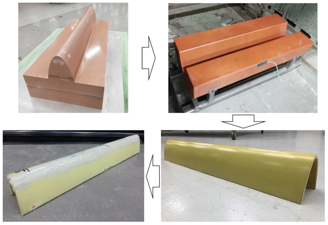
Figure 4Summary of the main manufacturing stages for the demonstrator, from top left clockwise: demonstrator pattern, thermoset mould, powder epoxy glass-fibre reinforced leading edge demonstrator and demonstrator with LEP bonded in place.
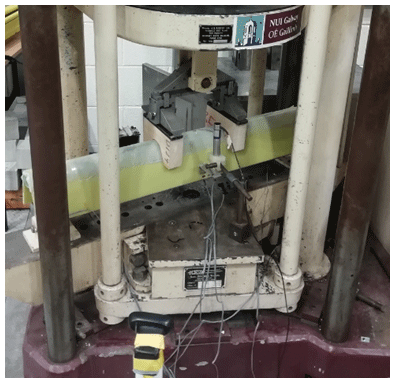
Figure 5The leading edge demonstrator installed for a four-point bending test in the Denison 500 test machine at NUI Galway.
3.2 Leading edge demonstrator model validation
3.2.1 Demonstrator manufacture
In order to perform a validation study of the initial model of the LEP on a wind turbine blade, a leading edge demonstrator was manufactured. A summary of the four main manufacturing stages for the leading edge demonstrator is shown in Fig. 4.
The demonstrator was designed based on the leading edge profile of the cross section at 57 m from the root of a commercial 63 m blade, which is a blade from a 2.6 MW wind turbine that has a rotor diameter of 128 m. The profile is coupled with a rectangular base to form the cross section of the demonstrator pattern. The demonstrator pattern has a continuous cross section and was produced using a five-axis CNC machine from multiple layers of polyurethane, where the final pattern is shown in the top left of Fig. 4. A thermoset mould is then manufactured from this pattern using a glass-fibre reinforced high-temperature epoxy composite material, which is shown in the top right of Fig. 4.
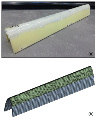
Figure 6Leading edge demonstrator used for the validation study, showing (a) the physical model used for the experimental trials and (b) the meshed geometry used in the numerical FEA model.
The blade substrate, which is made of glass-fibre reinforced powder epoxy composite material, was laid up on the mould. The lay-up is one layer of TRIAX (1.4 mm thick), eight layers of UD (0.9 mm thick) and one layer of TRIAX (1.4 mm thick) that are all orientated at 0∘ along the long edge of the demonstrator, which forms a part with a total thickness of 10 mm. The LEP is then bonded to the blade substrate using an epoxy-based adhesive and cured at 70 ∘C to form the final leading edge demonstrator, which is shown in the bottom left of Fig. 4.
3.2.2 Demonstrator testing
The testing procedure for the leading edge demonstrator was a four-point bending static test using the Denison 500 test machine at NUI Galway, where the test set-up is shown in Fig. 5. The demonstrator was simply supported at a spacing of 900 mm between the two supports, and the static loading was applied vertically downwards in two places at a distance of 230 mm, where each loading point is 115 mm from the centre of the specimen. Initially, a number of trial specimens were tested in a similar set-up to inform the final test campaign.
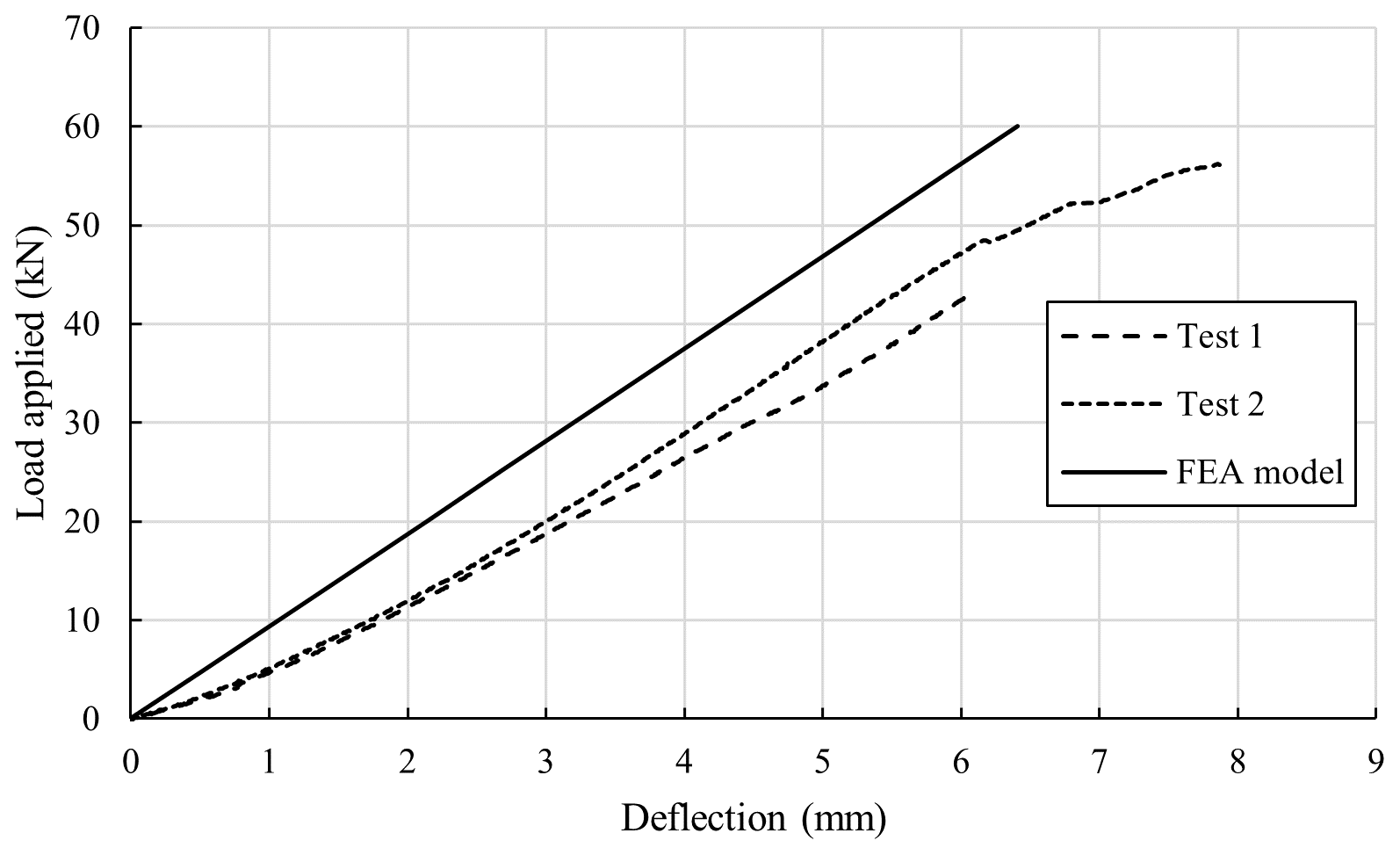
Figure 7Deflection (mm) of the centre of the specimen against load (kN) applied during the testing (data for Test 3 not available).
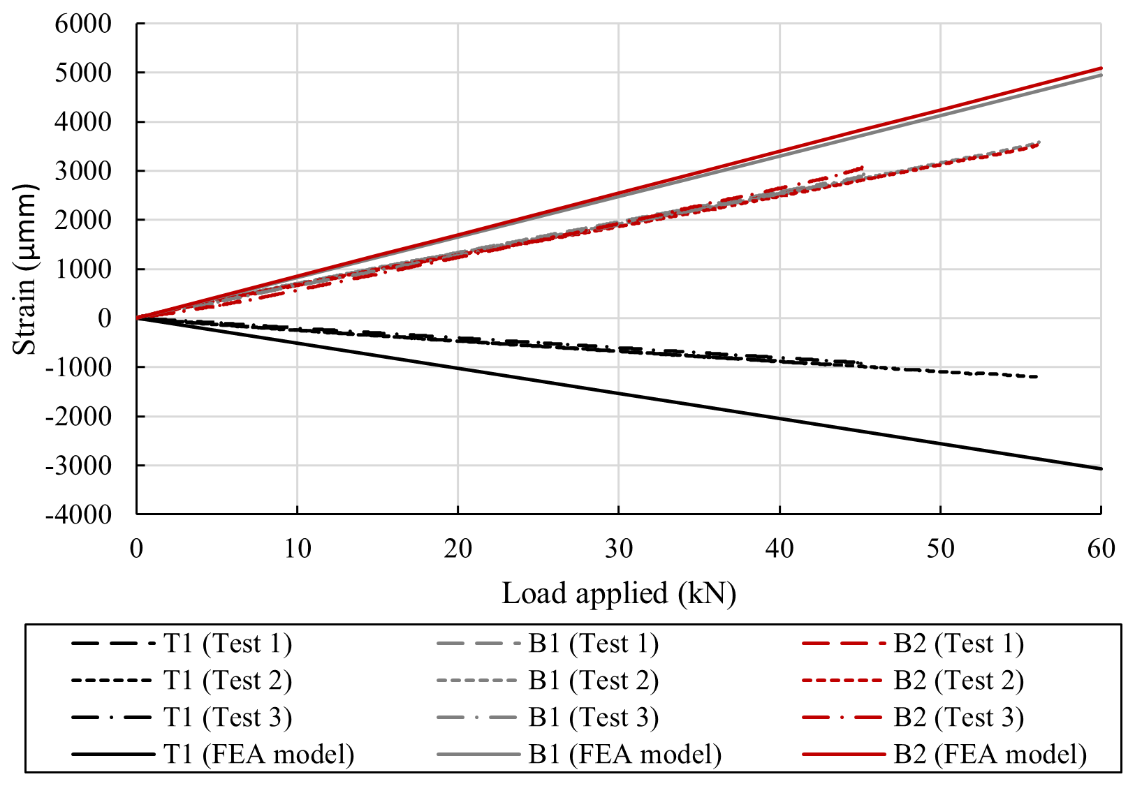
Figure 8Strain recorded by the three linear strain gauges at the centre of the demonstrator during each test.
In order to obtain the required data, the demonstrator was instrumented with three linear electrical resistance strain gauges, which have a strain limit of approximately 5 %, and one LVDT (linear variable differential transformer displacement sensor). The three strain gauges were located at the centre the demonstrator at the locations of highest strain and stresses – one at the top and one on either side of the outside surface at the bottom – and the LVDT at the centre at the location of highest deflection, which can be seen in place in Fig. 5.
Three tests, where the demonstrator was continuously loaded, were performed, and the maximum load applied during the testing was 52.2 kN. Failure in the demonstrator occurred at one of the support locations, where the internal support structure de-bonded from the demonstrator substrate. However, no material failure within the demonstrator substrate was evident during or after the test.

Figure 9Contour plots showing the results from the FEA model when a loading of 40 kN is applied to the demonstrator, where (a) is the deflection and von Mises (equivalent) stress and (b) is the frictional stress between the LEP and the blade substrate.
3.2.3 Demonstrator FEA model analysis
The FEA model developed and validated in Sect. 3.1 is advanced in order to model the leading edge demonstrator, which was manufactured and mechanically tested. The mesh for the computational domain of the blade substrate is defined using shell elements, and the mesh for the computational domain of the LEP is defined using solid elements, where a contact region is defined between the outer blade surface and the inner LEP surface. The adhesive used for the physical demonstrator is also modelled using this contact region, where a “bonded” connection is defined, which restrains movement between the two surfaces in both the normal and tangential direction and, therefore, assumes a “perfect” attachment. The lay-up for the blade substrate is the same as the lay-up specified in Sect. 3.2.1, which is specified at the shell elements using the “layered section” in Ansys Mechanical ADPL, and the material properties specified in the FEA model are those given in Table 1. The mesh for the computation domain has a specified maximum element size of 10 mm, resulting in a mesh containing 15 100 elements with 27 500 nodes. The computational domain for the demonstrator FEA model is shown alongside the leading edge demonstrator in Fig. 6. Displacement restraints have been specified at the two support points to model a simply supported system, and two-point loads have been specified, in order to represent a four-point bending static test, which was performed on the leading edge demonstrator in Sect. 3.2.2.
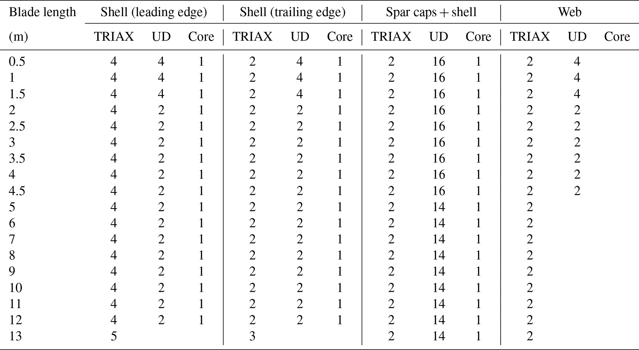
Table 2Details of the composite ply lay-ups for the full-scale wind turbine blade.
3.2.4 Demonstrator FEA model validation
The results of the experimental testing, which is discussed in Sect. 3.2.2, have been compared to the results from the FEA model of the leading edge demonstrator. A comparison between the two sets of results for vertical load applied against the maximum deflection of the demonstrator is shown in Fig. 7. The FEA model underestimates the deflection occurring during the testing but is in reasonable agreement. The strain occurring during the testing was monitored at three locations along the centre of the demonstrator, which can be seen in Fig. 5. The FEA model overestimates the level of strain occurring, but the directionality is constant, which can been in Fig. 8. Overall, there is reasonable agreement between the two sets of results.
The FEA model is then used to examine the frictional stress between the LEP and the blade substrate for a loading of 40 kN. The maximum frictional stress is 6.4 MPa, as shown in Fig. 9b. This occurs at the contact points of the loading mechanism, which would not happen in operation. Contour plots showing the deflection and von Mises (equivalent) stress are also shown in Fig. 9a.
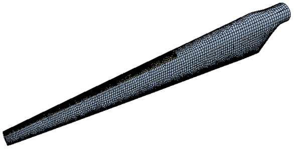
Figure 10Meshed geometry (computational domain) used for the FEA of the full-scale wind turbine blade with LEP bonded to the leading edge (as shown in yellow).
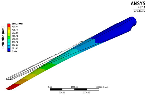
Figure 11Deflection of the FEA model of the full-scale wind turbine blade under the defined loading.

Figure 12Comparison of the deflections from the FEA model of the full-scale wind turbine blade under the defined loading along the length of the blade with and without the LEP bonded and the experimental results (Fagan et al., 2017).
3.3 Full-scale wind turbine blade model
The validated FEA model is then applied to a full-scale (13 m) wind turbine blade with a LEP bonded to the leading edge along the 8 m closest to the tip.
3.3.1 Model details
The full-scale wind turbine blade is a 13 m long blade from a 225 kW wind turbine, which has a total mass of approximately 800 kg. The blade is manufactured from glass-fibre reinforced powder epoxy composite material using a novel “one-shot” manufacturing process, which cures the different parts of a wind turbine blade (i.e. skin sections, spar caps web and root) in one single process to avoid the need for gluing. Steel inserts in the root of the blade provide a connection to the turbine hub, which will be modelled as a “fixed support” at the root within the FEA model. An 8 m long LEP is attached to the leading edge of the blade towards the tip. This is shown in yellow in the meshed geometry in Fig. 10. The LEP is a thermoplastic polyurethane that has been selected due to its high tolerance to rain erosion and UV resistance. The main components of the wind blade (shell, spar, web) were defined using shell elements, where the composite lay-up is defined using the material properties, thickness of each play and the ply orientation, and the LEP is defined using a solid region extruded from the blade surface along the leading edge. Similar to the precious section, the contact region between the LEP and the blade surface is defined as a bonded connection.
The blade is manufactured from three materials – UD, TRIAX and PU core – which are described in detail in Sect. 2.4, and their material properties are given in Table 1. The main structural element of the blade is the spar caps, which are primarily manufactured from UD plies that are orientated along the length of the blade, and shear webs, which are manufactured from both UD and TRIAX plies that are also orientated along the length of the blade. Each of the plies has a thickness of approximately 1 mm. The composite ply lay-up details for the wind turbine blade are listed in Table 2.
A maximum element size was specified of 200 mm when creating the mesh for the computation domain, which is shown in Fig. 10. This resulted in a mesh containing 52 500 elements with 90 600 nodes.
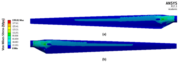
Figure 13Contour plots showing the von Mises (equivalent) stress from the FEA model of the full-scale wind turbine blade under the defined loading.
3.3.2 FEA model analysis
In order to ensure the accuracy of the FEA model and the wind turbine blade set-up, the results (blade deflection) from the FEA model are compared to the experimental trials performed by Fagan et al. (2017) for the same blade. The loading used in the experimental trials was defined from the maximum expected wind loading on the blade in operation, and this same loading is used within the analysis presented in this study. In this study, the loading was applied as three-point loads along the blade, which were specified as 7.32 kN at 5 m from the blade root, 3.38 kN at 10 m from the blade root and 2.3 kN at 12 m from the blade root (1 m from the tip of the blade).
The deflection of the blade that is predicted in the FEA model (seen in Fig. 11) agrees well with the results from the experimental trials performed in Fagan et al. (2017), which can be seen in Fig. 12. The mechanical performance of the LEP component during operation is not expected to contribute to the mechanical performance of the wind blade. However, based on the comparative results in Fig. 12 for the wind blade with and without the LEP attached, the addition of the LEP increases the stiffness of the blade. Nevertheless, it is essential that the von Mises stresses on the component are lower than the allowable stress of the materials used for the LEP component.
The von Mises (equivalent) stress on the blade is shown in Fig. 13 for when the defined loading is the same as in the experimental trials performed in Fagan et al. (2017). The highest stresses are along the spar caps at 1.3 m from the root of the blade of up to 200 MPa. This value is well below the maximum allowable stress for the blade substrate of 643 MPa, which is the compressive strength of UD glass-fibre reinforced powder epoxy mechanically tested at an orientation of 0∘. The tensile strength of UD glass-fibre reinforced powder epoxy when mechanically tested at an orientation of 0∘ was found to be 782 MPa. The von Mises stress imposed within the LEP material is 2.6 MPa throughout the component except for a concentrated high stress area near the tip of the blade, where the stresses are above the yield strength of the material (6 MPa). The frictional stress along the bonded contact between the blade substrate and the LEP component was found to be 32.8 MPa except for a concentrated high stress area, again, near the tip of the blade, where the frictional stress reaches 82 MPa. This is higher than the maximum tensile stress of the epoxy adhesive of 49 MPa. This high stress area near the tip will need to be addressed in the component design and manufacture stages of development.
An advanced FEA model of a new leading edge protection component (LEP) for wind turbine blades has been developed in this study. The FEA model has been validated against experimental trials at demonstrator level, comparing the deflection and strains during testing, and was found to be in good agreement. A full-scale wind turbine blade is then modelled with the LEP bonded onto the blade's leading edge and compared to previously performed experimental trials (Fagan et al., 2017), where the results were found to be well aligned when comparing the deflections of the blade.
The methodology used to develop the FEA model can be applied to other wind blade designs in order to incorporate the new LEP as a protection from rain erosion along the leading edge of the blade. The results of the model will allow engineers to explore the effect of the new LEP on their existing wind blades, including the blade stiffness, von Mises stress on the blade and frictional stress at the bond. Additionally, there is scope to extend the study to develop and explore other protection systems and investigate the effect of stress distribution, stiffness adhesive and viscoelastic properties on the system.
The structural integrity of wind blades in the offshore environmental is paramount to the success of the sector. Regular maintenance will prove much more difficult and costly offshore compared to onshore wind installations. A robust leading edge protection system that protects the blade from rain erosion for the duration of its life span will significantly reduce the need for maintenance and, in turn, increase the reliability and service life of the blades.
Publicly available testing data are provided in this publication. Additional testing data may be granted through contact with William Finnegan.
WF provided conceptualisation, data curation, investigation, methodology, formal analysis and led the writing for the paper. PDK and RÓC provided data curation and research investigation. TF provided supervision, along with JG, conceptualisation and funding acquisition for the research. MF provided conceptualisation and project administration to facilitate the writing of this paper.
The authors declare that they have no conflict of interest.
This article is part of the special issue “Wind Energy Science Conference 2019”. It is a result of the Wind Energy Science Conference 2019, Cork, Ireland, 17–20 June 2019.
This research has been supported by the Executive Agency for Small and Medium-sized Enterprises (EASME), the European Commission (grant no. EASME/EMFF/2017/1.2.1.12/S1/06/SI2.789307), the Sustainable Authority of Ireland (SEAI) (grant no. 19/RDD/430), and the Science Foundation Ireland (SFI) (grant no. 12/RC/2302_2).
This paper was edited by Lars Pilgaard Mikkelsen and reviewed by two anonymous referees.
Agarwal, B. D., Broutman, L. J., and Chandrashekhara, K.: Analysis and performance of fiber composites, John Wiley & Sons, Hoboken, New Jersey, USA, 2017.
Ampreg 22: Epoxy Laminating System Datasheet, available at: http://www.gurit.com/-/media/Gurit/Datasheets/ampreg-22.ashx, last access: 20 April 2018.
Ansys: Ansys®CFX (Release 17.1): CFX-Solver Theory Guide, Ansys Inc., Canonsburg, Pennsylvania, USA, 2017.
ASTM: D3039 / D3039M-17: Standard test method for tensile properties of polymer matrix composite materials, ASTM International, West Conshohocken, USA, 2017.
Barnes, R. H., Morozov, E. V., and Shankar, K.: Improved methodology for design of low wind speed specific wind turbine blades, Compos. Struct., 119, 677–684, https://doi.org/10.1016/j.compstruct.2014.09.034, 2015.
Budinski, K. G.: Guide to friction, wear and erosion testing, ASTM international, West Conshohocken, USA, 2007.
Chen, J., Wang, J., and Ni, A.: A review on rain erosion protection of wind turbine blades, J. Coat. Technol. Res., 16, 15–24, https://doi.org/10.1007/s11998-018-0134-8, 2019.
Conway, J.: World wind power to almost double to 650GW by 2020, in: The Australian, News Corp Australia, New South Wales, Australia, 2015.
Cortés, E., Sánchez, F., O'Carroll, A., Madramany, B., Hardiman, M., and Young, T. M.: On the material characterisation of wind turbine blade coatings: the effect of interphase coating–laminate adhesion on rain erosion performance, Materials, 10, 1146, https://doi.org/10.3390/ma10101146, 2017.
Dashtkar, A., Hadavinia, H., Sahinkaya, M. N., Williams, N. A., Vahid, S., Ismail, F., and Turner, M.: Rain erosion-resistant coatings for wind turbine blades: A review, Polymers and Polymer Composites, 27, 443–475, https://doi.org/10.1177/0967391119848232, 2019.
El Chazly, N. M.: Static and dynamic analysis of wind turbine blades using the finite element method, Renew. Energ., 3, 705–724, https://doi.org/10.1016/0960-1481(93)90078-U, 1993.
Fagan, E. M., Flanagan, M., Leen, S. B., Flanagan, T., Doyle, A., and Goggins, J.: Physical experimental static testing and structural design optimisation for a composite wind turbine blade, Compos. Struct., 164, 90–103, https://doi.org/10.1016/j.compstruct.2016.12.037, 2017.
Finnegan, W., Flanagan, T., and Goggins, J.: Development of a Novel Solution for Leading Edge Erosion on Offshore Wind Turbine Blades, in: Proceedings of the 13th International Conference on Damage Assessment of Structures, Porto, Portugal, 9–10 July 2019, 517–528, 2020.
Keegan, M. H., Nash, D. H., and Stack, M. M.: On erosion issues associated with the leading edge of wind turbine blades, J. Phys. D Appl. Phys., 46, 383001, https://doi.org/10.1088/0022-3727/46/38/383001, 2013.
Kennedy, C. R., Jaksic, V., Leen, S. B., and Brádaigh, C. M. Ó.: Fatigue life of pitch- and stall-regulated composite tidal turbine blades, Renew. Energ., 121, 688–699, https://doi.org/10.1016/j.renene.2018.01.085, 2018.
Lopes, C. S., González, C., Falcó, O., Naya, F., Llorca, J., and Tijs, B.: Multiscale virtual testing: the roadmap to efficient design of composites for damage resistance and tolerance, CEAS Aeronaut. J., 7, 607–619, https://doi.org/10.1007/s13272-016-0210-7, 2016.
Siemens Gamesa launches 10 MW offshore wind turbine; annual energy production (AEP) increase of 30 % vs. predecessor, available at: https://www.siemensgamesa.com/newsroom/2019/01/new-siemens-gamesa-10-mw-offshore-wind-turbine-sg-10-0-1 93-dd, last access: 1 March 2019.
Tarfaoui, M., Nachtane, M., and Boudounit, H.: Finite Element Analysis of Composite Offshore Wind Turbine Blades Under Operating Conditions, J. Therm. Sci. Eng. Appl., 12, 011001, https://doi.org/10.1115/1.4042123, 2019.
Yeh, M.-K. and Wang, C.-H.: Stress analysis of composite wind turbine blade by finite element method, IOP Conference Series: Materials Science and Engineering, 012015, 27–29 October 2017, Kunming, China, 2017.
Zhou, B. and Yu, F.-A.: Finite Element Analysis of Wind Turbine Blades, DEStech Transactions on Computer Science and Engineering, DEStech Publications Inc., Lancaster, Pennsylvania, USA, 2016.
Zhu, S. F. and Rustamov, I.: Structural design and finite element analysis of composite wind turbine blade, Key Eng. Mat., 525–526, 225–228, 2013.