the Creative Commons Attribution 4.0 License.
the Creative Commons Attribution 4.0 License.
 | 20 Jul 2022
Wind turbine main-bearing lubrication – Part 2: Simulation-based results for a double-row spherical roller main bearing in a 1.5 MW wind turbine
Elisha de Mello
Rob Dwyer-Joyce
This paper is the second in a two-part study on lubrication in wind turbine main bearings. Where Part 1 provided an introductory review of elastohydrodynamic lubrication theory, this paper will apply those ideas to investigate lubrication in the double-row spherical roller main bearing of a 1.5 MW wind turbine. Lubrication is investigated across a “contact conditions dataset” generated by inputting main-bearing applied loads, estimated from hub loads generated using aeroelastic simulation software, into a Hertzian contact model of the main bearing. From the Hertzian model is extracted values of roller load and contact patch dimensions, along with the time rate of change of contact patch dimensions. Also included in the dataset are additional environmental and operational variable values (e.g. wind speeds and shaft rotational speeds). A suitable formula for estimating film thickness within this particular bearing is then identified. Using lubricant properties of a commercially available wind turbine grease, specifically marketed for use in main bearings, an analysis of film thickness across the generated dataset is undertaken. The analysis includes consideration of effects relating to temperature, starvation, grease thickener interactions and possible non-steady effects. Results show that the studied main bearing is at risk of operating under mixed lubrication conditions for a non-negligible proportion of its operational life, indicating that further work is required to better understand lubrication in this context and implications for main-bearing damage and operational lifetimes. Key sensitivities and uncertainties within the analysis are discussed, along with recommendations for future work.
- Article
(2246 KB) - Full-text XML
- Companion paper
- BibTeX
- EndNote


Higher-than-expected failure rates1 for wind turbine main bearings have led to increased research focus on this component in recent years (Hart et al., 2019, 2020; Guo et al., 2021; Nejad et al., 2022). Main-bearing failures are costly, with their replacement generally requiring the entire turbine rotor to be removed and supported during changeovers. As turbines move further from shore, component reliability becomes increasingly important due to additional costs associated with heavy-lifting vessel procurement and operation, access lead times, and impacts of lost revenue on the levelised cost of energy (Ren et al., 2021). Furthermore, the mechanisms leading to premature main-bearing failures are still not properly understood (Hart et al., 2019, 2020; Guo et al., 2021; Nejad et al., 2022). This gap in knowledge, regarding fundamental causal mechanisms, represents a risk to the reliability of newer (larger) wind turbines, since it cannot currently be known a priori whether main-bearing failure rates are likely to be improved or worsened for these, and future, machines. In addition, practical solutions to ameliorate the current rates of main-bearing failure cannot be systematically identified, tested and developed until principal failure drivers in the wind turbine context are better understood. As argued in Hart et al. (2020), an improved understanding requires the full load pathway – including the turbulent wind field and aerodynamic and control interactions which drive the loading which passes into the drivetrain and then the main bearing – to be accounted for.
The main bearing performs the important task of supporting the rotor and reacting (to a greater or lesser extent) non-torque loads entering the drivetrain; crucially, this must be achieved while providing low-friction free rotation of the shaft and without rapid wear to bearing internal surfaces. Wind turbine main bearings therefore contain a lubricant, the role of which is to fully or partially separate bearing internal surfaces, via fluid and elastic–solid interactions, greatly improving frictional conditions and minimising wear. The lubricant and lubrication mechanisms are therefore fundamental to main-bearing operation and lifetime and, as a result, must be considered if internal main-bearing conditions and possible damage drivers are to be properly investigated. In order to begin addressing these issues, the present study investigates lubrication in a 1.5 MW wind turbine main bearing under realistic load and speed conditions obtained from wind turbine simulations. Lubrication is considered by applying film thickness equations along with other results from elastohydrodynamic lubrication (EHL) theory. The fields of lubrication and EHL are complex, nuanced and rapidly evolving. As such, simplified lubrication equations and associated results must be accompanied by a careful consideration of their context and validity. To this end, Part 1 of the present study (Hart et al., 2022) provides a detailed introductory review of EHL theory which seeks to provide an accessible and representative overview of the field. This paper, Part 2, details the main-bearing lubrication analysis itself, including simulations and dataset generation, internal load and contact-patch evaluation, lubrication conditions, and film thickness analyses. Note, to aid the reader a table of symbols is provided in Appendix A.
Main-bearing research to date has mainly focused on load modelling (Kock et al., 2019; Hart, 2020; Wang et al., 2020; Zheng et al., 2020a; Stirling et al., 2021), load characteristics (Cardaun et al., 2019; Hart et al., 2019; Hart, 2020; Guo et al., 2021) and implications for fatigue damage (Zheng et al., 2020b; Loriemi et al., 2021). Lubrication conditions within the main bearing are generally not considered. Two exceptions to this are Rolink et al. (2020) and Guo et al. (2021). In Rolink et al. (2020), EHL films are modelled as part of a general feasibility study of a novel plain-bearing solution for the main bearing in wind turbines. In Guo et al. (2021), axial motion of the shaft and main-bearing inner ring were investigated using both direct measurements and the application of simplified models. The main aim of the study was to ascertain whether axial motion in an operating main bearing is rapid enough to potentially disturb the EHL film. It was concluded that axial motions are slow and highly unlikely to impact the lubricating film in these components. This conclusion is valuable in that it helps narrow down the possible causes of premature failures in main bearings. Note, lubrication was not modelled directly in this previous study.2 Therefore, to the best of the authors' knowledge, a detailed analysis of lubrication conditions and film thickness in a wind turbine main bearing, under realistic operating conditions, has not been presented before in the scientific literature.
Some previously undertaken modelling work was again used in this study. This relevant literature will therefore be described in more detail. Particularly relevant to the current study is Hart (2020), in which large repeating load patterns were shown to be experienced by the main bearing throughout operation. In addition, a Hertzian contact model of a double-row spherical roller main bearing was presented and used to investigate individual roller loads during operation. The described load structures were found to drive large, rapid variations (e.g. over 60 kN in around 1 s) in individual roller loads inside of the main bearing. The same Hertzian model, of a double-row spherical roller main bearing, is again used in the current investigation. The loads entering the system at the turbine hub are obtained from simulations, described below. Load inputs to the Hertzian model are then determined using a simplified drivetrain representation and a static load balance, between applied hub loading and main-bearing force response, at each time step (Hart et al., 2019; Hart, 2020). This approach is possible due to the statically determinate nature of three-point-mount drivetrains in which the main bearing provides a force reaction only (Stirling et al., 2021), as is the case here. In Stirling et al. (2021) it was shown that this simplified drivetrain representation is able to accurately recreate the radial response at the main bearing seen in a higher-fidelity, but still relatively simple, 3D finite element model. All thrust is assumed to be reacted by the main bearing. Having determined the total load acting on the main bearing at each time step, the internal load distribution and contact patch geometries for all rollers are then resolved using the Hertzian model at each time step. Effects of both radial and axial (thrust) loading at the main bearing are accounted for when resolving internal loads.
Also relevant to the current work are the findings of Kock et al. (2019), who showed that elastic effects beyond those of the contacts themselves can influence main-bearing internal loading. More specifically, it was shown that neglecting influences of elastic surroundings and bedplate flexibility can lead to roller load over-prediction of up to about 50 %. However, their analysis was undertaken for the downwind cylindrical roller bearing of a double main bearing (equivalently, four-point-mount) configuration, within a larger (6 MW) wind turbine. A number of differences are therefore present between their 6 MW turbine analysis and the 1.5 MW turbine (three-point-mounted) drivetrain considered here, with size being the major one, since flexibility would be expected to play a greater role as the modelled turbine and its components become larger. The Hertzian model of Hart (2020), used in the current study, does not account for flexibility in the bearing system other than that at roller–raceway interfaces. As such, it may be over-predicting individual roller loads to some extent, as described in Kock et al. (2019). But, since our Hertzian model is for a considerably smaller bearing, load over-prediction would be expected to be less severe than the 50 % reported for the larger bearing model. The level of possible over-prediction is unknown. Therefore, a load sensitivity analysis of lubrication results will be undertaken in the present work to address this.
Wind turbine simulations in previous and current work were undertaken using DNV-GL Bladed software. Bladed is a design certified wind turbine aeroelastic simulation tool. Aerodynamic interactions are evaluated using blade-element-momentum theory, with the structural response evaluated via a multibody formulation of wind turbine structural dynamics. Turbine loads generated using Bladed include the effects of aerodynamic, elastic, inertial and gravity-driven loading. Tilt is also present for the modelled turbine rotor, the effects of which are automatically accounted for in the applied drivetrain models since the hub frame of reference (and so also the force/moment outputs) is aligned with the tilted low-speed shaft. Non-steady wind fields, with which the simulated turbine interacts, are generated by combining deterministic components (tower shadow, shear, etc.) with kinematic turbulence, generated using a spectral model (Hart et al., 2020).
A thorough treatment of relevant EHL theory has been provided in Part 1 of this study (Hart et al., 2022). As such, familiarity with the material presented there is assumed throughout this paper. Finally, it is relevant to mention that in rolling bearing design standards (ISO, 2007) lubrication conditions are considered, but via the viscosity ratio (κ) rather than the film parameter (Λ) directly. The two quantities are linked by the approximate relationship κ≈Λ1.3 (ISO, 2007). Since the aims of the present paper are to analyse lubrication conditions, film thickness values and related effects for the modelled main bearing, this link is not pursued further in the current work.
In order to study lubrication in the case of a wind turbine main bearing, an extensive contact conditions dataset, including roller loads, shaft speeds and contact dimensions (along with other relevant quantities), was generated. These values, combined with lubricant data and additional bearing information, allow film estimation formulas and EHL results to be applied (Hart et al., 2022). The process by which this dataset was generated will be detailed first, followed by a summary of bearing and lubricant information relevant to the study. The methodology for the lubrication analysis itself will then be described.
3.1 Generating the contact conditions dataset
Figure 1 summarises the process by which contact conditions within the main bearing were evaluated. Background on the software and models used was provided in Sect. 2. Dataset generation followed a four stage process.
-
Aeroelastic simulations of a 1.5 MW (variable speed, pitch-regulated) wind turbine across a range of hub-height mean wind speeds (6–24 m s−1, in increments of 2 m s−1) and turbulence levels (low, medium and high as defined by the IEC design standards; IEC, 2019) were performed using DNV-GL Bladed software. Each simulation was run for 700 s of turbine operational time, with the first 100 s discarded to remove startup transients. From each resulting 10 min simulation 100 Hz time series of hub loading in 6 degrees of freedom were extracted (three force components and three moment components). Environmental and operational time series (shaft speed, rotor mean wind speed, turbine power, blade pitch angle, etc.) were also extracted at the same frequency.
-
Loads acting at the main bearing were then evaluated using a quasi-static force balance (see Sect. 2, Hart et al., 2019, and Hart, 2020), taking the hub loads from Step 1 as input. As was the case in Hart (2020), the required load input to the Hertzian model is that being applied to the bearing by the shaft, as opposed to the reaction of the bearing. This is simply a case of ensuring the correct sign convention is being used.
-
Load conditions within the main bearing, resulting from the applied loads calculated in Step 2, were then estimated using the Hertzian contact model presented in Hart (2020), and for the same bearing. At each time step, an optimisation is performed wherein radial and axial deflections of the main-bearing inner ring are found such that reaction forces from roller deflections balance the applied radial and thrust loads. This model is therefore quasi-static in nature and does not account for possible inertial effects within the bearing. The deflections, once solved for, fully characterise roller loading and contact geometries within the bearing.
-
Roller loads were then extracted for each roller in the downwind row of the double-row main bearing. This is because the upwind row is only occasionally loaded during normal operation, as a result of thrust (Hart, 2020; Loriemi et al., 2021). From roller load was also calculated the Hertzian semi-widths (a and b) of resulting contact patches at inner- and outer-raceway contacts (Hart, 2020). By evaluating the system at the next time step, finite differencing was used to estimate the rate of change of these quantities in time, i.e. and . These values are important for determining whether non-steady EHL effects may be significant here (Hart et al., 2022). Roller trajectories from one time step to the next were evaluated assuming pure rolling. Roller loads, contact patch semi-widths and semi-width time derivates were all included in the resulting dataset, along with environmental and operational values corresponding to the same point in time.
To avoid data quantities becoming unwieldy, data were extracted for each loaded roller in the downwind race at 200 randomly selected points in time from within each 10 min simulation. The resulting contact conditions dataset, from a total of 30 simulations in varying conditions, contains over 126 000 roller load (and associated operating conditions) entries from across the turbine's operational envelope.
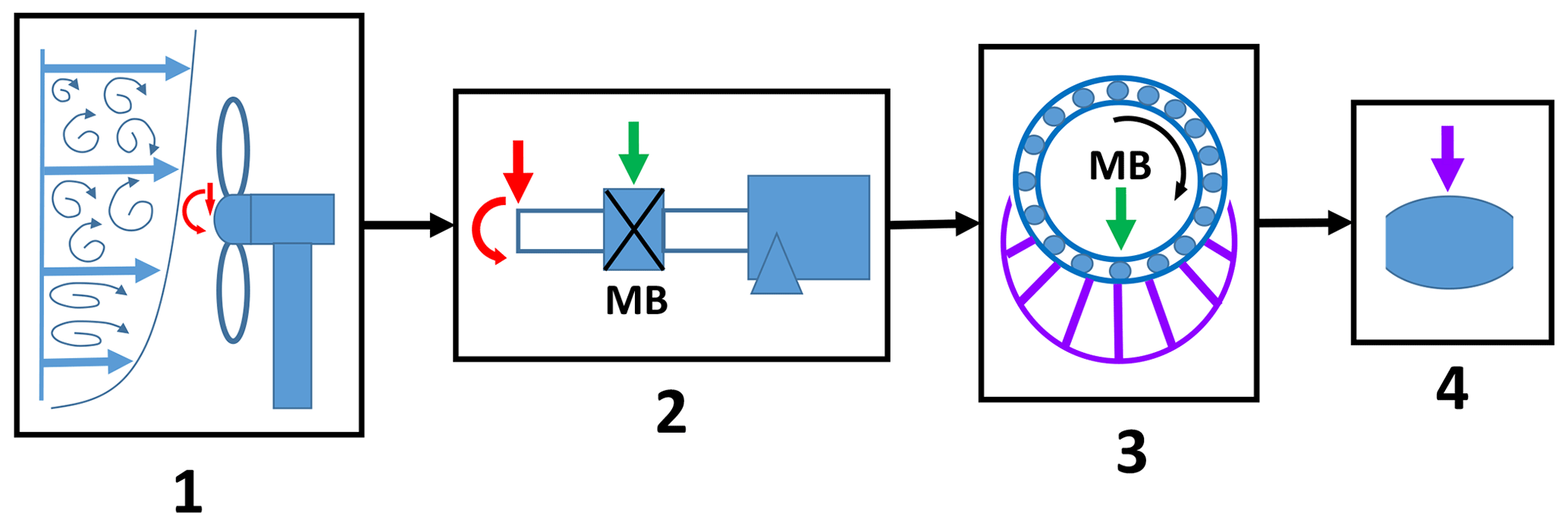
Figure 1Visual summary of the process by which the contact conditions dataset was generated. Starting from turbulent wind interactions, loads introduced to the system are resolved in the drivetrain and then inside of the main bearing. The resulting dataset captures the load acting at individual rollers within the main bearing, along with other information important to lubrication.
3.2 Main-bearing and lubricant data
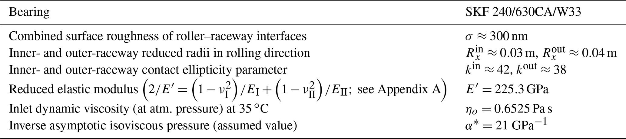
As described in Hart et al. (2022), lubrication analysis requires information relating to bearing geometry, surface roughness and lubricant properties. The modelled bearing is an SKF 240/630CA/W33, which is used for wind turbines of the size being simulated in this work. Some of its geometric information is available in the public domain; however, other details are not, and so approximate values only will be given in those cases. The lubricant which will be modelled in the current analysis is an industrial grease, specifically designed and marketed as a lubricant for wind turbines of this size, including for main bearings. Table 1 presents information relating to this bearing and the grease base oil; approximate values are given where necessary. Kinematic viscosity information of the base oil, from the grease manufacturer, was provided at 40 ∘C (460 mm2 s−1) and 100 ∘C (16 mm2 s−1) along with the relative density (0.9), as is standard. Interpolation to other temperatures was performed using the ASTM-prescribed method (ASTM, 2020). The inverse asymptotic isoviscous pressure, α*, of the main-bearing grease base oil is not known. In Vergne and Bair (2014) a range of measured α* values are listed. At a temperature of 40 ∘C, reported measured values have a mean value plus–minus standard deviation range of GPa−1. While α* is temperature dependent, it will not vary much for small differences in temperature (on the order considered here; see Vergne and Bair, 2014). A value of GPa−1 is therefore assumed, this being the best available estimate without more information. The sensitivity of results to the α* value will be considered as part of the analysis. Effects related to grease ageing and re-greasing (Lugt, 2013) were not considered in this analysis.
3.2.1 Operating temperatures for the main bearing
Operating temperatures will strongly influence lubricant viscosity, which in turn has a significant effect on lubricant film thickness (Hart et al., 2022). The simulation software and models used to evaluate contact conditions in the current work do not model or predict operating temperatures. It is therefore necessary to identify an appropriate temperature range over which to consider main-bearing lubrication. Based on published temperature data for main bearings in the literature (de Mello et al., 2022; Beretta et al., 2021), normal operation of healthy main bearings can be seen to include temperatures of around 20–40 ∘C as standard, with higher temperatures occurring if a fault develops. These temperature values reported in the literature relate to measurements taken on the outside of the bearing casing, as opposed to inside of the main bearing. Lubricant contact-inlet temperatures may therefore be higher than the values listed above. Preliminary analyses, during the course of this work, revealed that an important transition in lubrication regime occurs at around 35 ∘C for the modelled main bearing and lubricant. Therefore, the analysis presented here will be centred on this value, with results for higher- and lower-temperature cases of 40 and 30 ∘C, respectively, also given. It is again emphasised that, based on published data, explored temperatures fall within the standard operating temperature range of healthy main bearings. For analysis at a given temperature, that same temperature is assumed to hold across all operating points in the contact conditions dataset. Temperatures in the main bearing will vary during operation as a result of frictional effects and internal load and speed interactions. However, significant thermal inertia is present (de Mello et al., 2022), meaning only relatively weak correlations exist between load, speed and temperature measurements. As such, each operating point may be seen at a range of operating temperatures, indicating that the application of lubrication equations across all operating points while using a single fixed temperature does provide a valid, albeit simplified, assessment of conditions that will be seen in practise.
3.3 Lubrication analysis methodology
While highly sophisticated EHL solvers have been developed, as outlined in Hart et al. (2022), these tend to model individual contacts (as opposed to full bearings), and setting up and running these solvers is highly non-trivial. Prior to the application of such methods, it is sensible to first consider the problem using simplified lubrication equations and other results from EHL theory. This will provide immediate insight into main-bearing lubrication conditions and behaviour, allow the need for more advanced solvers in this space to be assessed, and help determine where more detailed investigations might be best focused. Therefore, in order to estimate surface separation within the main bearing, for conditions identified using the modelling approach outlined above, an appropriate minimum film thickness (hm) equation must be identified. In the present case, this includes determining whether roller–raceway contacts should be treated as line- or point-contact conjunctions. From Table 1, it can be seen that very high ellipticity values hold for contacts within the main bearing in question. In addition, the relative magnitudes of required adjustments to inner- and outer-raceway elasticity values when forming equivalent line-contact representations (Hart et al., 2022) were found to be negligible (around 0.1 %) for the modelled bearing. This indicates that roller–raceway contacts in this bearing are very close indeed to their equivalent line-contact counterparts, in the context of lubrication. Furthermore, the ellipticity values themselves far exceed those for which point-contact film thickness equations have been developed (Hart et al., 2022). It was therefore concluded that film thickness for this bearing should be analysed using the equivalent line-contact formulation, outlined in Hart et al. (2022), in combination with a line-contact film thickness formula. The formula selected for this analysis was the more recent and comprehensively fitted Masjedi and Khonsari line-contact equation (Hart et al., 2022; Masjedi and Khonsari, 2012). Given dimensionless roughness values of the main bearing in question, and , it follows that the associated rough-surface correction factor should also be used (Hart et al., 2022). Therefore, roller centre-line minimum film thickness values were estimated using
For definitions of all terms see Appendix A and Hart et al. (2022). Assuming normally distributed roughness, it follows that sstd=σ. Bearings of this type are hardened as much as possible, and so a value of V=0.03, corresponding to a high Vickers hardness of 700 HV which is typical for bearing steel, is used throughout. The lubricant entrainment velocity, , is calculated assuming pure rolling; see Appendix B. Recent work by Bergua et al. (2021), in which up-tower measurements from an operational wind turbine were found to show no appreciable levels of main-bearing gross slip, provides some justification for this assumption. In reality, some amount of individual roller slip would be expected to occur outside of the loaded zone, even in cases of no gross slip. Such effects are not accounted for in this analysis. However, the lack of gross slip observed for an operational main bearing (Bergua et al., 2021) indicates that the pure rolling assumption is likely valid throughout most of the loaded zone and, importantly, at the point of maximum load. Prior to lubricating film thickness results, contact pressures and dimensionless lubrication parameter values for the main bearing will be presented. As will be shown, operating parameter values for the main bearing lie well within the limits of where Eq. (1) was fitted.
Significant uncertainty is present regarding conditions inside of the main bearing which contribute to overall lubrication performance, especially due to the likely presence of starvation under grease lubrication (after the churning phase) (Hart et al., 2022). Lubrication was therefore investigated starting from a “best-case scenario” of fully flooded conditions, for which Eq. (1) is applied directly while assuming lubrication is driven by grease base-oil properties only. As discussed in Hart et al. (2022), it is not yet possible to easily predict starvation levels in full grease-lubricated bearings. Possible effects of starvation were therefore considered using a basic order-of-magnitude estimate of resulting film reductions. This was achieved by reducing film thickness predictions to 70 % of their fully flooded values. Based on the results of Masjedi and Khonsari (2015), this level of starvation coincides with a roughly 30 % reduction in lubricant mass flow rate through the contacts. To be clear, this treatment offers only a crude estimate of possible starvation effects which, in practise, will vary with speed and other parameters. For grease lubrication in particular, considerably more severe levels of starvation have been observed (Cen and Lugt, 2019, 2020). See Hart et al. (2022) for a more detailed discussion of this aspect of EHL. Both fully flooded and starved results will be presented for temperatures of and 40 ∘C, allowing the sensitivity of film thickness to operating temperature to be quantified. Roller load and α* value sensitivities were also investigated. The approach outlined thus far does not account for possible grease thickener interactions on film thickness values. The importance of this aspect of grease lubrication in the main-bearing case will therefore be considered by combining film thickness predictions, obtained here, with results reported in the literature concerning the onset of thickener interactions. The analyses outlined thus far all rely on the chosen film thickness equation, which applies in steady-state lubrication. Possible non-steady effects are therefore not accounted for, with the above therefore referred to as steady-state film thickness analyses. The possible presence of significant non-steady EHL effects during main-bearing operation is investigated in a subsequent analysis, by considering and values relative to the concurrent value of lubricant entrainment velocity, . A lower limit for significance is taken to be 25 %, based on findings reported in the literature (Hart et al., 2022; Hooke, 2003).
At this stage, it is not possible to quantify the accuracy with which the described lubrication analysis is able to represent lubrication conditions, behaviour and film thickness in a real-world main bearing. Results must therefore be interpreted with care, keeping in mind the related discussions in Part 1 of this work (Hart et al., 2022). However, this analysis should allow for general conclusions to be reached regarding the dominant lubrication regime(s), key film thickness sensitivities and the likely importance of more complex effects (starvation, thickener interactions and non-steady effects). This, therefore, is the context in which results should be approached and interpreted.
Lubrication analysis results will be presented in the current section. It is first important to revisit the approximations made during modelling stages. This includes the half-space approximation for contacting surfaces in EHL models used to generate film thickness equations, as well as the lubrication approximation applied in the same EHL models (see Hart et al., 2022). In addition, the outlined methodology analyses bearing internal loading and displacement independently of lubrication and lubricant film thickness values. Such an approximation is only valid if one does not significantly impact the other, more specifically, if roller deflections are significantly larger than film thickness values. Assessing the appropriateness of these approximations, in the current case, therefore requires model geometries and outputs to be compared. Such an analysis was undertaken, confirming (as far as is possible without more complex analyses) that all requirements are met with regards to ensuring modelling approximations may be considered valid. The analysis itself is presented in Appendix C.
4.1 Lubrication conditions
Prior to film analysis itself, it is necessary to consider the conditions (with respect to dimensionless parameter values) under which lubricated conjunctions within the main bearing are operating. This allows for the extremity of conditions to be assessed, while also providing an indication of the validity of the chosen film thickness equation. As outlined in Sect. 3.3, the main-bearing analysis was conducted while treating main-bearing point-contact conjunctions as equivalent line contacts. Dimensionless parameters in this case are therefore those of the equivalent line contacts. Moes' load and viscosity parameter values (Ml and L, Hart et al., 2022) were calculated across the contact conditions dataset at each investigated temperature. Figure 2a shows the dimensionless parameter results at 35 ∘C, along with dimensionless parameter “fitting region limits” for the selected film thickness equation (see Hart et al., 2022). Both inner- and outer-raceway parameters are plotted, with considerable overlap occurring between the two. Points in the plot are coloured according to the wind turbine rotor mean wind speed occurring at that point in time.
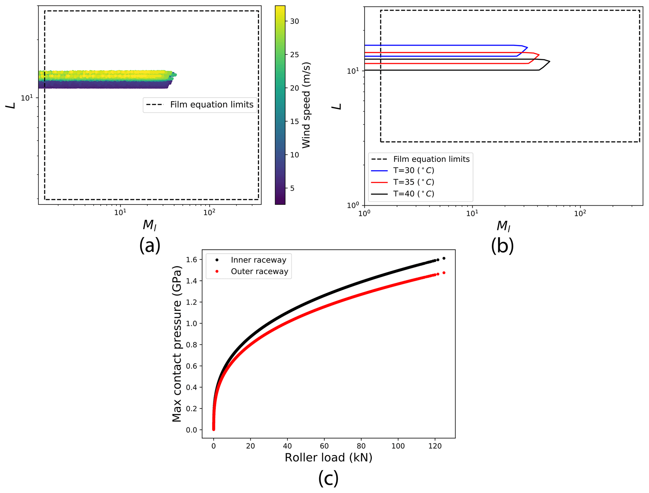
Figure 2Lubrication conditions, in the form of dimensionless parameter values and maximum Hertzian pressures within contact conjunctions. Panel (a) shows dimensionless parameter results at 35 ∘C for both inner and outer raceways; (b) the contact condition point boundaries for temperatures of 30, 35 and 40 ∘C; and (c) the maximum contact pressures from across the dataset.
The range of viscosity parameter (L) values visited during main-bearing operation can be seen to be small. In particular, the values of L at inner- and outer-raceway contacts correlate strongly with wind speed. This relationship stems from the turbine operating strategy, in which rotational speed increases with wind speed (until nearing rated power) in order to maintain aerodynamic efficiency (Hart et al., 2020). Variations in load parameter values (Ml) are considerably higher, with Ml uncorrelated to wind speed. Both observations are unsurprising, given that significant load variation around the bearing circumference will be present (Hart, 2020) – generally including an unloaded region. Each roller traversing the bearing circumference therefore experiences continuous variations in loading from minimum (possibly zero) to maximum (in terms of roller loads around the circumference at a given point in time) levels. Thus, observing a wide range of dimensionless load parameter values at each wind speed would be expected. With respect to the fitting region limits of the chosen film thickness equation: dimensionless viscosity parameter (L) values can be seen to lie well within the range over which the equation was developed; dimensionless load parameter values (Ml) also lie within their associated limits for the vast majority of points in the contact conditions dataset. Indeed, fitting region limits are only passed in the low-load region as wl→0, and so Ml→0. It should be noted that outlying points at very low loads correspond to high values of steady-state film thickness.3 In the context of lubrication analysis, it is regions of potentially low film thickness that are of primary interest, hence not around wl≈0. As may be seen in the figure, all higher values of the dimensionless load parameter fall well within the limits of the applied film equation. To avoid erroneous results from extremely small load parameter values (the smallest of which are on the order of 10−5), all results presented in subsequent sections exclude cases where w<1 kN. Given the operating speeds of the modelled turbine, this limit ensures Ml≥1.4, with all presented results for parameter values therefore falling within or very close to the boundaries shown in Fig. 2a. In Hart et al. (2022), literature misrepresentations of the parameter ranges over which the Masjedi and Khonsari point-contact equation was fitted were described. It is pertinent to note that with regards to point-contact dimensionless parameters (L and M), operating points in the current dataset also fall well within the point-contact fitting region limits at higher load levels, but this appears not to be the case if the incorrectly reported limits are used. While the point-contact equation is not applied here, for reasons which have been outlined, this example demonstrates the need for fitting region limits to be checked, while also ensuring that the correct limits are applied.
Lubricant contact-inlet temperature is known to be a strong driver of viscosity and, hence, of dimensionless parameter values and film thickness (Hart et al., 2022). The impact of temperature variations on dimensionless parameter values was therefore considered. Figure 2b shows boundaries of operating point sets (more specifically their convex hulls) obtained from the contact conditions dataset at temperatures of and 40 ∘C. Increases in temperature can be seen to increase Ml values and decrease L values across the operational dataset. The effect is reversed for a decrease in temperature. Observations made earlier in the current section can be seen to remain valid at each temperature considered.
Finally, contact pressures within main-bearing contact conjunctions were considered by approximating maximum EHL pressure values as those occurring under equivalent dry Hertzian contact (see Hart et al., 2022). By construction, the maximum pressure within point and equivalent line-contact representations of the conjunctions is equal (Hart et al., 2022). For inner- and outer-raceway contacts Fig. 2c shows maximum contact pressure values, plotted against roller applied loads, for all points in the contact conditions dataset. Surprisingly, these values are lower than might be expected given the high magnitude of loads reacted by the main bearing (Hart, 2020). For bearings of this type, the rated load level will sit at around 2.5–3 GPa. As shown in the figure, maximum contact pressures, obtained from the modelling undertaken here, all lie comfortably below these limiting values. The perhaps modest pressure levels seen here are likely due to the combined effects of low y direction curvature at contact interfaces4 and a relatively large number of rollers, 27, in each row. More complex internal effects such as roller unseating and skewing are not modelled here; therefore, higher levels of pressure could occur in practise as a result of such interactions.
The presented lubrication condition results indicate that, having applied the restriction w>1 kN, operating points fall such that the chosen film thickness equation is appropriate for performing a steady-state analysis of film thickness for this main bearing. Note, the standard caveats regarding the accuracy and interpretation of results obtained from simplified film thickness equations (as discussed in Hart et al., 2022) still apply. Contact pressure results indicate that, with respect to the effects modelled currently and assuming maximum pressures are well approximated by the Hertzian value, bearing material ultimate-strength limits are not being exceeded during operation.
4.2 Steady-state film thickness analyses
Having identified an appropriate low load cut-off and confirmed suitability of the chosen equation, steady-state film thickness analyses were undertaken as described in Sect. 3. The results of these analyses will now be presented.
4.2.1 Fully flooded results
Figure 3a shows film parameter, , values obtained for operating points in the contact conditions dataset with T=35 ∘C. Shaft speed and roller load values are also plotted. Note, shaft speed is proportional to the lubricant mean entrainment velocity, , since pure rolling is assumed (see Appendix B). Inner raceway points are plotted individually, whereas, for the sake of clarity, the overlapping outer-raceway results are summarised via their convex hull. Focusing on inner-raceway results, Λ values can be seen to fall between 2.7 and 5.1, with a mean value of 3.8. As would be expected from the exponents in film equations, as well as the results of EHL theory more generally (Hart et al., 2022), film thickness values are strongly driven by rotational speed at all load levels. Variations in film thickness with load also show a relatively wide spread, but closer inspection reveals that most of this variation occurs at low roller loads (w→0). Film thickness sensitivity to load falls dramatically as roller load increases. As indicated earlier, this is expected from general EHL results (Hart et al., 2022). Note also that the smallest loads are generally experienced as rollers move towards the edge of the loaded zone (Hart, 2020), which itself may move, while traversing the bearing circumference. Each roller will therefore pass through a wide range of load levels and Λ values during each orbit. Outer-raceway results are qualitatively similar, but offset by a small amount in the positive Λ direction relative to those of the inner raceway. Since pure rolling is assumed, values are identical at inner and outer raceways (see Appendix B). Therefore, the observed film thickness differences at inner and outer raceways result from differing geometries at the respective contacts. With respect to the lubrication regimes associated with Λ values (Hart et al., 2022), for fully flooded operation at T=35 ∘C, both inner- and outer-raceway contacts are predicted to operate mainly in the elastohydrodynamic regime (Λ>3), with some small amount of time spent in the mixed lubrication regime ().5 From Fig. 3a, it is evident that the key factor (under fully flooded conditions) determining the lubrication regime, and possible transition to mixed lubrication, is the shaft speed, with the least favourable conditions occurring at low speeds.
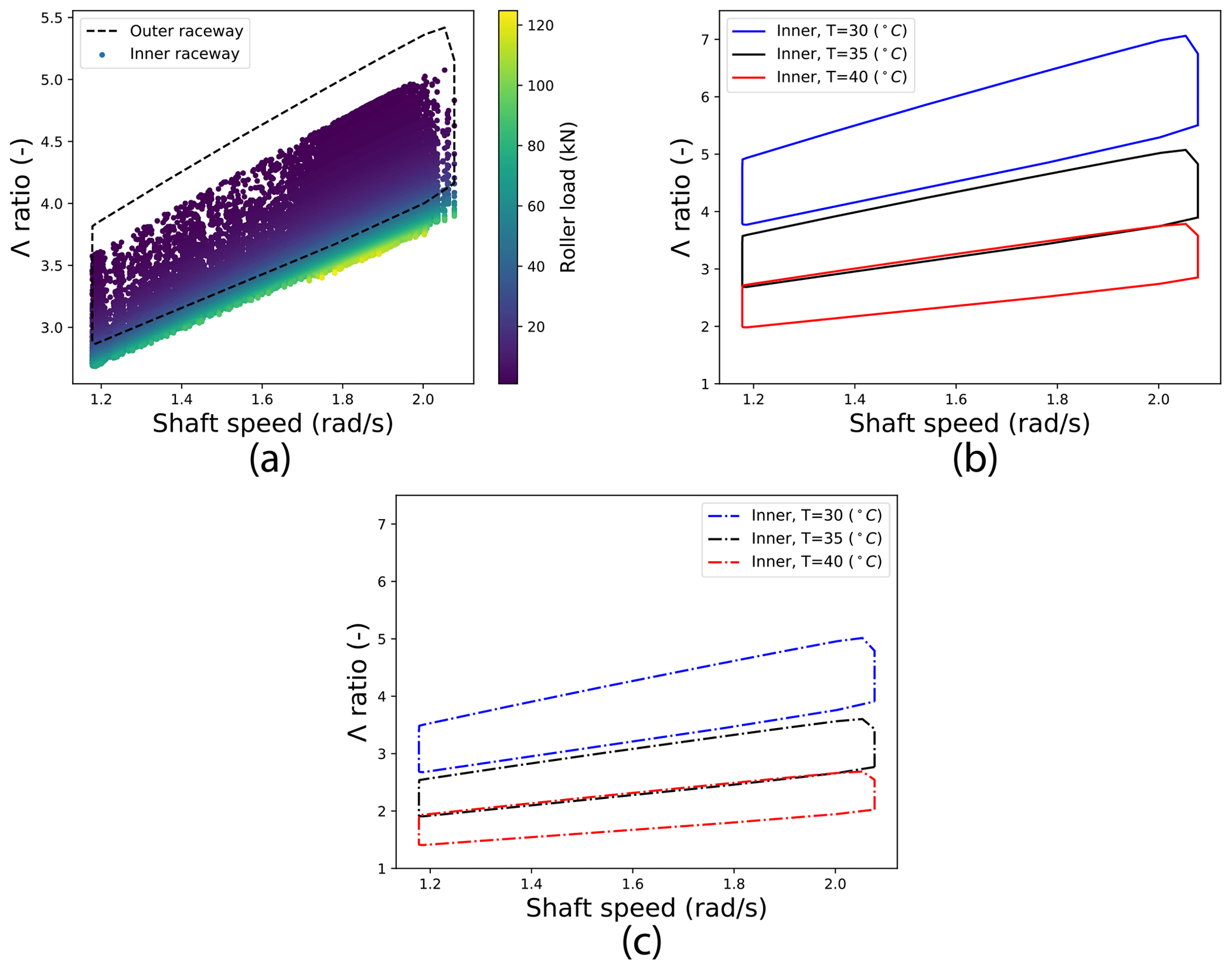
Figure 3Steady-state dimensionless film thickness (Λ) results. Panel (a) shows inner- and outer-raceway results at T=35 ∘C, (b) shows inner-raceway results when T is varied and (c) shows the same results having applied a crude order of magnitude estimate of the effect of starvation.
Figure 3b shows the effect of temperature variations on film thickness, with inner-raceway Λ-value boundaries plotted from results obtained at contact-inlet temperatures of and 40 ∘C. As would be expected, from lubricant viscosity behaviour, a reduction in operating temperature leads to an increase in film thickness, while reduced film thickness values are seen when the temperature is increased. From the point of view of the lubrication regime, impacts of these relatively modest changes in temperature are dramatic. A reduction in temperature of 5 ∘C can be seen to draw results well into the elastohydrodynamic regime and even into possible hydrodynamic lubrication. On the other hand, an increase of 5 ∘C draws results significantly into the mixed lubrication regime, with 79 % of operating points having Λ<3. With respect to fully flooded results, the operating temperature T=35 ∘C therefore represents an important transition point (for the modelled main bearing and lubricant) in terms of operational lubrication regimes.
4.2.2 Starved results
Main bearings are grease lubricated and, therefore, expected to be operating under starved conditions throughout most of their operational lifetimes (Hart et al., 2022). As detailed in Sect. 3.3, a crude order of magnitude estimate of the impact of starvation on main-bearing lubrication was obtained by taking 70 % of the fully flooded Λ values. The effect of this is shown in Fig. 3c. As with temperature variations, the impacts here are significant, with all operating points at T=40 ∘C now well into the mixed lubrication regime and beginning to approach boundary lubrication (Λ<1). For results at T=35 ∘C, 88 % of operating points are now in the mixed regime. Starvation levels in operational main bearings are not yet known and, in reality, will vary with the operating conditions. However, much higher levels of grease starvation than that applied here have been observed in practise (Hart et al., 2022). Therefore, the results in Fig. 3c could still be providing an optimistic view of main-bearing lubrication.
4.2.3 Grease thickener interactions
As described in Part 1 of this study (Hart et al., 2022), at film thicknesses below a level related to the size of thickener fibres/fibre networks, the thickener interacts with the contact conjunction, altering film thickness behaviour such that it can no longer be estimated using oil lubrication formulas and properties of the grease base oil. Determining if such effects may be present for the modelled main bearing therefore requires estimated film thickness values to be compared with a suitable “transition thickness”, above which base-oil effects would dominate and below which the film behaviour would be driven by thickener interactions. Such a value is not directly known for the main-bearing grease considered here. Instead, results reported in the literature are used to identify a sensible range for such a transition thickness. In Cen et al. (2014), Morales-Espejel et al. (2014) and Kanazawa et al. (2017), grease thickener interactions are investigated for a number of different greases; in the first study, the impact of the grease being mechanically worked is also assessed. From results presented in these previous studies, maximum observed values6 of the transition film thickness sit at around 100 nm. Transition values, along with the relative magnitude of thickener effects, reduce as the grease is worked, with worked grease transition thicknesses of around just 10 nm seen in some cases. It is therefore proposed that a reasonable range in which to assume the transition thickness lies, for this main-bearing grease, is between 10 and 100 nm. From Table 1 σ≈300 nm, and so Fig. 3 results (in terms of Λ) can be converted to approximate film thickness values using nm. Therefore, Λ=3 corresponds to a film thickness of hm≈900 nm and Λ=1 corresponds to hm≈300 nm. Across all results presented here, as well as for more severe cases of starvation than that considered, film thickness values remain significantly higher than the maximum value in the identified (approximate) range for transition film thickness. Based on the currently available information, a tentative conclusion is therefore reached, this being that it appears unlikely that grease thickener interactions significantly impact lubrication in the modelled main bearing. This result also implies that, at present, there is no reason to assume that oil-based film equations, such as the one applied here, are not able to provide sensible estimates of lubrication behaviour in this setting. As ever, the normal caveats regarding the accuracy of such equations remain (see Hart et al., 2022). It is emphasised that these conclusions are tentative. For example, if fibre and/or fibre-network dimensions in main-bearing greases are significantly larger than those of greases used in the cited literature, a different conclusion might result. Furthermore, surface roughness may also influence the point at which grease fibre interactions begin to influence lubrication behaviour. In Cen et al. (2014) and Kanazawa et al. (2017) surface roughness values are such that Λ ratios are consistently greater than 1, never falling much below this value if at all. If starvation is really quite severe for the main bearing, Λ values less than 1 are possible. In this case, it is not clear how operation inside of the boundary lubrication regime might impact grease interactions. Finally, it is important to note that the cited studies all ensure fully flooded inlets at all times. While the discussion has thus far centred mainly on film thickness values/ratios, it may also be the case that starvation impacts the likelihood of grease fibre interactions in other ways, for example by altering the quantity of thickener fibres available to the conjunction or influencing the deposition of degraded grease onto bearing surfaces (Hart et al., 2022). Much uncertainty therefore remains with respect to this particular aspect of the problem.
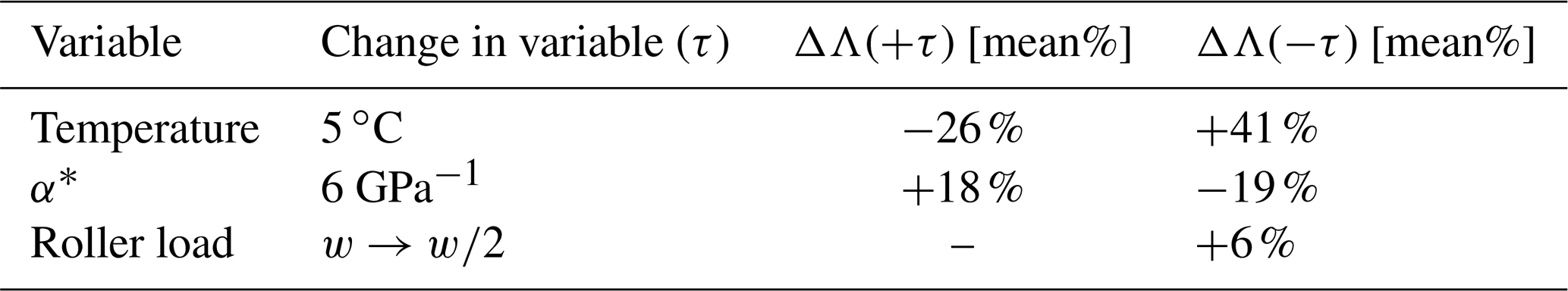
The presented steady-state results provide important insights into the lubrication problem for wind turbine main bearings. However, it should be remembered that certain approximations and assumptions are present in the applied model and chosen lubricant properties. The sensitivity of results to variable values associated with these sources of uncertainty was therefore considered. Sensitivity, with respect to Λ values, was assessed for the variables of temperature (T), inverse asymptotic isoviscous pressure (α*) and roller load (w). Temperature was considered as part of the above analysis, where it was found that its effect is significant. The true α* value for the modelled lubricant is unknown and so an assumed value was used. The sensitivity to changes in this variable will indicate how critical it is to ensure an accurate value is known. Finally, as outlined in Sect. 2, results in the literature indicate that Hertzian models of the type applied here may result in over-estimations of the roller loads around the bearing circumference. In order to determine possible impacts of this on lubrication results, the effect of reducing load levels was also tested. The “standard case” was taken as being Λ values calculated for T=35 ∘C and GPa−1 and with load values unaltered. Each variable was then adjusted independently to determine its effect on Λ values. For temperature, variations of ±5 ∘C were applied; for α*, variations were ±6 GPa−1 (see Sect. 3.2); for w the effect of all roller loads being halved was determined. Graphical results for temperature variations have been shown above, and those for roller load and α* variations can be found in Appendix D. Table 2 summarises the results of the sensitivity analysis, showing the mean percentage change to Λ values (across the full contact conditions dataset) resulting from the specified changes to each variable. Temperature is the most sensitive of the tested variables and, in practise, will vary quite considerably during operation. A change of α* value is also impactful with respect to estimated film thickness values. Determining accurate/appropriate values for this parameter will therefore be important in future main-bearing lubrication studies. Interestingly, and as might be expected from classical EHL theory, the results are insensitive to variations in loading. A 50 % reduction in loads elicits only a 6 % increase in Λ values on average. This indicates that potential concerns related to modelled internal loads (see Sect. 2) are unlikely to have much influence on EHL findings. That is not to say that load levels and load distributions are not relevant to main-bearing lubrication, a point which will be revisited in Sect. 5. Starvation should also be considered in the context of these sensitivity results since it likely has a relative impact on the order of 30 % or more, with true values unknown but potentially quite high. Based on the above, key sensitivities for main-bearing lubrication are concluded to be contact-inlet temperatures, starvation levels and the grease base-oil α* value.
Table 2Summary results of the sensitivity analysis. Mean percentage changes to Λ values, resulting from specified changes to each variable's “standard value”, are given.
4.3 The significance of non-steady effects?
Considerations of possible non-steady effects will be undertaken treating the point contacts as such, as opposed to using the equivalent line-contact representation, which (as discussed) was necessary when estimating film thickness values. As described in Sect. 3.3, the possible presence of non-steady EHL effects was investigated by considering contact patch time rate-of-change values in rolling and transverse directions ( and , respectively) relative to the concurrent value of mean entrainment velocity (). The relevance threshold is taken to be 25 % (Hart et al., 2022; Hooke, 2003). Results at inner and outer raceways are almost identical, and so only inner-raceway results are shown here. Figure 4 shows contact conditions dataset values of , where , plotted against roller load. As previously, results are only shown where roller loads exceed 1 kN. Considering these results, it is clear that values fall well below the 0.25 value, which would signify the possible presence of significant non-steady EHL effects. Indeed, the estimated values are at least an order of magnitude out from this. Rolling direction non-steady effects, of the type considered, are therefore not expected to be occurring for the modelled main bearing. Figure 5a shows contact conditions dataset values of , where , plotted against roller load. In contrast to the behaviour seen in rolling direction results, transverse direction ratio values are considerably higher, with a significant number of points lying below −0.25 and above 0.25. This is attributable to the high level of conformity between rollers and raceways in this direction, meaning contact conjunction edges move rapidly outwards or inwards as the applied load varies. With regards to film thickness and bearing damage, it is negative ratio values which are of interest; this is because it is when load is rapidly removed (and so the contact patch shrinks) that local reductions in film thickness are known to occur, increasing the risk of damage (Hart et al., 2022). Figure 5a therefore includes a vertical dashed line indicating the location of the −0.25 threshold. A close-up of data falling to the left of this line is then shown in Fig. 5b. Various features of these plots are worth considering, the most immediately evident being that maximum observed ratio values (in terms of magnitude) reduce as roller load increases. This is expected from the Hertzian equations: since (where w is roller load), it follows that , a quantity for which the same value of seen at a higher load elicits a smaller response. The implication of this behaviour is that the possibility of non-steady effects is highest for lower values of roller load, with the largest ratio values seen close to the smallest loads (above the 1 kN cutoff). However, values less than −0.25 can still be seen to occur at moderate levels of applied loading, including one for which w=12.5 kN. Since the contact conditions dataset represents only a subset of the simulation data, which itself contains a total of 30 10 min duration simulations, higher load values in this region could well be possible. Presented results therefore indicate that transverse direction non-steady EHL effects are predicted to be taking place, but at loads in approximately the lowest 10 % of those observed across the operational envelope. The impacts of such effects on the lubrication film and possible damage resulting are not yet known. Furthermore, non-steady effects are predicted to occur in the transverse, as opposed to rolling, direction. Very little, if any, work has been undertaken which investigates EHL in these circumstances. While consideration has been given to side-leakage effects associated with ellipticity (Wheeler et al., 2016; Damiens, 2003), the authors are unaware of any work which considers transverse direction (only) non-steady behaviour. This may be due to the relatively unique conditions experienced by wind turbine main bearings, meaning such behaviour in rolling element bearings may not have been observed/predicted before now.
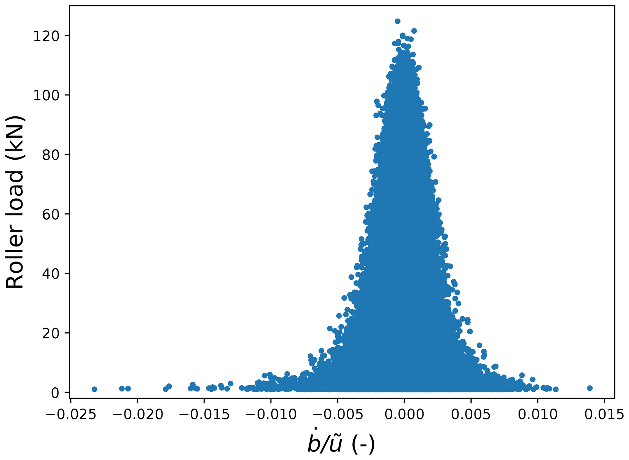
Figure 4Inner-raceway (for in the direction of rolling), where , with values plotted against roller load. Results are only shown where roller loads exceed 1 kN.
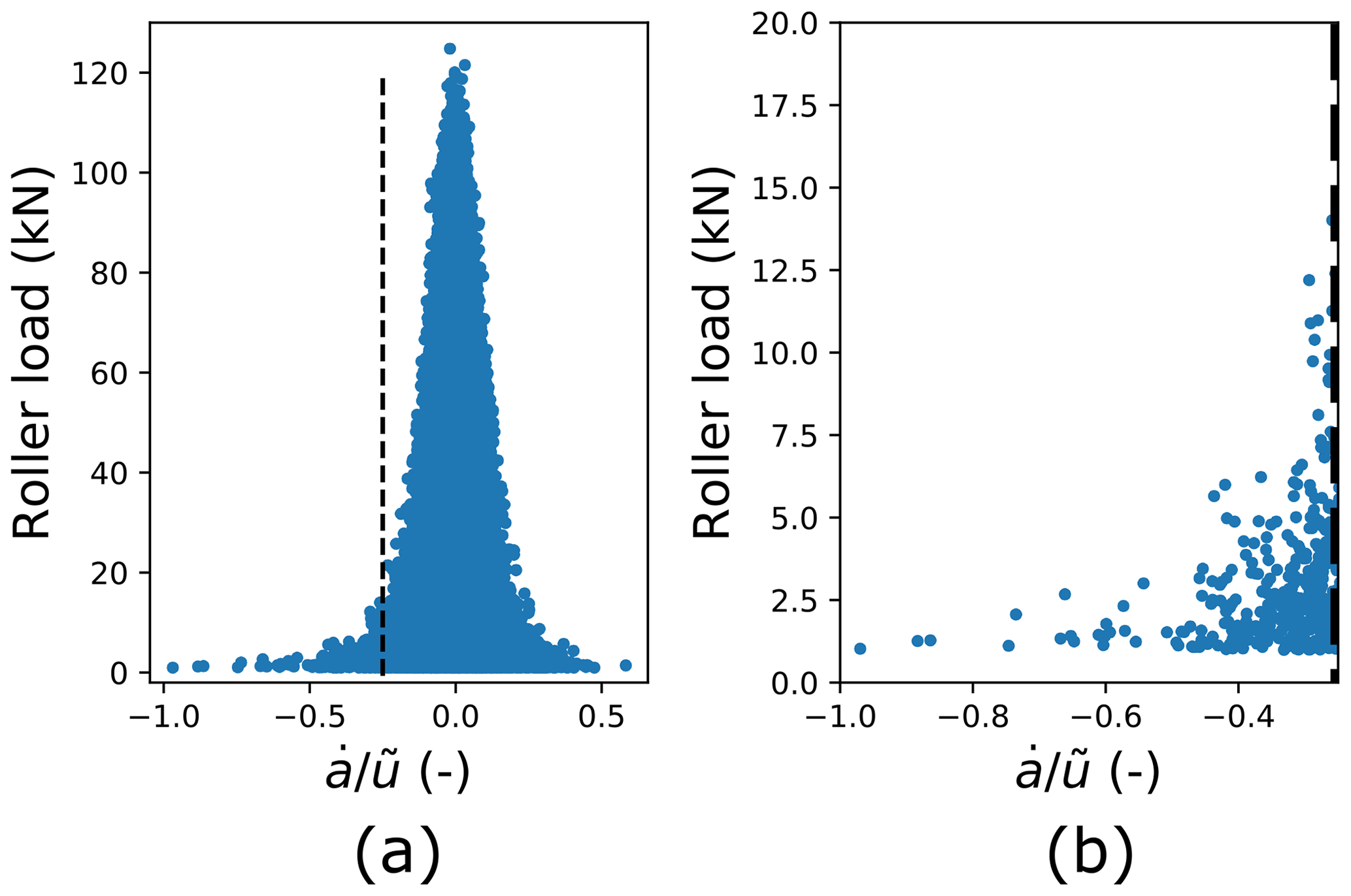
Figure 5Inner-raceway (for transverse to the direction of rolling), where , with values plotted against roller load. Results are only shown where roller loads exceed 1 kN. Panel (a) shows all results, with a vertical dashed line included to indicate the −0.25 threshold for potentially damaging non-steady effects. Panel (b) provides a close-up of data falling to the left of this threshold.
It is emphasised that there is uncertainty present in these results due to modelling approximations and assumptions, as well as the use of finite differencing to estimate gradients. In particular, possible sliding and skewing behaviour in a real main bearing will influence mean entrainment velocity values, , along with the time variations in load and pressure seen by each roller. Influences of main-bearing housing elasticity, not accounted for in this model, may also alter the magnitude and distribution of load around the bearing. Note, due to the relationship, inclusion of housing elasticity could lead to increases or decreases in non-steady behaviour, and so more work would be needed to determine its effect. Finally, further work is required to understand the interaction of predicted non-steady effects with the grease thickener in a likely starved full roller bearing. In particular, it is necessary to consider what the effects of rapidly elongating contact patches (transverse to rolling) may be with regards to the dispersion/distribution of grease and bled oil, in the context of both individual contacts and throughout the main bearing as a whole.
There is much to unpack in the results which have been presented. A summary of key findings is therefore provided prior to further discussion.
-
The spherical roller main-bearing contacts in question should be treated as equivalent line contacts for the purposes of film thickness analysis using simplified lubrication equations.
-
When treated as such, lubrication conditions (in terms of dimensionless parameters) fall well within the region over which the applied equation was fitted (except at the very lowest load levels).
-
Maximum pressures estimated to occur in the contact conjunctions were lower than might be expected, with values not exceeding about 1.6 GPa. More complex effects, not accounted for here, could lead to the occurrence of higher pressure values than have been estimated. In particular, it was assumed that maximum pressures may be well approximated by the maximum Hertzian values.
-
In a best-case scenario of fully flooded lubrication, T=35 ∘C was found to represent a transition point between EHL and mixed lubrication regimes. By T=40 ∘C, close to 80 % of fully flooded operating points fell into the mixed lubrication regime.
-
Since main bearings are grease lubricated, starved conditions are expected to be present, but levels of starvation are unknown. An order of magnitude estimate of possible starvation effects (a 30 % reduction in film height) was applied, the effect of which was dramatic in the context of lubrication regimes. Under the assumed level of starvation, close to 90 % of operating points for T=35 ∘C fell into the mixed regime, along with all operating points for T=40 ∘C. Importantly, more severe levels of starvation could be present in real wind turbine main bearings.
-
A sensitivity analysis revealed that results were most strongly impacted by the contact-inlet temperature, starvation level and α* value. The effect of roller load on film thickness results was small.
-
Comparing presented results with available information in the literature, it was tentatively concluded that significant levels of grease-thickener interactions (with the contact conjunction) appear unlikely for the modelled main bearing.
-
Non-steady EHL effects were predicted to be negligible in the direction of rolling, but potentially of significance in the transverse direction. Possible non-steady effects in this latter case were found to occur at lower loads, with observed maximum values around 12.5 kN.
As has been emphasised, uncertainties are present, which means that care must be taken when interpreting these findings. In particular, further work is needed to better understand properties related to key sensitivities, these being temperature, starvation and α* values, for wind turbine main bearings and their lubricating greases. Furthermore, while presented results indicate lubricating films are only weakly sensitive to load, loading behaviour could still prove to have a significant but indirect effect. Specifically, it will be important to consider whether the highly variable and structured loading experienced by main bearings (Hart, 2020) may influence grease dispersion/distribution within the bearing and/or frictional behaviour such that starvation levels and contact-inlet temperatures are impacted. It will also be necessary to determine the impact of effects not accounted for here, including housing and bedplate flexibility and dynamic roller behaviour (sliding, skewing, etc.). The presence of individual roller sliding/slip, through the unloaded zone, could result in high levels of friction as the roller re-enters the loaded zone and is accelerated back to pure rolling. While slip is not expected to strongly influence film thickness values directly (Crook, 1961), increases in frictional energy may influence the temperature of the bulk lubricant in the main bearing. Where a roller is sliding, non-Newtonian lubricant properties, such as shear thinning, may become more important (Bair, 2005). Non-steady EHL effects in the main bearing also warrant further attention, especially when considering that transverse-direction-only non-steady effects are not believed to have been studied in detail previously. Finally, future work should also consider possible effects from intermittent wind turbine operation and cold starts on lubrication.
At this stage, it is not clear how the results of this analysis might change for larger wind turbines. Indeed, it is difficult even to speculate. While larger wind turbines will experience increased load magnitudes and generally rotate more slowly7, the main bearing will likely be of greater diameter and contain more rollers. The former will increase roller loads and decrease entrainment velocities, while the latter tend to have opposite effects. The overall drivetrain design, including the main bearing(s), may also be quite different for larger wind turbines. Lubrication conditions in larger turbines will therefore ultimately be determined by the interplay of these various factors.
The modelled main bearing, in estimated starved conditions, was predicted to experience some proportion of time operating in the mixed lubrication regime for all temperatures of T≥30 ∘C. If starvation is more severe in reality, mixed lubrication may begin at lower temperatures. These findings imply that the modelled main bearing would be operating under increased levels of friction and a heightened risk of wear and micro-pitting for a non-negligible proportion of its operational life. This result has clear implications for the likelihood of damage associated with such conditions.
With all described caveats in place, it is concluded that further development of the scientific understanding of lubrication in wind turbine main bearings is a necessary part of ongoing efforts to identify and understand key drivers of the observed high rates of failure for this component.
The mean entrainment velocity, , is given by (Hart et al., 2022)
where uI and uI are surface velocities of bodies I and II (roller and raceway, respectively) in the direction of rolling. These velocities are dependent on shaft speed and system geometry. Figure B1 shows the cross section of a roller orbiting the bearing centre in fixed and rotating reference frames, the latter moving with the roller centre. and are the perpendicular distances between the axis of rotation and inner- and outer-raceway contact centres (see Hart, 2020). Expressions for surface velocities may be derived as follows: assuming pure rolling, inner and outer contact surface tangential velocities must be equal (uI=uII); hence
for ωr, Ωi and Ωc the angular velocities shown in Fig. B1 and rroll the roller centreline radius. From this it follows that
Since uI=uII,
Entrainment velocities for inner and outer contacts can be seen to have equal magnitude but opposite direction in the applied frame of reference. Since lubrication is considered locally at each contact location, directional differences in the global reference frame are not relevant. Entrainment velocities at inner and outer raceways may therefore be considered equal, with both given by
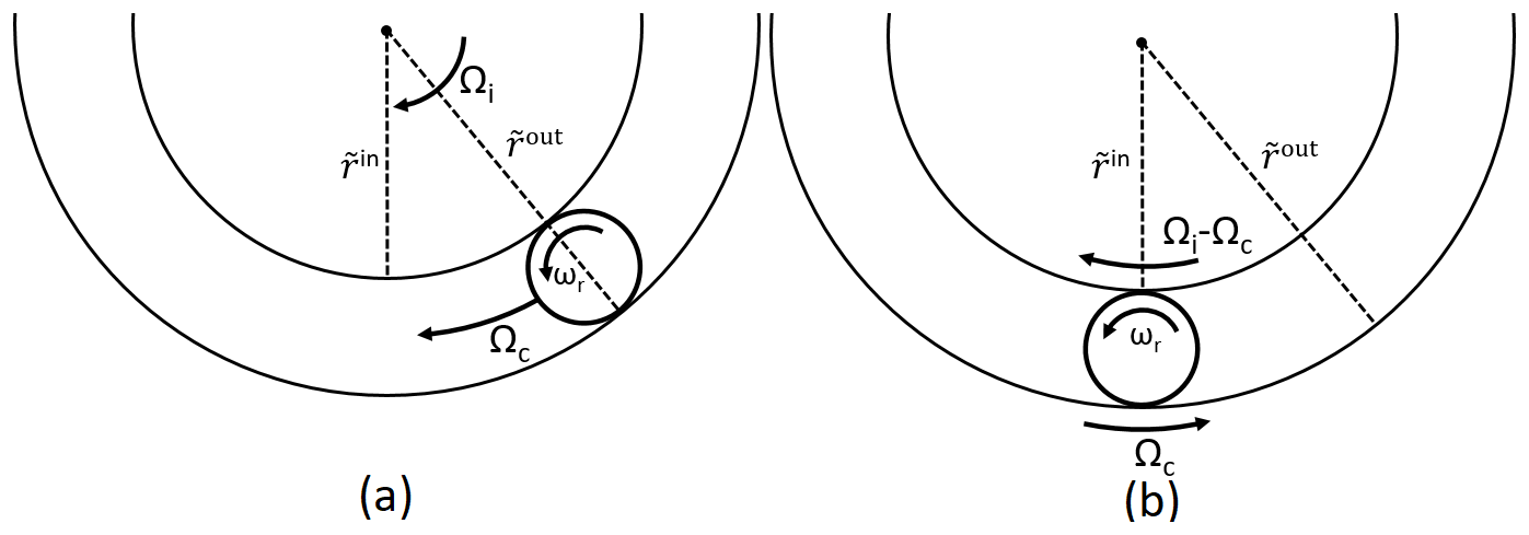
Figure B1Roller orbiting bearing centre with respect to (a) stationary and (b) rotating reference frames; in the latter case the position of the roller centre remains fixed. Ωi and Ωc describe angular velocity with respect to the bearing centre, and ωr describes angular velocity with respect to the roller centre. Note the axis around which ωr is defined is tilted by the contact angle, α, relative to the Ωi and Ωc axes.
Outputs were checked to provide confidence in the validity of approximations applied at modelling stages. For a more detailed discussion of the approximations themselves, see Hart et al. (2022). With regards to contact dimensions and curvature radii, values of at inner and outer contacts never exceed 3 %, and values of never exceed 0.3 %. Figure C1 shows values of and , where δ is roller deflection as given by Hertzian equations (see Hart, 2020), seen across the contact conditions dataset. These results show that maximum values are around 6 %, but only at very low loads. At higher loads these values fall rapidly to around 0.2 % and lower. From the results it follows that everywhere , with the results therefore providing an upper limit for ratios involving these other contact dimensions. results directly demonstrate the validity of evaluating internal deflections and loading independently of lubrication, especially considering the results seen here for more highly loaded rollers, since it will be these rollers which have the most influence on the resulting internal loads and displacements at each time step. From analysis of the presented results, it may also be concluded that the “half-space” and “lubrication” approximations may be considered valid here.
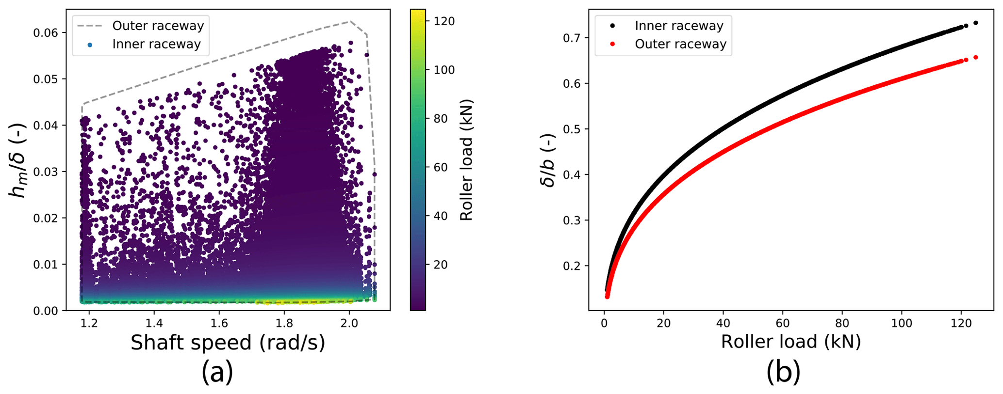
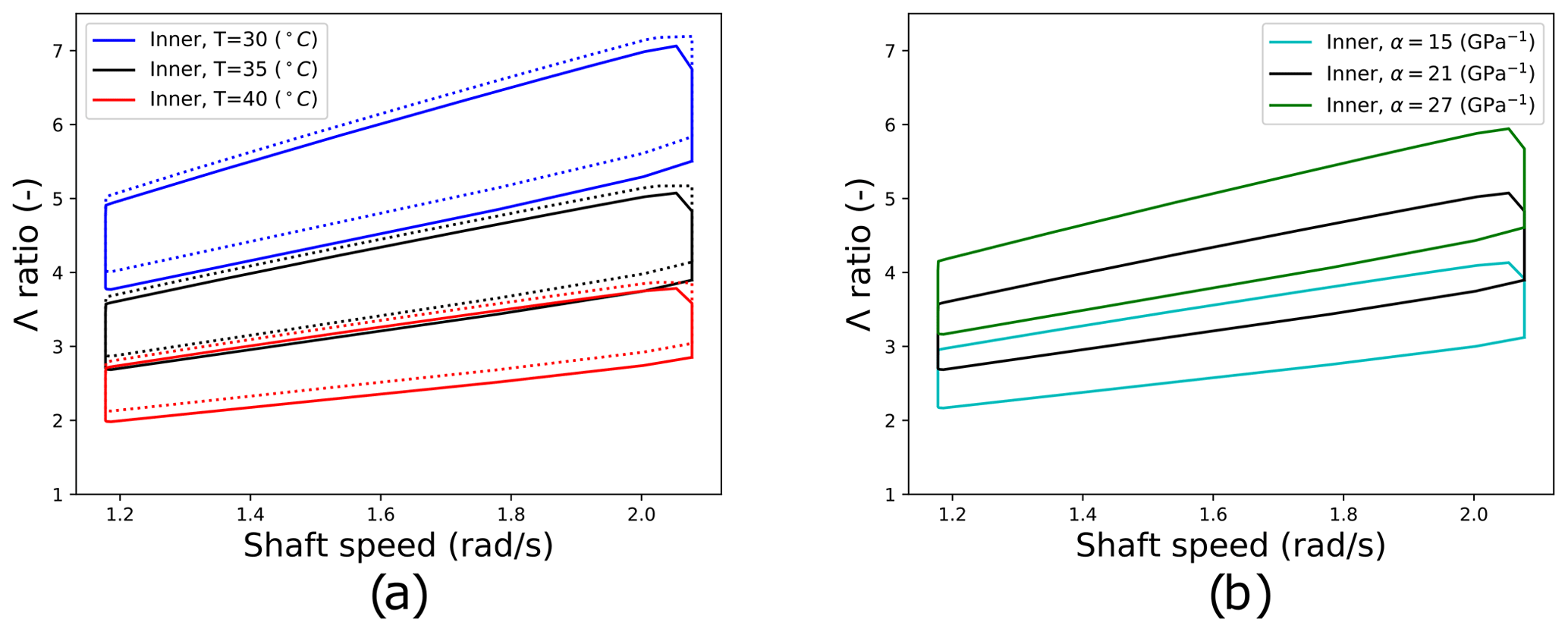
Figure D1Graphical results for sensitivity analyses on load and α* values. Panel (a) shows original results as solid lines, along with results obtained after all roller load values are halved (dotted lines). All three temperatures levels are included. Panel (b) shows the standard case, along with results obtained when α* is increased and decreased by 6 GPa−1.
For access to the dataset generated and analysed in this paper, please contact the corresponding author.
This work was led by EH. Code development and dataset generation were undertaken by EH and EdM. All authors contributed to dataset analysis, generation of results, and writing and editing stages of this work.
The contact author has declared that none of the authors has any competing interests.
Publisher’s note: Copernicus Publications remains neutral with regard to jurisdictional claims in published maps and institutional affiliations.
This work forms part of the project AMBERS (Advancing Main-BEaRing Science for wind and tidal turbines). Edward Hart is funded by a Brunel Fellowship from the Royal Commission for the Exhibition of 1851. Elisha de Mello's PhD project is funded by the Powertrain Research Hub, co-funded by the Offshore Renewable Energy Catapult. The authors would like to acknowledge their help and support. Finally, the authors would like to thank the anonymous reviewers for their helpful comments and suggestions.
This research has been supported by the Royal Commission for the Exhibition of 1851 (Brunel Fellowship 2020 grant).
This paper was edited by Amir R. Nejad and reviewed by three anonymous referees.
ASTM: D341–20e1 Standard Practice for Viscosity-Temperature Equations and Charts for Liquid Petroleum or Hydrocarbon Products, Standard, ASTM International, West Conshohocken, PA, https://www.astm.org/d0341-20e01.html (last access: 14 July 2022), 2020. a
Bair, S.: Shear thinning correction for rolling/sliding elastohydrodynamic film thickness, P. I. Mech. Eng. J-J. Eng., 219, 69–74, 2005. a
Beretta, M., Julian, A., Sepulveda, J., Cusidó, J., and Porro, O.: An Ensemble Learning Solution for Predictive Maintenance of Wind Turbines Main Bearing, Sensors, 21, 1512, https://doi.org/10.3390/s21041512, 2021. a
Bergua Archeli, R., Keller, J., Bankestrom, O., Dunn, M., Guo, Y., Key, A., and Young, E.: Up-Tower Investigation of Main Bearing Cage Slip and Loads, National Renewable Energy Lab (NREL), Golden, CO, USA, Tech. rep., https://www.nrel.gov/docs/fy22osti/81240.pdf (last access: 14 July 2022), 2021. a, b
Cardaun, M., Roscher, B., Schelenz, R., and Jacobs, G.: Analysis of Wind-Turbine Main Bearing Loads Due to Constant Yaw Misalignments over a 20 Years Timespan, Energies 2019, 12, 1768, https://doi.org/10.3390/en12091768, 2019. a
Cen, H. and Lugt, P.: Film thickness in a grease lubricated ball bearing, Tribol. Int., 134, 26–35, 2019. a
Cen, H. and Lugt, P.: Replenishment of the EHL contacts in a grease lubricated ball bearing, Tribol. Int., 146, 106064, https://doi.org/10.1016/j.triboint.2019.106064, 2020. a
Cen, H., Lugt, P., and Morales-Espejel, G.: Film thickness of mechanically worked lubricating grease at very low speeds, Tribol. T., 57, 1066–1071, 2014. a, b
Crook, A.: The lubrication of rollers III. A thermal discussion of friction and the temperatures in the oil film, Philos. T. Roy. Soc. A, 254, 237–258, 1961. a
Damiens, B.: Modélisation de la lubrification sous-alimentée dans les contacts elastohydrodynamiques elliptiques, PhD thesis, INSA, Lyon, 2003 (in French). a
de Mello, E., Kampolis, G., Hart, E., Hickey, D., Dinwoodie, I., Carroll, J., Dwyer-Joyce, R., and Boateng, A.: Data driven case study of a wind turbine main-bearing failure, J. Phys. Conf. Ser., accepted, 2022. a, b
Guo, Y., Bankestrom, O., Bergua, R., Keller, J., and Dunn, M.: Investigation of main bearing operating conditions in a three-Point mount wind turbine drivetrain, Forsch. Ingenieurwes., 85, 405–415, 2021. a, b, c, d, e
Hamrock, B., Schmid, B., and Jacobson, B.: Fundamentals of fluid film lubrication, 2nd edn., Mechanical Engineering, 169, CRC press, ISBN 0-8247-5371-2, 2004. a
Hart, E.: Developing a systematic approach to the analysis of time-varying main bearing loads for wind turbines, Wind Energy, 23, 2150–2165, 2020. a, b, c, d, e, f, g, h, i, j, k, l, m, n, o, p
Hart, E., Turnbull, A., Feuchtwang, J., McMillan, D., Golysheva, E., and Elliott, R.: Wind turbine main-bearing loading and wind field characteristics, Wind Energy, 22, 1534–1547, https://doi.org/10.1002/we.2386, 2019. a, b, c, d, e, f
Hart, E., Clarke, B., Nicholas, G., Kazemi Amiri, A., Stirling, J., Carroll, J., Dwyer-Joyce, R., McDonald, A., and Long, H.: A review of wind turbine main bearings: design, operation, modelling, damage mechanisms and fault detection, Wind Energ. Sci., 5, 105–124, https://doi.org/10.5194/wes-5-105-2020, 2020. a, b, c, d, e
Hart, E., de Mello, E., and Dwyer-Joyce, R.: Wind turbine main-bearing lubrication – Part 1: An introductory review of elastohydrodynamic lubrication theory, Wind Energ. Sci., 7, 1021–1042, https://doi.org/10.5194/wes-7-1021-2022, 2022. a, b, c, d, e, f, g, h, i, j, k, l, m, n, o, p, q, r, s, t, u, v, w, x, y, z, aa, ab, ac, ad, ae, af, ag, ah, ai, aj, ak, al, am, an
Hooke, C.: Dynamic effects in EHL contacts, in: Tribology Series, vol. 41, edited by: Dowson, D., Priest, M., Dalmaz, G., and Lubrecht, A. A., Elsevier, 69–78, https://doi.org/10.1016/S0167-8922(03)80120-7, 2003. a, b
IEC: Wind energy generation systems – Part 1: Design requirements, International Electrotechnical Commission, Tech. rep. 61400-1, 2019. a
ISO: Rolling bearings – Dynamic load ratings and rating life, International Organization for Standardization, Tech. rep. 281:2007, 2007. a, b
Kanazawa, Y., Sayles, R., and Kadiric, A.: Film formation and friction in grease lubricated rolling-sliding non-conformal contacts, Tribol. Int., 109, 505–518, 2017. a, b
Kock, S., Jacobs, G., and Bosse, D.: Determination of Wind Turbine Main Bearing Load Distribution, J. Phys. Conf. Ser., 1222, 012030, https://doi.org/10.1088/1742-6596/1222/1/012030, 2019. a, b, c
Loriemi, A., Jacobs, G., Reisch, S., Bosse, D., and Schröder, T.: Experimental and simulation-based analysis of asymmetrical spherical roller bearings as main bearings for wind turbines, Forsch. Ingenieurwes., 85, 189–197, 2021. a, b
Lugt, P. M.: Grease lubrication in rolling bearings, John Wiley & Sons, ISBN 978-1-118-35391-2, 2013. a
Masjedi, M. and Khonsari, M.: Film thickness and asperity load formulas for line-contact elastohydrodynamic lubrication with provision for surface roughness, J. Tribol., 134, 011503, 2012. a
Masjedi, M. and Khonsari, M.: A study on the effect of starvation in mixed elastohydrodynamic lubrication, Tribol. Int., 85, 26–36, 2015. a
Morales-Espejel, G. E., Lugt, P. M., Pasaribu, H., and Cen, H.: Film thickness in grease lubricated slow rotating rolling bearings, Tribol. Int., 74, 7–19, 2014. a, b
Nejad, A. R., Keller, J., Guo, Y., Sheng, S., Polinder, H., Watson, S., Dong, J., Qin, Z., Ebrahimi, A., Schelenz, R., Gutiérrez Guzmán, F., Cornel, D., Golafshan, R., Jacobs, G., Blockmans, B., Bosmans, J., Pluymers, B., Carroll, J., Koukoura, S., Hart, E., McDonald, A., Natarajan, A., Torsvik, J., Moghadam, F. K., Daems, P.-J., Verstraeten, T., Peeters, C., and Helsen, J.: Wind turbine drivetrains: state-of-the-art technologies and future development trends, Wind Energ. Sci., 7, 387–411, https://doi.org/10.5194/wes-7-387-2022, 2022. a, b
Ren, Z., Verma, A. S., Li, Y., Teuwen, J. J., and Jiang, Z.: Offshore wind turbine operations and maintenance: A state-of-the-art review, Renew. Sust. Energ. Rev., 144, 110886, https://doi.org/10.1016/j.rser.2021.110886, 2021. a
Rolink, A., Schröder, T., Jacobs, G., Bosse, D., Hölzl, J., and Bergmann, P.: Feasibility study for the use of hydrodynamic plain bearings with balancing support characteristics as main bearing in wind turbines, J. Phys. Conf. Ser., 1618, 052002, https://doi.org/10.1088/1742-6596/1618/5/052002, 2020. a, b
Stirling, J., Hart, E., and Kazemi Amiri, A.: Constructing fast and representative analytical models of wind turbine main bearings, Wind Energ. Sci., 6, 15–31, https://doi.org/10.5194/wes-6-15-2021, 2021. a, b, c
Vergne, P. and Bair, S.: Classical EHL versus quantitative EHL: a perspective part I—real viscosity-pressure dependence and the viscosity-pressure coefficient for predicting film thickness, Tribol. Lett., 54, 1–12, 2014. a, b
Wang, S., Nejad, A. R., Bachynski, E. E., and Moan, T.: Effects of bedplate flexibility on drivetrain dynamics: Case study of a 10 MW spar type floating wind turbine, Renew. Energ., 161, 808–824, https://doi.org/10.1016/j.renene.2020.07.148, 2020. a
Wheeler, J., Fillot, N., Vergne, P., Philippon, D., and Morales-Espejel, G.: On the crucial role of ellipticity on elastohydrodynamic film thickness and friction, P. I. Mech. Eng. J-J. Eng., 230, 1503–1515, 2016. a
Zheng, J., Ji, J., Yin, S., and Tong, V.-C.: Internal loads and contact pressure distributions on the main shaft bearing in a modern gearless wind turbine, Tribol. Int., 141, 105960, 2020a. a
Zheng, J., Ji, J., Yin, S., and Tong, V.-C.: Fatigue life analysis of double-row tapered roller bearing in a modern wind turbine under oscillating external load and speed, P. I. Mech. Eng. C-J. Mec., 234, 3116–3130, 2020b. a
Numbers reported in the literature indicate main-bearing failure rates can be as high as 30 % over a 20-year wind farm lifetime (Hart et al., 2019).
Instead, axial velocities of individual bearing rollers were estimated from measurements and compared to the mean entrainment velocity, . Literature results on axial velocity influences were then leveraged in order to conclude that the observed axial motions would not be expected to disturb the lubricant film.
This is only due to wl→0 here. It is emphasised that, in general, EHL films are relatively insensitive to the applied load, compared to other parameters (Hart et al., 2022).
Ry≈14 m at both inner- and outer-raceway contacts for this main bearing. Higher Rx and Ry values indicate that a larger surface area will be actively engaged in supporting applied loads.
There is some level of overlap between the lubrication regime designations relating to given ranges in Λ (Hamrock et al., 2004; Hart et al., 2022). For the sake of simplicity, in the current analysis the standard ranges have been interpreted in their most optimistic light. Therefore, the elastohydrodynamic regime is taken to be (with hydrodynamic lubrication assumed to take place for Λ>5), and the mixed regime is taken as . Boundary lubrication occurs for Λ<1.
In Morales-Espejel et al. (2014), a single tested grease does show higher transition film thickness values of around 300–700 nm. However, this was for a grease thickened using complex calcium sulfonate, whereas the grease considered in this study has a lithium complex thickener. The values associated with that particular grease were therefore discounted when identifying an appropriate transition thickness range in the present work.
For reasons of aerodynamic efficiency.
- Abstract
- Introduction
- Background
- Methodology
- Results
- Discussion and conclusions
- Appendix A: Table of symbols
- Appendix B: Entrainment velocity under pure rolling
- Appendix C: The validity of modelling approximations
- Appendix D: Lubrication results sensitivities
- Data availability
- Author contributions
- Competing interests
- Disclaimer
- Acknowledgements
- Financial support
- Review statement
- References