the Creative Commons Attribution 4.0 License.
the Creative Commons Attribution 4.0 License.
 | 05 Dec 2023
Electrostatic discharge impacts on the main shaft bearings of wind turbines
Jian Zhao
Xiangdong Xu
Ola Carlson
This paper studies the electrostatic discharge effect in wind turbines, a possible trigger source of the main bearing current. A lab setup with a charge generator and downsized wind turbine was built to verify the impact of electrostatic discharge on the main bearing current. In the test, a fatal amplitude for the bearing current was found at only −93 mV driven voltage on the shaft. Compared with the bearing current driven by the common-mode voltage, the electrostatic discharge effect triggers the bearing breakdown at a lower shaft voltage but much higher bearing current amplitude. The results demonstrate that the electrostatic discharge effect is a pattern of the bearing current in wind turbines and is much more dangerous to the bearing.
- Article
(5121 KB) - Full-text XML
- BibTeX
- EndNote


As economic development advances, more and more electrical power is demanded in day-to-day life and industrial production. However, traditional power generation methods are not usually environmentally friendly. Due to its renewability and almost zero CO2 emissions, wind power is deemed a promising future power source.
Wind turbines only require an initial investment for construction, and their maintenance costs are usually extremely low compared to the investment. However, replacing core components in the nacelle (located at the top of the tower) is extremely expensive. Of the core components, replacing the main shaft bearing (which holds the rotor weight and protects the shaft from the wind axial force) is very complicated and costly.
The main shaft bearing can break down for various reasons, such as poor fitting, poor lubrication, installation, material defects, excessive mechanical load and electrical current erosion (Radu, 2010; Gemeinder and Weicker, 2021). Different failure patterns often trigger each other, with the bearing ultimately breaking down completely. One of the other failure patterns is bearing current erosion (Muetze, 2004; Muetze and Binder, 2005). This develops very slowly, making it difficult to know that a wind turbine's main bearing is eroding. Furthermore, although bearing current erosion will not burn out a bearing quickly, it will worsen its operating state and trigger other bearing failure patterns.
The bearing failure mechanism under an electrical current has been studied by different researchers (Muetze and Binder, 2007; Binder and Muetze, 2008; Radu, 2010). However, most studies have focused on the bearing inside electrical machines, with very little attention paid to the main shaft bearing current erosion. The electrical erosion process in a bearing is similar to that of a bearing current inside an electrical machine, but its origins differ greatly. Studies of bearing current sources in wind turbine main bearings mainly deal with the impact of common-mode voltage (Haitham et al., 2014; Weicker, 2021).
The electrostatic discharge effect has been widely studied in the high-voltage field (Mainra et al., 2022; Prashad, 2006) but its impact on a wind turbine's main shaft bearing has gone unnoticed by industry and academia. This paper analyses and investigates the electrostatic discharge effect on the main shaft bearing current. Its generation, transmission path and impact on the main shaft bearing are studied and discussed in different sections. Various groups of tests were run in a laboratory setting to verify their impact on the main shaft bearing.
In nature, wind is produced by air movement arising from local temperature differences. Air contains a great many particles such as dust, water drops, ice and so on. When wind arises, these particles move with it and collide with each other. On a microscopic level, the molecules of the various particles can exchange electrons when they collide due to differences in their electron affinity. Thus, a large number of free charges are generated and accumulated in the clouds, contributing to atmospheric phenomena such as thunderstorms and lightning. When heavily charged clouds form on top of a wind turbine with a sharp blade tip, charges of opposite polarity, with respect to the clouds' charges, can be easily induced in the wind blades from the ground via the turbine's lightning protection system.
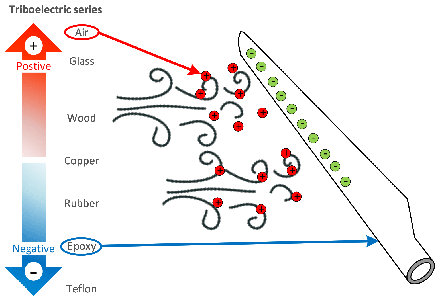
Additionally, the blades can be electrically charged when wind comes into contact with the blades and is separated. This effect is known as triboelectric charging. As shown in Fig. 1, different materials' electron affinities are shown. Air is likely to given out electrons, and polymers, such as epoxy and PTFE, have the ability to attract electrons and become negatively charged.
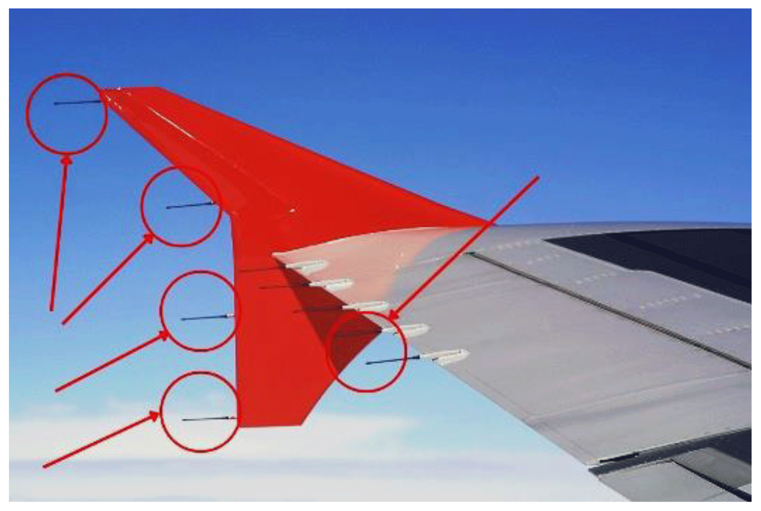
One example of minimizing the triboelectric effect in engineering applications is the static dischargers on aeroplanes. An aeroplane's surface is often coated with polyurethane. As the plane moves in the air, its surface will accumulate charges and induce a high electric field, causing uncontrolled discharges and damaging the aeroplane parts, especially modern electronics. To avoid such discharge risk, a number of needle-shaped dischargers are installed on the wings, as shown in Fig. 2; these needles provide discharge points to dissipate accumulated charges back to the air via so-called corona discharges.
The accumulated charge on the wind turbine blades' polymeric dielectric surfaces builds up an electric potential and attempts to find its way to ground for dissipating the accumulated charge.
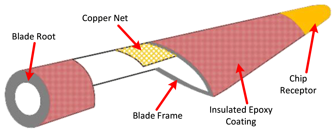
The structure of a typical wind turbine is shown in Fig. 3. The blade has a multilayer structure, consisting of the blade frame, filling material, lightning protection components and surface coating. The frame, which provides the basic mechanical structure, is usually made of wood, glass fibre or carbon fibre. The outermost surface of the frame is coated with a layer of epoxy-resin-based polymeric coating to prevent erosion. Inside the blade, the lightning protection system comprises receptors and a copper net. The receptors that attract lightning from clouds are installed at the tip and middle of the blade respectively (Méndez et al., 2018) and are located on the outermost part of the coating. The copper net that provides a path to ground is embedded between the epoxy coating and the frame.
Regarding the blade structure, most components are dielectric materials, except for the lightning protection components. This provides a path for the surface-accumulated charges to be naturalized.
At the wind turbine level, the continuously accumulated charges on the blades find a way to discharge to the wind turbine's lightning protection system and conduct to the ground (Hernández et al., 2019), resulting in a current flow. There are different types of wind turbines configurations, with the most widely installed ones being geared and gearless turbines. Figure 4 shows a typical wind turbine with gearbox transmission, the main bearing and the gearbox installed directly on the main shaft. The generator is connected to the gearbox via an insulated coupling. In gearless wind turbines, the gearbox is eliminated, and the generator is installed directly with the main shaft.
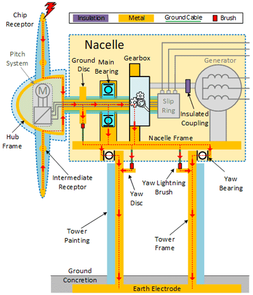
In the lightning protection system, the blades are electrically connected to the hub frame and main shaft. The main shaft is fitted with a carbon brush which conducts charges on the main shaft to the nacelle frame and onward to the grounding system via the tower frame.
However, in reality, charges may take different paths from the main shaft to the nacelle frame. Though the main shaft has a brush installed, there is also the main bearing and gearbox (geared turbine) or generator (gearless turbine). The main bearing and gearbox bearing or generator bearing provide a parallel current path for charges on the main shaft. The different paths are indicated by dashed red lines with arrows in Fig. 4.
If the electric current continuously goes through the bearing, the lubrication grease will be prematurely aged, and the races may get damaged. In the main shaft's ground path, the resistance of each component determines the amount of current on each parallel path.
Figure 5 shows a typical ground brush and a main shaft bearing. The ground brush is a cuboid block around 5 cm long and 1 cm wide, usually made of carbon or metal with one of the cambered surfaces to match the surface of the ground disc. The main bearing is a double-row tapered roller bearing, comprising an inner race, outer race, rollers and lubrication grease. Its diameter ranges from a few dozen centimetres to metres. Thus, contact surfaces area of a main shaft bearing can be significantly larger than the contact surface of a ground brush, resulting in a lower-resistance path for charges to flow.
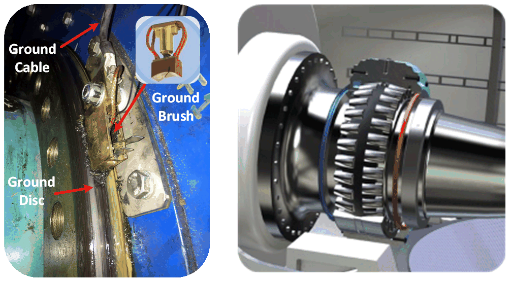
Figure 6 shows a typical roller bearing structure. It consists of an inner ring, outer ring, rollers and roller cage, plus oil or grease packed between the races and rollers. In the turbine, the inner race's electrical contact is a mechanical connection to the main shaft, while the outer race is connected to ground via the bearing housing.
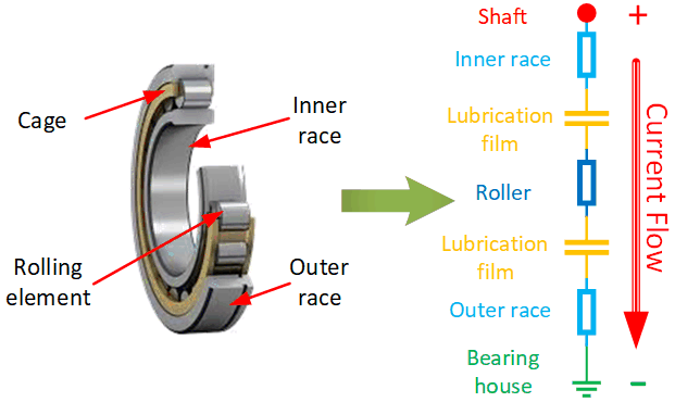
The inner race, outer race, rollers and cage are made of metal. The rollers are held by the cage and are thus electrically connected. From the electric circuit standpoint, the bearing can be modelled as a capacitor and a resistor in series. Compared with the impedance of the capacitor, the resistance value is extremely small and usually disregarded in the circuit model.
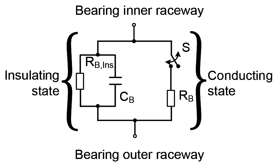
The electrical properties of bearings have been studied by many researchers. In the rotation system, the bearing has different electrical states at different rotation speeds. At low rotation speeds, the main bearing supports the rotor, which weighs several tonnes. The lubrication grease between the roller and races is only partially filled, and the bearing operates in a conductive state. As the rotation speed of the rotor increases, a thin gap between the roller and races is formed and may be filled with the lubrication grease; thus the bearing switches to its insulated state. A typical electrical model (Joshi, 2018) of the bearing is shown in Fig. 7. In this model, a switch is used to model the state transition of the bearing.
5.1 Electrostatic charges vs. charge generation sources
Electrical charge flows around in the open air, and there are always opportunities for it to become attached to wind turbine blades. Due to the large size of wind turbines, the accumulated charge will generate a non-negligible electric potential on the main shaft. This electric potential tries to be neutralized to ground via a path of least resistance.
The phenomenon elaborated above needs to be verified and studied with simplified conductive paths in a wind turbine; a downsized lab setup has therefore been constructed. Furthermore, due to the turbine's smaller size, the charge accumulated on the lab-scale wind turbine blades is not sufficient to generate a sensible current flow and damage to the main bearing. So, an external discharge source is utilized to increase the charge density in the air.
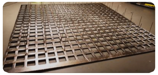
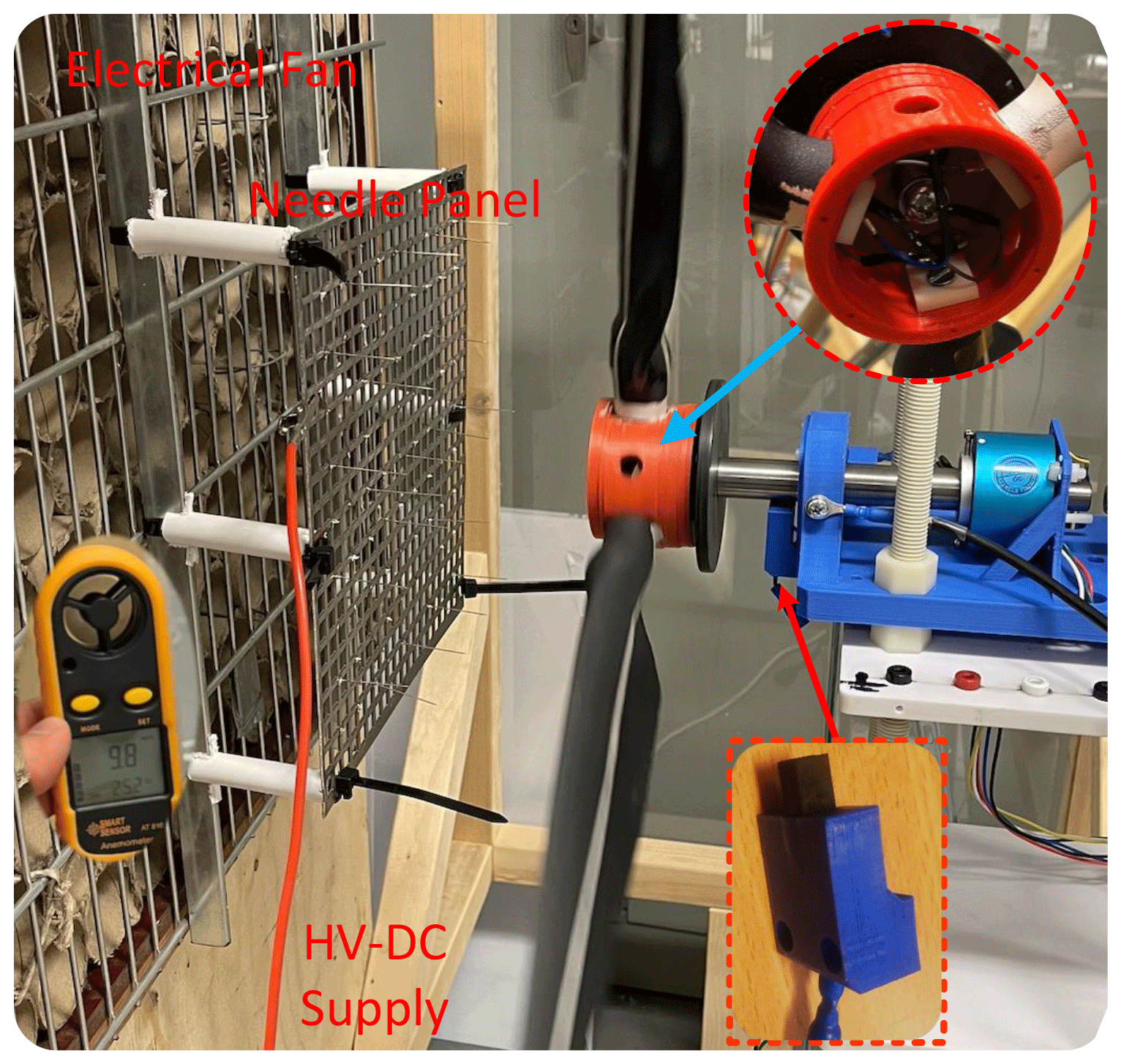
To increase the charge density, a needle panel is used to release charge to the air by means of corona discharges. As shown in Fig. 8, the needle panel is made of a steel net with a number of needles welded onto it and connected to an adjustable negative high-voltage direct current (HV-DC) source. The panel is mounted in front of an electrical fan which provides a controllable airflow across the needle panel, brings charges into a wind tunnel and increases the charge density inside.
5.2 Simplified wind turbine configuration
The basic structure of the wind turbine's lightning protection system is introduced in Sect. 3. In a real wind turbine, different subsystems are mounted inside the nacelle, and their layout differs greatly from turbine to turbine. In this study, the main point of interest is the current in the main shaft bearing. Therefore, in the lab setup, the wind turbine configuration should be simplified to highlight the charge-dissipating path and redundant subsystems are removed.
In a geared wind turbine, the gearbox is mechanically connected to the main shaft and to the generator via an insulated coupling. Thus, the generator has no direct electrical contact with the main shaft. The main shaft voltage is dissipated via the ground brush, main bearing and gearbox bearing.
In a gearless wind turbine, the main bearing is mounted between the main shaft and generator frame. The possible dissipation paths for the main shaft voltage are the ground brush and the main bearing.
In one of the different types of gearless turbines, the main shaft is directly connected to the generator. The configuration is similar to that of the geared wind turbine. The main shaft is grounded via the ground brush, main bearing and generator bearing.
To summarize the different transmission arrangements, the common grounding paths are the ground brush and main bearing. In this study, the main topic of interest is the impact of electrostatic discharge on the main shaft bearing. Thus, the lab setup only considers these two common paths. Figure 9 shows the simplified wind turbine configuration. It includes the charge generation subsystem, lightning conducting subsystem, ground brush and main bearing of the turbine suspension system.
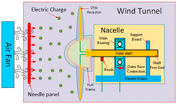
Figure 9Illustration of the simplified wind turbine configuration utilized in the lab study.
5.3 Experimental setup
The downsized turbine part indicated in Fig. 9 is located inside the wind tunnel, which is made of wood and plastic sheeting. Its centre height is 1 m with a diameter of 75 cm. Most components in the downsized turbine are made of non-conductive plastic. This includes the rotor hub and blades, rotor suspension subsystem, lightning protection subsystem, and turbine frame.
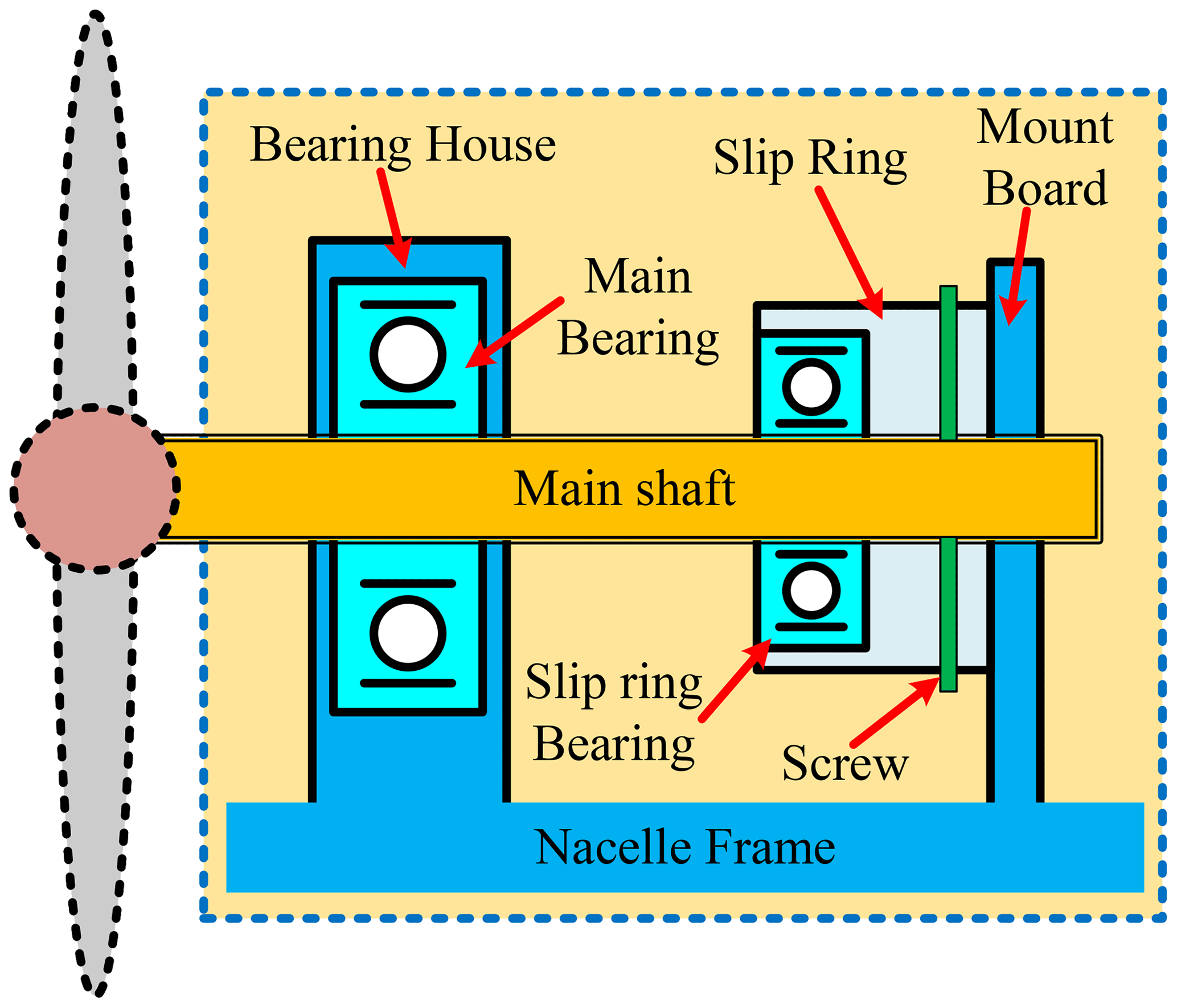
The suspension subsystem supports the turbine rotor and locks the rotor, preventing it from axial movement. Its principal components are the main bearings, nacelle frame and slip ring. Its configuration is shown in Fig. 10. The suspension consists of a two-point system whose rotor is suspended by two bearings. The main bearing inside the bearing housing is a typical cylindrical roller bearing (SKF NU 204) that can only support a radial load, while the slip ring bearing inside the slip ring is a typical ball bearing that can support both radial and axial loads. The nacelle frame, bearing housing and mounting board are manufactured as a single unit. The slip ring is mounted on the mounting board, thus locking the slip ring in the axial direction. The main shaft goes through the main bearing and slip ring. At the rear end of the slip ring, the main shaft is locked together with the slip ring by screws. Thus, the rotor is locked in the axial direction by the slip ring and mounting board.
In the simplified setup, the lightning protection subsystem comprises coated plastic blades, plus the hub connection, main shaft and ground brush.
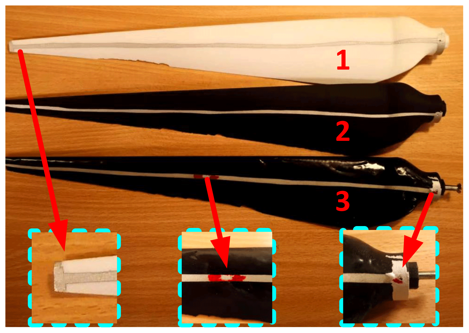
Figure 11 shows the coated blades. These are 3D-printed in different colours of nylon. Electrically conductive silver lines are painted on both sides of the blades to provide the conductive path. Rectangular areas are painted onto the blade tips to simulate the chip receptors. A screw mounted at the root of each blade electrically connects to the silver-painted lines via a copper wire. The whole surface of blade 3 in Fig. 11 has been coated with a layer of epoxy resin, except for the tip and a pit in the middle as lightning receptors.
The main shaft is hollow steel, with the hub mounted on the output side by a nut. Inside the hub, the screws into the blade's root are electrically connected to the shaft's rear end by three cables. These details are also illustrated in Fig. 9. On the shaft's drive side (see bottom inset in Fig. 12), a carbon brush holder is mounted on the nacelle board, and the carbon brush is forced into contact with the surface of the main shaft by a spring. A conductive cable at the end of the brush connects the brush to the system's ground or test equipment.
To verify that the electrostatic discharge effect does impact the main shaft bearing, various groups of tests were designed for the downsized wind turbine lab system.
6.1 Lab test conditions and bearing connection
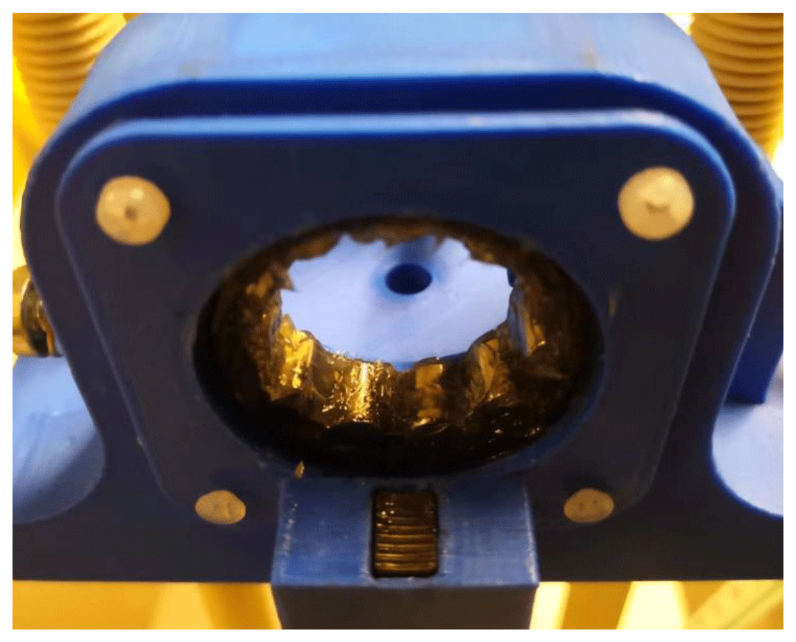
According to the electrical model of the bearing introduced in Sect. 4, the bearing operates in the conductive state under low-speed rotation but switches to its insulated state as the speed increases. In a wind turbine, the main bearing normally operates in its insulated state. Under lab conditions, the selected bearing uses an thin oil-based lubrication in the cylindrical roller and thus often operates in its conductive state. To keep the lab working state of the turbine main bearing similar to the main shaft bearing in wind turbines, thicker grease-based lubrication was injected into the space between the rollers and races. The bearing with extra non-conductive grease is shown in Fig. 13.
To keep the test repeatable, a basic test condition was set for all tests in this study. On the charge generation side, the wind speed was kept at a stable value (5–6 m s−1) and the voltage level was adjusted to achieve different charge densities in the wind tunnel. The turbine was driven by the wind at around 80 rpm, and there was no load connected to the main shaft (in other words, the generator was disconnected from the shaft). The distance between the needle panel and turbine hub was fixed at 30 cm to limit the charge travel distance.
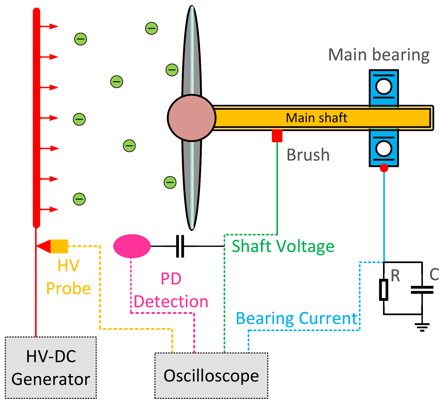
Compared to the field wind turbine, the brush used in the lab setup is served as a voltage probe and connected to the ground via the oscilloscope's 1 MΩ input impedance. To emulate a similar current path in the real wind turbine, the miniature bearing with a dynamic impedance of 10 kΩ is selected by scaling. As based on our field measurements, due to lubrication and contaminations, the brush's dynamic contact resistance is generally high, over 10 kΩ, whereas the bearings' impedances are in the range of a few ohms; thus the current will mainly pass through the bearing instead of the brushes. In the lab setup, the miniature bearing's outer ring is grounded via a current shunt. Connected in this way, the current will mainly pass through the bearing. Figure 14 shows the test connection for the setup.
One may notice the use of a coupling capacitor in the partial discharge (PD) detection circuit. This in principle will influence the discharge intensity; nevertheless, based on our tests, we do not observe any significant difference in results with and without the PD detection circuit. This is likely due to the incoming charges stored on the blades being strong enough to cause frequent discharges.
Inside the bearing, the charge will accumulate at the roller and generate an unevenly distributed electric field within an insulated bearing. Once the electric field strength is greater than the withstand strength of the lubrication grease at the bearing, an electric discharge will occur. A strong current will flow through grease and be conducted to ground via the outer ring and ground cable.
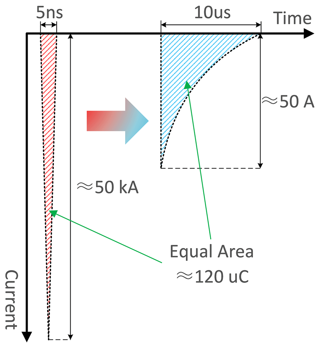
The discharge has an extremely high amplitude current flowing for an extremely brief period. This is usually a matter of a few nanoseconds with the current amplitude being in the kiloampere range. The amplitude and bandwidth of the discharge current are usually beyond the measurement range of an oscilloscope. To capture the current, the main bearing is grounded via a parallel resistor and capacitor (RC) circuit which measures the bearing discharge current. In this RC circuit, the capacitor slows the current flow, and the shunt resistor converts the current signal into a voltage signal. As shown in Fig. 15, the RC circuit slows the progress of the discharge current and reduces its amplitude. But the total quantity of dissipating charges remains the same.
In the test setup, the shunt capacitor used is 100 pF and the shunt resistor is 1 kΩ. In the test connection shown in Fig. 14, one side of the current shunt is connected to ground and the other feeds into the oscilloscope, which measures the current passing through the main bearing as a voltage signal.
The input voltage on the needle panel is measured by the oscilloscope via a high-voltage probe. A high-pass filter is connected to the shaft voltage signal and extracts the high-frequency discharge signal from it.
6.2 Induced shaft voltage due to charge accumulation
In the setup, different parameters influence the charge density in the wind tunnel. The main purpose of this study is to determine the charge's impact on the main bearing. Thus, the voltage applied to the discharge needles in the test is varied to adjust the charge density generated in the tunnel.
6.2.1 Test A – bearing state measurement
Due to the extra grease injected into the main bearing, the bearing can operate in its insulated state. The first test verifies the bearing's operating state. Figure 16 shows the test connection; a 2.5 V square wave voltage signal with a frequency of 1 kHz is applied to the shaft via the carbon brush, and the main bearing's outer race is connected directly to the oscilloscope to monitor its voltage.
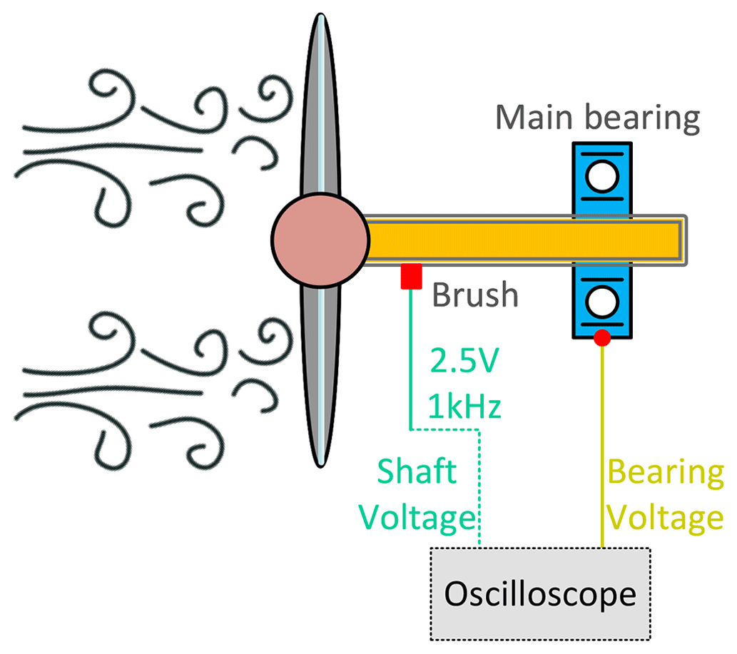
The turbine was rotated by the wind (5–6 m s−1) at around 80 rpm, and there was no charge generation from the needle panel. The bearing, with and without grease, is shown in Figs. 17 and 18 respectively.
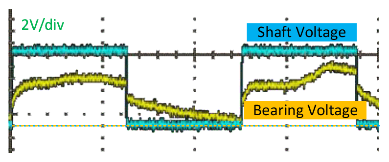
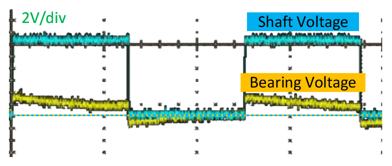
In the case of the bearing without grease, the bearing often operates in a conductive state, with the outer race voltage waveform nearly following the input voltage and showing very little voltage drop on the bearing impedance. In the case of the bearing with grease, there was a significant potential difference between the inner and outer races, indicates an insulating state in bearing.
It is clear that injecting grease into the main bearing changes its operating condition from a conductive state to an insulated one. Furthermore, under the insulation state, there was no electrical breakdown in the bearing at 2.5 V.
6.2.2 Test B – shaft-induced voltage
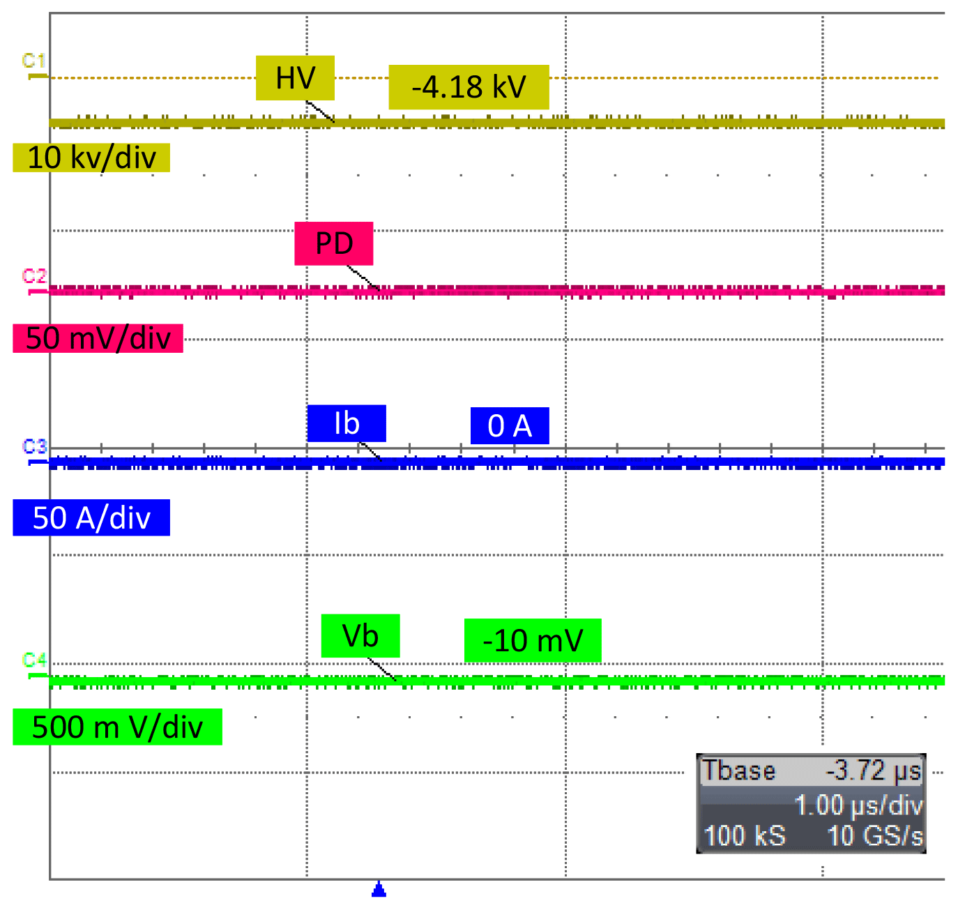
Using the test system connection in Fig. 14, different direct current (DC) voltage levels were applied to the needle panel. In the test, the charge that accumulated or was induced on the blade was conducted to the main shaft via the lightning protection system. The charges accumulated on the main shaft are impeded by the grease in the main bearing to the ground. The electrical properties of the main bearing mean that it acts as a dynamic capacitor, blocking DC but conducting alternating current (AC). The charges from the air are unipolar particles, whose movement generates a negative DC current flow from the blade to the main shaft. These airborne charges are stored on the bearing's inner race and build up a DC electric potential on the main shaft. As shown in Fig. 19, for the needle panel supplied with a voltage of −4 kV in channel 1 and in channel 4, a voltage of −10 mV is induced on the shaft. Because the airborne charges form negative sources, the voltage on the main shaft is also negative. Based on the bearing's current curve in channel 3, there is no current flowing through the bearing.
6.2.3 Test C – bearing breakdown
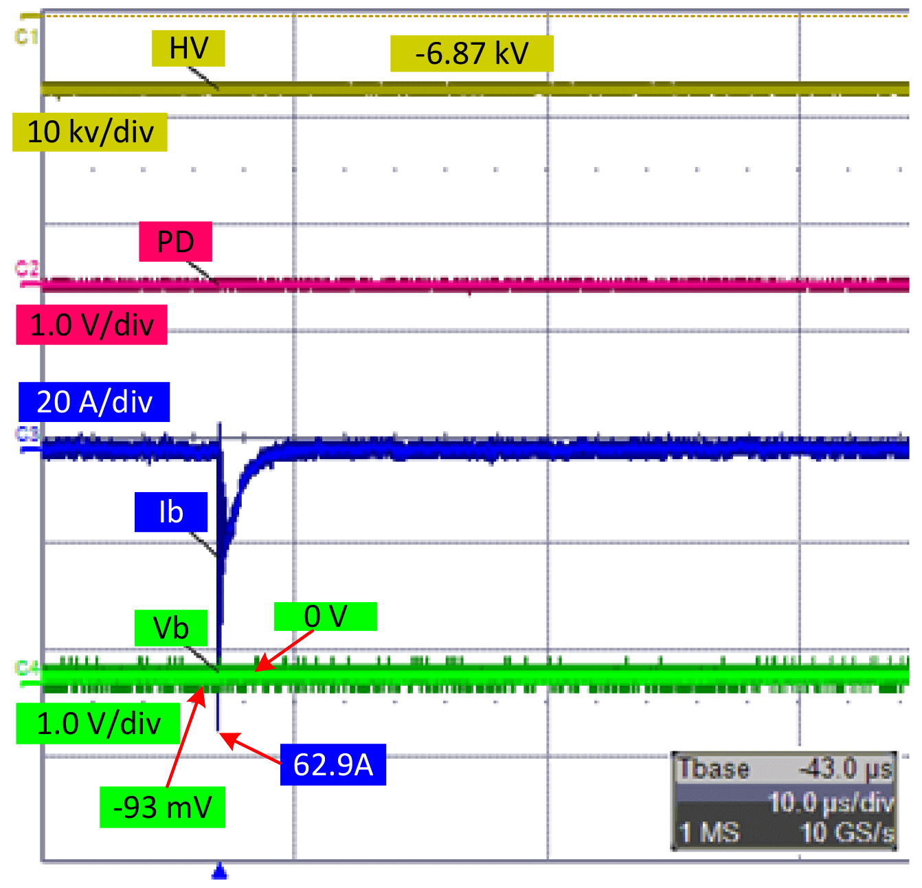
In Fig. 20, with a −6.87 kV DC voltage applied to the needle panel, the voltage build-up on the main shaft reached only −93 mV. From the bearing current curve, a breakdown clearly occurred on the bearing and its amplitude reached 62.9 A. During the breakdown process, the induced voltage on the shaft dipped to zero.
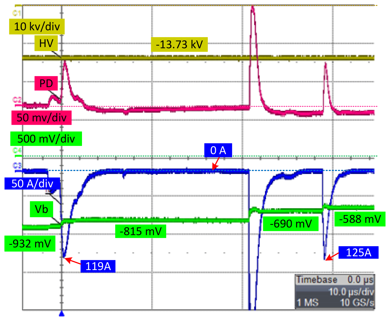
With the increasing needle voltage, the charge density in the tunnel further increases. When the needle voltage was increased to −14 kV, the bearing broke down more frequently. The test results appear in Fig. 21, in which the induced voltage reaches −932 mV. Within the same time span as Test B, breakdown occurred three times, with the bearing current amplitude reaching hundreds of amps. During each breakdown, the shaft voltage dipped by several hundred millivolts.
6.2.4 Test E – bearing conductive state change
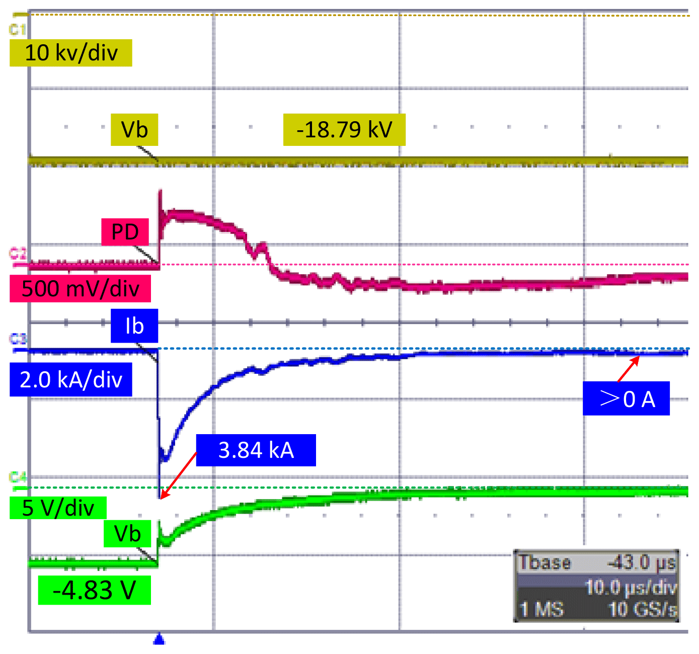
Further increasing the charge density, the applied needle voltage was adjusted to −18.79 kV. As indicated in Fig. 22, the induced shaft voltage reached −4.83 V. The breakdown occurred in the bearing during rotation, with the current flowing through the bearing peaking at 3.84 kA. After the breakdown, the bearing's operating state reverted to a conductive state. There was a continuous current flow through the bearing, even after the voltage had dropped to nearly zero.
In Test A, a 2.5 V 1 kHz AC voltage was applied to the bearing with grease lubrication, and no breakdowns or discharges were observed. Compared to the Tests C and D results, discharges occurred more frequently when the shaft voltage was less than 1 V, indicating discharges were largely related to charge accumulation at the bearing.
The bearing operated in its insulated state with the wind rotating the lab wind turbine. The grease thickness varies with rotation speed, the rollers' position and the load on the bearing, and, from an electrical point of view, the bearing may be modelled as a capacitor. The capacitance varies with the thickness, but generally, the capacitance stays within a stable range of dynamic values.
In Test A, a 1kHz AC voltage was applied to the shaft and the charges within the bearing capacitor were periodically polarized and depolarized. During each period, more charges did not have enough time to be accumulated and generate an electric field that was strong enough to break down the grease dielectric.
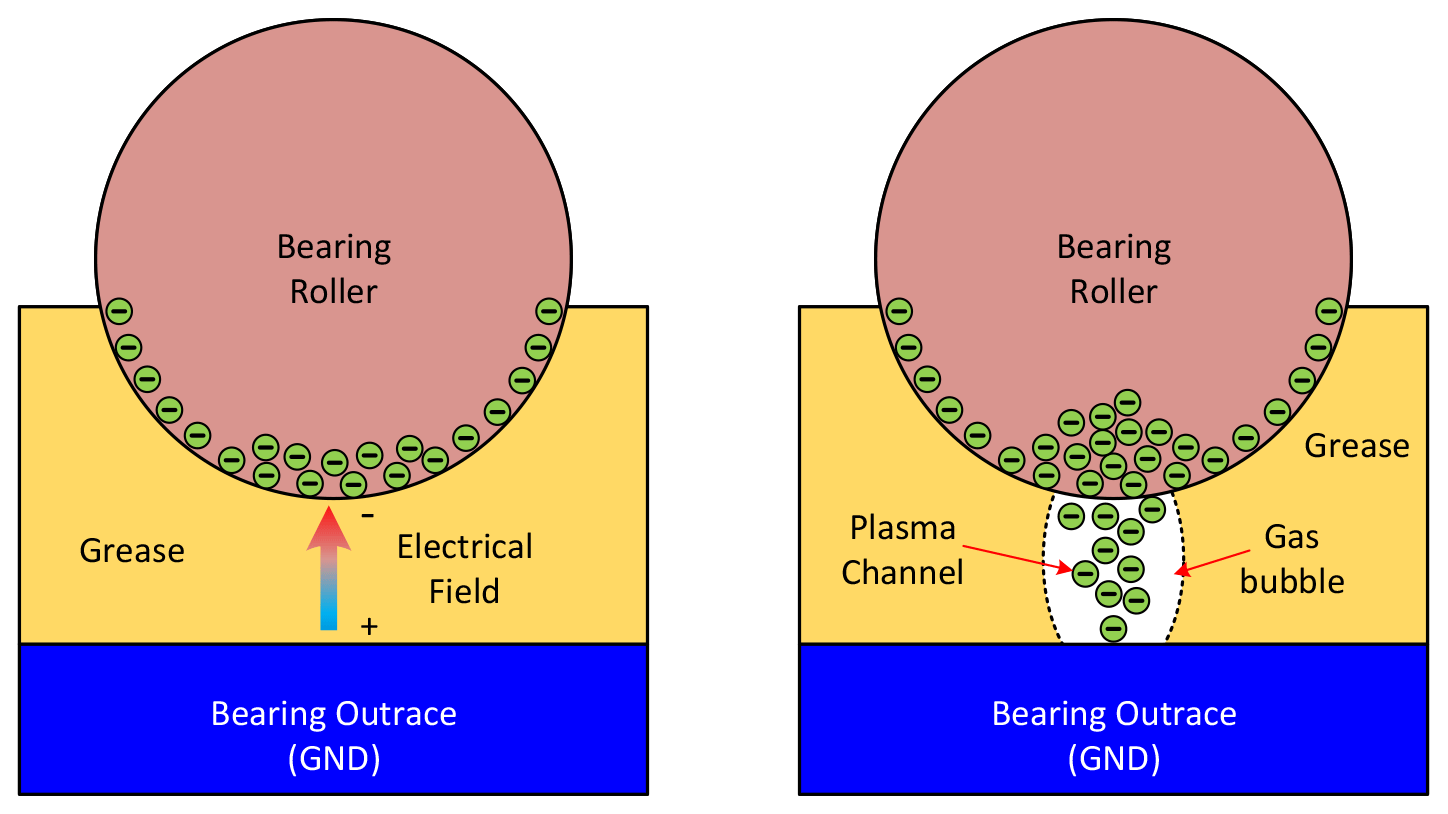
Unlike in Test A, in Test B, a DC potential was built up at the shaft by means of charge accumulation via the blades. As shown in Fig. 23 (left panel), the accumulated charges built up a static electric field over the grease. But the amplitude of the electric field on the bearing grease was not strong enough to break down the bearing. Thus, the potential on the main shaft kept at a stable DC value, as shown in Fig. 19.
In Test C and Test D, by increasing the voltage level to the needle panel, more charges were generated and travelled to the shaft via blades and, consequently, caused higher potentials at the shaft. With the rotation of the bearing, the grease thickness changed dynamically, and the electric field strength over the grease was inversely proportional to that thickness. In Test C, even though the shaft voltage was only −93 mV, the accumulated charges generated a local electric field strong enough to cause breakdowns in bearing when grease dynamically reached a small enough thickness during rotating.
In the AC-driven case in Test A, the accumulated charge on the bearing appears as a tidal waveform, which means the charges accumulated and dissipated periodically from the source. In the bearing current driven by electrostatic discharge (ESD), the voltage is a DC source and the charge build-up field is a continuously increasing field. Compared with Test A in Fig. 18, even though the voltage level in Test C (Fig. 20) is lower, the partial electrical field is stronger than the case of AC voltage in Test A.
During the bearing breakdown, the electric arc is generated through the grease and causes a gas channel between the roller and outer race. With increasing current flow, a plasma channel can be built (as shown in Fig. 23, right panel) and the accumulated charges are dissipated to the outer race, which is grounded via the mechanical connections. The shaft voltage dipped to zero, and the electric field on the bearing grease was not enough to maintain the discharge channel. Thus, the discharge channel disappeared with the rotation and the breakdown process ended (Maradia and Wegener, 2015).
In Test E, with increasing charge density in the air, the charges were continuously conducted to the shaft. Once the electric field on the bearing was strong enough, breakdown occurred in the bearing grease. After the breakdown, the charges dissipated to ground via the discharge channel. With subsequent charges from the blades, these charges maintained a continuous flow of current through the discharge channels inside the bearing grease. From the test results shown in Fig. 22, it is obvious that, after the breakdown, the shaft voltage gradually dropped to nearly zero, but the current was maintained at a stable value.
Comparing the test results from Tests C to E, the charge density increased gradually and the shaft voltage increased from −93 mV to −4.8 V. It became easier and easier to trigger a breakdown in the bearing. The amplitude of the bearing current began appearing from 63 A to 3.8 kA. According to Fig. 15, the current peak was suppressed by the shunt circuit. Assuming a constant discharge duration of 5 ns, the amplitude of the currents' peak can be calculated as 1.2, 60 and 210 kA in Tests C to E respectively.
This paper has studied and discussed the phenomenon of the wind turbine main shaft bearing current. The ESD effect in wind turbines is found to have a significant impact on the main shaft bearing's ageing. This paper has analysed its root cause and the transmission path of electric charges. Furthermore, to verify the analysis, a downsized wind turbine was built under lab conditions to simulate a field wind turbine. Several groups of tests were conducted on the lab turbine, with a fatal bearing current amplitude only found at a driven voltage of −93 mV (Muetze, 2004; Muetze and Binder, 2006; Muetze et al., 2006). Compared with the AC voltage-driven bearing current, the ESD-driven bearing current appears at a lower trigger voltage and higher discharge current amplitude. Furthermore, based on the charge movement in the test results, the breakdown mechanism of the ESD-driven bearing current was studied at a micro-perspective level of detail. The analysis and test results prove that the ESD effect is a non-negligible source of the main shaft bearing current in wind turbines and that it is feasible to reach fatal discharge currents in the bearing.
All raw data can be provided by the corresponding author upon request.
This work was launched by all the authors. JZ and XX planned and prepared the lab setup and did the lab test. The paper was written by all the authors: ZJ started the draft, and XX and OC provided useful comments and finalized the paper.
The contact author has declared that none of the authors has any competing interests.
Publisher's note: Copernicus Publications remains neutral with regard to jurisdictional claims made in the text, published maps, institutional affiliations, or any other geographical representation in this paper. While Copernicus Publications makes every effort to include appropriate place names, the final responsibility lies with the authors.
This study was carried out in the scope of the research project “Detecting and eliminating bearing currents for longer lifespan of main shaft bearings”. This project is launched together with SKF, Rabbalshede Kraft, Göteborg Energi AB, ABB AB and Skellefteå Kraft. The authors sincerely acknowledge their support.
This research has been supported by the Energimyndigheten (grant no. 2017-008071/44949-1).
This paper was edited by Amir R. Nejad and reviewed by two anonymous referees.
Binder, A. and Muetze, A.: Scaling Effects of Inverter-Induced Bearing Currents in AC Machines, IEEE T. Indust. Appl., 44, 769–776, https://doi.org/10.1109/TIA.2008.921378, 2008.
Gemeinder, Y. and Weicker, M.: Application Guide Bearing Currents_V2.3, Institut für Elektrische Energiewandlung, Technische Universität Darmstadt, Darmstadt, https://doi.org/10.26083/tuprints-00019393, 2021.
Haitham, A.-R., Mariusz, M., and Kamal, A.-H.: Common-Mode Voltage and Bearing Currents in PWM Inverters: Causes, Effects and Prevention, in: IEEE Power Electronics for Renewable Energy Systems, Transportation and Industrial Applications, Wiley, 664–694, https://doi.org/10.1002/9781118755525.ch21, 2014.
Hernández, Y. M., Madsen, S. F., Sorensen, T. S., Yasuda, Y., Birkl, J., Yokohama, S., Plumer, J. A., and Yamamoto, K.: An Insight on the IEC 61400-24 Ed2: Lightning Protection of Wind Turbines, in: 2019 International Symposium on Lightning Protection (XV SIPDA), 30 September–4 October 2019, Sao Paulo, Brazil, 1–6, https://doi.org/10.1109/SIPDA47030.2019.8951662, 2019.
Joshi, A.: Electrical Characterisations of Bearings, PhD thesis, Chalmers University of Technology, ISBN 978-91-7597-839-0, https://research.chalmers.se/publication/508930/file/508930_Fulltext.pdf (last access: 4 February 2019), 2018.
Mainra, J. K., Kaur, A., Sapra, G., and Gaur, P.: Simulation and Modelling of Triboelectric Nanogenerator for Self-powered Electronic Devices, IOP Conf. Ser.: Mater. Sci. Eng., 1225, 012012, https://doi.org/10.1088/1757-899x/1225/1/012012, 2022.
Maradia, U. and Wegener, K.: EDM Modelling and Simulation, Nova Science, 67–121, ISBN 978-1-63483-598-5, 2015.
Méndez, Y., Birkl, J., Madsen, S. F., Sørensen, T., Plumer, J. A., and Montanya, J.: The 2018 Revision of the Standard IEC 61400-24: Lightning Protection of Wind Turbines, in: 2018 34th International Conference on Lightning Protection (ICLP), 2–7 September 2018, Rezeszow, Poland, 1–6, https://doi.org/10.1109/ICLP.2018.8503411, 2018.
Muetze, A.: Bearing Currents in Inverter-Fed AC-Motors, TU Darmstadt, Darmstadt, https://api.semanticscholar.org/CorpusID:112828069 (last access: 20 November 2023), 2004.
Muetze, A. and Binder, A.: Generation of high-frequency common mode currents in machines of inverter-based drive systems, in: 2005 European Conference on Power Electronics and Applications, 11–14 September 2005, Dresden, Germany, 10 pp., https://doi.org/10.1109/EPE.2005.219489, 2005.
Muetze, A. and Binder, A.: Don't lose your bearings, IEEE Indust. Appl. Mag., 12, 22–31, https://doi.org/10.1109/MIA.2006.1678327, 2006.
Muetze, A. and Binder, A.: Practical Rules for Assessment of Inverter-Induced Bearing Currents in Inverter-Fed AC Motors up to 500 kW, IEEE T. Indust. Electron., 54, 1614–1622, https://doi.org/10.1109/TIE.2007.894698, 2007.
Muetze, A., Binder, A., Vogel, H., and Hering, J.: What can bearings bear?, IEEE Indust. Appl. Mag., 12, 57–64, https://doi.org/10.1109/IA-M.2006.248014, 2006.
Prashad, H.: Tribology in Electrical Environments, in: Tribology and Interface Engineering Series, Elsevier, 301–324, https://doi.org/10.1016/S0167-8922(06)80028-3, 2006.
Radu, C.: The Most Common Causes of Bearing Failure and the Importance of Bearing Lubrication, Bearing News, https://www.bearing-news.com/the-most-common-causes-of-bearing-failure-and-the-importance (last access: 17 March 2020), 2010.
Weicker, M.: Common mode effects in converter-fed electric motors, TU Darmstadt, Darmstadt, https://doi.org/10.26083/tuprints-00019145, 2021.
- Abstract
- Introduction
- Electrostatic charge generation and accumulation in wind turbines
- Accumulated charges' path to ground
- Bearing impedance model
- Lab experiment setup
- Lab test and experiment results
- Discussion of test results
- Conclusions
- Data availability
- Author contributions
- Competing interests
- Disclaimer
- Acknowledgements
- Financial support
- Review statement
- References