the Creative Commons Attribution 4.0 License.
the Creative Commons Attribution 4.0 License.
 | 01 Mar 2023
Platform yaw drift in upwind floating wind turbines with single-point-mooring system and its mitigation by individual pitch control
Felipe Vittori
Raquel Martín-San-Román
Irene Eguinoa
José Azcona-Armendáriz
This work demonstrates the feasibility of an individual pitch control strategy based on nacelle yaw misalignment measurements to mitigate the platform yaw drift in upwind floating offshore wind turbines, which is caused by the vertical moment produced by the rotor. This moment acts on the platform yaw degree of freedom, being of great importance in systems that have low yaw stiffness. Among them, single-point-mooring platforms are one of the most important ones. During recent years, several floating wind turbine concepts with single-point-mooring systems have been proposed, which can theoretically dispense with the yaw mechanism due to their ability to rotate and align with environmental conditions (weather-vaning). However, in this paper it is proven that the vertical moment overcomes the orienting ability, causing the yaw drift.
With the intention of reducing the induced yaw response of a single-point-mooring floating wind turbine, an individual pitch control strategy based on nacelle yaw misalignment is applied, which introduces a counteracting moment. The control strategy is validated by numerical simulations using the 5 MW National Renewable Energy Laboratory (NREL) wind turbine mounted on a single-point-mooring version of the DeepCwind OC4 floating platform to demonstrate that it can mitigate the yaw drift and therefore maintain the alignment of the wind turbine rotor with the wind.
- Article
(3169 KB) - Full-text XML
- BibTeX
- EndNote


Floating offshore wind energy has undergone a great development during recent years with the objective of unlocking the huge wind energy resource in deep-water regions (>50 m), where bottom-fixed wind turbines have important technical and economical restrictions. However, this type of energy source is still too expensive to compete against other energy sources in the energy market, and further efforts are needed to reduce costs (WindEurope, 2020). The substructure and the foundation account for more than a third of the CAPEX (capital expenditure) of the whole system (Stehly et al., 2020), which means that, in order to make floating offshore wind energy more competitive in the market, these two components will require innovative developments to achieve general weight reduction and increase in reliability.
Generally, one of the less reliable subsystems of the wind turbine is the yaw system (Hansen, 1992; Pfaffel et al., 2017). This system consists basically of a large bearing in the tower top, like the one shown in Fig. 1, which rotates the rotor-nacelle assembly (RNA). The yaw mechanism is responsible for maintaining the RNA alignment with the wind in order to maximise the power captured by the rotor. Nevertheless, as this system is made of moving mechanical elements, it requires high maintenance. This drawback is especially important in offshore environments, where operation and maintenance tasks are expensive and complicated.
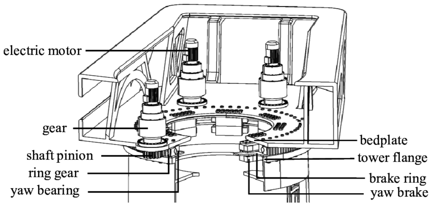
Figure 1Wind turbine yaw system. Reproduced from Kim and Dalhoff (2014).
In floating offshore wind turbines (FOWTs) with a single-point-mooring (SPM; SPM-FOWT) system, the mooring lines are attached to the platform at one single point, as shown in Fig. 2. In this way, the platform can freely rotate around it and align with environmental conditions (weather-vaning). This configuration allows the structural loads to be reduced and potentially the yaw system to be removed (Netzband et al., 2020), therefore reducing both the CAPEX and the OPEX (operational expenditure) of the FOWT.
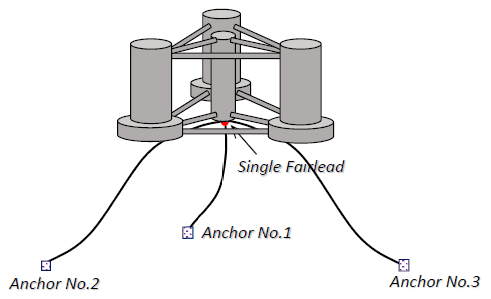
Figure 2Floating platform with an SPM configuration. Reproduced from Liu et al. (2018).
The SPM system was originally conceived for ships in order to align the vessel and reduce environmental loading caused by wind, currents and waves (Chakrabarti, 2005). Nevertheless, the differences in aerodynamics between ships and FOWTs make the alignment of the latter ones much less obvious.
The alignment of wind turbines without using a yaw mechanism is a subject that has been investigated since the last century, especially for onshore downwind wind turbines (Hansen, 1992). This type of turbine offers the advantage of having a passive yaw-alignment capacity that does not require heavy yaw mechanisms. Wanke et al. (2019) explain that, when there is some misalignment between the wind inflow and the rotor, the resulting forces on the rotor create a restorative yaw moment, which could align the rotor with the wind direction. However, for the downwind turbine analysed, there are other factors, such as the shaft tilt and wind shear, which avoid a total alignment of the rotor with the wind. This produces power losses that might make the use of a yaw mechanism compulsory again.
In the case of downwind SPM-FOWTs, it seems that a stable alignment between rotor and wind can be achieved. However, wave and current misalignment with wind could make an effective alignment of the rotor with wind difficult, according to Urbán et al. (2021).
On the other hand, upwind turbines are the most common topology used in the wind energy sector nowadays. For onshore and offshore bottom-fixed wind turbines (using upwind configuration), the use of the yaw mechanism at tower top is needed in order to align the rotor with the wind and maximise its power production. However, in the case of floating substructures, there is a possibility of taking advantage of the platform yaw (rotation around the vertical axis) degree of freedom (DoF) instead of using the yaw mechanism. Liu et al. (2018) analyse the upwind 5 MW National Renewable Energy Laboratory (NREL) turbine supported by the DeepCwind OC4 semi-submersible with an SPM configuration (Fig. 2). Their results indicate that a yaw moment appears in this kind of FOWT (caused by the rotor properties and aerodynamic asymmetry), which prevents the rotor alignment with the wind. This shows that there are considerable differences in the moments generated by a downwind and an upwind rotor. Although an SPM configuration helps to improve the rotor orientation, it is usually not enough to keep the rotor aligned with the wind. Therefore, it is necessary to add some active system that guarantees the optimum alignment of the wind turbine. The control system seems to be adequate for this purpose, especially the individual pitch control (IPC) strategy, which is able to generate asymmetric moments in the rotor.
IPC has been traditionally applied for load reduction based on blade-root bending moment measurements (Bossanyi, 2003). Alternatively, the usage of this strategy to improve the alignment of the wind turbine has also been tested. The IPC strategy based on nacelle yaw misalignment (known as yaw-by-IPC; Van Solingen, 2015) has been used for onshore wind turbines, generally with a downwind configuration (Van Solingen, 2015) but also with an upwind one (Zhao and Stol, 2007; Navalkar et al., 2014). It has also been superficially analysed in FOWTs (Urbán et al., 2021) but only for the downwind configuration, which does not take into account the challenges of controlling the alignment of upwind turbines.
The main objective of the current work is twofold: on the one hand, to understand the moments that generate a platform yaw drift in upwind SPM-FOWTs and, on the other hand, to demonstrate the capacity of the IPC strategy based on nacelle yaw misalignment to mitigate this drift.
To accomplish these objectives, this work is organised in the following sections. First, a description of the analysed system and its modelling is provided in Sect. 2. Then, the moment induced in yaw (or vertical) direction is explained in Sect. 3, both at rotor level and blade level. This moment causes a platform yaw drift in SPM-FOWTs, which is depicted in Sect. 4. Section 5 shows a description of the IPC strategy as an alternative to mitigate the yaw drift. After this, Sect. 6 presents the resulting advantages obtained with IPC. Finally, the main conclusions and possible future working lines are presented in Sect. 7.
The FOWT used in this study is the 5 MW NREL wind turbine (Jonkman et al., 2009) supported by the DeepCwind OC4 semi-submersible platform (Robertson et al., 2014), using an SPM configuration (Liu et al., 2018).
The work is carried out numerically using OpenFAST (Jonkman and Buhl, 2005), version 2.2.0. With this tool, the floater is modelled using HydroDyn with potential flow theory combined with Morison elements. The mooring lines are modelled using MoorDyn (mass mooring dynamics model), which is a lumped-mass dynamic model. In this study wave loading is not considered in order to show only the aerodynamic effects. For the sake of simplicity, the tower, blades and drive train are considered rigid.
The aerodynamic model used is the in-house aerodynamic module, called AeroVIEW (Aerodynamic Vortex Filament Wake), based on an implementation of a free vortex filament method (FVM) (Leishman et al., 2002) combined with an unsteady lifting line (LL) (Dumitrescu and Cardos, 1998) for the resolution of wake dynamics and blade loads, respectively. This kind of aerodynamic model has been widely used in the helicopter industry (Leishman et al., 2002; Ho et al., 2017) and is becoming more usual for offshore wind energy applications (Sebastian and Lackner, 2012; Kecskemety and McNamara, 2011). This happens because blade element momentum theory (BEMT) (Sørensen, 2016), which is the most widely used aerodynamic model in the wind energy industry, presents limitations when predicting loads in situations with large yaw or tilt misalignment between wind and rotor mainly because the root vortex is not well modelled (Sant, 2007; Rahimi et al., 2016; Gupta and Leishman, 2005). The FVM implemented in AeroVIEW has been validated previously in misaligned yaw conditions (Martín-San-Román et al., 2019, 2021) and allows the accurate inclusion of the effect of both the root vortex and the blade-tip vortex in both aligned and misaligned conditions.
The baseline turbine controller is an in-house development based on state-of-the-art control technologies for wind turbines. Gain-scheduling collective blade pitch control is applied for generator speed control above the rated level. Standard IPC based on blade-root bending moment is disabled in order to better showcase the effect of the yaw-by-IPC loop. A constant torque strategy is also applied in the above-rated region.
This section provides a description of the origin of the yaw moment generated by the wind turbine. The effects are described at rotor level in Sect. 3.1, while the phenomena causing yaw moment at blade level are discussed and assessed in Sect. 3.2. To improve the clarity of this discussion, the results shown in this section are performed with the onshore version of the wind turbine introduced in Sect. 2.
3.1 Rotor-level description of the causes of yaw moment
One of the causes of the yaw moment produced by the wind turbine is the generator torque around the rotor shaft. When the shaft has a certain angle with respect to the horizontal (tilt angle), this torque is projected into the vertical axis. Another effect that generates the yaw moment is the non-symmetric aerodynamic loads caused by non-perpendicular inflow winds to the rotor. In this paper the only cause of non-perpendicular winds is the tilt of the turbine. This tilt angle creates load variations in each of the blades as a function of the azimuthal position (as will be explained later in Sect. 3.2) that, when they are added, result in an additional non-zero moment around the vertical axis.
In addition, the shear of the wind inflow also generates an aerodynamic imbalance in the rotor that results in a third cause of yaw moment. In this case the yaw moment appears regardless of if the turbine has a tilt angle or not.
To show the influence of these effects, Fig. 3a presents the mean aerodynamic1 yaw moment Mz for a range of constant wind speeds at the rotor hub (or low-speed shaft) obtained with the FVM for the onshore 5 MW NREL wind turbine. The figure shows the results, with and without tilt angle, for two different wind conditions: under uniform wind speed and under a normal wind profile (NWP) with an exponential shear coefficient of 0.14, as defined in the guidelines (IEC, 2008).
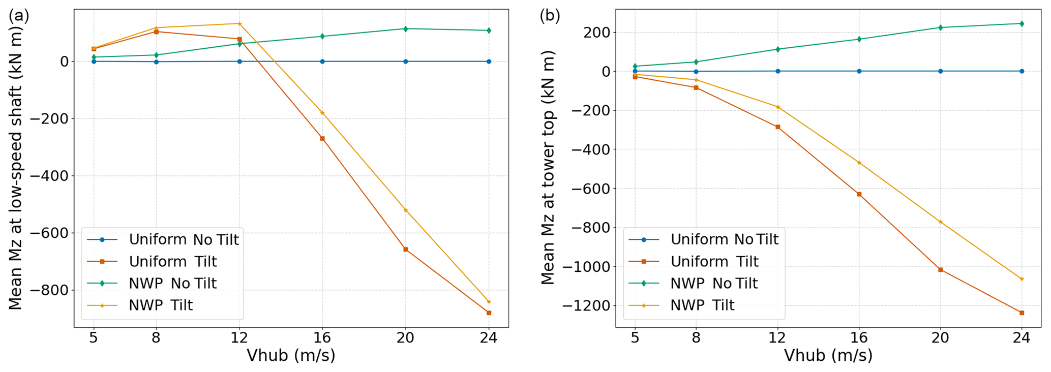
Figure 3Aerodynamic (a) and total (b) mean yaw moment Mz under constant wind speed without tilt (blue), constant wind speed with tilt (orange), NWP without tilt (green) and NWP with tilt (yellow).
When the shaft tilt is zero, the yaw moment is zero for the uniform wind, as there are no aerodynamic imbalances in the rotor. However, for the NWP condition, the wind shear introduces a positive moment around the vertical axis.
Both wind conditions (uniform wind and NWP) with shaft tilt show the same tendency. For wind speeds below the rated level (11.4 m s−1), the aerodynamic moment in yaw is positive. Nevertheless, at wind speeds above the rated level, the moment becomes negative with increasing values with wind speed. At these wind speeds, the uniform wind condition produces a larger negative moment than the NWP because the wind shear has an opposite effect on the moment.
As mentioned earlier, the total yaw moment transmitted from the hub to the tower top has an additional tilt-related component that comes from the generator torque projection in the vertical direction. Figure 3b shows the total mean yaw moment Mz at the tower top, which is the sum of the aerodynamic yaw moment from Fig. 3a and the respective generator torque projection.
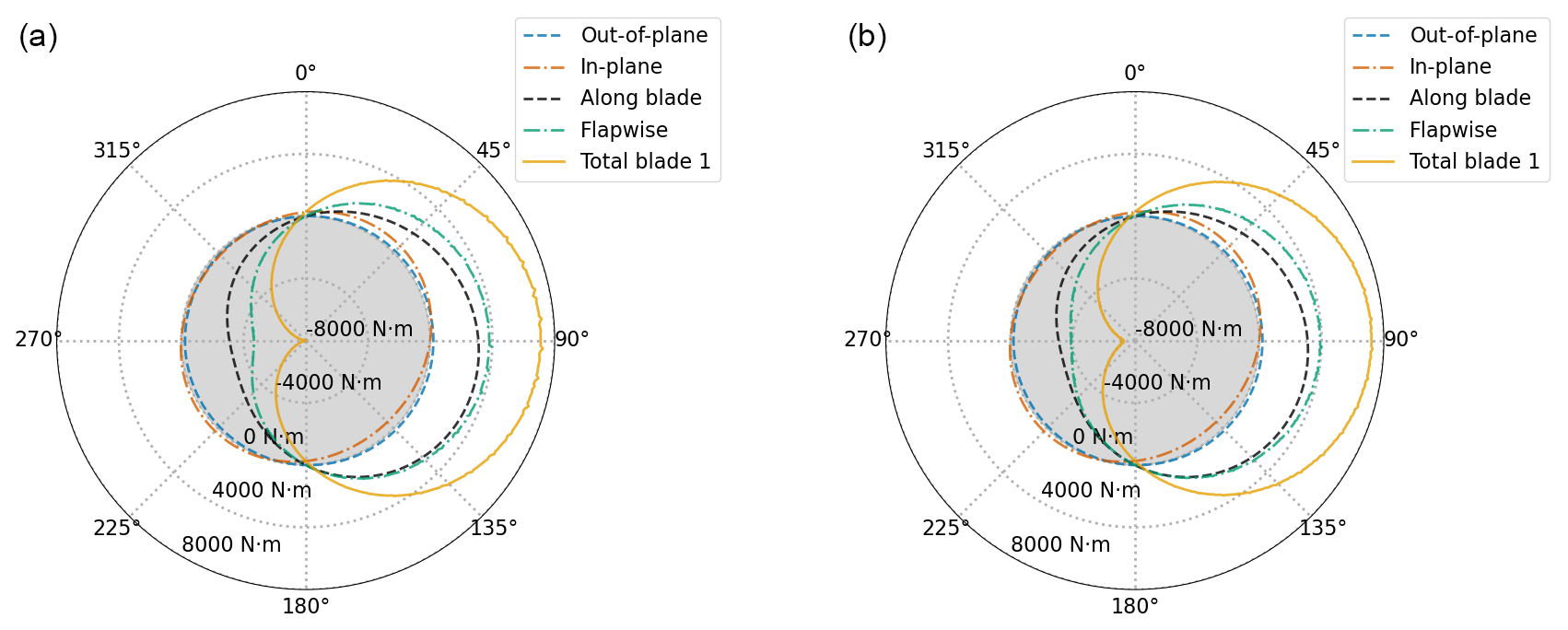
Figure 4Individual blade 1 load contributions (out-of-plane in dashed blue, in-plane in dashed–dotted orange, along blade in dashed black and flapwise in dashed–dotted green) to the yaw moment (solid yellow) at tower top with respect to azimuth (20 m s−1 uniform wind speed) with (a) and without (b) tilt.
Again, when the shaft tilt is zero, there is no yaw moment for the uniform wind, as there is no projection of the generator torque on the vertical axis and there are no aerodynamic imbalances in the rotor. The yaw moments for an NWP with no shaft tilt maintain the same tendency with respect to Fig. 3a but present larger magnitudes at the tower top due to the horizontal distance between the hub and the tower axis. Conversely to Fig. 3a, when the moment from the generator is included, the yaw moment is negative for all wind speeds for both wind conditions (uniform wind and NWP) including shaft tilt. This means, first, that the torque projection at wind speeds below the rated level is larger than the aerodynamic yaw moment, producing a net negative moment. Second, at wind speeds above the rated level, the generator torque contribution is added to the aerodynamic moment and results in a larger negative yaw moment at the tower top.
3.2 Blade-level analysis of the causes of yaw moment
This section aims to provide a better insight of the causes of yaw moment at blade level and what their impact is when the contribution of the three blades are added.
A detailed description of the effects causing the yaw moment at blade level is provided by Hansen (1992), which shows that there are four main moment contributions from each blade, namely out-of-plane force in the wind direction, in-plane force from each rotating blade, centrifugal force components along blade and the blade flapwise moment at blade root. All these loads are dependent on the blade azimuthal position.
With the intention of providing a better understanding of the physics that generate the yaw moment shown in Fig. 3, the four contributions to the yaw moment are shown in Fig. 4 for blade 1 of the onshore 5 MW NREL wind turbine. These contributions depend on the blade position, and, therefore, they are plotted as a function of the azimuthal position. The uniform wind speed is 20 m s−1. Figure 4a shows the case with tilt and Fig. 4b without tilt.

Figure 5Load contributions (out-of-plane in dashed blue, in-plane in dashed–dotted orange, along blade in dashed black and flapwise in dashed–dotted green) to the yaw moment at tower top combined for the three blades with respect to azimuth (20 m s−1 uniform wind speed) with (a) and without (b) tilt.

Figure 6Tower-top total yaw moment (solid green), contribution of each blade (blade 1 in dashed blue, blade 2 in dashed orange and blade 3 in dashed black) and corresponding combined contribution of the three blades with respect to azimuth (20 m s−1 uniform wind speed), with (a) and without (b) tilt.
The most important contributions to the yaw moment come from the blade flapwise moment and the moment caused by the centrifugal along-blade load. Figure 4 shows that they reach values around 4000 N m at 90∘ of azimuth and −4000 N m at 270∘, regardless of whether there is tilt or not. On the other hand, the out-of-plane and in-plane moment contributions are very close to 0 N m.
Figure 5 depicts the same breakdown of load contributions to the yaw moment at tower top as Fig. 4, but each one is summed up for the three blades. In the case with tilt (Fig. 5a), all the contributions from the three blades get compensated for over the rotor and have a zero value except for the flapwise contribution, which attains a value of −660 N m and remains constant with azimuth. In the case without tilt (Fig. 5b), the flapwise contribution resulting from the three blades is also zero, and therefore all the curves lie just over the 0 N m circumference. Please note that the centrifugal-force components along blade get cancelled when combining the three blades in both the tilt and no-tilt cases because it is assumed there is no mass imbalance in the rotor.
Accordingly, when all the load contributions are combined for the three blades (Fig. 6), the resulting moment Mz at tower top is −660 N m for the case with tilt (constant magnitude with respect to azimuthal position), as shown in Fig. 6a. In the case without tilt (Fig. 6b), the resulting moment is obviously zero, since all the contributions are zero when summed up for the three blades.
The above results show the relevance of the shaft tilt in the generation of yaw moment. In the case of onshore and offshore bottom-fixed wind turbines, this yaw moment is absorbed by the foundation. However, in the case of floating turbines these loads can influence the floater response, even if the moment magnitude is relatively small, due to the low stiffness in the platform yaw DoF in certain configurations, particularly in SPM systems. The next section presents the effect of this yaw moment Mz on the response of the DeepCwind OC4 semi-submersible platform using an SPM configuration.
As has been described in Sect. 3, the rotor induces a vertical moment Mz that can produce a yaw drift of the platform. The amplitude of this platform yaw rotation depends on the stiffness provided by the mooring system. This effect was reported in Jonkman and Musial (2010) for a spar floating platform with a symmetric mooring configuration. In the case of SPM configurations, the yaw stiffness of the mooring system is zero, and the effect of yaw moment is particularly critical.
In the current work, to illustrate and discuss the relevance of this yaw drift, the DeepCwind semi-submersible platform supporting the 5 MW NREL wind turbine is simulated using an SPM system, thus allowing it to freely yaw (Fig. 2).
Simulations are carried out under NWP steady wind speeds of 8, 12, 16 and 24 m s−1 and a calm sea (neither waves nor currents). The simulations begin with the initial conditions associated with the steady-state response of the FOWT under the same wind speeds. The baseline control strategy (see Sect. 2) has been used in this calculation.
Figure 7 shows the yaw drift of the platform under the different wind speeds. Below the rated wind speed, the yaw drift of the platform is close to zero. Conversely, over the rated wind speed, the drift of the platform becomes more relevant. This is consistent with the yaw moments shown in Fig. 3b for a fixed turbine.

Figure 7Platform yaw drift for 8 (blue), 12 (orange), 16 (black), 20 (green) and 24 m s−1 (yellow) (NWP).
At 16 m s−1 the drift of the platform stabilises around 39∘. At this yaw position, the destabilising yaw moments generated by the rotor are compensated for by restoring yaw moments that appear with the yaw rotation, such as the one due to the weather-vaning effect and the restoring moment that is generated at the rotor under yawed inflow wind, as reported by Wanke et al. (2019).
In order to avoid this yaw drift, the rotor must generate an additional vertical moment that compensates the yaw moments already discussed. This can be achieved with an IPC control strategy described in the next section.
As stated in the Introduction, the platform yaw response in upwind SPM-FOWTs is believed to be rectifiable by using IPC strategies. These strategies seem to be the right choice since, by controlling each blade independently, asymmetric moments can be generated in the rotor, which counteract those induced by the turbine (Sect. 3). However, it is still unknown whether an upwind SPM-FOWT is sensitive enough to the moments generated by an IPC strategy. In this section and the following one an answer to this question is provided.
The main objective of this IPC loop (yaw-by-IPC) is to keep the platform yaw angle near to zero, i.e. with zero mean and small deviations, in order to maximise power production and reduce structural loads. Nevertheless, the platform yaw angle may not be an available signal in FOWTs; hence misalignment between the wind's main direction and nacelle angle is used for the control loop, which can be calculated based on the measurement from a wind vane or another similar sensor. This misalignment is directly related to the platform yaw angle, particularly if the nacelle yaw DoF and the tower torsional mode are disregarded. However, there can be some differences, especially at low magnitudes and fast frequencies due to the wind's stochastic nature.
In order to reduce the differences between both signals, it is advised to apply a deadband (DB) and a low-pass filter to the misalignment signal (see Fig. 9). The DB used in the current work is based on a hyperbolic tangent function as provided by Navalkar et al. (2014) (Eq. 1):
where ϕDB is the resulting DB signal, ϕ is the measured raw misalignment, and ϵ is the DB width. The DB signal is then passed through a low-pass filter to remove high-frequency misalignments caused by wind.
In Fig. 8 a comparison between raw misalignment, filtered misalignment with DB and platform yaw angle is shown. As expected, the filtered misalignment with DB and the platform yaw angle are quite similar. However, the platform yaw is slower and usually has a phase difference with respect to the misalignment. Reducing the low-pass filter cut-off frequency makes the filtered misalignment with DB signal slower, but the phase difference increases. Therefore, a trade-off between these two competing objectives must be found.
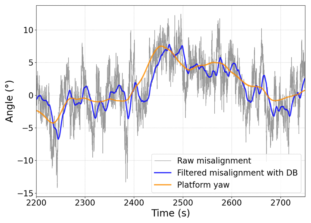
Figure 8Comparison between raw misalignment (grey), filtered misalignment with DB (blue) and platform yaw angle (orange).
The new controller is placed in a feedback loop (Fig. 9), in which the measured signal is the misalignment between wind main direction and nacelle angle. This signal is modified as explained above and then subtracted from the reference value (zero in this case, as the rotor must be aligned with the wind) and introduced into the controller. The controller output cannot be applied directly to the blades, as its output is in the non-rotatory frame, whereas the blades are in a rotatory one. To solve this, the commonly used inverse multi-blade coordinate (IMBC) transformation is used (Bossanyi, 2003). For three-bladed wind turbines, the IMBC is shown in Eq. (2).
where θ is the azimuth angle, βn is the nth blade pitch angle, βq is the controller output, and βd is zero. It is worth mentioning here that d and q non-rotatory axes correspond to rotor tilt and yaw axes, respectively. That is why, in this IPC case, βd has a null value and βq is directly the controller output.

Last, the demanded pitch angle for each blade is added to the collective pitch angle and applied to the corresponding blade. In summary, a complete block diagram of the yaw-by-IPC control system used is shown in Fig. 9.
To control the misalignment, a conventional proportional integral derivative (PID) controller is used. By adjusting the controller parameters, especially the derivative term, the phase difference between the platform yaw angle and the filtered misalignment can be overcome and a good alignment of the rotor achieved.
In this study, the PID controller parameters have been tuned using time domain simulations of the full non-linear model, as the linearised model presented reliability issues. Besides, due to differences among the dynamic responses for different wind speeds, non-linear control strategies (like gain scheduling) are expected to be necessary, although they have not been covered in the present paper, being part of future work.
In the next section results with and without yaw-by-IPC are shown and compared.
In this section, the effectiveness of the yaw-by-IPC loop strategy is evaluated by means of a set of dynamical simulations of the SPM-FOWT model with shaft tilt in a steady NWP and turbulent wind. In both cases the main wind direction is aligned with the wind turbine, and neither waves nor currents have been considered to allow for a better interpretation of the results.
6.1 Steady NWP wind
In the first case, an NWP wind speed of 20 m s−1 with shear of 0.14 is considered. According to the discussion in Sect. 3, for this wind speed the induced yaw moment is quite relevant (Fig. 3b), and its effects will be clearly observed. It should be borne in mind that, as wind heading is always 0∘, rotor misalignment and platform yaw are always equal because there is no nacelle yaw system active and tower torsional mode is disregarded. Hence, neither the DB nor the low-pass filter explained in Sect. 5 is necessary.
In Fig. 10 it can be observed how the platform yaw is unstable if no yaw drift mitigation strategy is used (baseline controller; see Sect. 2), and it rapidly takes values that are too high, which would reduce the power production and probably cause the shutdown of the machine. However, using the yaw-by-IPC loop, platform yaw is successfully controlled.
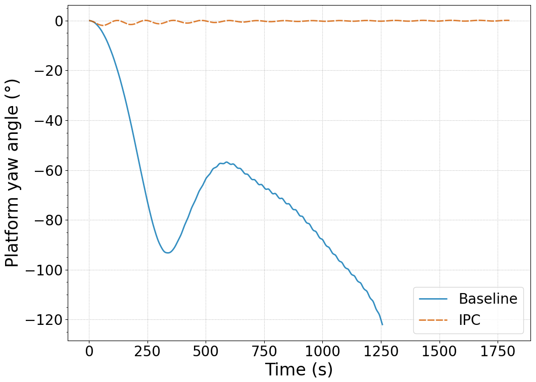
Figure 10Platform yaw angle with (dashed orange) and without yaw-by-IPC loop (solid blue) and an NWP wind speed of 20 m s−1.
As well as controlling the platform yaw, regulation of generator speed and power regulation is also appropriately achieved, reaching the rated value (1173.7 rpm and 5 MW, respectively) after the transient period. Without the yaw-by-IPC control these two variables undergo large variations due to the yaw instability, which are not admissible for a wind turbine. A comparison of the two variables, with and without yaw-by-IPC, can be seen in Fig. 11.

Figure 11Generator speed (a) and generator power (b) with (dashed orange) and without yaw-by-IPC loop (solid blue) and an NWP wind speed of 20 m s−1.
Besides, other platform DoFs, such as pitch or roll, which are not represented herein for simplicity, are maintained within acceptable levels when the yaw-by-IPC is applied.
In Fig. 12a the pitch angle of the three blades for the simulated case is plotted looking downwind against the azimuth angle of blade number 1. With this figure it is possible to see how the IPC varies the pitch angle in one rotation to create a restorative moment. The graph can be divided into two halves: the right one, which goes from azimuth 0 to 180∘, and the left one, which goes from 180 to 360∘. At the transition points between halves (0 and 180∘ points), the pitch angle of blade 1 adopts the value of the collective pitch control (17∘). When the FOWT platform presents negative yaw misalignment, like in this case, this means that the right half of the rotor is placed upwind from the nacelle (is more advanced towards the wind) and the other one downwind. In order to re-align the rotor, different thrust forces must be generated in each half to create a moment. Thus, a higher thrust force must be applied to the right half (azimuth between 0 and 180∘), which is achieved by reducing the pitch angle of blade 1 in that sector while increasing it in the left half. This is clearly shown for blade 1 in the figure, and for blades 2 and 3, it is shown with the corresponding phase difference of 120 and 240∘, respectively.

Figure 12Blade pitch angles (collective blade angle in blue, blade 1 in orange, blade 2 in black and blade 3 in green) for yaw-by-IPC and an NWP wind speed of 20 m s−1 with respect to azimuthal position (a) and time (b).
Similarly, in Fig. 12b the three blades' pitch angles are shown against time. As can be seen, the three signals have a sinusoidal form and a phase difference of 120∘, analogous to other IPC strategies in three-bladed wind turbines.
6.2 Turbulent wind
In the second case, a turbulent wind profile is used. Similar to Sect. 6.1, a mean wind speed of 20 m s−1 is selected to clearly showcase the effects under study. A turbulence intensity of 16 % is used, in accordance with values for class A offshore wind turbines in the standards (IEC, 2019).
Unlike the case with constant wind speed, now misalignment between rotor and main wind direction is obviously not equal to platform yaw due to the wind's stochastic nature. This makes necessary the previously described signal processing (DB and filter) of the measured signal.
As can be seen in Fig. 13, the platform yaw angle is successfully controlled. As in the case with a steady NWP of 20 m s−1, FOWT instability is avoided by mitigating the yaw drift, and the platform mean yaw angle is brought near zero. Due to wind turbulence, it is not possible to achieve a constant alignment. However, it is usually maintained within ±10∘, and its maximum absolute value never exceeds 15∘, which are considered to be acceptable values. It is worth noticing that the platform yaw response without IPC controller has a drift motion similar to the results observed for the cases of steady winds. Thus, the fluctuation from the turbulent winds does not produce important differences in the platform yaw drift.
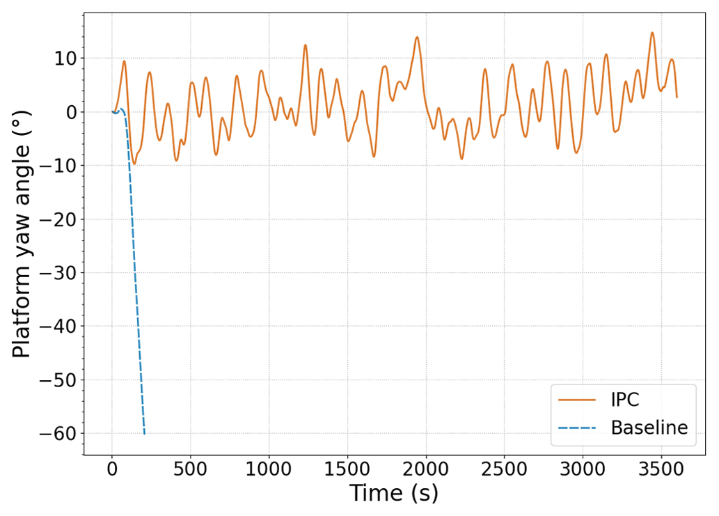
Figure 13Platform yaw angle with (solid orange) and without yaw-by-IPC loop (dashed blue) and turbulent mean wind speed of 20 m s−1.
Apart from keeping the wind turbine aligned with the wind, the yaw-by-IPC loop does not interfere with generator speed and power regulation, similar to the previous steady case. Generator speed and power signals can be observed in Fig. 14. Overspeed and overpower values are kept always below 4 %, which indicates a very tight regulation.
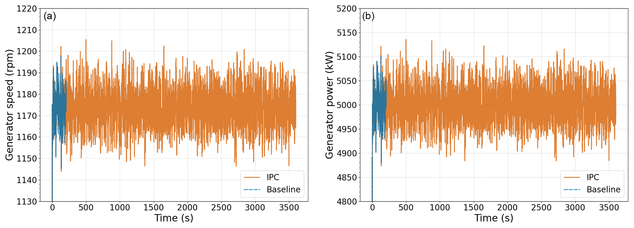
Figure 14Generator speed (a) and generator power (b) with (solid orange) and without yaw-by-IPC loop (dashed blue) and turbulent mean wind speed of 20 m s−1.
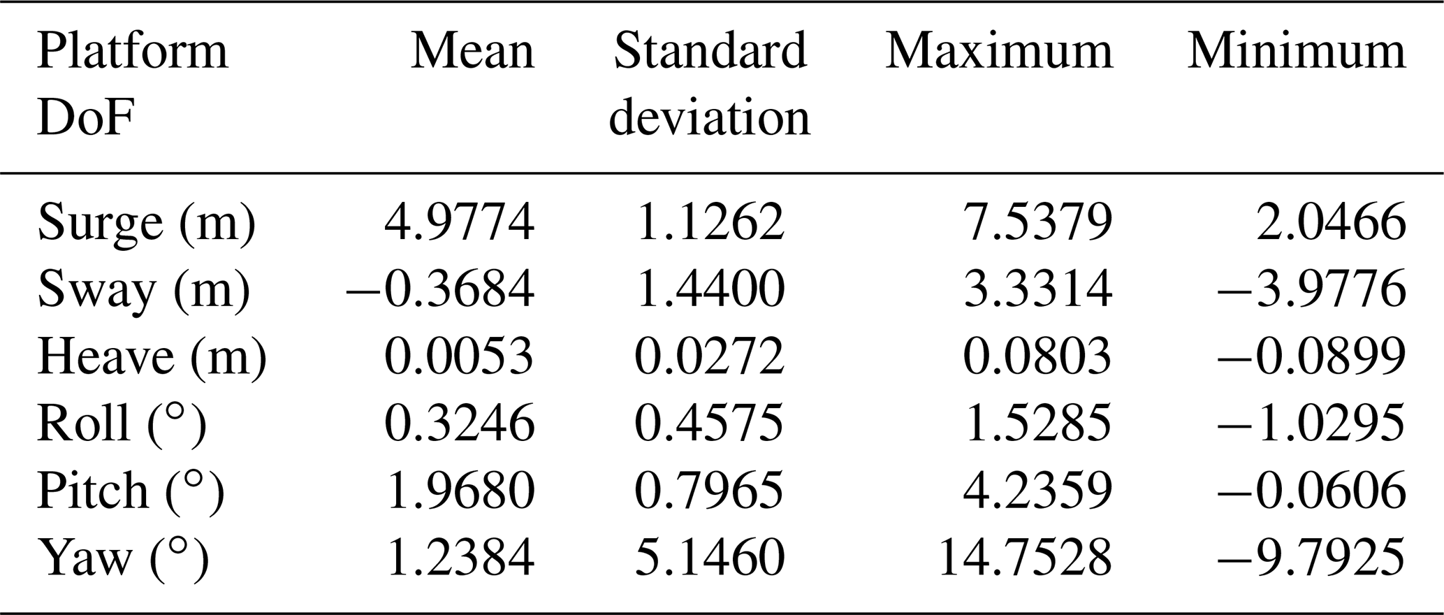
Furthermore, this strategy maintains the rest of the platform DoFs within acceptable ranges, as shown in Table 1.
Table 1Platform DoF statistical values for a turbulent mean wind speed of 20 m s−1 with yaw-by-IPC.
The alignment of the FOWT, as well as ensuring a good speed and power regulation and minimisation of other platform DoFs, is strongly believed to have a positive impact on the mooring-line tensions, as in other system loads. Nevertheless, this analysis is out of the scope of this paper and will be carried out in detail in future studies.
All in all, the yaw-by-IPC loop has been demonstrated to maintain the alignment of upwind FOWTs with the main wind direction, while it allows a smooth power and speed regulation and reduces platform motions.
This work has presented the relevance of the yaw moment generated by an upwind rotor for the dynamics of an offshore floating wind turbine with an SPM system. This effect tends to misalign the system with respect to the wind direction and can potentially destabilise it. Additionally, this work has also demonstrated the capability of an IPC control strategy based on the nacelle yaw misalignment to mitigate the effect of such moments on the platform yaw drift.
The yaw moment induced by the turbine increases with wind speed, but its magnitude highly depends on the shaft tilt angle. The main contributors to this tilt-related moment are shown to be the projection of the generator torque on the vertical axis and the blades' flapwise load, provided there is no rotor mass imbalance.
For onshore and offshore bottom-fixed wind turbines, this tilt-related moment is absorbed by the foundation without further consequences. Conversely, in FOWTs, particularly those with an SPM system, the effect of the vertical moment induced by the turbine becomes especially important due to the lack of stiffness in yaw rotation to counteract it. In that case, the FOWT response results in a platform yaw drift that depends on the magnitude of wind speed and can strongly impact the wind turbine power production and loads.
To avoid this yaw drift, a solution based on an IPC strategy is presented. This control strategy is capable of generating asymmetric moments in the rotor that counteract the destabilising ones and keep the turbine aligned. This IPC strategy, based on yaw misalignment measurements and known as yaw-by-IPC, had already been tested in other turbine configurations in the past but not for the challenging case of upwind SPM-FOWTs.
Simulations for the SPM DeepCwind OC4 platform supporting the 5 MW NREL wind turbine have shown that the yaw-by-IPC loop is an adequate strategy to avoid the yaw drift in upwind SPM-FOWTs. At the same time, it does not affect the generator speed and power regulation, and it maintains other platform DoFs within acceptable levels.
In future work, a non-linear control strategy (like gain scheduling) will be designed and parameterised in order to run simulations in the whole wind speed range. Besides, more complex and realistic environmental conditions will be analysed and tested, including the simultaneous effect of waves, ocean currents and misaligned wind. This will allow the feasibility assessment under multiple misalignment sources. At control level, the effect on structural loads and mooring-line tensions will be assessed in detail. Furthermore, a comparison between an SPM-FOWT (with IPC) and an FOWT with a conventional mooring-line configuration (without IPC) will be carried out in order to justify the usage of this type of configuration.
The code is not publicly accessible due to intellectual property management processes.
The data that support the findings of this study are available from the corresponding author upon reasonable request.
ISF designed the controller, post-processed the simulations, analysed the results and wrote the manuscript. FV analysed the yaw moment produced in both onshore and floating offshore wind turbines, developed the hydrodynamic model, and wrote the manuscript. RMSR developed the aerodynamic model, ran the simulations and reviewed the manuscript. IE and JAA reviewed and edited the manuscript.
At least one of the (co-)authors is a member of the editorial board of Wind Energy Science. The peer-review process was guided by an independent editor, and the authors also have no other competing interests to declare.
Publisher's note: Copernicus Publications remains neutral with regard to jurisdictional claims in published maps and institutional affiliations.
This work has been conducted within the ARCWIND project (Adaptation and implementation of floating wind energy conversion technology for the Atlantic region; http://www.arcwind.eu/, last access: 28 February 2023), which is co-financed by the European Regional Fund through the Interreg Atlantic Area Programme under contract EAPA 344/2016.
The authors also want to thank the government of Navarre for the funding provided by the “Ayudas para la contratación de doctorandos y doctorandas por empresas y organismos de investigación y difusión de conocimientos: doctorados industriales 2019–2021” programme that has been used for the development of AeroVIEW.
This research has been supported by the Interreg Atlantic Area Programme under contract EAPA 344/2016 and the government of Navarre (Ayudas para la contratación de doctorandos y doctorandas por empresas y organismos de investigación y difusión de conocimientos: doctorados industriales 2019–2021).
This paper was edited by Jan-Willem van Wingerden and reviewed by two anonymous referees.
Bossanyi, E. A.: Individual Blade Pitch Control for Load Reduction, Wind Energy, 6, 119–128, https://doi.org/10.1002/we.76, 2003. a, b
Chakrabarti, S. K.: Handbook of Offshore Engineering, 1st Edn., Elsevier, ISBN 978-0-08-044381-2, 2005. a
Dumitrescu, H. and Cardos, V.: Wind turbine aerodynamic performance by lifting line method, International Journal of Rotating Machinery, 4, 141–149, https://doi.org/10.1155/S1023621X98000128, 1998. a
Gupta, S. and Leishman, J.: Comparison of momentum and vortex methods for the aerodynamic analysis of wind turbines, in: 43rd AIAA Aerospace Sciences Meeting and Exhibit, 10–13 January 2005, Reno, Nevada, https://doi.org/10.2514/6.2005-594, 2005. a
Hansen, A. C.: Yaw Dynamics of Horizontal Axis Wind Turbines, Tech. rep., NREL, https://doi.org/10.2172/10144778, 1992. a, b, c
Ho, J. C., Yeo, H., and Bhagwat, M.: Validation of rotorcraft comprehensive analysis performance predictions for coaxial rotors in hover, J. Am. Helicopter Soc., 62, 1–13, https://doi.org/10.4050/jahs.62.022005, 2017. a
IEC: IEC 61400-1 Wind Turbines – Part 1: Design Requirements, https://www.une.org/encuentra-tu-norma/busca-tu-norma/iec?c=26423 (last access: 27 February 2023), 2008. a
IEC: IEC TS 61400-3-2 Wind Energy Generation Systems – Part 3-2: Design Requirements for Floating Offshore Wind Turbines, https://www.une.org/encuentra-tu-norma/busca-tu-norma/iec/?c=29244 (last access: 2 February 2023), 2019. a
Jonkman, J. and Musial, W.: Offshore Code Comparison Collaboration (OC3) for IEA Task 23 Offshore Wind Technology and Deployment, Tech. rep., NREL, Golden, CO, https://doi.org/10.2172/1004009, 2010. a
Jonkman, J. M. and Buhl, M. L.: FAST User's Guide, OSTI.GOV, https://doi.org/10.2172/15020796, 2005. a
Jonkman, J. M., Butterfield, S. B., Musial, W., and Scott, G.: Definition of a 5 MW Reference Wind Turbine for Offshore System Development, Tech. rep., NREL, https://doi.org/10.1115/1.4038580, 2009. a
Kecskemety, K. and McNamara, J.: The Influence of Wake Effects and Inflow Turbulence on Wind Turbine Loads, AIAA J., 49, 2564–2576, https://doi.org/10.2514/1.J051095, 2011. a
Kim, M.-G. and Dalhoff, P. H.: Yaw Systems for Wind Turbines – Overview of Concepts, Current Challenges and Design Methods, in: Sci. Mak. Torque from Wind, vol. 524, Institute of Physics Publishing, Copenhagen, https://doi.org/10.1088/1742-6596/524/1/012086, 2014. a
Leishman, J. G., Bhagwat, M. J., and Bagai, A.: Free-vortex filament methods for the analysis of helicopter rotor wakes, J. Aircraft, 39, 759–775, https://doi.org/10.2514/2.3022, 2002. a, b
Liu, Y., Yoshida, S., Yamamoto, H., Toyofuku, A., He, G., and Yang, S.: Response Characteristics of the DeepCwind Floating Wind Turbine Moored by a Single-Point Mooring System, Appl. Sci., 8, 2306, https://doi.org/10.3390/app8112306, 2018. a, b, c
Martín-San-Román, R., Azcona-Armendáriz, J., and Cuerva-Tejero, A.: Lifting line free wake vortex filament method for the evaluation of floating offshore wind turbines. First step: validation for fixed wind turbines, in: IWOTC, ASME 2019 2nd International Offshore Wind Technical Conference, 3–6 November 2019, St. Julian's, Malta, https://doi.org/10.1115/IOWTC2019-7540, 2019. a
Martín-San-Román, R., Benito-Cia, P., Azcona-Armendáriz, J., and Cuerva-Tejero, A.: Validation of a free vortex filament wake module for the integrated simulation of multi-rotor wind turbines, Renew. Energ., 179, 1706–1718, https://doi.org/10.1016/j.renene.2021.07.147, 2021. a
Navalkar, S. T., Van Wingerden, J. W., and Van Kuik, G. A. M.: Individual Blade Pitch for Yaw Control, in: Sci. Mak. Torque from Wind, vol. 524, Institute of Physics Publishing, Roskilde, https://doi.org/10.1088/1742-6596/524/1/012057, 2014. a, b
Netzband, S., Schulz, C. W., and Abdel-Maksoud, M.: Self-Aligning Behaviour of a Passively Yawing Floating Offshore Wind Turbine, Sh. Technol. Res., 67, 15–25, https://doi.org/10.1080/09377255.2018.1555986, 2020. a
Pfaffel, S., Faulstich, S., and Rohrig, K.: Performance and Reliability of Wind Turbines: A Review, Energies, 10, 1904, https://doi.org/10.3390/en10111904, 2017. a
Rahimi, H., Hartvelt, M., Peinke, J., and Schepers, J. G.: Investigation of the current yaw engineering models for simulation of wind turbines in BEM and comparison with CFD and experiment, J. Phys.: Conf. Ser., 753, 022016, https://doi.org/10.1088/1742-6596/753/2/022016, 2016. a
Robertson, A., Jonkman, J., Masciola, M., Song, H., Goupee, A., Coulling, A., and Luan, C.: Definition of the Semisubmersible Floating System for Phase II of OC4, NREL, https://doi.org/10.2172/1155123, 2014. a
Sant, T.: Improving BEM-based Aerodynamic Models in Wind Turbine Design Codes, PhD thesis, Delft University of Technology, http://resolver.tudelft.nl/uuid:4d0e894c-d0ad-4983-9fa3-505a8c6869f1 (last access: 28 February 2023), 2007. a
Sebastian, T. and Lackner, M. A.: Development of a free vortex wake method code for offshore floating wind turbines, Renew. Energ., 46, 269–275, https://doi.org/10.1016/j.renene.2012.03.033, 2012. a
Sørensen, J. N.: General Momentum Theory for Horizontal Axis Wind Turbines, Research Topics in Wind Energy, vol. 4, Springer International Publishing, Cham, https://doi.org/10.1007/978-3-319-22114-4, 2016. a
Stehly, T., Beiter, P., and Duffy, P.: 2019 Cost of Wind Energy Review, Tech. rep., NREL, Golden, CO, https://doi.org/10.2172/1756710, 2020. a
Urbán, A. M., Voltà, L., Lio, W. H., and Torres, R.: Preliminary Assessment of Yaw Alignment on a Single Point Moored Downwind Floating Platform, in: EERA DeepWind, vol. 2018, Institute of Physics Publishing, Trondheim, https://doi.org/10.1088/1742-6596/2018/1/012043, 2021. a, b
Van Solingen, E.: Control Design for Two-Bladed Wind Turbines, PhD thesis, Technische Universiteit Delft, Delft, https://doi.org/10.4233/uuid:abb59ca8-877a-4599-8ea9-6f23c46d39b9, 2015. a, b
Wanke, G., Hansen, M. H., and Larsen, T. J.: Qualitative yaw stability analysis of free-yawing downwind turbines, Wind Energ. Sci., 4, 233–250, https://doi.org/10.5194/wes-4-233-2019, 2019. a, b
WindEurope: Floating Offshore Wind, https://windeurope.org/intelligence-platform/reports/ (last access: 28 February 2023), 2020. a
Zhao, W. and Stol, K. A.: Individual Blade Pitch for Active Yaw Control of a Horizontal-Axis Wind Turbine, in: AIAA Aerosp. Sci. Meet. Exhib., AIAA, Reno, https://doi.org/10.2514/6.2007-1022, 2007. a
The moment generated in the rotor is referred herein as aerodynamic moment because it is assumed that there is no mass imbalance in the rotor.
- Abstract
- Introduction
- System description and modelling
- Description of the yaw moment caused by the wind turbine
- Effect of the yaw moment from the turbine on the platform dynamics
- Individual pitch control strategy to mitigate platform yaw drift
- Results
- Conclusions and future work
- Code availability
- Data availability
- Author contributions
- Competing interests
- Disclaimer
- Acknowledgements
- Financial support
- Review statement
- References