the Creative Commons Attribution 4.0 License.
the Creative Commons Attribution 4.0 License.
 | 22 Oct 2025
Disentangling wake and projection effects in the aerodynamics of wind turbines with curved blades
Mac Gaunaa
Georg Raimund Pirrung
Kenneth Lønbæk
Advancements in wind turbine technology have led to larger, more flexible blades and an increasing interest in aerodynamic load calculations and design optimization of blades featuring significant sweep, prebend or coning. High-fidelity blade-resolved computational fluid dynamics (CFD) simulations provide precise rotor performance predictions but are computationally expensive. In contrast, the low-fidelity blade element momentum (BEM) method is computationally efficient but unable to model wake-induced effects of non-straight blades and coned rotors. To bridge this gap, mid-fidelity aerodynamic models, which balance accuracy and computational efficiency, are essential for design optimization tasks. Consistent aerodynamic benchmarks are crucial to effectively evaluate these models, particularly for modeling wake-induced effects across different blade geometries. Previous studies have typically used the same chord and twist distributions across different curved blade geometries. However, this approach introduces inconsistencies, as it does not guarantee the same local aerodynamic conditions (e.g., angle of attack and local thrust coefficient) along the blade span due to projection effects of velocities and forces between the 2-D airfoil section and the 3-D flow. Consequently, wake-induced effects on loading and induction become entangled with projection effects, hindering the clear evaluation of how wake-induced effects, due solely to blade curvature, influence the loads and induction. This study introduces a framework to disentangle wake-induced and projection effects in aerodynamic comparisons of curved blades. Within the BEM framework, we derive the necessary modifications to the chord and twist distributions of curved blades, ensuring the same spanwise circulation distribution as a baseline straight blade. These adjustments remove projection-driven discrepancies, enabling a consistent evaluation of wake-induced effects on loading and induction. Numerical validations using BEM and CFD confirm the effectiveness of these modifications. Additionally, projection effects in existing CFD results can be effectively isolated and removed. Using this framework, we discovered a novel insight from analysis of the CFD results: the wake-induced effects of moderate blade sweep and prebend can be modeled independently and then superimposed. This previously inaccessible insight significantly simplifies the modeling process and provides valuable guidance for developing mid-fidelity engineering aerodynamic models. Overall, this study advances the understanding of blade sweep and prebend effects on normal and tangential aerodynamic loads, supporting future blade design optimization.
- Article
(16744 KB) - Full-text XML
- BibTeX
- EndNote


Advancements in wind turbine design and manufacturing have resulted in modern horizontal-axis wind turbine (HAWT) blades that are significantly more flexible than the stiff blades of the 1980s, leading to larger elastic deformations. In parallel, there is growing interest in innovative blade designs with non-straight blade shapes and coned rotor configurations. Examples include backward swept blades for passive load alleviation via geometric bend–twist coupling (Liebst, 1986; Zuteck, 2002; Larwood and Zutek, 2006; Manolas et al., 2018), highly flexible blades that exhibit significant out-of-plane deflections (Loth et al., 2012), downwind rotor configurations optimized for conditions of low specific wind speed (Madsen et al., 2020b) and aeroelastically tailored curved blade tip designs (Barlas et al., 2021; Madsen et al., 2022). These unconventional blade geometries present significant challenges for aerodynamic load calculation and design optimization. It is crucial to model their aerodynamic effects on loads correctly, particularly in numerical optimization tasks. Using models that cannot correctly capture these effects may lead to blade designs that deviate significantly from the actual optimal design (Li et al., 2022a; Zahle et al., 2024), and unforeseen aeroelastic instabilities may occur. The blade element momentum (BEM) method (Glauert, 1935; Madsen et al., 2020a), which relies on two-dimensional (2-D) airfoil polars,1 has been widely used for aerodynamic and aeroelastic load calculations due to its computational efficiency. However, the BEM method is strictly applicable only to straight blades forming a planar rotor (Li et al., 2022b, 2024), as it does not account for the impact of changes in wake geometry on inductions and loads. Consequently, BEM is considered a low-fidelity method and is often used as the baseline for comparison. On the high-fidelity end, Reynolds-averaged Navier–Stokes (RANS) simulations with fully resolved three-dimensional (3-D) blade geometries (commonly referred to as computational fluid dynamics or CFD) can accurately model the effects of blade geometry on wake and loads since the entire flow field is solved. Despite its accuracy, CFD's high computational cost limits its practicality for direct use in design optimizations or repetitive aeroelastic calculations. Mid-fidelity engineering aerodynamic models, which include the effects of wake geometry on inductions to different extents, lie between BEM and CFD. If a mid-fidelity model can capture the primary aerodynamic effects of curved blades with significantly lower computational demands than CFD, it becomes a favorable alternative. Examples include the blade element vortex cylinder (BEVC) method for prebend effects (Li et al., 2022b), a vortex-based coupled near- and far-wake model for sweep effects (Li et al., 2022d), corrections to Prandtl's tip-loss factor for sweep effects (Fritz et al., 2022), higher-fidelity lifting-line (LL) approaches (Phillips and Snyder, 2000; Ramos-García et al., 2016; Boorsma et al., 2020; Branlard et al., 2022), and the actuator line (AL) method (Sørensen and Shen, 2002; Meyer Forsting et al., 2019; Martínez-Tossas and Meneveau, 2019). Before confidently applying these models for load calculations and design optimization, consistent aerodynamic benchmarks (Barlas et al., 2022; Horcas et al., 2023) or even aeroelastic benchmarks (Behrens de Luna et al., 2022; Zahle et al., 2024) are essential.
Two primary effects of the curved blade geometry or rotor coning on inductions and loads have been identified, termed “projection effects” and “wake-induced effects”. First, projection effects arise from the projection of velocities and loads between the 3-D turbine blade and the 2-D airfoil section under the cross-flow principle (Hoerner and Borst, 1985). For instance, sweeping the blade backward increases the flow angle perceived by the 2-D airfoil section, as shown analytically in Li et al. (2024). Second, wake-induced effects result from changes in the wake geometry due to the curved blade geometry. For instance, the starting position of the trailed vortex for a backward swept blade follows the blade and is shifted within the rotor plane compared to a straight blade, as described and illustrated in Li et al. (2018, 2022d). Induction changes also arise from contributions of the curved bound vortex, as analyzed and visualized in Li et al. (2018, 2020). Figure 1 provides a qualitative illustration of these two effects.
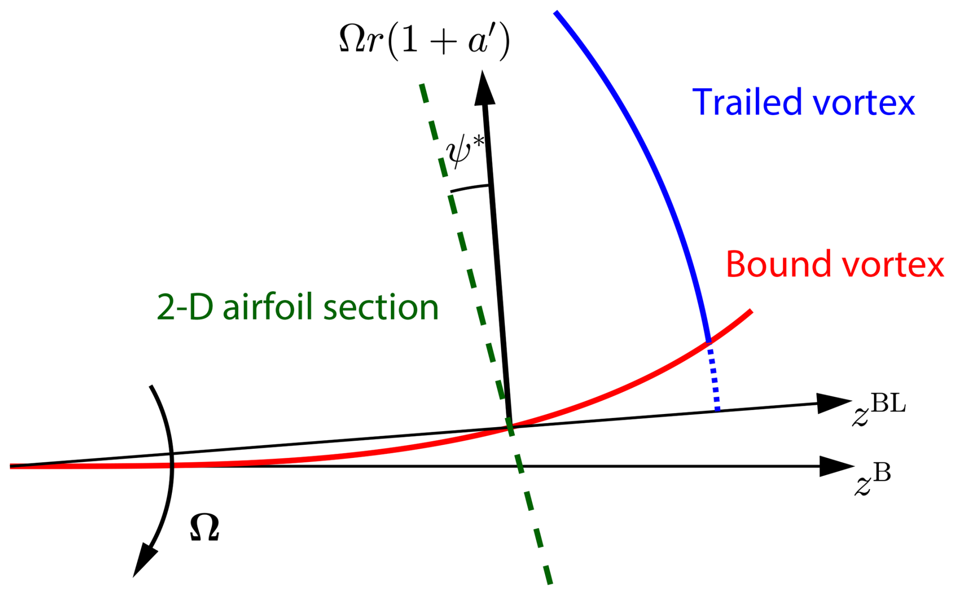
Figure 1Qualitative illustration of the projection effect and the wake-induced effect for a backward swept blade. The projection effect refers to the geometric projection of velocities and loads between the 3-D turbine blade and the 2-D airfoil section. For example, projecting the tangential velocity component (black arrow) onto the 2-D airfoil section plane (dashed green line) introduces a scaling by the cosine of the effective sweep angle ψ*. The wake-induced effect refers to changes in the wake geometry resulting from blade curvature. In this example, the trailed vortex (blue line) originates from a shifted azimuthal location compared to a straight blade, with the segment shown as a dotted blue line missing. Additionally, the curvature of the bound vortex (red line), which follows the chord line of the swept blade, introduces additional induction effects; these are considered part of the wake-induced effects in this work. A correct implementation of BEM theory captures projection effects but does not account for wake-induced effects. Note that the 2-D airfoil section is locally perpendicular to the curved blade line and the tangential velocity component is perpendicular to the radial direction (i.e., the zBL axis).
In previous comparisons, the same chord and twist distributions have typically been used for both curved blades and the reference baseline straight blade (Sun et al., 2020, 2021; Li et al., 2022b, c, d; Horcas et al., 2023). For example, Li et al. (2022d) developed a mid-fidelity engineering aerodynamic model for swept blades, which demonstrated significantly better agreement with LL and CFD predictions than BEM results. Similarly, the BEVC model introduced in Li et al. (2022b) also showed substantially improved agreement with LL and CFD compared to BEM. While improved agreement with higher-fidelity LL and CFD over BEM suggests that mid-fidelity models capture wake-induced effects better than BEM models do, the comparisons in both studies do not show the pure effect of the change in geometry because the projection effects (which change the local flow conditions and thus local loading) and the wake-induced effects (the primary focus) are entangled. Moreover, it remains unclear whether having blade sweep or prebend provides aerodynamic benefits, as blades with different geometries may operate under different conditions due to projection effects (e.g., different angles of attack and local thrust coefficients). From a performance evaluation point, it may indeed be relevant to consider the combined effect due to projection and wake. However, for the purposes of aerodynamic model development, benchmarking and design optimization, it is crucial to disentangle these effects to understand how blade curvature alone influences the wake and the induction. To achieve consistent comparisons, it is essential to minimize projection effects such that the influence of wake geometry on inductions and loads is highlighted. Recent research (Li et al., 2024) demonstrated that, within the BEM method, if a curved blade has a radial circulation distribution Γ(r) identical to that of a straight blade, it will see the same induced velocities. Further, the loads due to the lift force will also be identical between curved and straight blades; only negligible differences due to the drag force remain.
Building on this insight, the present study directly extends the theoretical work in Li et al. (2024) by deriving the necessary modifications to the chord and twist distributions to ensure curved blades achieve this equivalence. We also discuss important theoretical considerations for aerodynamic comparisons, including curved blade length corrections, non-circulatory loads and the choice of loads for comparison. These theoretical developments are then tested in a comprehensive numerical investigation. We first revisit previous numerical comparisons (Li et al., 2018, 2022b, d), examining blades with only sweep and with only prebend. After this, we extend the analysis to curved blades with combined sweep and prebend, which have significant stronger projection effects. Comparisons are made between BEM and CFD results using both the original setup (unmodified chord and twist distributions, as in previous studies) and the modified setup (with modified distributions, as introduced in the present work). These comparisons aim to evaluate whether the modified setup effectively isolates projection effects, thereby enabling a consistent aerodynamic evaluation of the isolated effect of the non-straight blade geometry on the wake induction. Leveraging the framework derived in this study, we use CFD results to explore the potential of modeling wake-induced effects of sweep and prebend independently and assessing whether their superposition enables simplified engineering aerodynamic modeling methods.
The remainder of the paper is organized as follows. Section 2 presents the theoretical foundation within the BEM method and derives the BEM-based chord and twist modifications that remove projection effects. Section 3 details the aerodynamic models used for comparison, including the BEM implementation and the CFD setup. Section 4 compares the results of the original and modified curved blades under different operational conditions. Section 5 summarizes the key findings and their implications for future aerodynamic modeling and blade design.
This section presents a consistent approach for modeling curved blades within the blade element momentum (BEM) framework, adapted from Madsen et al. (2020a) with specific modifications. In this approach, the drag force contribution is excluded during momentum balancing to determine the inductions (Wilson and Lissaman, 1974; Branlard, 2017). The radial induction model proposed by Madsen et al. (2020a) is omitted, as it is not derived from momentum theory and is not standard in most BEM implementations. However, it is acknowledged that radial induction can contribute to axial and tangential loads if the blade is curved. The rotor is assumed to operate at a constant rotational speed with uniform inflow applied perpendicularly to the rotor plane, eliminating effects such as rotor yaw, tilting and wind shear.
Precise definitions of airfoil section alignments and coordinate systems are crucial for a consistent BEM implementation. In the present work, the blade planform is defined along a local main axis, with 2-D airfoil sections oriented perpendicularly to it. Unlike planar rotors with straight blades, which have a radially oriented main axis, this analysis incorporates tangential and axial components of the local blade axis to account for blade sweep and prebend. For simplicity, the main axis is initially defined as the chord line of the blade. The lift force direction is then directly determined using the flow velocity at the main axis (Øye, 1981; Bergami and Gaunaa, 2012; Li et al., 2022c). Then, the relationship between the chord and twist distributions of the curved blade and the baseline straight blade, which enables the same circulation distribution, is also derived. Afterwards, the assumption that the airfoils are aligned to the chord line is relaxed and the equations and conclusions are generalized.
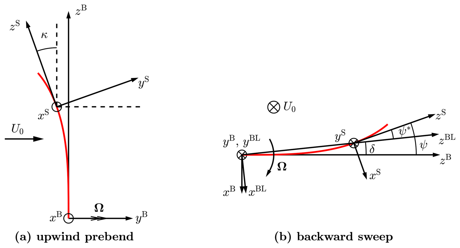
Figure 2Illustration of different coordinate systems used in the present work. (a) Blade with only upwind prebend, showing the rotation from the blade root coordinate system B-sys around its x axis with the dihedral angle κ to the sectional coordinate system S-sys. (b) Blade with only backward sweep, showing the rotation from the blade root coordinate system B-sys around its y axis: with the position angle δ to the blade local coordinate system BL-sys and with the sweep angle ψ to the sectional coordinate system S-sys. The difference between the sweep angle and the position angle is defined as the effective sweep angle ψ*.
2.1 Coordinate systems and transformation matrices
This section describes the coordinate systems used in this work: the sectional coordinate system (labeled S-sys), the blade root coordinate system (labeled B-sys) and the blade local coordinate system (labeled BL-sys). An illustration of the relationships between these coordinate systems is shown in Fig. 2.
The S-sys is introduced for defining the local 2-D airfoil sections. The xS–yS plane defines the local airfoil section, with the zS axis tangent to the main axis at this section. Importantly, like the B-sys and the BL-sys, the local S-sys does not rotate with twist; that is, the twist angle does not alter the orientation of S-sys in its own definition. However, when transforming S-sys coordinates into B-sys, a reference twist condition, often referred to as the zero twist angle, must be specified to fix the orientation of S-sys relative to B-sys. When the twist angle is zero, the xS axis points from the trailing edge to the leading edge, while the yS axis points from the pressure side to the suction side. The B-sys has its origin on the rotational axis and rotates with the blade. The yB axis aligns with the free-stream direction (axial direction), and the zB axis corresponds to the radial direction at the blade root. At each spanwise position, the BL-sys is obtained by rotating the B-sys around its yB axis to align the blade section calculation point with the zBL axis, making zBL the radial and xBL the tangential direction; see Fig. 2b.
In the present work, the blade geometry is described in B-sys, including blade sweep, prebend, coning and elastic deflection, with coning and deformation treated as integral parts of the blade geometry. Both the dihedral angle κ and the sweep angle ψ are defined using the main axis coordinates in the B-sys, ensuring a consistent reference frame for capturing different geometric effects. At a spanwise location along the blade's main axis, the local tangent vector t can be represented in terms of the dihedral and sweep angles:
Here, the dihedral angle κ describes the local out-of-plane orientation of the blade relative to the rotor plane, while the sweep angle ψ describes the local in-plane blade orientation.
The transformation matrix from the sectional coordinate system (S-sys) to the blade root coordinate system (B-sys) requires the definition of the zero twist angle. Following the definition used in the HAWC2 code (Larsen and Hansen, 2007), the zero twist angle is defined such that the projection of the yS axis from the S-sys onto B-sys has no x component. In other words, once the zero-twist definition is chosen, S-sys is fully determined with respect to B-sys.
The transformation matrix from B-sys to BL-sys is given by
where δ is the position angle calculated from the coordinates in the B-sys:
The transformation matrix from S-sys to BL-sys can then be calculated using Eqs. (2) and (3):
For ease of derivation, a modified sectional coordinate system (S*-sys) is introduced. It is obtained by rotating the S-sys around its z axis by an angle Δθz such that the projection of the y axis in the S*-sys onto the BL-sys has no x component. Consequently, the transformation matrix is in the same form as TS→B in Eq. (2):
Here, t* is the modified tangent vector,
with the effective sweep angle ψ* and the effective dihedral angle κ* introduced for the ease of formulation:
The transformation matrix from the modified sectional coordinate system (S*-sys) to the sectional coordinate system (S-sys) is given by
The rotational angle Δθz is derived based on the condition that .
When either the sweep angle ψ is zero or the dihedral angle κ is zero, the rotational angle Δθz will be zero and the S*-sys will coincide with the S-sys.
2.1.1 Special conditions
For the special condition where the blade has only prebend but no sweep, the transformation matrix simplifies to
For the special condition where the blade has only sweep but no prebend, the transformation matrix simplifies to
For the special condition where the blade is straight and has no coning, all four coordinate systems described in this section (B-sys, BL-sys, S-sys and S*-sys) will coincide with each other.
2.2 Projection of the vectors
The projection of vectors between coordinate systems is crucial for accurately calculating aerodynamic loads and velocities. This section summarizes the projection of key vectors, including velocity, bound circulation, angular velocity and centrifugal acceleration, between the 2-D airfoil section in the S*-sys and the 3-D rotor in the BL-sys.
The 3-D relative velocity vector experienced by the blade section in the BL-sys can be expressed in terms of inductions or the inflow angle φ (see Appendix A1 for nomenclature):
with
Following the assumptions described in Sect. 2, the BEM method used in the present work assumes zero radial induced velocity, with ur=0. The relative velocity vector in BL-sys is transformed into the modified sectional coordinate system (S*-sys) using the transformation matrix in Eq. (6):
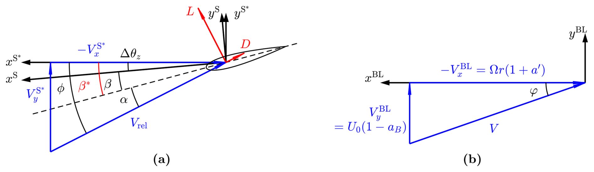
Figure 3Illustration of velocity triangles experienced by (a) the 2-D airfoil section and (b) the 3-D flow in the blade local coordinate system (BL-sys). In panel (a), the 2-D flow angle ϕ in S*-sys is shown. The airfoil is aligned along the dashed line. The twist angle is β in the S-sys and is β* in the S*-sys. The S-sys is rotated around its z axis by Δθz to get the S*-sys, with , which is the source of the difference between the two twist angles. The angle of attack α at the calculation point, which is the chord point as shown here, is also indicated. The 2-D lift and drag forces are applied perpendicularly and parallel to the 2-D relative velocity Vrel at the chord point, respectively. Panel (b) corresponds to the top view of a clockwise-rotating rotor with the blade pointing downward. The axial and tangential velocity components in BL-sys and the inflow angle φ are shown.
Figure 3 illustrates the relative velocity vector and its components as perceived by the blade section in the BL-sys and the 2-D airfoil in the S-sys and S*-sys. This visualization aids in understanding how velocity components differ between coordinate systems and highlights the impact on resulting flow angles.
The 2-D relative velocity is the velocity magnitude observed by the 2-D airfoil section, neglecting the spanwise velocity component that is normal to the airfoil.
The 2-D sectional flow angle ϕ in S*-sys is derived from Eq. (17).
The angle of attack at the calculation point is calculated from the 2-D flow angle ϕ and the twist angle β*, both defined in the S*-sys:
The 2-D sectional relative velocity magnitude Vrel in Eq. (18) is derived as a function of the 3-D relative velocity magnitude V.
The bound circulation vector of a blade section in BL-sys, labeled ΓBL, tangent to the blade's local main axis, is expressed as
For blades with prebend, the 2-D airfoil section experiences an effective torsional motion that result in aerodynamic forces and moments. This has been demonstrated in a previous study focusing on prebend-only blades (Li et al., 2022c). For a generalized curved blade, the angular velocity vector in S*-sys is first obtained. The effective torsion rate, labeled , is the z component of . A positive effective torsion rate corresponds to an effective nose-up motion of the airfoil section.2
The airfoil section of a blade with prebend also experiences an effective mid-chord heaving acceleration which also generates aerodynamic forces and moments (Li et al., 2022c). This effective mid-chord heaving acceleration, denoted , is obtained by projecting the centrifugal acceleration vector from the BL-sys onto the S*-sys. It is perpendicular to the chord line and is defined to be positive when pointing from the pressure side to the suction side.
2.3 Curved blade length correction
In aerodynamic load calculations using generalized lifting-line methods, which combine the 2-D airfoil modeling with the 3-D wake modeling, sectional loads are first obtained using 2-D airfoil polars. These loads are subsequently transformed into the 3-D blade or rotor coordinate system for further analysis. Alternatively, the lift force can be calculated from the bound circulation using the Kutta–Joukowski theorem in vector form through the cross-product operation, as discussed in Sect. 2.4. For both methods, the calculated loads correspond to load per unit span. This poses no issues when calculating the rotor-integrated loads if correctly integrating with respect to the span length. However, loads with other definitions, such as load per unit radius or load per unit of z coordinate in the blade root system (B-sys), are also commonly used for comparisons. Therefore, correction factors and are necessary to convert between different definitions and ensure consistent load comparisons. These correction factors can be derived by projecting the spanwise tangent vector in Eq. (1) onto the radial direction (zBL direction) or the zB direction using the dot product, as demonstrated in Madsen et al. (2020a). Alternatively, the correction factors can be directly obtained from the transformation matrices:
2.4 Kutta–Joukowski analysis
In this section, the lift force acting on the blade is calculated using the Kutta–Joukowski theorem in its vector form, applying the cross-product of the relative velocity vector and the bound circulation vector. This method directly provides the different components of the aerodynamic loads, eliminating the need for complex transformation matrices. The blade is modeled as a vortex filament aligned with the chord line of the blade, a framework commonly referred to as the lifting-line method. For each section, the lifting line is represented by the bound circulation vector, as in Eq. (22). The blade load due to lift force, represented as force per unit span, is expressed as
The local thrust and power coefficients from the Kutta–Joukowski analysis,3 which consider only the lift force, are calculated from the contributions of all NB blades for an annulus of the rotor disk at radius r:
where ks denotes the normalized circulation strength of all blades and λr denotes the local speed ratio at radius r:
For cases where the radial induction ur is neglected and assumed to be zero, as in standard BEM implementations, the coefficients in Eqs. (30) and (31) are simplified as follows. These simplified expressions correspond to the case of a straight blade without sweep or prebend, forming a planar rotor:
2.5 System closure and induction calculation
With a prescribed circulation distribution, calculating inductions using the BEM method with Prandtl's tip-loss correction (Glauert, 1935; Sørensen, 2015) included will still require an iterative process to solve for the inflow angle φ (Lønbæk et al., 2021). The blade's axial induction factor aB is calculated from the effective local thrust coefficient Ct,eff, which is adjusted by dividing it by the tip-loss factor F to account for the effects of having a finite number of blades, in contrast to the actuator disk concept used in the momentum theory of the BEM framework. The effective thrust coefficient Ct,eff is equal to the Kutta–Joukowski thrust coefficient Ct,KJ minus the contribution of wake rotation Ct,rot (Branlard and Gaunaa, 2015a). The wake rotation effect increases toward the rotor's rotational axis and decreases as the tip-speed ratio increases. In this study, the wake rotation effect is neglected, considering its impact is rather small for typical modern wind turbine designs, except in the root region, as demonstrated numerically in Branlard and Gaunaa (2015b). Including this effect would not change the study's conclusions, following the same arguments as previously presented in Sect. 3.2 of Li et al. (2022b).
The tip-loss factor F is calculated using the inflow angle φ, instead of the 2-D sectional flow angle ϕ that was used in the previous study (Li et al., 2022b). See Fig. 3 for an illustration of these angles. The tangential induction factor a′ is directly calculated from the circulation Γ, as in the vortex cylinder model (Øye, 1990; Branlard and Gaunaa, 2015b; Li et al., 2022b).
In the present work, the relationship between the axial induction factor and the thrust coefficient is computed using the empirical polynomial function in Eq. (39) proposed by Madsen et al. (2020a). This polynomial function is also the default relationship in the HAWC2 code (Larsen and Hansen, 2007).4
with coefficients k3=0.0883, k2=0.0586 and k1=0.2460.
By substituting Ct,KJ from Eq. (34) into Eq. (36), it becomes evident that the inductions are functions solely of the circulation distribution Γ or equivalently the Kutta–Joukowski thrust coefficient Ct,KJ. The inductions do not depend explicitly on the blade's dihedral angle κ or sweep angle ψ. Therefore, with the same prescribed circulation distribution, a curved blade will have the same inductions (aB and a′), inflow angle φ, and also Kutta–Joukowski thrust and power coefficients (Ct,KJ and Cp,KJ) as the corresponding straight blade forming a planar rotor.
This conclusion highlights that, within the BEM framework, the aerodynamic performance of a curved blade can be matched to that of a straight blade by ensuring that the circulation distribution is the same (Li et al., 2024). A more detailed proof is provided in Appendix B.
2.6 Relationship in chord and twist distributions
In this section, the relationship between the chord and twist distributions of a curved blade with a given main axis geometry and the corresponding straight blade that has the same bound circulation is derived under the BEM framework. The bound circulation strength is calculated from the 2-D relative velocity Vrel, the chord length and the 2-D lift coefficient obtained from airfoil polars.5 Following conclusions from unsteady 2-D airfoil theory, the magnitude of the lift coefficient is determined using the angle of attack evaluated at the chord point. Although it is not explicitly stated in the classical work by Theodorsen (1935), it can be inferred from the equations presented there. This is explicitly shown in the technical report by Øye (1981), as well as in later studies (Gaunaa, 2010; Bergami and Gaunaa, 2012; Li et al., 2022c).
As discussed in Sect. 2.2, when an airfoil section experiences an effective torsional rate , the sectional flow angle varies along the chord. For a rotor operating under steady-state conditions, this torsional rate is only from the projection of the angular velocity vector, as shown in Eq. (24). The difference in the angle of attack between the and chord points is given by
The angle of attack at the chord point can then be calculated from the 2-D flow angle ϕ (evaluated at the chord point), the twist angle β* and the additional angle Δα:
At each radial position, both curved and straight blades should operate with the same angle of attack at the chord point. They are also assumed to have the same spanwise distribution of relative thickness and airfoil series, enabling the use of the same airfoil polars. As a result, the lift coefficients of the two blades are also identical.
Substituting Eq. (44) into Eq. (40) gives the following relationship between the chord lengths:
As described in Sect. 2.5, the 3-D velocity magnitude V and the inflow angle φ at a given radius are the same for both the curved blade and its corresponding straight blade. For the straight blade, the 2-D relative velocity magnitude Vrel is equal to the 3-D value V and the 2-D flow angle ϕ is identical to the inflow angle φ.
For ease of derivation, denote the ratio of tangent and sine values of the 2-D sectional flow angle ϕ and the inflow angle φ as ζ and μ, respectively.
Substituting Eqs. (48) and (49) into Eqs. (19) and (21), respectively, the relationships in the 2-D flow angle and the relative velocity between curved and straight blades are derived to be
Inserting Eq. (51) into Eq. (45) gives the following relationship for the chord length:
Substituting Eqs. (24), (51) and (52) into Eq. (41), the difference in angle of attack between the and chord points due to the torsional rate for curved and straight blades is calculated as
Moreover, since the angle of attack at the chord point is identical for both curved and straight blades, the difference in twist angle in the modified sectional coordinate system (S*-sys) is calculated.
Since the twist angle is typically defined in the sectional coordinate system (S-sys), such as in the HAWC2 code (Larsen and Hansen, 2007),6 the twist angle difference in the S-sys is also derived:
where Δθz was given in Eq. (11).
2.6.1 Approximations and special conditions
To further illustrate the relationship between the chord and twist distributions of curved and straight blades, approximations are performed assuming the inflow angle φ is small. This condition is typically satisfied at high tip-speed ratios and near blade tip regions where the curved blade shapes are commonly employed.
The relationship between the curved and straight blades in terms of chord length in Eq. (52) and twist angle difference in Eq. (56) simplifies to
Two special conditions are investigated to highlight the impact of blade sweep and prebend on the modifications to the chord and twist distributions.
For the special condition that the blade has only sweep and no prebend (κ=0), it follows that , and the approximations are further simplified:
This shows that a swept blade requires a larger chord length and also a larger twist angle compared to the straight blade to maintain the same circulation distribution. The modifications in chord and twist distributions are symmetric: they depend only on the magnitude of the sweep angle, not on its sign.
For the special condition that the blade has only prebend and no sweep (ψ=0), it follows that ζ=cos κ, and the approximated relationships in chord and twist distributions can be simplified to
This suggests that a prebent blade has approximately the same chord length as the straight blade. The difference in twist angle has two components. The first part is due to the velocity projection, requiring the prebent blade to have a smaller twist angle. The second part is due to the torsional rate, resulting in a decreased twist angle for an upwind prebent blade (κ>0) and an increased twist angle for a downwind prebent blade (κ<0).
2.7 Local thrust and power coefficients
In the current BEM implementation, only the lift force is included in the iterative convergence calculations, which is the balancing of the momentum and angular momentum between the rotor and the flow. However, the drag force and the sectional moment also contribute to the aerodynamic loads on the blades, which are calculated in a post-processing step after the momentum balancing iteration has converged. First, the magnitudes of the lift, drag and sectional moment are calculated from the 2-D airfoil polars.7 The forces are then projected onto the blade local coordinate system (BL-sys). Detailed derivations can be found in Li et al. (2024).
The contributions of the drag force to the local thrust and power coefficients are as follows:
The sectional moment also contributes to the aerodynamic power coefficient as
where cstr is the chord length of the corresponding straight blade, as defined in Eq. (52).
2.7.1 Contribution of the non-circulatory force and moment
In previous work (Li et al., 2022c), it was shown that the airfoil sections of a prebent blade experience an effective torsional motion and an effective mid-chord heaving acceleration due to the projection of the angular velocity and the centrifugal acceleration, originating from the blade rotation. These effects will result in non-circulatory forces and moments, even when the rotor is operating under steady-state conditions. For blades with only prebend and no sweep, it was demonstrated that non-circulatory lift forces due to the effective torsion rate and the heaving acceleration approximately cancel each other out under steady-state conditions, resulting in negligible net contributions to thrust and power (Li et al., 2022c). However, the non-circulatory sectional moment and non-circulatory torsion rate drag force, which could also contribute to the aerodynamic power, were not considered significant in that analysis. In this study, non-circulatory forces and moments for generalized curved blades under steady-state conditions are derived. In addition, their contributions to the thrust and power coefficients are analyzed, with detailed derivations provided in Appendix C. Results show that, under steady-state operational conditions, the total contribution of non-circulatory loads to thrust and power is approximately zero. This also confirms that correctly implemented non-circulatory effects do not artificially enhance the rotor's performance or violate the Betz limit.
To validate this conclusion, numerical tests are performed using various curved blade configurations, including backward swept blades, upwind prebent blades and blades combining both backward sweep and upwind prebend. The blade planforms are presented in Sect. 4, and results are detailed in Appendix C.
These findings emphasize the importance of correctly including all non-circulatory terms in the 2-D unsteady aerodynamic model. Otherwise, an incomplete implementation with a net contribution from the non-circulatory loads under steady-state conditions could lead to incorrect results. Moreover, the non-circulatory forces and moments generally do not cancel out in unsteady conditions. As a result, a complete implementation is necessary to ensure accurate computation of flutter speeds and other aeroelastic properties.
2.7.2 Total local thrust and power coefficients
Combining the contributions from lift, drag and sectional moment, the total local thrust and power coefficients are derived. For the local thrust coefficient, the approximation can be made when the ratio of (also known as the glide ratio) is large and the inflow angle φ is small. This is typically satisfied for near-optimal operational conditions and near the blade tip.
For blades with only prebend and no sweep, the local thrust and power coefficients simplify as follows:
For blades with only sweep and no prebend, the local thrust and power coefficients are
For the special condition that the chord line of the blade is straight, the local thrust and power coefficients are in the same form as CLT and CLP derived by Lønbæk et al. (2021):
For cases where the lift coefficient is zero, such as in the root cylinder part of the blade, the above equations are not valid. In such cases, thrust and power coefficients should be derived using projections, resulting in different expressions. However, this special condition is of limited practical importance and is omitted for brevity.
2.8 Generalization: airfoil alignment and calculation point
In previous sections, the blade's main axis was defined as the chord line, with airfoils aligned perpendicularly to this axis. Calculation points were also placed along the chord line. These assumptions simplified the derivations and enabled direct load calculations from velocities in different coordinate systems using vector operations, as detailed in Sect. 2.4. This is because the lift force should be applied at the chord point, perpendicularly to the flow at this location (Bergami and Gaunaa, 2012; Pirrung and Gaunaa, 2018; Li et al., 2022c). However, practical implementations of the BEM method may use different definitions for the blade main axis and calculation points. For example, in the aeroelastic code HAWC2 (Larsen and Hansen, 2007), the main axis aligns along the chord line and the chord point serves as the calculation point.
In this section, the previous derivations are generalized to accommodate different definitions of the blade's main axis. The airfoils are still assumed to be aligned perpendicularly to the main axis, with the cross-flow principle (Hoerner and Borst, 1985) applied. In this generalized approach, the main axis is defined as the xma-chord line of the blade, which can vary along the span. For example, airfoils may align with the chord line in the blade root (cylinder) region and gradually transition to the chord line toward the blade tip. This flexible representation allows for a more general representation of the actual 3-D blade geometry. Additionally, the choice of the calculation point is also generalized. With a given blade planform, the choice of the calculation point should ideally not influence the final aerodynamic results.
2.8.1 Choice of calculation point
For blades with prebend or coning, the airfoil sections experience an effective torsional motion, as discussed in Sect. 2.2. This torsional motion causes the flow angle to vary along the chord. According to unsteady 2-D airfoil theory, flow information at two locations along the chord should be used: the lift force magnitude is determined using the flow condition at the chord point, while lift force should be applied at the chord point, perpendicularly to the flow at this location. To the best of the authors' knowledge, it was Øye (1981) who firstly explicitly demonstrated these aspects using unsteady 2-D airfoil theory, in a technical report written in Danish. These details are also explicitly presented in later works (Bergami and Gaunaa, 2012; Li et al., 2022c). In free-wake lifting-line (LL) methods, total velocities at both the and the chord points can be calculated directly (Li et al., 2022c). In the BEM method and other engineering aerodynamic models, however, a constant induced velocity for each blade section is typically assumed, with a single chordwise position (the xcp-chord point) chosen as the calculation point. The angles of attack at the and chord points can be approximated from the angle of attack at the calculation point (the xcp-chord point), using the effective torsion rate. Numerical studies with the LL method show that the magnitude of the 2-D relative velocity Vrel is nearly constant along the chord, even for blades with significant prebend and coning (Li et al., 2022c). Therefore, the angles of attack at different chordwise positions can be related as follows:
For a given blade planform, the total aerodynamic force and moment at the chord point should remain the same, irrespective of the choice of calculation point. Lift, drag and moment coefficients obtained from airfoil polars correspond to using the chord point as the calculation point. When a calculation point other than the chord point is used, adjustments are needed for the force and moment coefficients to ensure that the aerodynamic loads are correctly represented. These adjusted aerodynamic coefficients corresponding to the calculation point at the xcp-chord point are
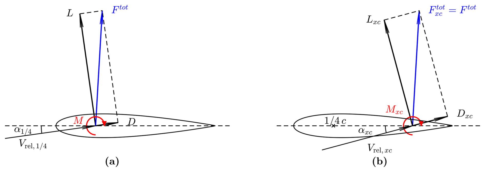
Figure 4Illustration of the projection of the aerodynamic force with respect to the flow direction at the chord point (a) and the xcp-chord point (b). The total sectional force Ftot on the airfoil remains the same. The sectional aerodynamic moment from the airfoil polars corresponds to the total sectional moment M evaluated at the chord point.
The compositions of the force and moment with the calculation point at the chord point and at the xcp-chord point are illustrated in Fig. 4.
2.8.2 Influence of airfoil alignment
In this section, different airfoil alignments are investigated. Since the choice of the calculation point does not affect the total aerodynamic loads, the calculation points (xcp-chord points) are assumed to coincide with the main axis (at the xma-chord line) for simplicity. Consequently, velocity vectors and flow angles derived in Sect. 2.2 correspond to the xcp-chord point rather than the chord point. The angles of attack at the and chord points are calculated from the angle at the xcp-chord point using Eqs. (75) and (76). Then, the 2-D force and moment coefficients corresponding to the xcp-chord point are calculated using Eqs. (77) to (79). Substituting these coefficients into Eqs. (67) and (68) provides the local thrust and power coefficients. This also implies that if the blade has prebend, the final equations for the local thrust and power coefficients will differ when the blades are aligned other than the chord line. Detailed derivations are omitted for brevity.
The relationships in chord and twist distributions derived in Sect. 2.6 with the main axis being the chord line are also generalized. As discussed in Sect. 2.8.1, the 2-D relative velocity magnitude Vrel is approximately constant along the chord. According to Eq. (45), the relationship in chord length between the curved blade and its corresponding straight blade is then identical to that derived in Sect. 2.6.
As shown in Eq. (75), the approximated angle of attack at the chord point is calculated from the 2-D flow angle ϕ (at the xcp-chord point), the twist angle β* in S*-sys and the additional angle due to the torsion rate :
where the additional angle is the difference between the angle of attack at the chord point and the xcp-chord point.
For curved and straight blades, the values of are derived from Eq. (75).
Since the value of is the same for both blades, the twist angle difference in the S*-sys is derived:
Furthermore, the twist angle difference in the S-sys can be calculated using Eq. (56). Assuming a small 2-D flow angle ϕ and inflow angle φ in Eq. (57), the twist angle difference is approximated as
For the special condition of a blade with only prebend, the twist angle difference is derived, differing from the case when using the chord line as the main axis:
In summary, when the airfoils are aligned differently than the chord line, the chord distribution relationship between curved and straight blades remains the same. However, the twist distribution relationship is affected by the choice of the airfoil alignment, particularly when the blade has prebend or coning. Prebent blades with the same main axis geometry, chord and twist distributions but different airfoil alignments (e.g., aligned to the chord line versus the chord line) will result in different angles of attack and thus different loads. This difference may become significant for blades with large prebend or coning, highlighting the importance of consistent airfoil alignment definitions in aerodynamic or aeroelastic analyses for prebent or coned blades.
2.9 Summary: modifying chord and twist to remove projection effects
This section summarizes the final equations for determining the chord and twist distributions of a curved blade within the BEM framework, ensuring the same bound circulation as that of a given straight baseline blade.
The approximations presented in Sect. 2.6.1, which assume a small inflow angle ϕ, are applied here. These approximations will be validated in Sect. 4 and shown to be sufficient. For reference, equations without these approximations are provided in Sect. 2.6 and 2.8, following similar calculation steps. The procedure for determining the chord and twist distributions of a curved blade, given its main axis geometry, consists of five steps:
-
Using the given chord and twist distributions of the baseline straight blade (cStr and βStr), solve for the converged induced velocities using the BEM method.
-
Compute the flow angles φ and ϕ, along with their tangent ratio ζ, using Eqs. (15), (19) and (48). Determine the 2-D relative velocity of the straight blade using Eq. (18).
-
Apply the approximation μ≈ζ and calculate the chord length and the 2-D relative velocity of the curved blade (ccur and ) using Eqs. (58) and (51).
-
Compute the effective torsion rate using Eq. (24), the change in angle of attack at the chord point using Eq. (81) and the additional twist angle Δθz using Eq. (11).
-
Finally, determine the twist angle βcur using Eq. (84).
In the present work, the high-fidelity Navier–Stokes solver EllipSys3D (Michelsen, 1992, 1994; Sørensen, 1995) and the low-fidelity BEM method are used for comparison. Key details regarding the model setups are provided below.
3.1 Reynolds-averaged Navier–Stokes (RANS) solver
The incompressible, pressure-based, three-dimensional solver EllipSys3D is used to solve the Reynolds-averaged Navier–Stokes (RANS) equations with finite volume discretization. The boundary conditions at the outer domain limit adopt an inlet/outlet strategy, and the k–ω SST (shear stress transport) model (Menter, 1994) is applied, assuming fully turbulent flow.
Rotor-resolved meshes are generated in two consecutive steps, fully scripted to maintain grid quality consistently. First, a structured surface mesh of the blade is generated using the PGLW tool (Zahle, 2019), with 128 spanwise and 256 chordwise cells. This surface mesh is then radially extruded into a volume grid using the hyperbolic mesh generator Hypgrid (Sørensen, 1998). A total of 256 cells are used in this process, and the resulting outer domain size is approximately 11 rotor diameters. Boundary layer clustering is applied, with an imposed first cell height of m, targeting y+ values below 1. The resulting volume meshes account for a total of 14.2 million cells. The grid topology of the baseline straight blade is detailed in Li et al. (2022b).
Although a steady solver is employed, the solver struggles to converge the solution as it gets stuck in limit cycles, particularly near the blade root and maximum chord where both the angle of attack and the airfoil's relative thickness are high. Unlike previous studies (Li et al., 2022b, d), which averaged CFD results over the last 350 iterations, the present work averages the last 50 iterations, resulting in increased load variation near the root. It is possible to apply convergence enhancement methods to the RANS CFD solver, such as the modified-BoostConv method (Dicholkar et al., 2022, 2024, 2025), to improve the convergence in the root region.
3.2 BEM method
The BEM method is used as the low-fidelity aerodynamic model, serving as the baseline for comparison. The BEM method implemented in the standalone BEVC code (Li et al., 2022b) is used, which is based on the HAWC2 aerodynamic module (Larsen and Hansen, 2007). The implementation uses a steady-state approach, meaning the polar-grid approach available in the HAWC2 code (Madsen et al., 2020a) for unsteady simulations or non-uniform inflow is not used. Detailed descriptions of the coordinate systems and projections of velocities and loads are discussed in Sect. 2. The unsteady 2-D aerodynamic model is also included, as the airfoil of prebent blades experiences effective torsional motion and heaving acceleration, even under steady-state operational conditions, as shown in Sect. 2.2. The complete implementation of the model is used, despite contributions due to non-circulatory forces and moments approximately canceling out, as discussed in Appendix C. As described in Sect. 2.7, only the lift force is used in the momentum balancing calculation. After the convergence is reached, the profile drag and the sectional moment are also included in the load calculation. The relationship between the axial induction factor and the thrust coefficient follows the polynomial relationship in Eq. (39) by Madsen et al. (2020a). Prandtl's tip-loss correction (Glauert, 1935; Sørensen, 2015) is applied to account for increased blade axial induction compared to the annulus-averaged value near the tip, due to the effect of the finite number of blades. The airfoil data used in the BEM method are from 2-D fully turbulent CFD simulations (Bortolotti et al., 2019), using EllipSys2D with the same turbulence model (k–ω SST) as employed in the 3-D CFD simulations described in Sect. 3.1. In previous benchmark studies (Barlas et al., 2022; Horcas et al., 2023; Zahle et al., 2024), BEM and other engineering aerodynamic models using the same 2-D airfoil data have shown good agreement with 3-D CFD results from EllipSys3D. This consistency provides a solid foundation for comparing BEM and CFD results in the present work. In the present study, each blade is radially discretized into 80 sections for the BEM calculation.
This section presents numerical results using both the BEM method and the high-fidelity RANS CFD solver (referred to as CFD). The primary objective is to numerically demonstrate that using the modified curved blades with adjusted chord and twist distributions leads to more consistent and meaningful comparisons than previous setups. This study revisits previous work on blades with only sweep (Li et al., 2022d) and only prebend (Li et al., 2022b) and extends the analysis to generalized curved blades combining both sweep and prebend.
4.1 Rotor configuration for comparison
The numerical tests use blades based on the IEA-10.0-198 10 MW reference wind turbine (RWT) (Bortolotti et al., 2019), consistent with previous studies (Li et al., 2022b, d). The main axis is defined as the half-chord line of the blade, and the airfoils are aligned perpendicularly to this main axis. The baseline straight blade is obtained by removing the prebend and sweep from the original RWT blade, resulting in a straight half-chord line. The blade length is 96.2 m with a hub radius of 2.8 m, giving a total rotor radius of 99 m. For all test cases, the rotor operates under steady-state conditions with a zero cone angle and uniform inflow perpendicularly to the rotor plane, implying no yaw error or rotor tilt. The blades are assumed to be rigid, excluding elastic deformation effects.
4.2 Operational conditions
The operational conditions used in this study align with those of previous work (Li et al., 2022b, d). Initially, an optimal operational condition with high rotor thrust is used for comparison. The rotors operate under a uniform inflow of 8 m s−1 with a constant rotational speed of 0.855 rad s−1 and zero blade pitch angle. For the rotor with baseline straight blades, the tip-speed ratio is 10.58, the rotor thrust coefficient is 0.90 and the rotor power coefficient is 0.46, as predicted by the BEM method. Additionally, comparisons are made under operational conditions corresponding to lower thrust coefficients. Three lower-loading operational conditions defined in the IEA Wind TCP Task 37 report (Bortolotti et al., 2019) are used, with a rotational speed of 0.909 rad s−1, wind speeds varying from 12.0 to 20.0 m s−1 and the blade pitched toward lower loadings. The operational conditions are summarized in Table 1, which also includes the rotor thrust and power coefficients predicted by the BEM method for the baseline straight blade. For brevity, the operational conditions are represented by the wind speeds in subsequent discussions.
Table 1Operational conditions used in the comparison. and are the thrust and power coefficients predicted by the BEM method for the baseline straight blade.
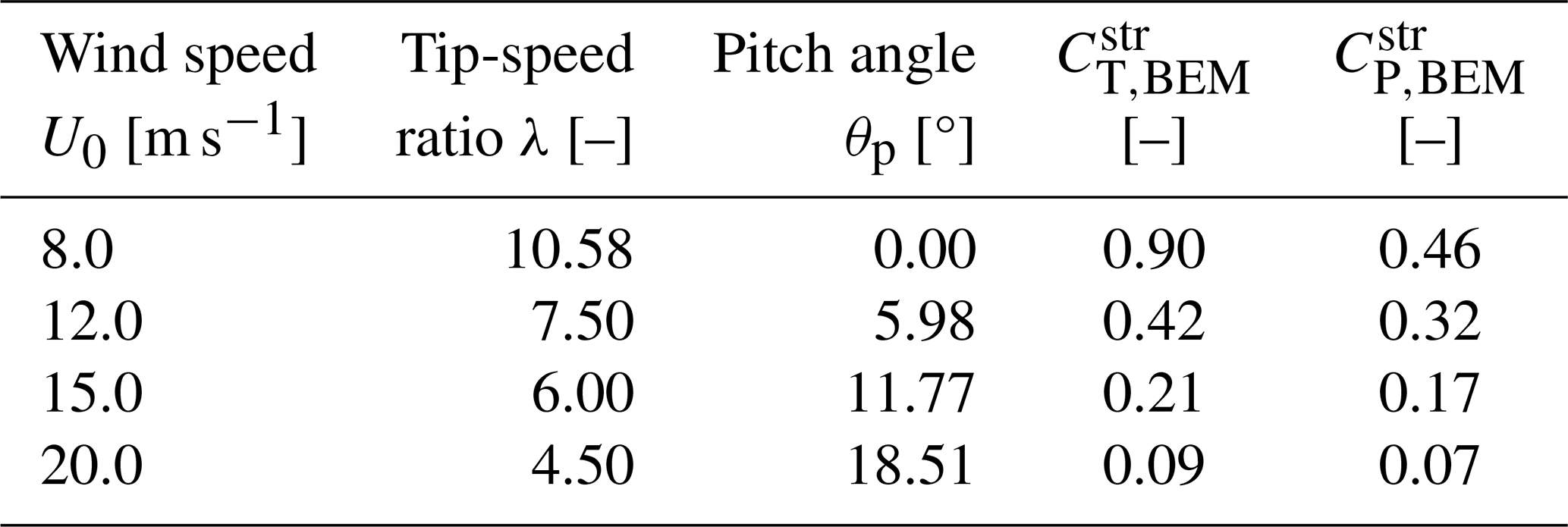
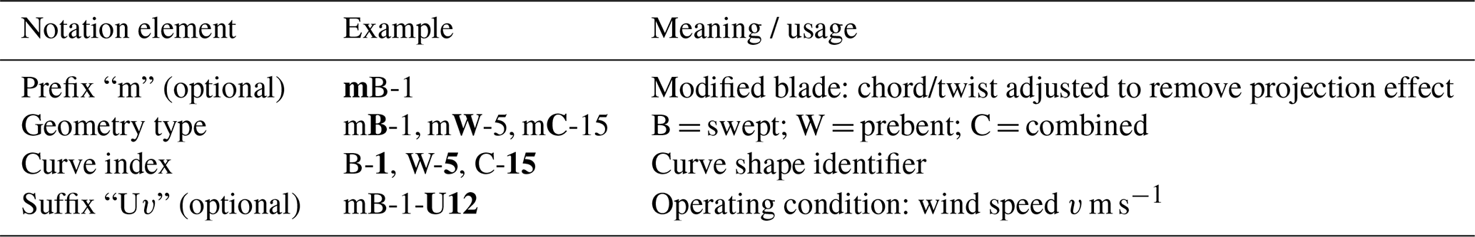
Table 2Naming convention for curved blades used in this study. The prefix and suffix are optional, depending on the blade type and operating condition. In each example, the relevant element is highlighted in bold for clarity.
4.3 Planform of curved blades
Two sets of curved blades are used for comparison: the original curved blades and the modified curved blades. The blade naming convention used to identify blade type, curve configuration and operating conditions throughout this study is summarized in Table 2. Further details for each blade type are provided in the following sections.
4.3.1 Original curved blades
The original curved blades follow the configurations used in previous studies (Li et al., 2022b, d), with the same chord and twist distributions as the baseline straight blade for blade sections with the same zB coordinates. The main axis geometries of these curved blades are modified from the baseline straight blade by adding xB components for blade sweep and by adding yB components for blade prebend, while the zB coordinates are kept unchanged. For blades with sweep (xB component), the radius will be increased compared to the baseline straight blade.
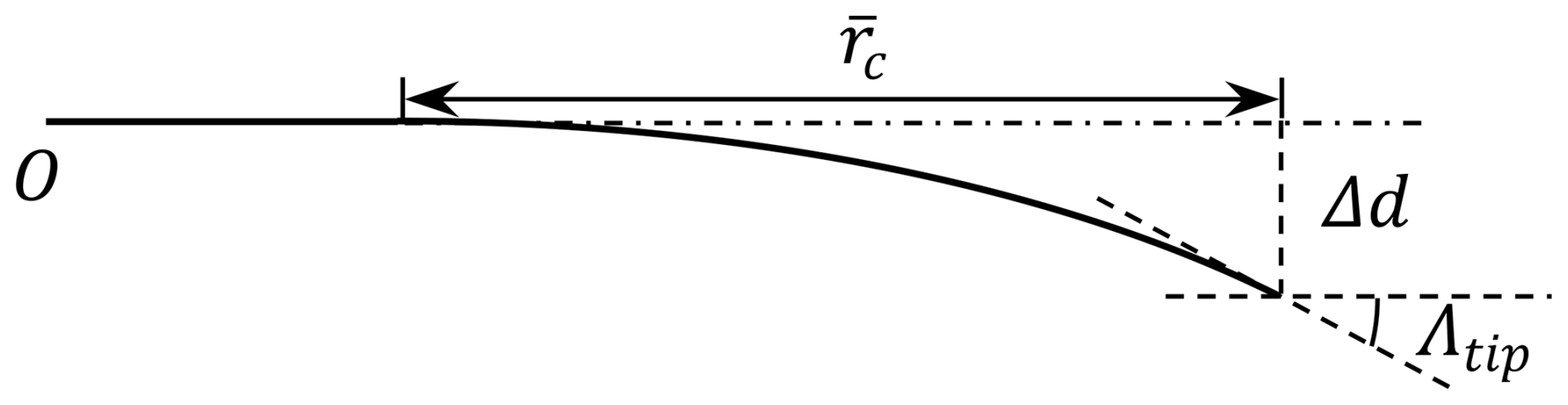
Following previous studies (Li et al., 2018, 2022b, d), the main axis geometry is defined using a modified Bézier curve parameterized by the curve ratio , the curve magnitude Δd and the tip curve angle Λtip, as illustrated in Fig. 5.
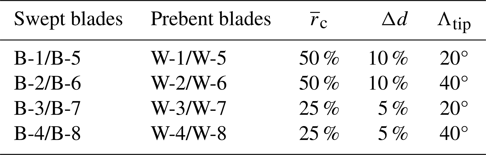
For the optimal operational condition at 8 m s−1 with high rotor loading and zero blade pitch, several blades have been used for comparison in previous studies. The study on swept blades (Li et al., 2022d) used four different backward swept blades, labeled Blade-1 to Blade-4. In addition, four forward swept blades, labeled Blade-5 to Blade-8, with the same curve parameters as Blade-1 to Blade-4 but opposite sweep directions, were also introduced. These swept blades with different sweep magnitudes and tip sweep angles were introduced to represent different possible swept blade shapes. In the present work, they are abbreviated as B-1 to B-8 and referred to as the original swept blades. In the previous study on prebent blades (Li et al., 2022b), the main axis geometries of the prebent blades (labeled W-1 to W-8) are identical to the swept blades (B-1 to B-8) but with the curvature applied in the prebend direction (yB direction) instead of sweep (xB direction). The original prebent blades W-1 to W-4 feature upwind prebend, and W-5 to W-8 feature downwind prebend. The parameters of these curved blades are summarized in Table 3.
Table 3Parameters of the planforms of the curved blades. Only the first set of curved blades is used for comparison in the present study.
In this study, the focus is on the first set of curved blades: swept blades B-1 and B-5 and prebent blades W-1 and W-5. The front view of the swept blades B-1 and B-5 is illustrated in Fig. 6. The top view of the prebent blades W-1 and W-5 is shown in Fig. 7.
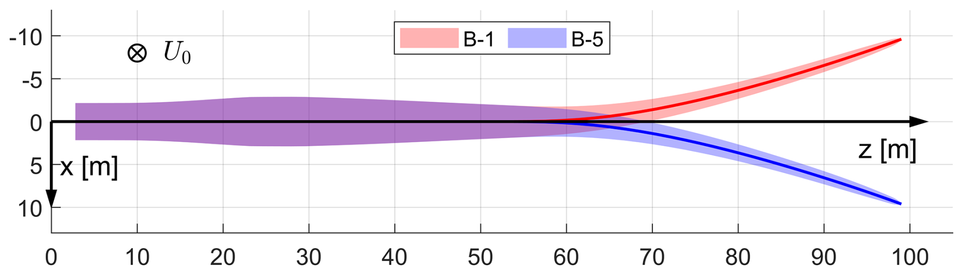
Figure 6Front view of the backward swept blade B-1 and forward swept blade B-5, with main axes highlighted, in the blade root coordinate system (B-sys). This corresponds to the front view of the rotor with the blade pointing east. The free-stream wind velocity vector is also shown.
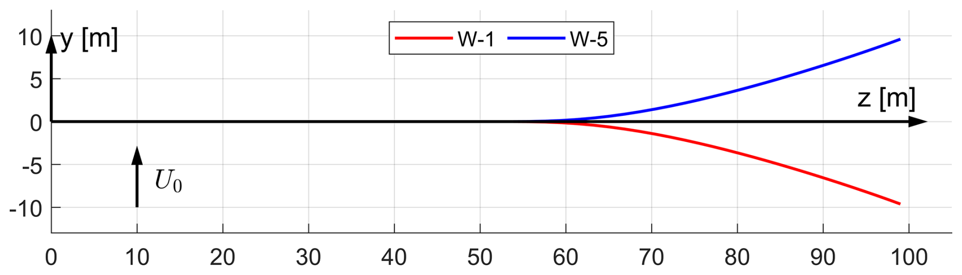
Figure 7Top view of the main axis geometries of upwind prebent blade W-1 and downwind prebent blade W-5, in the blade root coordinate system (B-sys). This corresponds to the top view of the rotor with the blade pointing east. The free-stream wind velocity vector is also shown.
It has been tested that other swept and prebent blades with different main-axis curved shapes exhibit similar behaviors to the curved blades used in the present work. Including these additional results will not change the conclusions of the present work. The results of other swept and prebent blades are summarized in an internet appendix (Li et al., 2025).
For operational conditions corresponding to lower thrust coefficients in Table 1, blade pitching effects are introduced as an additional constant twist angle offset, rather than a rotation around the pitch axis (zB axis). This approach maintains the blade's 3-D main axis coordinates in B-sys. For these lower-loading cases, the original swept blades based on B-b are labeled B-b-Uv, where b is the swept blade index and v is the wind speed in m s−1. Similarly, the original prebent blades based on W-w are labeled W-w-Uv, where w is the prebent blade index.
4.3.2 Modified curved blades
The modified curved blades have their chord and twist distributions adjusted based on the original curved blades, following the relationships derived in Sect. 2.6. These modifications ensure that the BEM method predicts these modified curved blades to have the same circulation distribution as the corresponding baseline straight blades. Further, the loads due to the lift force will also be identical between the curved and straight blade; only negligible differences due to the drag force remain. These modified blades are expected to allow for consistent comparisons by subtracting the projection effects, thereby highlighting the effects of wake geometry on inductions and resulting loads. Since the main axis is defined along the half-chord line, the generalized chord and twist distribution relationships derived in Sect. 2.8 with xcp=0.5 are applied. The approximations presented in Sect. 2.8.2 are used, which will be shown to be sufficient for this study.
For the swept blades, two modifications are applied to the original swept blades. First, the main axis geometries are scaled such that each blade section has the same radius as the corresponding section of the baseline straight blade. Second, the chord lengths and twist angles are modified according to Eqs. (60) and (61). Specifically, both the chord length and the twist angle are increased. The original swept blades B-b are modified to mB-b, and the original swept blades B-b-Uv for lower-loading conditions are modified to mB-b-Uv.
For the prebent blades, since the radii are already identical to the baseline straight blade, scaling of the main axis geometry as done for the swept cases is not necessary. Using the approximated relationship in Sect. 2.8.2, the chord distribution remains unchanged from the original prebent blades. However, the twist angles are adjusted according to Eq. (85), with the condition of xcp=0.5 for the current setup. The original prebent blades W-w are modified to mW-w, and the original prebent blades W-w-Uv for lower-loading conditions are modified to mW-w-Uv.
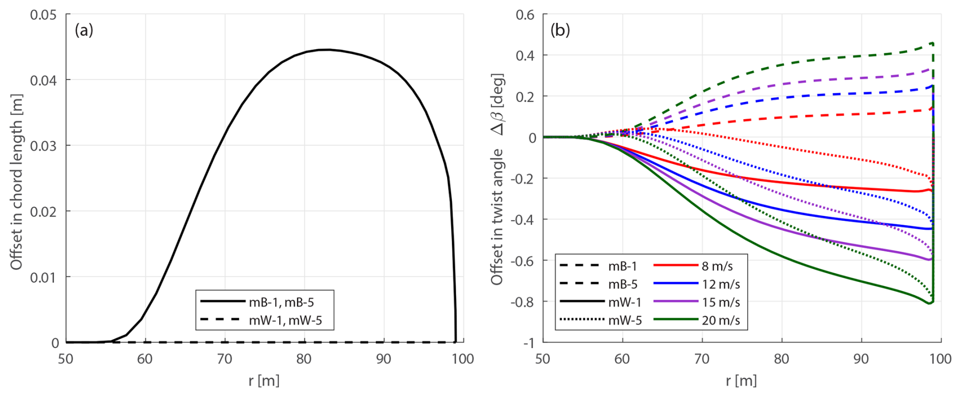
Figure 8Offset in chord length (a) and twist angle Δβ (b) of modified swept blades mB-1 and mB-5, as well as modified prebent blades mW-1 and mW-5 compared to the baseline straight blade. The swept blades mB-1 and mB-5 have identical chord and twist distributions for different wind speeds.
Figure 8 illustrates the planform modifications applied to the swept and prebent blades in terms of chord length and twist angle. Only the outboard region of the blade (from a radius of 50 m to the blade tip) is shown, as the chord and twist remain unchanged in the straight inboard portion of the blade. Panel (a) shows the chord length offset relative to the baseline straight blade.8 For the modified swept blades (mB-1 and mB-5), the chord length is increased in the swept region, consistent with Eq. (60). In contrast, the modified prebent blades (mW-1 and mW-5) have the same chord distribution as the baseline straight blade, in agreement with Eq. (62). As also indicated in the figure, the chord length does not change with wind speed, which is as expected. Panel (b) presents the twist angle offset Δβ for the modified swept and prebent blades across different wind speeds. The modified swept blades consistently show an increased twist angle, while the modified prebent blades generally show a reduced twist. An exception occurs under the optimal condition of 8 m s−1, where the modified upwind prebent blade mW-1 shows a slight increase in twist in the mid-span region due to the torsional rate term. The overall magnitude of the twist angle offset Δβ increases with wind speed, consistent with the corresponding increase in flow angle ϕ. Overall, the trends of the twist angle offsets observed in panel (b) are consistent with the formulations provided in Eqs. (61) and (85).
In comparison, Gözcü and Verelst (2020) reported the blade tip torsional deformations between 1.0 and 2.3° in aeroelastic simulations of the IEA 10 MW RWT blade for the operational conditions used in the present work. Therefore, the twist modifications applied here are, on average, approximately 5 times smaller than the aeroelastic torsional deformations.
4.3.3 Blades with sweep and prebend combined
Curved blades combining both sweep and prebend are also introduced to investigate generalized curved blade configurations. First, curved blades that are generated using similar ideas to those behind the original swept and prebent blades described in Sect. 4.3.1 are referred to as the original curved blades. The main axis geometry of the original curved blade is adjusted from the baseline straight blade: the xB and yB coordinates are adjusted to allow sweep and prebend, while the zB coordinate remains unchanged. The chord, twist and relative thickness distributions remain the same as the baseline blade for blade sections with the same zB coordinates. In the present work, the original curved blades are generated by superimposing the main axis geometries of the original swept blades and the original prebent blades. These original combined curved blades are labeled C-bw, where b and w are the indices of the corresponding original swept blade B-b and prebent blade W-w. Four cases are used for comparison in this study, which are C-11, C-55, C-15 and C-51, representing combinations of the swept blades B-1 and B-5 and the prebent blades W-1 and W-5. Specifically, blade C-11 has backward sweep and upwind prebend, blade C-55 has forward sweep and downwind prebend, blade C-15 has backward sweep and downwind prebend, and blade C-51 has forward sweep and upwind prebend.
These four cases are representative, covering all possible combinations of sweep and prebend directions. Furthermore, they correspond to different combinations of load redistribution effects observed in previous studies (Li et al., 2022b, d). For example, the influences of backward sweep and upwind prebend have similar patterns for the spanwise load redistribution, which are in opposite directions to the influence due to forward sweep and downwind prebend. Consequently, the influence of wake geometry on loads is expected to be more pronounced for blades C-11 and C-55 due to the expected superpositioning of load redistribution effects. In contrast, for blades C-15 and C-51, the influence of wake geometry on loads is expected to be weaker, since the sweep and prebend effects oppose each other and are expected to partially cancel out.
The original curved blades are modified to the modified curved blades for a consistent comparison, where two modifications are necessary. First, the main axis geometry is scaled to match the radius of each section of the baseline straight blade. Second, the chord and twist distributions are adjusted according to Eqs. (52) and (83), with the condition xcp=0.5 applied. The original curved blades C-bw are modified to mC-bw, and the original curved blades C-bw-Uv for lower-loading conditions are modified to mC-bw-Uv.
It has been tested that other combined curved blades with different main-axis curved shapes exhibit similar behaviors to the curved blades used in the present work. Their results are summarized in an internet appendix (Li et al., 2025).
4.4 Loads for comparison
In previous studies (Li et al., 2022b, d), aerodynamic loads were directly presented and compared using dimensioned values. In the present work, non-dimensional loads are used to provide a clearer representation of the relative changes between curved and straight blades. Different non-dimensional load definitions are used for the original and modified setups to ensure meaningful comparisons. This distinction is made because, in the original setup, the zB-coordinate length is fixed at 99 m, while in the modified setup, the radius9 is fixed at 99 m. Additionally, in previous studies involving blades with only sweep or prebend, the original setup used loads in the yB and xB directions for comparison. For the modified setup, however, loads in the yBL and xBL directions are more physically meaningful, since the xBL direction aligns with the tangential direction.
4.4.1 Comparison for original curved blades
In previous work on swept blades (Li et al., 2022d), loads in the yB and xB directions in the blade root coordinate system (B-sys) were referred to as the out-of-plane and in-plane loads, respectively. In the present work, they are non-dimensionalized into a local thrust coefficient and a simplified local power coefficient, defined as
Here, the simplified local power coefficient represents the contribution of the in-plane force to the power, acknowledging that the in-plane force is not perpendicular to the radial direction and that other loads also contribute to the power.
To highlight differences between the curved and straight blades, offsets in the non-dimensional loads are used for comparison. These offsets are the difference in loads between the original curved blade and the baseline straight blade, evaluated at the same zB coordinate:
As shown by Lønbæk et al. (2021), the rotor-integrated thrust and simplified power coefficients can be calculated from the local thrust and simplified power coefficients.
4.4.2 Comparison for modified curved blades
In the present work, the axial and tangential loads are defined as the loads in the yBL and xBL directions in the blade local coordinate system (BL-sys). With this definition, the axial load is normal to the rotor plane and the tangential load is perpendicular to the radial direction at each blade section. These loads are non-dimensionalized into the local thrust coefficient and a simplified local power coefficient:
The simplified power coefficient in Eq. (93) represents the contribution of the tangential force to power. Note that other loads, such as sectional moments, also contribute to aerodynamic power. In the following sections, the local thrust coefficient and the simplified local power coefficient are referred to as the thrust coefficient and power coefficient for brevity.
While the thrust coefficients in Eqs. (86) and (92) can be directly compared, the simplified power coefficients in Eqs. (87) and (93) correspond to loads in slightly different directions. For blades without sweep, where the main axis has no xB component, the blade root coordinate system (B-sys) will coincide with the blade local coordinate system (BL-sys). In this case, Eqs. (86) and (87) will be identical to Eqs. (92) and (93).
To highlight the influence of curved blade geometry on the loads, the offsets of the non-dimensional loads are used for comparison. They are the load differences between the modified curved blade and the baseline straight blade at the same radial positions:
For the modified curved blades, the rotor-integrated thrust and simplified power coefficients are calculated as
4.4.3 Subtracting the projection effects in CFD results using the BEM method
This section introduces a method to adjust the CFD results of the original curved blades by subtracting the projection effects estimated using the BEM method. For the original curved blade, which has the same chord and twist distributions as the baseline straight blade, the CFD results include contributions from both projection and wake-induced effects. In contrast, the BEM results should only have the influence due to projections. Thus, the difference in loads between the original curved blade and the corresponding modified curved blade in the BEM results provides an estimation of the projection effects. Subsequently, the CFD results of the original curved blades can be adjusted by subtracting the estimated projection effects:
Since the modified curved blade has the same radius as the baseline straight blade, while the original curved blade has the same zB coordinate as the baseline, the subtraction is conducted for the corresponding abscissas.
The adjusted CFD results of the original curved blades are expected to closely match the CFD results of the modified curved blades, effectively isolating the wake-induced effects for a more consistent comparison.
4.5 Baseline straight blade
Before comparing the curved blades, the thrust and power coefficients of the baseline straight blade operating at 8 m s−1 predicted by the BEM method and the CFD solver are firstly shown in Fig. 9. These results correspond to Eqs. (86) and (87) or Eqs. (92) and (93), as the blade root coordinate system (B-sys) and the blade local coordinate system (BL-sys) coincide for the straight blade configuration.
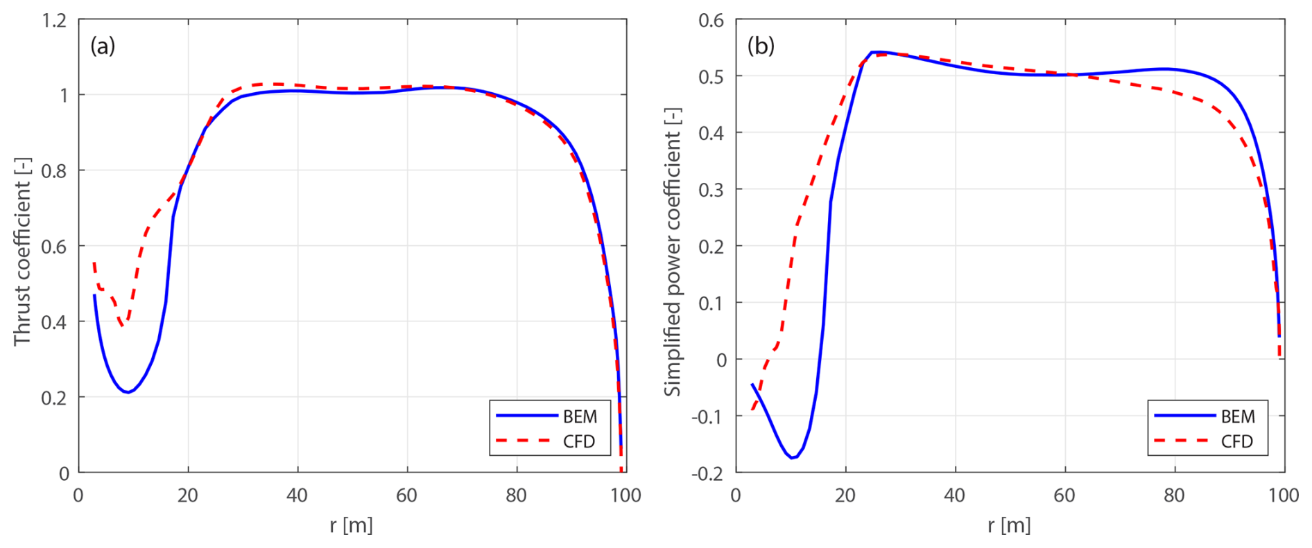
Figure 9Thrust coefficient Ct (a) and simplified power coefficient (b) of the baseline straight blade, calculated using the BEM method and the CFD solver, at a wind speed of 8 m s−1.
In the blade root region, the difference is relatively large for loads in both directions, primarily due to unsteady flow separation effects in this region. Therefore, the focus of the comparison is on the region from a radius of 20 m to the blade tip.
For the thrust coefficient, the BEM and CFD predictions are in close agreement. According to the Kutta–Joukowski analysis presented in Sect. 2.4, the similarity in thrust indicates that the bound circulation distributions predicted by both methods are very similar. However, discrepancies are observed in the power coefficient, where the BEM method tends to over-predict the tangential loads, especially from a radius of 60 m to the blade tip. This discrepancy is likely related to the empirical nature of the tip loss and high-thrust corrections implemented in the BEM method. Specifically, the BEM method relies on the empirical Prandtl's tip-loss correction that does not account for wake expansion and wake roll-up, which can significantly influence tip flow behavior under high-loading conditions. Similarly, the empirical polynomial a–Ct relationship is used under this high-thrust condition. In contrast, the CFD solver is modeling the tip effects with much higher fidelity, since the flow around the 3-D blade geometry is fully resolved and does not require an empirical high-thrust correction.
For operational conditions with higher wind speeds and lower thrust coefficients, as listed in Table 1, the results are presented in Appendix D1. As the wind speed increases and the rotor loading decreases, the agreement between the BEM and CFD results generally improves for both thrust and power coefficients. This improvement is due to the reduced induction effects and lower uncertainty in the a–Ct relationship in the lower-thrust region.
4.6 Blades with only sweep
This section examines blades with only sweep and no prebend, revisiting the previous study presented in Li et al. (2022d). In that work, comparisons were made using various aerodynamic models, including the BEM method, the CFD solver, the lifting-line method and a mid-fidelity engineering model developed in that study to improve swept blade modeling. The comparisons were conducted using the original swept blades, which have the same chord and twist distributions as the baseline straight blade. The primary objectives were to investigate the impact of blade sweep on wake geometry and the consequent effects on loads and to demonstrate the improved agreement of the new model with CFD and lifting-line methods in modeling blade sweep effects. In the present work, results from both the original and the modified swept blades are used for the comparison.
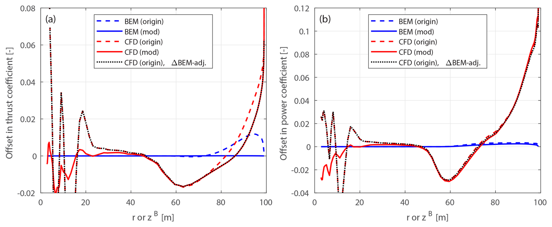
Figure 10Offset in thrust coefficient ΔCt (a) and simplified power coefficients and (b) of the original backward swept blade B-1 and the modified backward swept blade mB-1, compared to the baseline straight blade, at a wind speed of 8 m s−1.
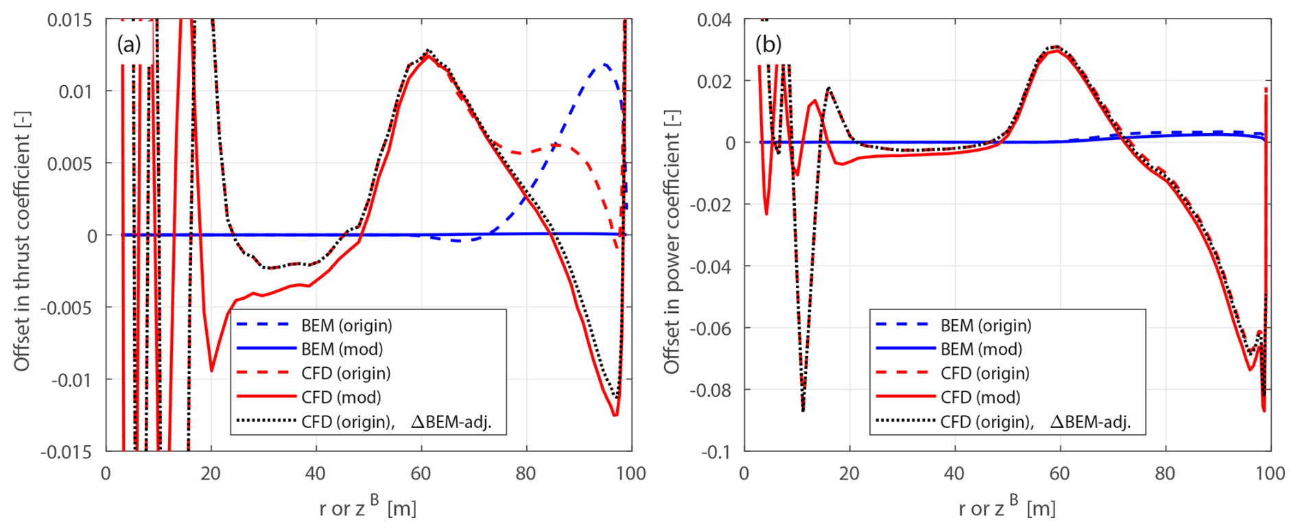
Figure 11Offset in thrust coefficient ΔCt (a) and simplified power coefficients and (b) of the original forward swept blade B-5 and the modified forward swept blade mB-5, compared to the baseline straight blade, at a wind speed of 8 m s−1.
4.6.1 Optimal operational condition
The optimal operational condition with a uniform inflow velocity of 8 m s−1 is firstly used for comparison. The offsets in thrust and power coefficients for both the original and the modified swept blades, compared to the baseline straight blade, are plotted in Figs. 10 and 11. For the original swept blades B-1 and B-5, the load offsets ΔCt and are calculated using Eqs. (88) and (89) and plotted against the zB coordinates. For the modified swept blades mB-1 and mB-5, the load offsets ΔCt and are calculated using Eqs. (94) and (95) and plotted against the radius. In addition, the adjusted CFD results of the original swept blades, obtained by subtracting the BEM thrust and power differences between original and modified blades, Eqs. (98) and (99), are included for comparison.
For the original swept blades, the load offsets predicted by the BEM method are due to the projection effects. Specifically, the thrust coefficient offsets for B-1 and B-5 predicted by the BEM method show a small increase, both reaching a maximum magnitude of only approximately 0.01 at the zB coordinate of 94 m. The power coefficient offsets predicted by the BEM method are approximately zero. This suggests that the projection effects are small for these original swept blades, indicating that they operate under similar conditions to the baseline straight blade. For the modified swept blades mB-1 and mB-5, the offsets in both thrust and power coefficients predicted by the BEM method are approximately zero throughout the span, confirming that the projection effects are effectively subtracted. This validates the modifications to the chord and twist distributions derived in Sect. 2.6.1 as well as the approximations made in Sect. 2.8.2.
The CFD results include the impact of changed wake geometries on the aerodynamics, as evidenced by the larger load offsets between the modified swept blades (mB-1 and mB-5) and the baseline straight blade. For the inboard part of the swept blade (radius less than 50 m), where the main axis is still straight, the loads are approximately identical to those of the baseline straight blade. In the swept part of the blade (radius greater than 50 m), a distinctive spanwise load redistribution pattern is observed. For the backward swept blade mB-1, when moving toward the blade tip, the load is initially lower compared to the baseline straight blade until approximately halfway toward the blade tip (radius of 80 m). Subsequently, when moving further toward the tip, the load increases and becomes higher compared to the baseline straight blade until the blade tip. For the forward swept blade mB-5, an opposite load redistribution pattern is observed. These load redistribution patterns for the swept blades are consistent with observations from previous studies (Li et al., 2020, 2022d). For the swept blades, both projection and wake-induced effects are concentrated in the outboard half of the span. This is because for the swept blades used in this study, the blade sweep begins only from the mid-span, and the inboard section remains straight.
The performance of using the CFD results of the original swept blades (B-1 and B-5) to investigate the wake-induced effects of the swept blade, as has been done in previous work (Li et al., 2022d), is also analyzed. As shown in Figs. 10 and 11, the power coefficient offsets are almost identical between the original and modified setups. For the thrust coefficient, the offsets are slightly increased for both original swept blades due to projection effects. For the original backward swept blade B-1, a load redistribution pattern is still observed, although it is slightly altered by the projection effects. In contrast, for the original forward swept blade B-5, the load redistribution effect in the thrust coefficient is not observed. Instead, the thrust coefficient is consistently increased from a radius of 50 m to the blade tip. The CFD results of the original swept blades adjusted using BEM results according to Eqs. (98) and (99), labeled “CFD (origin), ΔBEM-adj.” in Figs. 10 and 11, show good agreement with the CFD results of the modified swept blades. This indicates that the projection effects in the CFD and BEM results are similar for swept blades and can be effectively subtracted using this adjustment.10
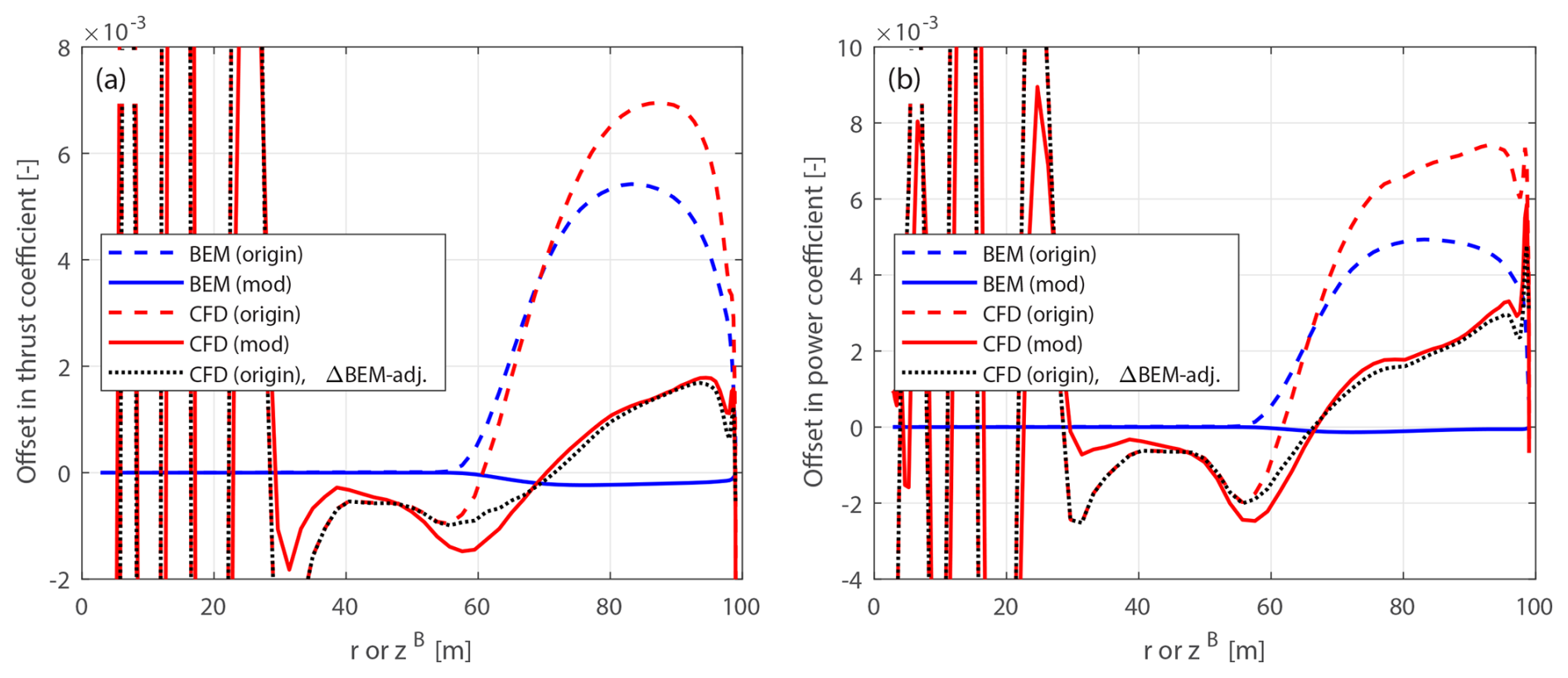
Figure 12Offset in thrust coefficient ΔCt (a) and simplified power coefficients and (b) of the original and modified backward swept blades B-1-U20 and mB-1-U20 compared to the baseline straight blade, at a wind speed of 20 m s−1.
4.6.2 Lower-loading conditions
In the previous work (Li et al., 2022d), only the optimal operational condition at 8 m s−1 was considered. This study extends the analysis to lower-loading conditions, as listed in Table 1. Results for the backward swept blades B-1-Uv and mB-1-Uv at a wind speed of 20 m s−1 (lowest-loading condition) are presented in Fig. 12, while results under intermediate conditions (12 and 15 m s−1) are presented in Fig. D2 in Appendix D2.11 Similar conclusions apply to the forward swept blades B-5-Uv and mB-5-Uv, which are therefore not shown in this study.
For the modified swept blades under all tested lower-loading conditions (12, 15 and 20 m s−1), the offsets in thrust and power coefficients predicted by the BEM method are approximately zero, indicating negligible projection effects. For these lower-loading conditions, the CFD results of the modified swept blades show clear load redistribution patterns, similar to those observed under the optimal condition. This suggests that the wake-induced effects due to blade sweep geometry maintain similar patterns across both high- and low-loading conditions. As wind speed increases and rotor loading decreases, the wake-induced effects gradually diminish, while the projection effects become more pronounced. This trend is particularly evident from the CFD results at the highest wind speed (20 m s−1): the load offset of the modified swept blade is significantly smaller compared to that of the original swept blade, especially for the local thrust coefficient.
Thus, the CFD results of the original swept blades are insufficient to correctly draw conclusions on the wake-induced effects of swept blades for low-loading conditions. Specifically, the local thrust and power coefficients near the blade tip are substantially overestimated at a wind speed of 20 m s−1 due to strong projection effects. Once again, the adjusted CFD results of the original swept blades, using BEM-based corrections in Eqs. (98) and (99), show good agreement with the CFD results of the modified swept blades under all tested lower-loading conditions. This demonstrates that the projection effects of swept blades can be effectively subtracted using this adjustment method, even under lower-loading conditions.
4.6.3 Rotor-integrated effects
In this section, CFD results are used to provide a clear overview of the individual and combined influences of projection and wake-induced effects on rotor-integrated thrust and simplified power coefficients. First, the wake-induced effect is calculated from the CFD results of the modified curved blades:
where Ci is either the thrust coefficient (CT) in Eq. (96) or the simplified power coefficient () in Eq. (97).
Second, the total effect (combined projection and wake-induced effects) is calculated from the CFD results of the original curved blades:
where Ci is either the thrust coefficient (CT) in Eq. (90) or the simplified power coefficient () in Eq. (91).
Finally, the projection effect is determined by subtracting the wake-induced effect from the total effect:
Table 4Relative differences (in %) in rotor-integrated thrust and power coefficients due to projection, wake-induced and total effects for the backward swept blade B-1, as calculated from the CFD solver under different operational conditions.
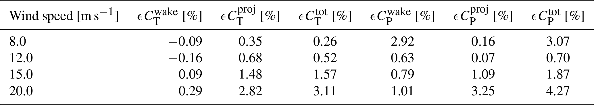
Table 4 summarizes these contributions for the backward swept blade B-1 across different operational conditions.
Under the optimal operating condition, the influence of blade sweep on the rotor-integrated power is dominated by the wake-induced effect, with minimal contribution from the projection effect. However, for the rotor-integrated thrust, the projection effect is more than 3 times as large as the wake-induced effect. This is because the spanwise load redistribution is partially canceled out when integrating along the blade span. As wind speed increases and rotor loading decreases, the projection effect becomes increasingly dominant over the wake-induced effect, for both rotor-integrated thrust and power. For example, at a wind speed of 20 m s−1, the projection effect is approximately 9 times as large as the wake-induced effect for thrust and about 3 times as large for power.
4.6.4 Summary
In summary, the original swept blade setup in the previous work (Li et al., 2022d) is sufficient to show the wake-induced effects of swept blades under the optimal operational condition with high rotor loadings. However, for conditions with higher wind speeds and lower rotor thrust coefficients that were not presented in that previous work (Li et al., 2022d), the wake-induced effects decrease while projection effects become dominant. This trend is consistent for both load distributions along the blade span and the rotor-integrated loads. Hence, the original swept blades are insufficient to correctly draw conclusions under these lower-loading conditions. In comparison, the modified swept blades provide a consistent basis for comparison across all tested operational conditions. With the modified swept blades, the impact of wake geometry on the load is isolated and can be directly visualized from the CFD results. Additionally, it is demonstrated that the projection effects in the CFD results of the original swept blades can be effectively subtracted using BEM-based adjustments.
4.7 Blades with only prebend
This section examines blades with only prebend and no sweep, revisiting the previous study presented in Li et al. (2022b). In that work, comparisons were performed using the BEM method, the lifting-line method, and the CFD solver and a mid-fidelity engineering aerodynamic model developed within that study to improve prebent blade modeling. The comparisons were conducted using the original prebent blades, which have both projection and wake-induced effects included. The primary objectives were to investigate the impact of blade prebend on wake geometry and the resulting effects on loads and to demonstrate the improved agreement between the higher-fidelity LL and CFD solvers and the newly developed model compared to the BEM method in predicting the prebend effects. In the present work, results from both the original and the modified prebent blades are used for the comparison.
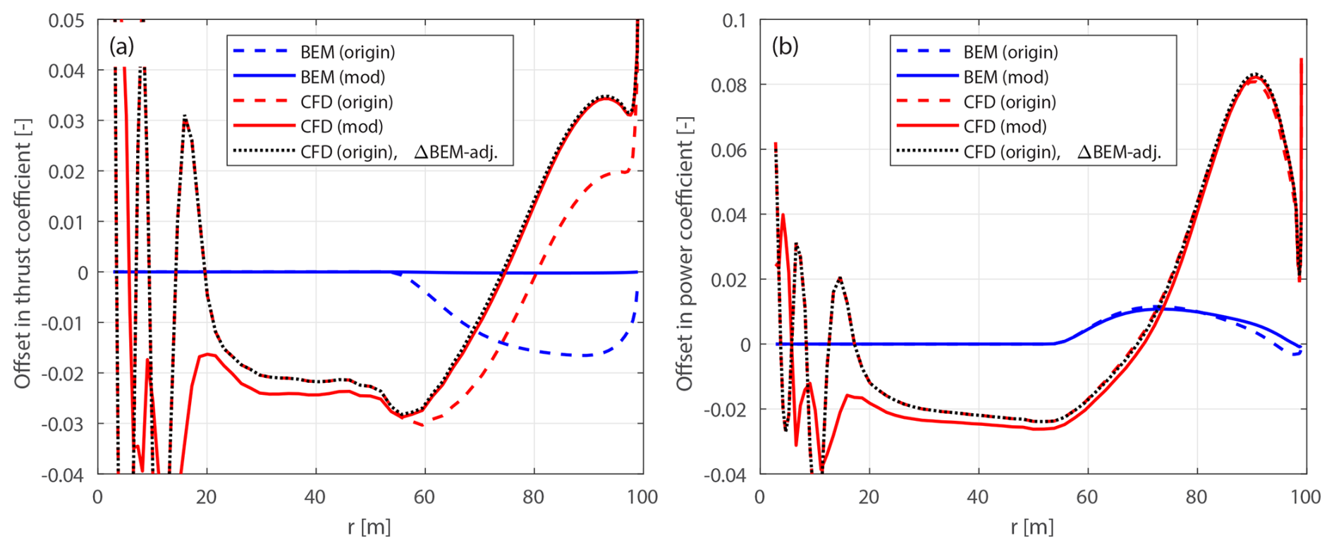
Figure 13Offset in thrust coefficient ΔCt (a) and simplified power coefficient (b) of the original upwind prebent blade W-1 and the modified upwind prebent blade mW-1, compared to the baseline straight blade, at a wind speed of 8 m s−1.
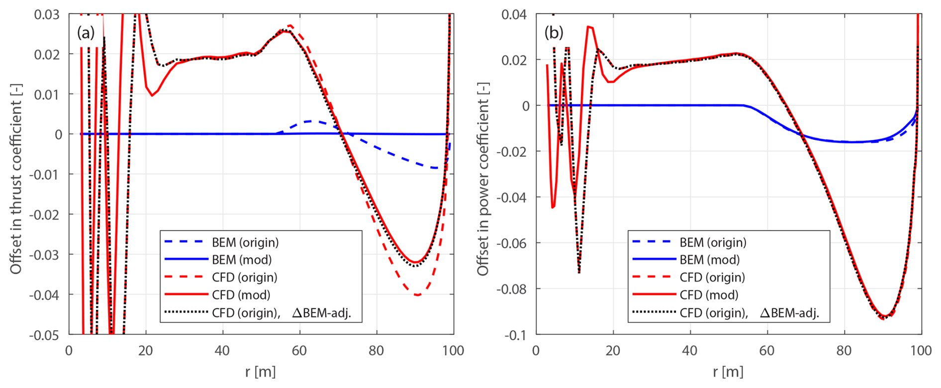
Figure 14Offset in thrust coefficient ΔCt (a) and simplified power coefficient (b) of the original downwind prebent blade W-5 and the modified downwind prebent blade mW-5, compared to the baseline straight blade, at a wind speed of 8 m s−1.
4.7.1 Optimal operation condition
The optimal operational condition with a uniform inflow velocity of 8 m s−1 is first used for comparison. The load offsets of the original and modified prebent blades compared to the baseline straight blade are calculated using Eqs. (94) and (95) and are plotted against the radius. Since B-sys coincides with BL-sys for blades without sweep, the thrust coefficients Ct(r) and Ct(zB) in Eqs. (88) and (94) and the simplified power coefficients and in Eqs. (89) and (95) are identical. Results of the original and modified upwind prebent blades (W-1 and mW-1) are shown in Fig. 13. Results of the downwind prebent blades (W-5 and mW-5) are shown in Fig. 14. In addition, the adjusted CFD results of the original prebent blades, obtained by subtracting the projection effects predicted by the BEM method using Eqs. (98) and (99), are also included for comparison.
For the original upwind prebent blade W-1, the BEM method predicts a decrease in the thrust coefficient in the prebent region of the blade due to projection effects, with a maximum offset magnitude of approximately 0.017 at a radius of 88 m. This offset is slightly larger than that observed for the original backward swept blade B-1 (value of approximately 0.01), which has the same curved main-axis shape. For the original downwind prebent blade W-5, the BEM method predicts a smaller decrease in the thrust coefficient, which is also due to the projection effects, with a maximum offset magnitude of approximately 0.01 at a radius of 95 m. These findings suggest that projection effects remain relatively small for the original prebent blades, indicating that they operate under conditions similar to the baseline straight blade. For the modified prebent blades mW-1 and mW-5, the thrust coefficient offsets predicted by the BEM method are approximately zero throughout the span, confirming that projection effects are effectively subtracted. This outcome validates the modifications to the chord and twist distributions derived in Sect. 2.8 as well as the approximations in Sect. 2.8.2. The BEM method predicts very similar results for the simplified power coefficient for both the original and the modified prebent blades. A slight increase in power is predicted for the upwind prebent blades (W-1 and mW-1), and a slight decrease for the downwind prebent blades (W-5 and mW-5) is predicted. These differences arise because the main axis used in the comparison is the half-chord line rather than the chord line, as discussed in Sect. 2.8.2.
The CFD results include the aerodynamic effects of changed wake geometries due to blade prebend, as indicated by the load offsets between the modified prebent blades and the baseline straight blade. The load offsets predicted by the CFD solver show a spanwise redistribution pattern, consistent with previous observations (Li et al., 2022b). For the modified upwind prebent blade mW-1, the loads are initially lower than those of the baseline straight blade in the inboard part of the blade, where the main axis is still straight (radius less than 50 m). When moving from the spanwise location where the blade starts to dihedral toward halfway to the blade tip (radius of 75 m), loads gradually increase but remain lower compared to the baseline. Moving further toward the tip, loads increase further and become higher compared to the baseline. For the modified downwind prebent blade mW-5, an opposite load redistribution pattern is observed.
For prebent blades, the projection effects arise only in the outboard region, which is consistent with the blade geometry setup where prebend begins around the mid-span. Notably, load redistribution patterns differ from those seen in swept blades. For prebent blades, the blade dihedral at the outboard part of the blade influences the entire blade span. In contrast, as shown in Sect. 4.6, the blade sweep effect is largely restricted to the swept portion of the blade, with minimal impact on the inboard part of the blade that remains straight. This distinction implies that blade sweep and prebend have different mechanisms affecting the wake geometries and consequently the loads. As a result, different engineering wake modeling techniques are necessary to correctly model these two effects.
The performance of using CFD results of the original prebent blades (W-1 and W-5) to investigate the impact of the wake geometry of the blade prebend, as has been done in the previous work (Li et al., 2022b), is also analyzed. As shown in Figs. 13 and 14, the power coefficient offsets are almost identical for the original and modified setups. However, the thrust coefficient offsets of the original prebent blades are slightly decreased due to the projection effects. Since the differences between the CFD results of the original and modified prebent blades are minimal, the projection effect is thus of little significance compared to the wake-induced effect. As a result, it is still sufficient to correctly draw conclusions using the original prebent blades, despite small projection errors.
The adjusted CFD results of the original prebent blades, using BEM-based corrections according to Eqs. (98) and (99), labeled “CFD (origin), ΔBEM-adj.” in Figs. 13 and 14, show very good agreement with the CFD results of the modified prebent blades. This indicates that projection effects in the CFD and BEM results are similar for prebent blades and can be effectively subtracted using this adjustment. Moreover, as with swept blades in Sect. 4.6, this suggests that the cross-flow principle used in the BEM method also performs well for prebent blades.
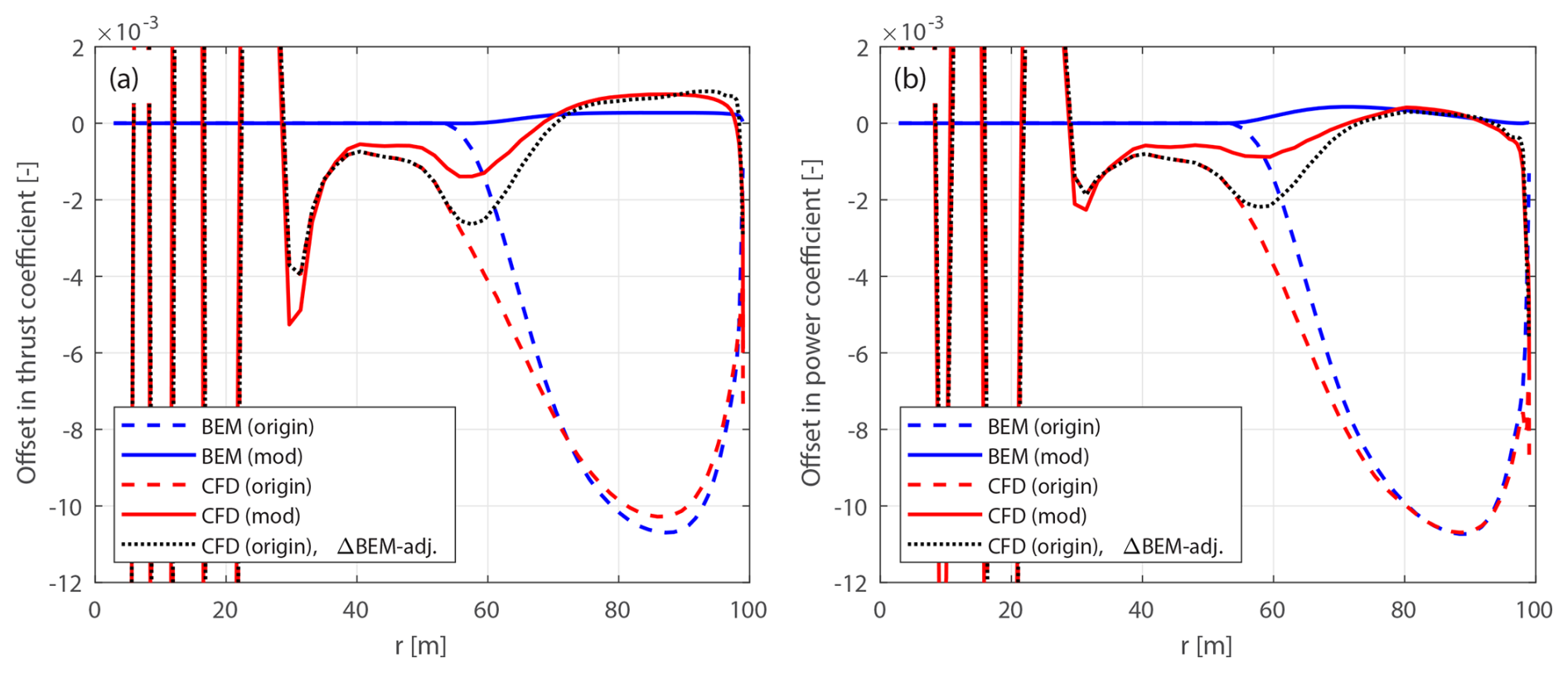
Figure 15Offset in thrust coefficient ΔCt (a) and simplified power coefficient (b) of the original and modified upwind prebent blades W-1-U20 and mW-1-U20 compared to the baseline straight blade, at a wind speed of 20 m s−1.
4.7.2 Lower-loading conditions
Comparisons are also performed for the upwind prebent blades, under operational conditions corresponding to the lower thrust coefficients listed in Table 1. The offsets in thrust and simplified power coefficients for the upwind prebent blades W-1-Uv and mW-1-Uv at a wind speed 20 m s−1 (lowest-loading condition) are presented in Fig. 15, while results under intermediate conditions (12 and 15 m s−1) are shown in Fig. D3 in Appendix D3.12 Similar conclusions apply to the downwind prebent blades W-5-Uv and mW-5-Uv, which are thus not shown in this study.
For the modified prebent blades under all tested lower-loading conditions (12, 15 and 20 m s−1), the thrust coefficient offsets predicted by the BEM method are approximately zero, indicating that the projection effects are effectively removed. The power coefficient offsets have small values, primarily due to the torsion rate drag force, as discussed earlier. The CFD results of the modified prebent blades can directly show the impact of wake geometry due to blade prebend on the loads. Similarly to the high-loading case, a spanwise load redistribution pattern can be observed for all tested lower-loading conditions. This means the wake-induced effects due to blade prebend maintain similar patterns across both high- and low-loading conditions.
The projection effect can be characterized by the load difference between the original and modified prebent blades, for both BEM and CFD results. Comparing the CFD results of the original and modified prebent blades, it is visualized that as the wind speed increases (from 12 to 20 m s−1), the load offset of the modified prebent blade becomes less significant compared to the original prebent blade. This trend indicates that as rotor loading decreases, the wake-induced effects diminish and the projection effects become dominant.
Due to the dominating projection effects under all tested lower-loading conditions, the spanwise load redistribution pattern is not observed in the CFD results of the original prebent blades. Instead, both the BEM method and the CFD solver predict that the loads of the original prebent blades are consistently lower compared to the baseline throughout the span. The projection effects in the original prebent blades are more pronounced than those observed in the original swept blades, discussed previously in Sect. 4.6.2. Nevertheless, the original prebent blades still operate under conditions close to those of the baseline straight blade, with maximum thrust coefficient differences due to projection effects remaining relatively small (approximately 0.015).
The CFD results of the original prebent blade, after the adjustment of subtracting the projection effects based on the BEM results using Eqs. (98) and (99), show very good agreement with the CFD results of the modified prebent blades under all tested lower-loading conditions. This demonstrates that the projection effects in the CFD results of the original prebent blades can be effectively subtracted using this BEM-based adjustment, even under these lower-loading conditions.
Table 5Relative differences (in %) in rotor-integrated thrust and power coefficients due to projection, wake-induced and total effects for the upwind prebent blade W-1, as calculated from the CFD solver under different operational conditions.
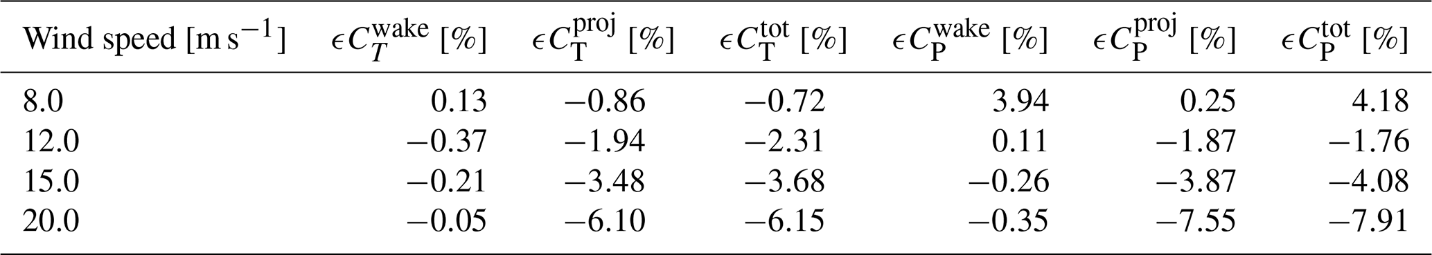
4.7.3 Rotor-integrated effects
Similarly to Sect. 4.6.3, this section uses CFD results to compare the individual contributions of projection and wake-induced effects to rotor-integrated loads. The contributions of projection and wake-induced effects on the rotor-integrated thrust and power coefficients for the upwind prebent blade W-1 across different operational conditions, as determined using the CFD results, are summarized in Table 5. Note that when performing the integration, load offsets relative to the baseline straight blade in the blade root region (radius less than 30 m) are excluded to avoid errors caused by noisy results in this region.
Under the optimal operating condition, the influence of blade prebend on the rotor-integrated power is dominated by the wake-induced effect, with a small positive contribution from projection. In contrast, for the rotor-integrated thrust, the projection effect is more than 6 times as large as the wake-induced effect. As described earlier for swept blades in Sect. 4.6.3, this is due to the spanwise load redistribution being partially canceled out when integrated along the blade span. As wind speed increases and rotor loading decreases, the projection effect rapidly becomes dominant over the wake-induced effect, for both rotor-integrated thrust and power. Compared to the swept blade case, the projection effect is more pronounced in the prebent case under the same operating conditions. For example, at a wind speed of 20 m s−1, the projection effect on rotor thrust is approximately 10 times as large as the wake-induced effect, and for rotor power, it is more than 20 times as large.
4.7.4 Summary
In summary, while the original prebent blade setup in the previous study (Li et al., 2022b) is sufficient to correctly show the wake-induced effects under the optimal operational condition, it becomes insufficient under lower-loading conditions where projection effects dominate. In contrast, the modified prebent blades provide a consistent basis for comparison across all tested operational conditions, enabling the wake-induced effects to be highlighted and directly visualized from the CFD results. Additionally, the projection effects in the CFD results of the original prebent blades can be effectively subtracted using BEM-based adjustments.
4.8 Blades with sweep and prebend combined
In this section, generalized curved blades with both sweep and prebend combined are investigated. The primary objective is to demonstrate that the modified curved blades are necessary to correctly show the wake-induced effects on loads and thus are necessary for a consistent aerodynamic comparison. The results in this section provide insights for future aerodynamic comparisons involving such generalized curved blade configurations.
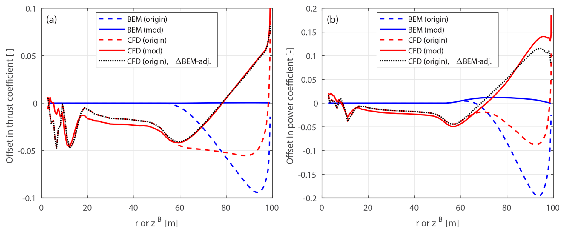
Figure 16Offset in thrust coefficient ΔCt (a) and simplified power coefficients and (b) of the original and modified curved blades C-11 and mC-11, both with backward sweep and upwind prebend combined, compared to the baseline straight blade, at a wind speed of 8 m s−1.
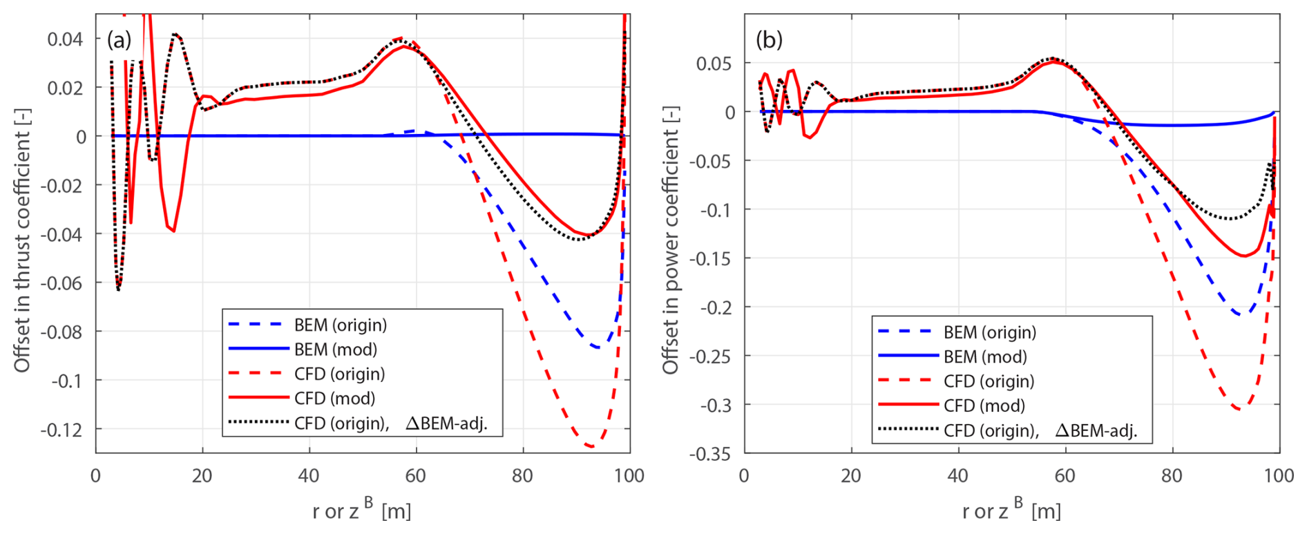
Figure 17Offset in thrust coefficient ΔCt (a) and simplified power coefficients and (b) of the original and modified curved blades C-55 and mC-55, both with forward sweep and downwind prebend combined, compared to the baseline straight blade, at a wind speed of 8 m s−1.
4.8.1 Optimal operational condition
First, comparisons are performed under the optimal operational condition with a uniform inflow velocity of 8 m s−1. The load offsets of both the original and the modified curved blades, compared to the baseline straight blade, are calculated. For the original curved blades, the load offsets ΔCt and are computed using Eqs. (88) and (89) and plotted against the zB coordinates. For the modified curved blades, the load offsets ΔCt and are calculated using Eqs. (94) and (95) and plotted against the radius. Results for the curved blades based on C-11 (backward sweep and upwind prebend) and C-55 (forward sweep and downwind prebend) are depicted in Figs. 16 and 17, respectively. Results for the curved blades based on C-15 (backward sweep and downwind prebend) and C-51 (forward sweep and upwind prebend) are shown in Figs. 18 and 19. In addition, the adjusted CFD results of the original curved blades, obtained by subtracting the projection effects predicted by the BEM method using Eqs. (98) and (99), are included for comparison.
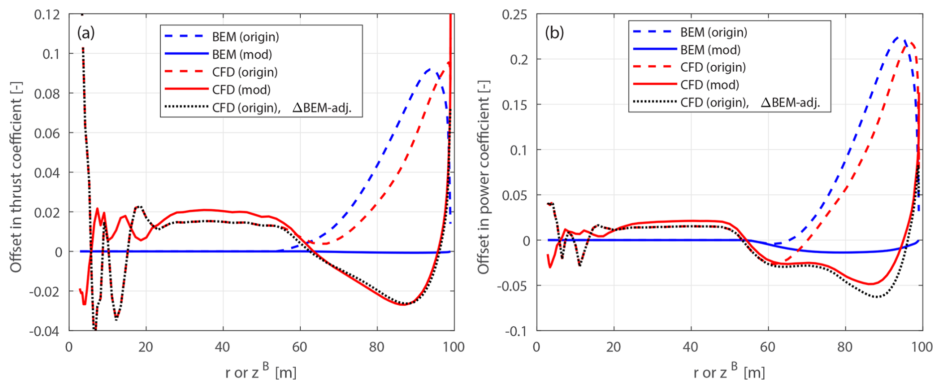
Figure 18Offset in thrust coefficient ΔCt (a) and simplified power coefficients and (b) of the original and modified curved blades C-15 and mC-15, both with backward sweep and downwind prebend combined, compared to the baseline straight blade, at a wind speed of 8 m s−1.
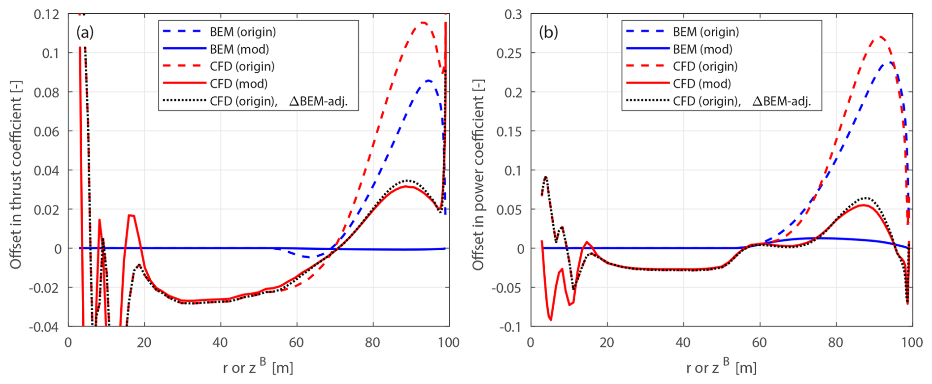
Figure 19Offset in thrust coefficient ΔCt (a) and simplified power coefficients and (b) of the original and modified curved blades C-51 and mC-51, both with forward sweep and upwind prebend combined, compared to the baseline straight blade, at a wind speed of 8 m s−1.
For the original curved blades, the load offsets predicted by the BEM method are primarily due to projection effects. The thrust coefficient offsets are significantly larger compared to those observed for blades with only sweep or only prebend. Specifically, for original curved blades C-11 and C-55, the maximum thrust coefficient decrease is around 0.09 at the zB coordinate of 94 m, while for C-15 and C-51, a maximum increase of approximately 0.09 is reached at the same spanwise location. Compared to the original swept blades B-1 and B-5 and the original prebent blades W-1 and W-5, the thrust coefficient offsets are approximately 5 to 10 times larger. Regarding the simplified power coefficient, the BEM method predicts even larger offsets for these original curved blades. For C-11 and C-55, a maximum decrease of approximately 0.2 is observed at the zB coordinate of 94 m, while for C-15 and C-51, a maximum increase of approximately 0.23 is reached at the same spanwise location. These considerable offsets indicate that the original curved blades with both sweep and prebend combined operate under different conditions compared to the baseline straight blade, primarily due to significant projection effects. This contrasts the blades with only sweep or only prebend in Sect. 4.6 and 4.7, where projection effects were relatively small.
Conversely, for the modified curved blades, the thrust coefficient offsets predicted by the BEM method are approximately zero across the span, indicating that projection effects have been effectively subtracted. This validates the modifications to the chord and twist distributions derived in Sect. 2.8 as well as the approximations in Sect. 2.8.2. In terms of the simplified power coefficient, the BEM method predicts slight increases for the modified curved blades with upwind prebend components (mC-11 and mC-51) and slight decreases for those with downwind prebend components (mC-55 and mC-15). These variations are mostly due to the torsion rate drag in Eq. (78), originating from the main axis being the half-chord line instead of the chord line, as also observed for the blades with only prebend in Sect. 4.7.
The CFD solver accurately captures the effect of changed wake geometries on the aerodynamics, which is quantified by the load offsets between the modified curved blades and the baseline straight blade. A spanwise load redistribution pattern is clearly observed from the CFD results of the modified curved blades with both sweep and prebend combined, similarly to the cases of blades with only sweep in Sect. 4.6 and with only prebend in Sect. 4.7. This redistribution arises from the combination of sweep and prebend applied in the outboard portion of the blade. However, the superposed geometrical changes lead to more complex aerodynamic behavior, with both sweep effects (local effects) and prebend effects (global effects) combined. For mC-11 and mC-51, the loads initially decrease and then increase compared to the baseline straight blade, when moving from the blade root toward the blade tip. For mC-55 and mC-15, the opposite pattern is observed: the loads initially increase and then decrease when moving from the blade root toward the blade tip.
The performance of using the CFD results of the original curved blades (C-bw) to investigate the wake-induced effects for blades with both sweep and prebend combined is also analyzed. Due to strong projection effects, the load offsets of C-11 and C-55 are substantially underestimated, while the load offsets of C-15 and C-51 are significantly overestimated. Consequently, the spanwise load redistribution effect is not evident from the CFD results of the original curved blades. For example, the loads of the original curved blade C-11 are consistently lower compared to the baseline straight blade, except at the very blade tip. For the original curved blade C-55, load redistribution patterns can still be visualized, but the load offsets at the z coordinate of 90 m are overestimated by a factor of 2.
Moreover, the CFD results of the original curved blades adjusted using the BEM results according to Eqs. (98) and (99), labeled “CFD (origin), ΔBEM-adj.” in the figure, show satisfactory agreement with the CFD results of the modified curved blades. This indicates that the projection effects in the CFD and BEM results of the original curved blades are similar, which can be effectively subtracted using this BEM-based adjustment. This also suggests that the cross-flow principle used in the BEM method performs well for generalized curved blades. Additionally, this suggests that BEM and CFD can be integrated into a multi-fidelity optimization framework. In such a framework, BEM could be used for small variations in chord and twist, while CFD would be needed for changes to the main axis geometry.
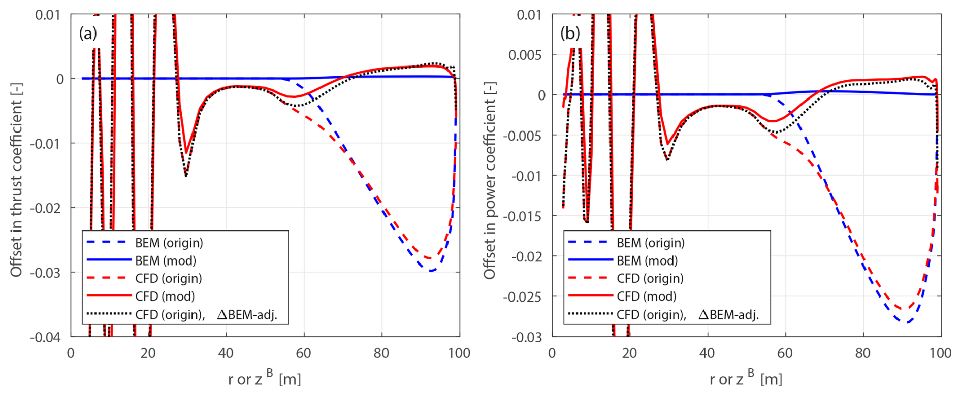
Figure 20Offset in thrust coefficient ΔCt (a) and simplified power coefficients and (b) of the original and modified curved blades C-11-U20 and mC-11-U20 with backward sweep and upwind prebend combined, compared to the baseline straight blade, at a wind speed of 20 m s−1.
Table 6Relative differences (in %) in rotor-integrated thrust and power coefficients due to projection, wake-induced and total effects for the curved blade C-11 (with backward sweep and upwind prebend combined), calculated from CFD under different operational conditions.
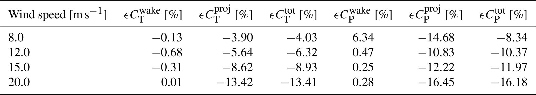
4.8.2 Lower-loading conditions
Further comparisons are made for the original and modified curved blades combining sweep and prebend, under lower-loading conditions, as listed in Table 1. Results for the blades C-11-Uv and mC-11-Uv, which are based on C-11 (with backward sweep and upwind prebend) operating at a wind speed of 20 m s−1, are shown in Fig. 20. Additional results for the curved blades C-bw-Uv and mC-bw-Uv (covering blade geometries C-11, C-15, C-51 and C-55) under lower-loading conditions are provided in Appendix D4.
For the modified curved blades under all tested lower-loading conditions, the BEM method predicts approximately zero thrust coefficient offsets throughout the span, confirming that the projection effect is sufficiently subtracted. For the power coefficient, the small non-zero offset is due to the torsion rate drag force, as previously discussed. The CFD results of the modified curved blades directly show the impact of wake geometry on loads. Across all tested lower-loading conditions (12, 15 and 20 m s−1), a consistent spanwise load redistribution pattern can be observed, similar to that under the optimal condition with high loadings. This indicates that the wake-induced effects, which are due to blade curved geometry, have similar patterns across different loading conditions.
In contrast, the CFD results of the original curved blades do not show this pattern. Both BEM and CFD results show that the loads of the original curved blades C-11-Uv and C-55-Uv are lower compared to the baseline throughout the span, while the loads of C-15-Uv and C-51-Uv are higher. The load difference between the original and modified curved blades represents the projection effects for both BEM and CFD results. Projection effects are already strong at 12 m s−1, compared to the wake-induced effect. As wind speed increases and rotor loading decreases, the wake-induced effects diminish and the projection effects further dominate.
The CFD results of the original curved blades, after subtracting the BEM-predicted projection effects using Eqs. (98) and (99), show satisfactory agreement with the CFD results of the modified curved blades. This demonstrates that the projection effects in the original curved blades, despite their complex combined sweep and prebend geometries, can be effectively subtracted using this adjustment, under all tested lower-loading conditions.
4.8.3 Rotor-integrated effects
Similarly to Sect. 4.6.3 and 4.7.3, this section uses CFD results to compare the individual contributions of projection and wake-induced effects to rotor-integrated loads. The contributions of projection and wake-induced effects on the rotor-integrated thrust and power coefficients, for the curved blade C-11, which features both backward sweep and upwind prebend, across different operational conditions, are shown in Table 6.
Under all operational conditions, the projection effect is clearly dominant over the wake-induced effect. Moreover, for the combined curved blade, the magnitude of the projection effect is substantially larger than in the cases with only sweep or only prebend. As wind speed increases and rotor loading decreases, the dominance of the projection effect becomes even more pronounced. This trend is consistent with the observations for blades with only sweep or prebend.
4.8.4 Summary
In summary, for the tested curved blades combining both sweep and prebend, using the original setup with the same chord and twist distributions as the baseline straight blade is inadequate for investigating the wake-induced effects on loads. The projection effect is significant and dominates the wake-induced effect, leading to misinterpretations of the aerodynamic behavior. In contrast, the curved blades with modified chord and twist distributions enable consistent comparisons across all tested operational conditions. The impact of wake geometry on the load is isolated and can be directly visualized from the CFD results, showing a spanwise load redistribution pattern. Furthermore, it is demonstrated that for the CFD results of the original setup, the projection effects can be effectively subtracted using BEM-based adjustments.
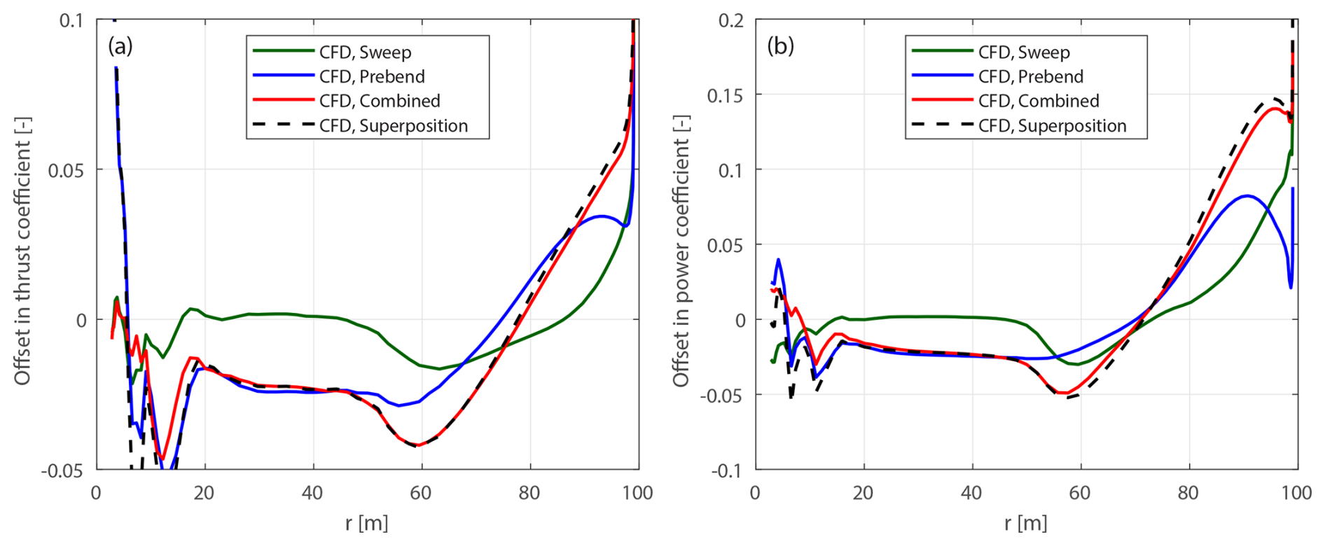
Figure 21Offset in thrust coefficient ΔCt (a) and simplified power coefficient (b) between the modified backward swept blade mB-1, the modified upwind prebent blade mW-1, the modified curved blade mC-11 with both backward sweep and upwind prebend combined, and the superposition of the sweep and prebend offsets, compared to the baseline straight blade, at a wind speed of 8 m s−1.
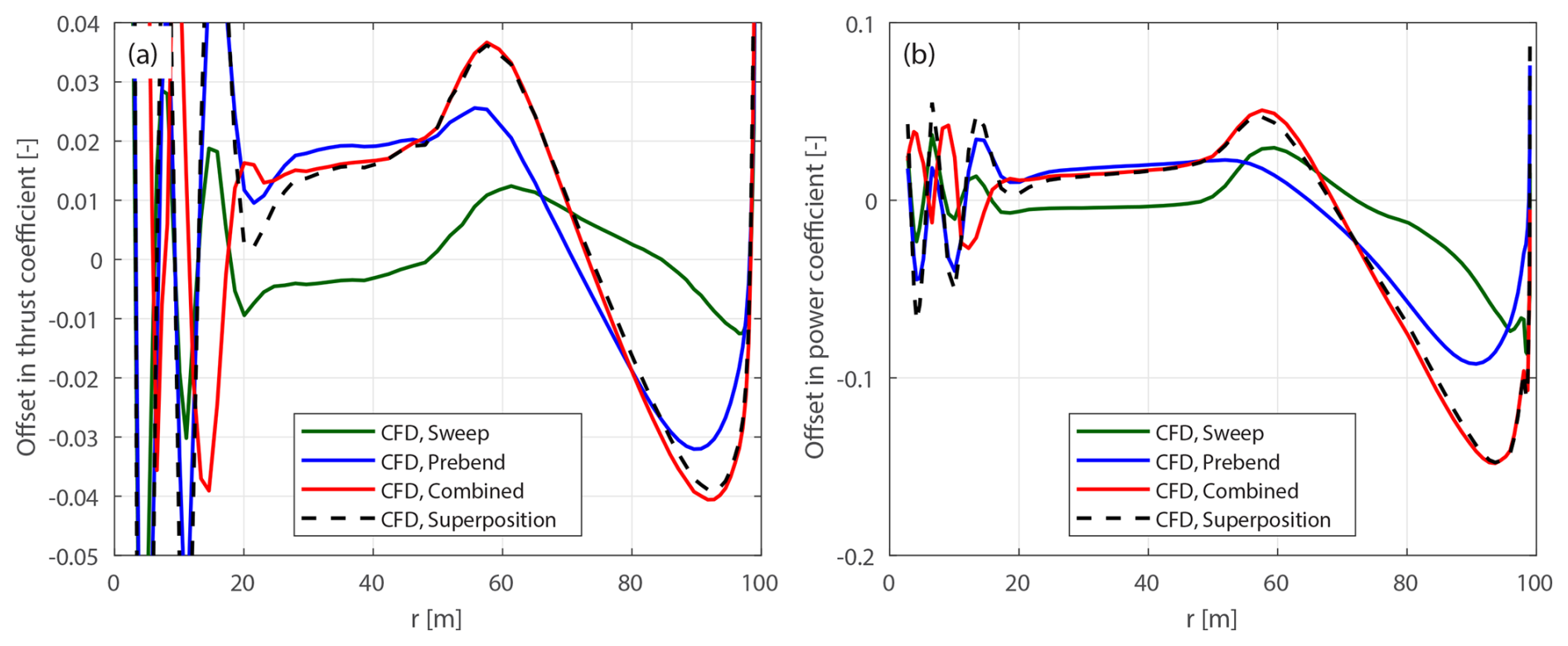
Figure 22Offset in thrust coefficient ΔCt (a) and simplified power coefficient (b) between the modified forward swept blade mB-5, the modified downwind prebent blade mW-5, the modified curved blade mC-55 with both forward sweep and downwind prebend combined, and the superposition of the sweep and prebend offsets, compared to the baseline straight blade, at a wind speed of 8 m s−1.
4.9 Feasibility of superimposing separately modeled sweep and prebend
This section examines whether the wake-induced effects of curved blades with both sweep and prebend combined can be effectively taken into account by modeling the sweep and prebend effects separately and then superimposing them. This approach is tested by comparing the load offsets of a blade with combined sweep and prebend to the summed load offsets of two corresponding blades: one with only sweep and one with only prebend. The main axes of these two projected blades are derived directly from the geometry of the combined curved blade.
For a modified curved blade mC-bw, there are two corresponding projected blades mB-b and mW-w, with either only sweep or only prebend. The main axis geometry of the swept blade mB-b is obtained by removing the prebend component (yB) from the main axis of mC-bw. Similarly, the main axis geometry of the prebent blade mW-w is obtained by removing the sweep component (xB) from the main axis of mC-bw. The main axis of mW-w is further scaled so that each blade section has the same radius as in mC-bw. The chord and twist distributions of mB-b and mW-w are modified according to Sect. 2.8 to ensure that the BEM method predicts the same circulation distribution and inductions as the combined curved blade. For example, for the modified curved blade mC-15 with backward sweep and downwind prebend combined, the corresponding projected blades are the modified backward swept blade mB-1 and the modified downwind prebent blade mW-5.
4.9.1 Optimal operational condition
First, comparisons are performed under the optimal operational condition with a uniform inflow velocity of 8 m s−1. For each modified curved blade mC-bw, load offsets are compared with those of the corresponding modified swept blade mB-b, the modified prebent blade mW-w and the superposition of both offsets (i.e., the sum of the load offsets from mB-b and mW-w). The results for the modified curved blades mC-11, mC-55, mC-15 and mC-51 are shown in Figs. 21 to 24.
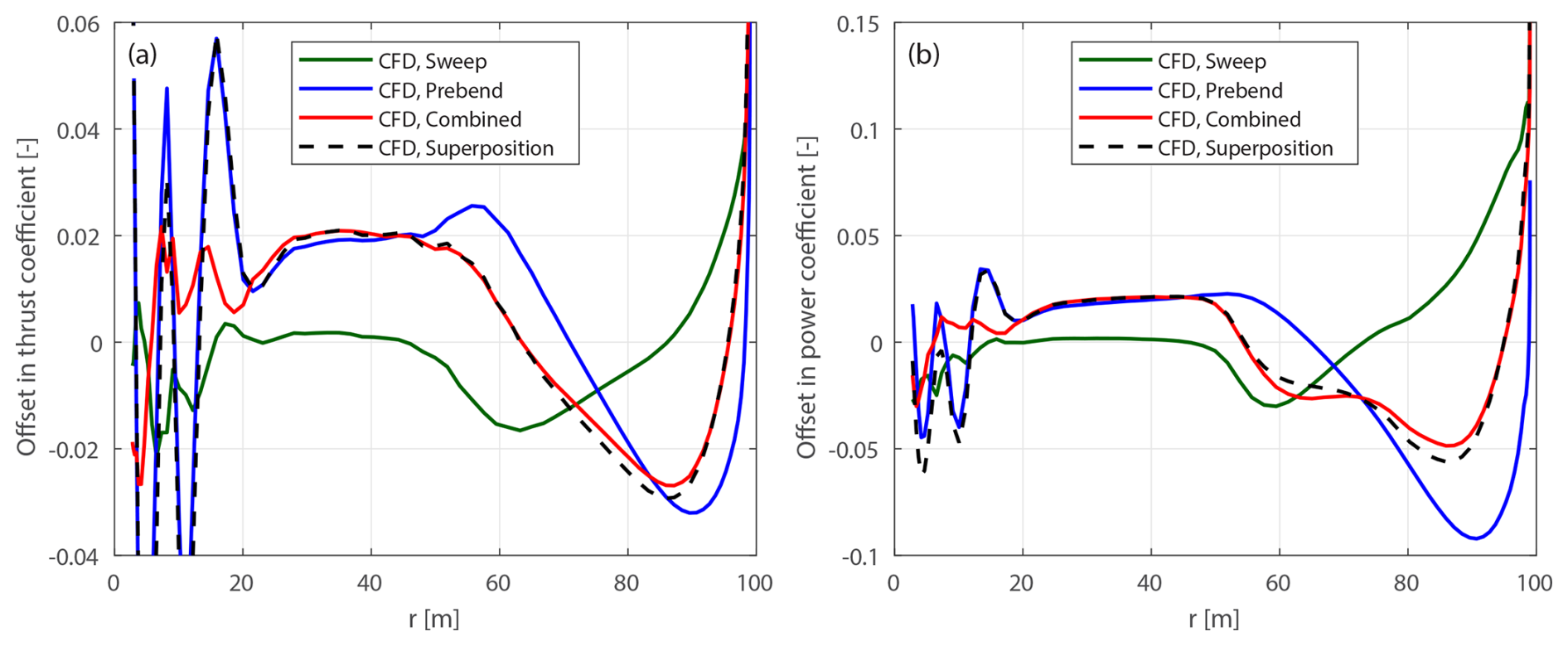
Figure 23Offset in thrust coefficient ΔCt (a) and simplified power coefficient (b) between the modified backward swept blade mB-1, the modified downwind prebent blade mW-5, the modified curved blade mC-15 with both backward sweep and downwind prebend combined, and the superposition of the sweep and prebend offsets, compared to the baseline straight blade, at a wind speed of 8 m s−1.
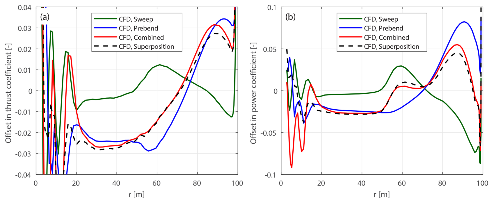
Figure 24Offset in thrust coefficient ΔCt (a) and simplified power coefficient (b) between the modified forward swept blade mB-5, the modified upwind prebent blade mW-1, the modified curved blade mC-51 with both forward sweep and upwind prebend combined, and the superposition of the sweep and prebend offsets, compared to the baseline straight blade, at a wind speed of 8 m s−1.
For all tested modified curved blades, the load offsets are well approximated using the superposition of the load offsets of the two corresponding modified swept and prebent blades. For mC-11 and mC-55, the spanwise load redistribution effects of the corresponding swept and prebent blades are in the same direction. After the superposition, the load redistribution effect of the combined curved blade becomes more significant. For mC-15 and mC-51, the spanwise load redistribution effects of the corresponding swept and prebent blades are in opposite directions. After the superposition, the load redistribution effects partially cancel out, resulting in less significant effects.
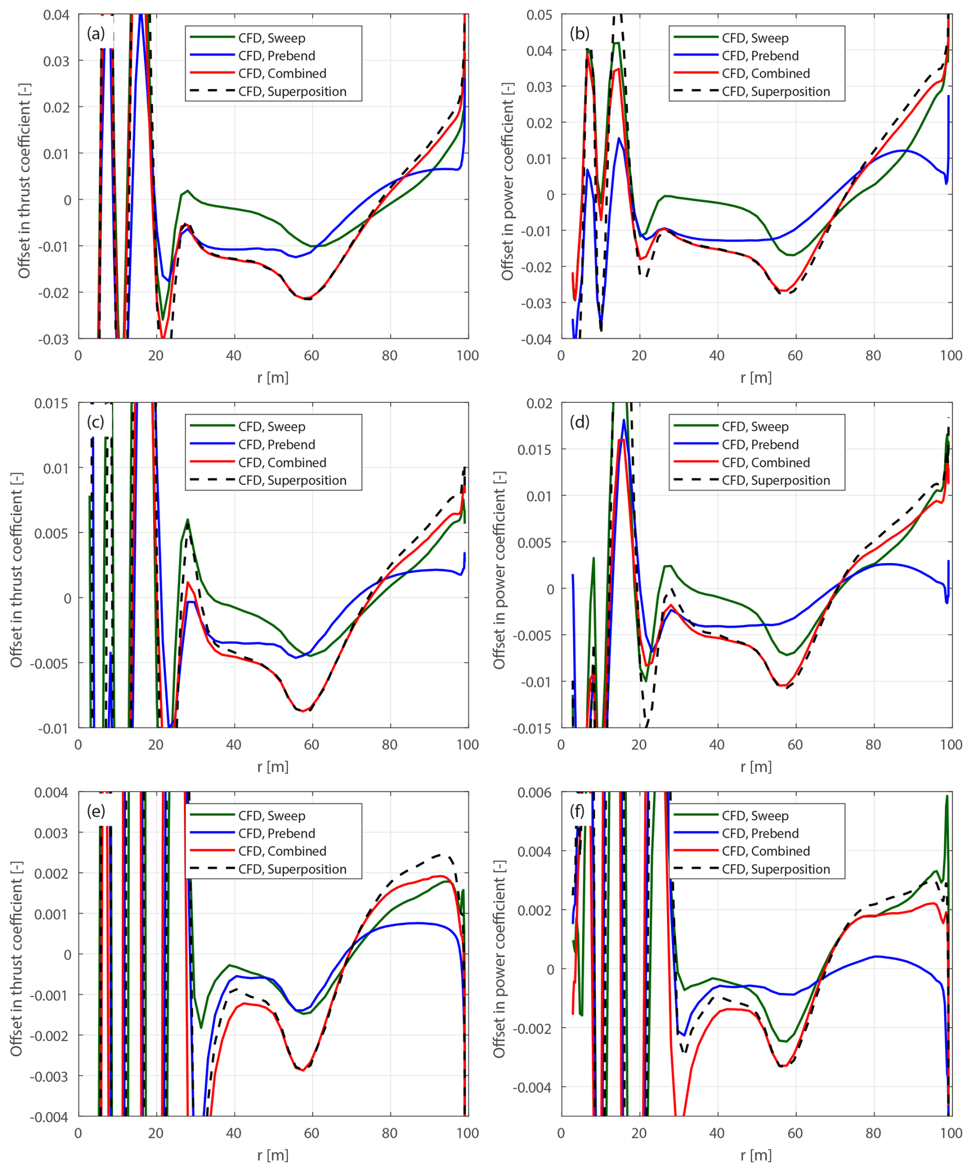
Figure 25Offset in thrust coefficient ΔCt (a, c, e) and simplified power coefficient (b, d, f) of the modified backward swept blades mB-1-Uv, the modified upwind prebent blades mW-1-Uv, the modified curved blade mC-11-Uv with both backward sweep and upwind prebend combined, and the superposition of the sweep and prebend offsets, compared to the baseline straight blade at 12 m s−1 (a, b), 15 m s−1 (c, d) and 20 m s−1 (e, f).
4.9.2 Lower-loading conditions
Further comparisons are performed for the modified curved blades mC-bw-Uv under lower-loading conditions, as listed in Table 1. Results for mC-11-Uv are shown in Fig. 25. Results for the other curved blades based on mC-55, mC-15 and mC-51 are provided in Appendix D5.
For all four cases, the load offsets estimated using the superposition of the CFD results of the two corresponding projected blades show satisfactory agreement with the load offsets of the modified combined curved blades. As wind speed increases and rotor loading decreases, the agreement slightly worsens for the blade tip region (radius greater than 75 m), suggesting that the superposition assumption is less valid. However, since the wake-induced effect decreases as rotor loading decreases, the absolute error of the prediction using the superposition remains small. Overall, the general trends of the load offsets are well captured using this superposition approach.
4.9.3 Summary
In summary, the findings demonstrate that for general curved blades combining both sweep and prebend, the wake-induced effects can be effectively approximated by modeling the sweep and prebend effects separately and then linearly superimposing the results. This approach is confirmed using CFD results, showing promising agreement for different curved blade configurations across various operational conditions. These results provide valuable insights and guidelines for the future development of engineering aerodynamic models for generalized curved blades. For example, they suggest the possibility of directly superimposing the inductions from the coupled near- and far-wake model (Li et al., 2022d), which models only the blade sweep effect, onto those from the vortex cylinder model (Li et al., 2022b), which models only the blade prebend effect, to model a generalized curved blade.
This study establishes a framework for consistent aerodynamic comparisons of blades with different curved geometries, effectively isolating wake-induced effects from projection effects arising from velocity and load projections. This framework employs modified curved blades, with chord and twist distributions adjusted based on the blade's curved geometry, ensuring they operate under the same angles of attack and local thrust coefficients as the baseline straight blade, as predicted by the blade element momentum (BEM) method. Revisiting previous comparisons for blades with either sweep or prebend shows that, under optimal operational conditions with high rotor loadings, the original setup with the same chord and twist distributions is sufficient to show the wake-induced effects. However, under lower-loading conditions, projection effects become dominant over wake geometry effects, leading to inconsistent comparisons. For blades with both sweep and prebend combined, the original setup consistently exhibits significant projection effects across all operational conditions, making it insufficient for consistent comparisons. Using the modified curved blades, more consistent comparisons are achieved. Results from the Reynolds-averaged Navier–Stokes (RANS) CFD solver with the 3-D rotor geometry fully resolved show spanwise load redistribution patterns, similar to those observed in blades with only sweep or only prebend. Additionally, it is shown that projection effects in the CFD results can be effectively subtracted using BEM-based adjustments, confirming the validity of the modified blade setup for more consistent comparisons.
Another key finding of this study is that for blades combining both sweep and prebend, the wake-induced effects can be accurately approximated by linearly superimposing the wake-induced effects from the two corresponding blades, with only sweep and only prebend. This finding supports the approach of modeling sweep and prebend effects on inductions separately and then combining them, offering valuable guidance for the development of future mid-fidelity engineering aerodynamic models for general curved blade geometries.
While this work has focused on steady-state aerodynamic comparisons of rigid blades, the aeroelastic response of curved blades remains an important direction for future research. In particular, the dynamic aerodynamic response of curved blades may differ significantly from that of straight blades. Moreover, the observed load redistribution, through loading or deloading near the tip region, is expected to change both the steady and the dynamic aeroelastic load alleviation associated with blade sweep.
A1 Roman-letter variables used in the present work
| Symbol | Description |
| a, aB | axial induction factor, axial induction factor |
| at the blade | |
| a′ | tangential induction factor |
| a | centrifugal acceleration vector |
| c | chord length |
| CL, CD, CM | 2-D lift, drag and sectional moment coefficients |
| Ct | local thrust coefficient |
| CT | rotor-integrated thrust coefficient |
| / | simplified local power coefficient from |
| the tangential force/in-plane force | |
| / | rotor-integrated simplified power coefficient |
| from the tangential force/in-plane force | |
| F | Prandtl's tip-loss factor |
| ks | normalized bound circulation of all blades |
| NB | number of blades |
| r | radius of a blade section |
| blade curve ratio | |
| Rtot | radius of the rotor |
| rotation matrix around x axis, y axis and z axis | |
| s | curved blade length |
| t, t* | tangent vector, modified tangent vector |
| T | transformation matrix |
| T0 | time constant in unsteady 2-D aerodynamic |
| model | |
| U0 | free wind speed |
| V | 3-D relative velocity magnitude |
| Vrel | 2-D relative velocity magnitude |
A2 Variables in Greek letters used in the present work
| Symbol | Description |
| α | angle of attack |
| β/β* | twist angle (positive for airfoil nose down), |
| in the sectional/modified sectional coordinate | |
| system | |
| Γ | bound vorticity of a blade section |
| δ | position angle |
| Δα | difference in angle of attack: chord point |
| minus chord point | |
| difference in angle of attack: calculation point | |
| minus chord point | |
| difference in angle of attack: chord point | |
| minus calculation point | |
| Δd | blade curve magnitude |
| Δθz | rotational angle between the sectional and |
| modified sectional coordinate systems | |
| mid-chord heaving acceleration of the 2-D airfoil | |
| ζ | ratio of tangents: 2-D sectional flow angle ϕ to |
| inflow angle φ | |
| θp | pitch angle; additional twist angle offset |
| airfoil torsion rate | |
| κ, κ* | dihedral angle, effective dihedral angle |
| ψ, ψ* | sweep angle, effective sweep angle |
| λ | tip-speed ratio of the rotor |
| λr | local speed ratio at a blade section |
| Λtip | tip curve angle |
| μ | ratio of sines: 2-D sectional flow angle ϕ to |
| inflow angle φ | |
| ρ | density of air |
| ϕ | 2-D sectional flow angle, in modified sectional |
| coordinate system | |
| φ | inflow angle |
| Ω | rotational speed |
A3 Subscripts used in the present work
| Symbol | Description |
| at the chord point | |
| at the chord point | |
| x, y, z | in the x, y and z directions |
| L, D, M | due to lift force, drag force, sectional moment |
| N | in normal direction |
| ma | main axis |
| xc | at the xcp-chord point |
| cp | at the calculation point |
| tip | at the blade tip |
| NC | non-circulatory term |
| BEM | from the BEM method |
| CFD | from the CFD solver |
| KJ | from the Kutta–Joukowski analysis |
A4 Superscripts used in the present work
| Symbol | Description |
| B | in blade root coordinate system |
| BL | in blade local coordinate system |
| S | in sectional coordinate system |
| S* | in modified sectional coordinate system |
| str | straight blade |
| cur | curved blade |
| prebend | blade with only prebend and no sweep |
| sweep | blade with only sweep and no prebend |
| origin | original curved blade |
| mod | modified curved blade |
| acc | due to mid-chord heaving acceleration |
| tor | due to torsion rate |
| proj | projection effect |
| wake | wake-induced effect |
| tot | total effects with wake-induced and |
| projection effects combined |
This section shows that, for a given spanwise circulation distribution, the blade element momentum (BEM) method converges to unique induction factors that are independent of the blade geometry (such as sweep or prebend).
First, consider a prescribed spanwise circulation distribution Γ, which is then non-dimensionalized into ks using Eq. (32). As shown in Eq. (38), the tangential induction factor a′ is directly related to ks. Substituting this expression into Eq. (34), the Kutta–Joukowski thrust coefficient Ct,KJ (excluding radial induction) is obtained as
This shows that Ct,KJ is fully determined by ks and the local speed ratio λr, with no direct dependence on blade geometry.
Despite the circulation distribution being prescribed, the BEM method still requires iteration to reach a converged solution due to the application of the tip-loss correction to the axial induction. According to Eq. (36), the blade axial induction factor aB depends on the Kutta–Joukowski thrust coefficient Ct,KJ and the inflow angle φ:
Here, we express aB as a function of ks and φ, noting that Ct,KJ depends entirely on ks.
Next, consider the inflow angle φ. By substituting the expression for a′ in Eq. (38) into the definition of the inflow angle φ in Eq. (15), we find that φ can be represented as a function of aB and ks:
Substituting φ from Eq. (B3) back into Eq. (B2), we arrive at
This results in an implicit equation for aB, which can be solved iteratively where ks is the only prescribed parameter. As a result, once ks is fixed, the iterative procedure converges to a unique aB that is independent of geometric modifications to the blade (e.g., sweep or prebend), providing that these changes do not affect the blade radius.
In conclusion, given a prescribed circulation distribution, the BEM method will converge to the same inductions and also the same Kutta–Joukowski thrust and power coefficients, regardless of the blade geometry.
In this section, we derive the total contribution of non-circulatory forces and moments to the local thrust and power coefficients under steady-state operational conditions. Although the chord line is chosen as the main reference axis for simplicity, the conclusions presented here are general and can be extended to other main-axis definitions, as discussed in Sect. 2.8.2.
Non-circulatory forces and moments arise when the airfoil experiences effective motions, specifically, a mid-chord heaving acceleration () perpendicular to the chord line and a torsion rate (). Under steady-state conditions, these effective motions are only due to the projection of the rotor's angular velocity and centrifugal acceleration originating from rotor rotation. The mid-chord heaving acceleration is defined to be positive when directed from the pressure side to the suction side of the airfoil. The torsion rate is defined to be positive in the nose-up direction. The expressions for and are given in Eqs. (26) and (24), respectively.
First, there are non-circulatory normal forces perpendicular to the airfoil that arise due to mid-chord heaving acceleration and the torsion rate. The corresponding force coefficients are given by
Here, the time constant T0 is introduced, following the literature (Hansen et al., 2004; Bergami and Gaunaa, 2012).
Additionally, there are sectional moments due to mid-chord acceleration and the torsion rate, with corresponding moment coefficients at the chord point being
Summing these components, the total non-circulatory normal force and moment coefficients are
Additionally, a non-circulatory drag force due to the torsion rate (Li et al., 2022c) is accounted for:
The non-circulatory lift and drag coefficients at the chord point are
These lift and drag increments, together with the moment term, are incorporated into the thrust and power coefficient formulations in Eqs. (64) to (66) to determine their net effects:
It can be further concluded that the non-circulatory lift and drag contribute to both thrust and power, while the non-circulatory moment only contributes to power. Further, the contribution of the non-circulatory torsion rate drag in Eq. (C8) to thrust is negligible since its magnitude is much smaller than the lift force. Nevertheless, its contribution to power is still considered in this study. In addition, approximations are applied, assuming small sweep, prebend and inflow angles. The total contribution of non-circulatory forces and moments to the local thrust and power coefficients is approximated as
C1 Straight blades forming a planar rotor
For the special case where the blade is straight and forms a planar rotor, both the effective sweep angle ψ* and the effective prebend angle κ* are zero. Consequently, the projected effective mid-chord heaving acceleration and effective torsion rate are also zero. As a result, the contributions of non-circulatory forces and moments to the local thrust and power coefficients are zero. This is also confirmed numerically in the following sections.
Figure C1Contributions of the non-circulatory forces (a) and moments (b) to the local thrust and power coefficients of the baseline straight blade and the modified backward swept blades mB-1 to mB-4, at different wind speeds.
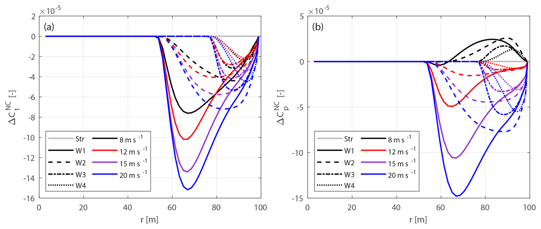
Figure C2Contributions of the non-circulatory forces (a) and moments (b) to the local thrust and power coefficients of the baseline straight blade and the modified upwind prebent blades mW-1 to mW-4, at different wind speeds.
C2 Blades with only sweep
For the special condition where the blade has sweep but no prebend (), the effective torsion rate and the mid-chord heaving acceleration, given in Eqs. (24) and (26), are simplified assuming that both the effective sweep angle ψ* and the twist angle β are small:
Therefore, the total contributions of non-circulatory forces and moments to the thrust and power coefficients are approximately zero:
Numerical simulations were performed using the backward swept blades mB-1 to mB-4, whose parameters are listed in Table 3. Comparisons across different operational conditions, listed in Table 1, confirm these approximations. In addition, the baseline straight blade is included as a reference. The results for the non-circulatory force and moment contributions to the local thrust and power coefficients are shown in Fig. C1.
For the baseline straight blade, the total contributions of non-circulatory forces and moments to thrust and power are zero. For the four backward swept blades, the maximum magnitudes of the local thrust and power coefficients due to the non-circulatory forces and moments are only and , respectively, which are negligible.
C3 Blades with only prebend
For the special condition where the blade has prebend but no sweep (), the effective torsion rate and the mid-chord heaving acceleration are
Substituting these into Eq. (C6), the non-circulatory normal force coefficient becomes
Assuming that the tangential induction factor a′ is much smaller than 1, the following approximation can be made:
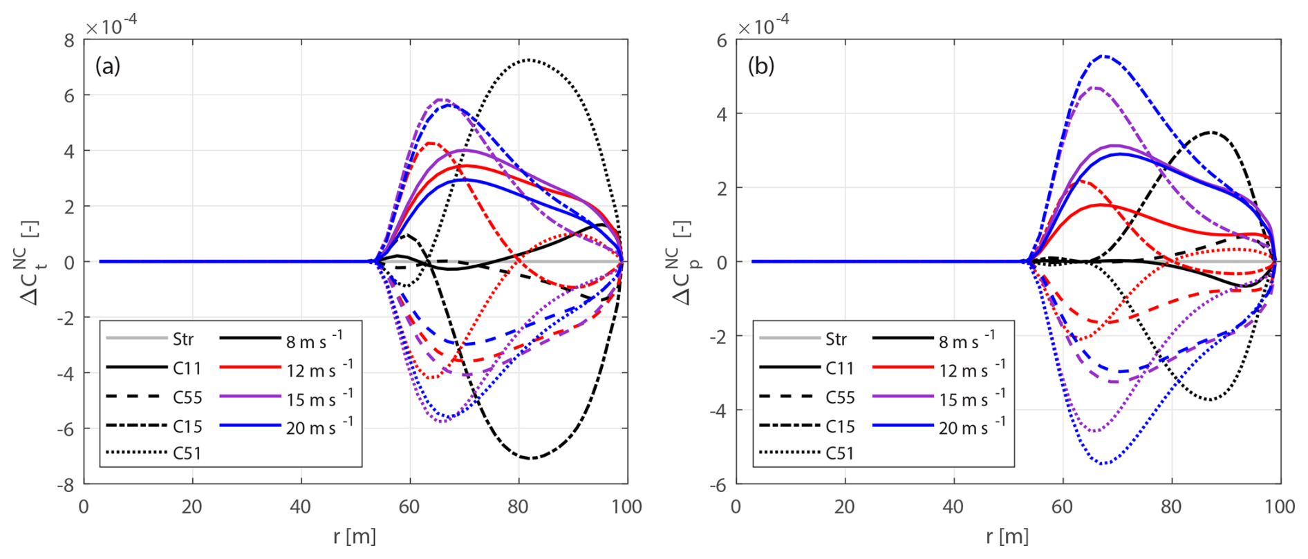
Figure C3Contributions of non-circulatory forces (a) and moments (b) to the local thrust and power coefficients of the baseline straight blade and the modified curved blades mC-11, mC-55, mC-15 and mC-51, at different wind speeds.
Further, inserting Eq. (21) and assuming the inflow angle φ and the twist angle β are both small angles, the non-circulatory normal force is then approximately zero.
Inserting Eq. (C28) into Eqs. (C16) and (C17), the contributions to the thrust and power coefficients are approximately zero:
Inserting Eq. (C28) into Eq. (C7), the non-circulatory moment coefficient is approximated as
Further, inserting Eqs. (C8) and (C31) into Eq. (C30), the equation is further manipulated to be
With further substitutions from Eqs. (62) and (C27) and assuming a small inflow angle φ, the total contribution to the local power coefficient from non-circulatory forces and moments is approximately zero.
To confirm this numerically, the upwind prebent blades mW-1 to mW-4, with parameters listed in Table 3, under different operational conditions listed in Table 1 are used for comparison. The contribution of the non-circulatory force and moment to the local thrust and power coefficients is shown in Fig. C2.
For these four upwind prebent blades, the maximum contribution of non-circulatory forces and moments to the local thrust and power coefficients is only , which is negligible.
C4 Blades with sweep and prebend combined
For the generalized case where the blade has both sweep and prebend combined, the expression for the mid-chord heaving acceleration becomes more complex. To simplify the derivation, approximations are firstly applied. Given that both the effective sweep angle ψ* and the modified twist angle β* are small, Eq. (26) can be approximated as
Substituting Eqs. (24) and (C34) into Eq. (C6), the non-circulatory normal force coefficient becomes
By inserting Eq. (21) and applying the approximation in Eq. (C27), further simplifications are made. Further, assuming that ψ*, κ*, β* and the inflow angle φ are all small angles for the region where the blade has sweep or prebend, the non-circulatory normal force is then approximately zero.
Substituting Eq. (C36) into Eqs. (C16) and (C17), the total contributions to the local thrust and power coefficients are
Inserting Eq. (C36) into Eq. (C7), the approximated non-circulatory moment coefficient takes the same form as for the special case with prebend only:
Next, substituting Eqs. (C8) and (C39) into Eq. (C38), we manipulate the expression further:
By assuming ψ* is small and inserting Eq. (7), the norm can be approximated as
Inserting Eqs. (51), (52) and (C27) and assuming that the 2-D flow angle ϕ is similar to the inflow angle φ, μ≈1. Furthermore, assuming that κ* and φ are small angles, the total contribution of the non-circulatory forces and moments to the local power coefficient becomes approximately zero.
To validate these derivations, numerical comparisons were conducted using blades mC-11, mC-55, mC-15 and mC-51 with sweep and prebend combined. Operational conditions are detailed in Table 1. The contributions of the non-circulatory forces and moments to the local thrust and power coefficients are shown in Fig. C3.
For these four combined curved blades, the maximum magnitudes of contributions of non-circulatory forces and moments to the local thrust and power coefficients are and , respectively, which are negligible.
D1 Straight blades
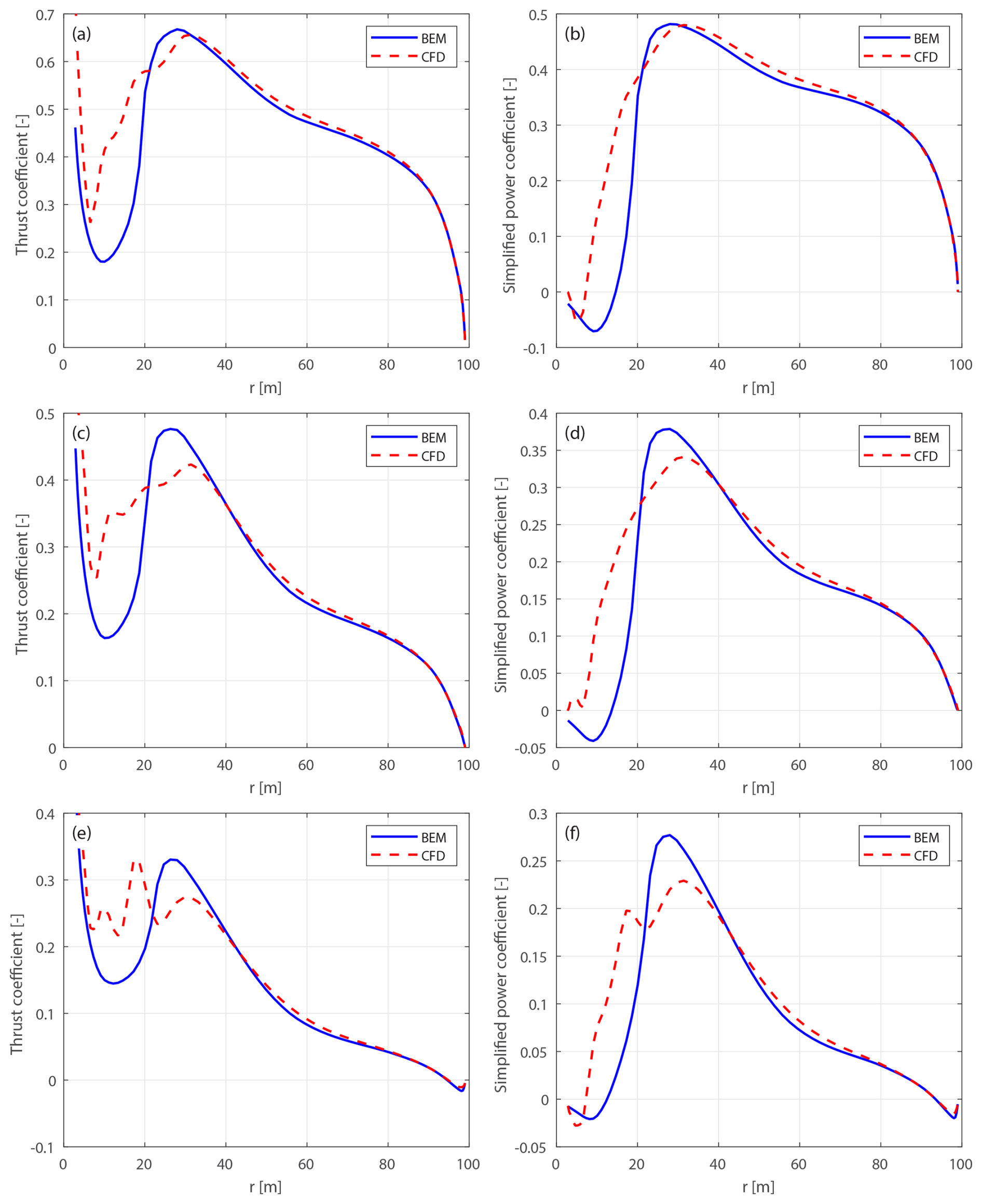
Figure D1Thrust coefficient Ct (a, c, e) and simplified power coefficient (b, d, f) of the baseline straight blade, for wind speeds at 12 m s−1 (a, b), 15 m s−1 (c, d) and 20 m s−1(e, f).
D2 Blades with only sweep
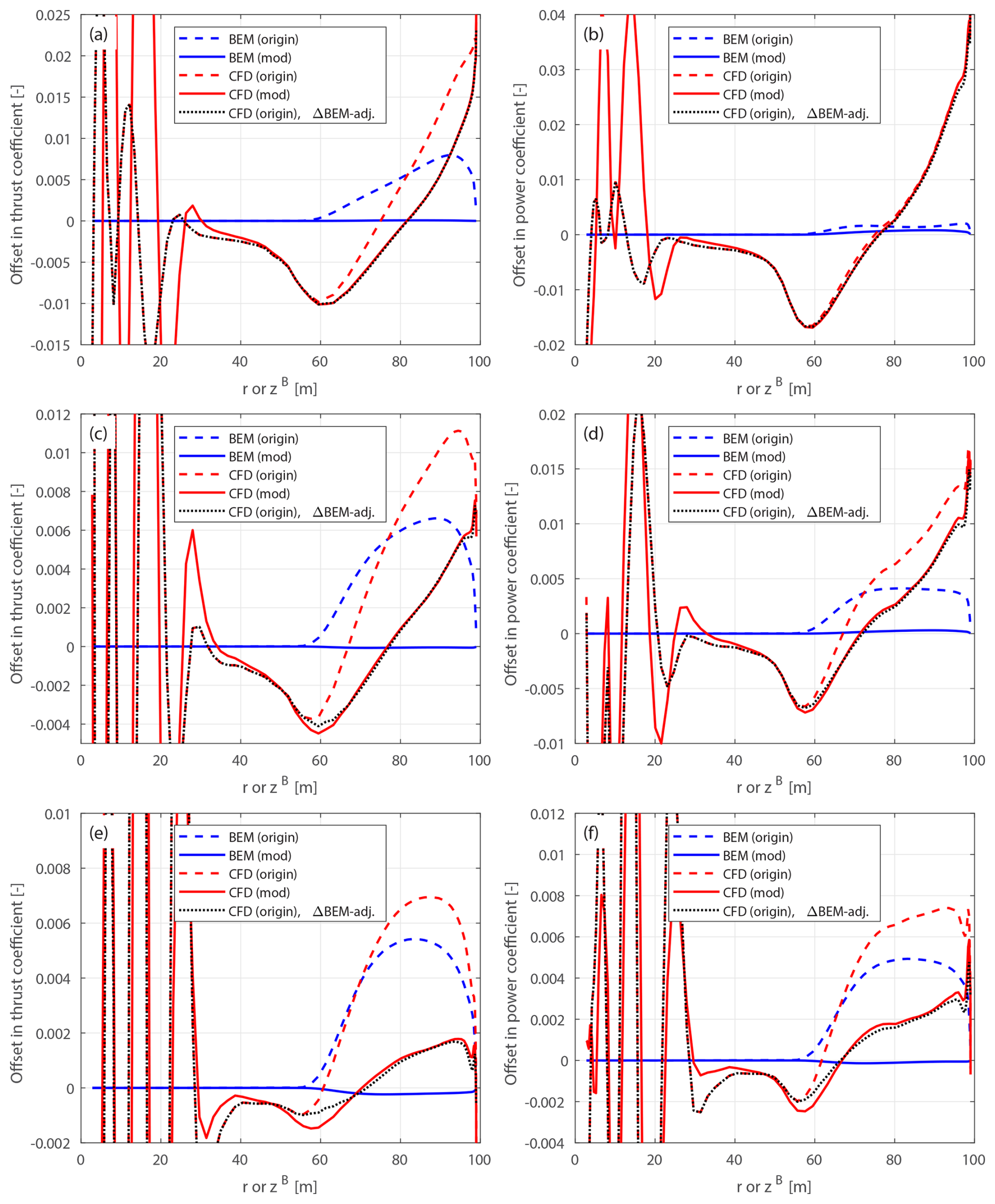
Figure D2Offset in thrust coefficient ΔCt (a, c, e) and simplified power coefficients and (b, d, f) of the original and modified backward swept blades B-1-Uv and mB-1-Uv compared to the baseline straight blade, for wind speeds at 12 m s−1(a, b), 15 m s−1 (c, d) and 20 m s−1 (e, f).
D3 Blades with only prebend
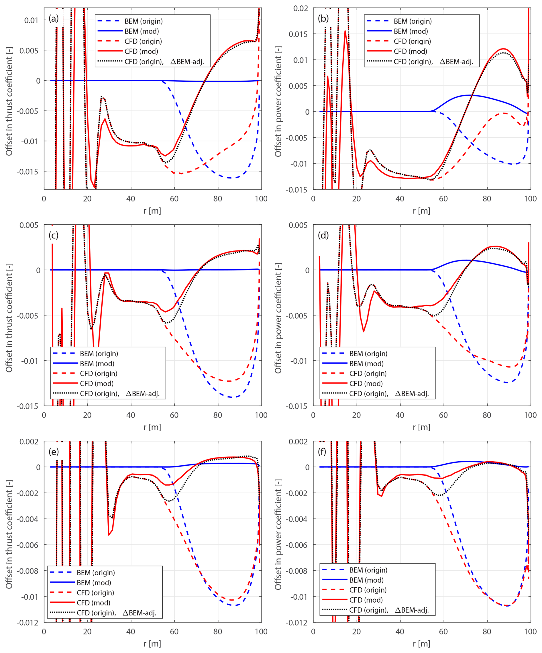
Figure D3Offset in thrust coefficient ΔCt (a, c, e) and simplified power coefficient (b, d, f) of the original and modified upwind prebent blades W-1-Uv and mW-1-Uv compared to the baseline straight blade, for wind speeds at 12 m s−1 (a, b), 15 m s−1 (c, d) and 20 m s−1 (e, f).
D4 Blades combining sweep and prebend
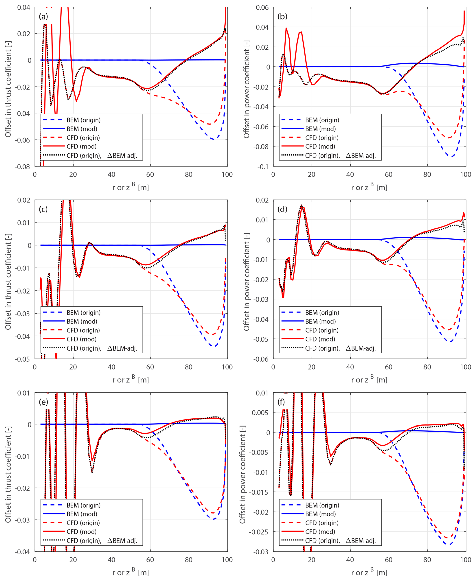
Figure D4Offset in thrust coefficient ΔCt (a, c, e) and simplified power coefficients and (b, d, f) of the original and modified curved blades C-11-Uv and mC-11-Uv with backward sweep and upwind prebend combined, compared to the baseline straight blade: at 12 m s−1 (a, b), 15 m s−1 (c, d) and 20 m s−1 (e, f).
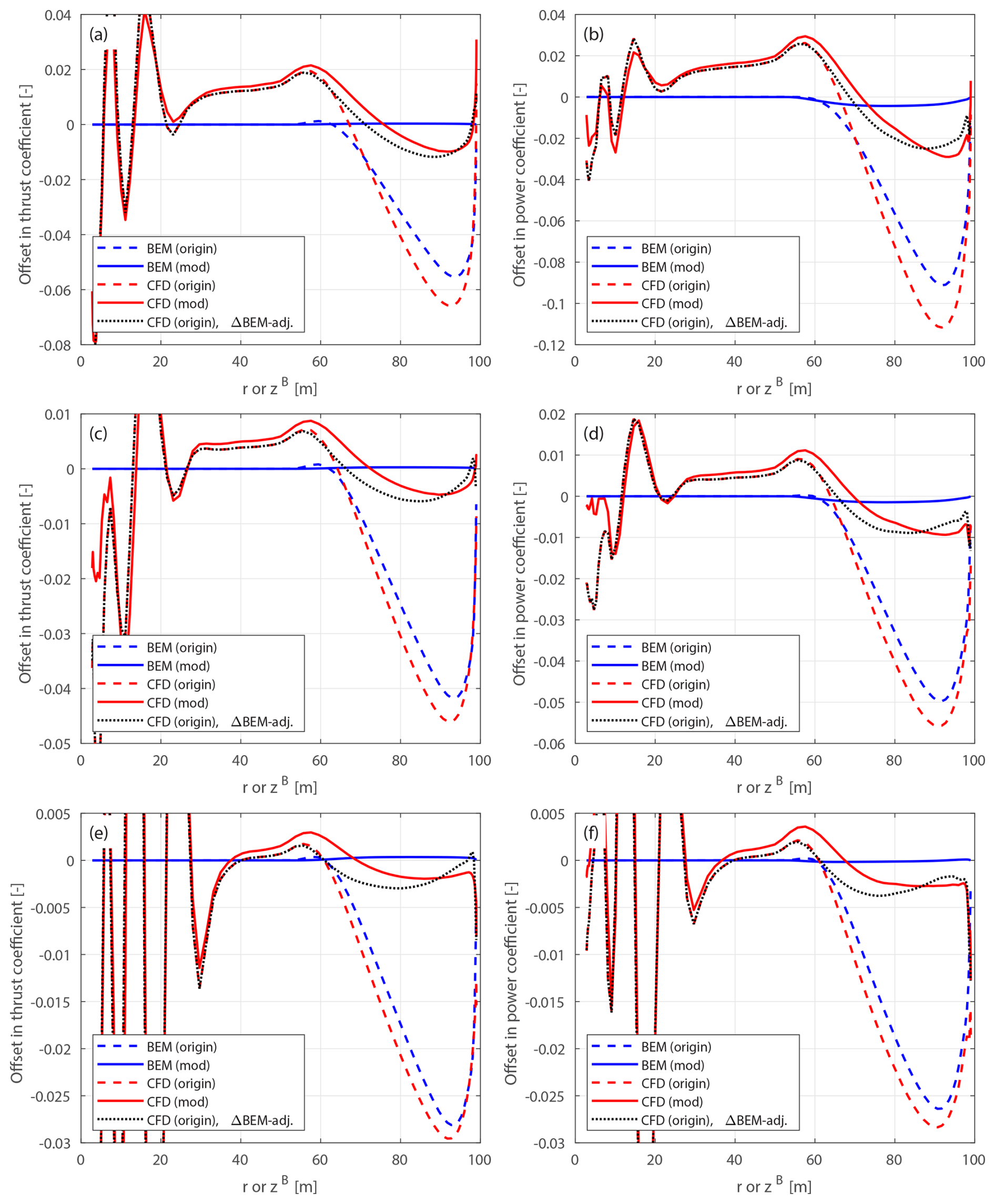
Figure D5Offset in thrust coefficient ΔCt (a, c, e) and simplified power coefficients and (b, d, f) of the original and modified curved blades C-55-Uv and mC-55-Uv with forward sweep and downwind prebend combined, compared to the baseline straight blade: at 12 m s−1 (a, b), 15 m s−1 (c, d) and 20 m s−1 (e, f).
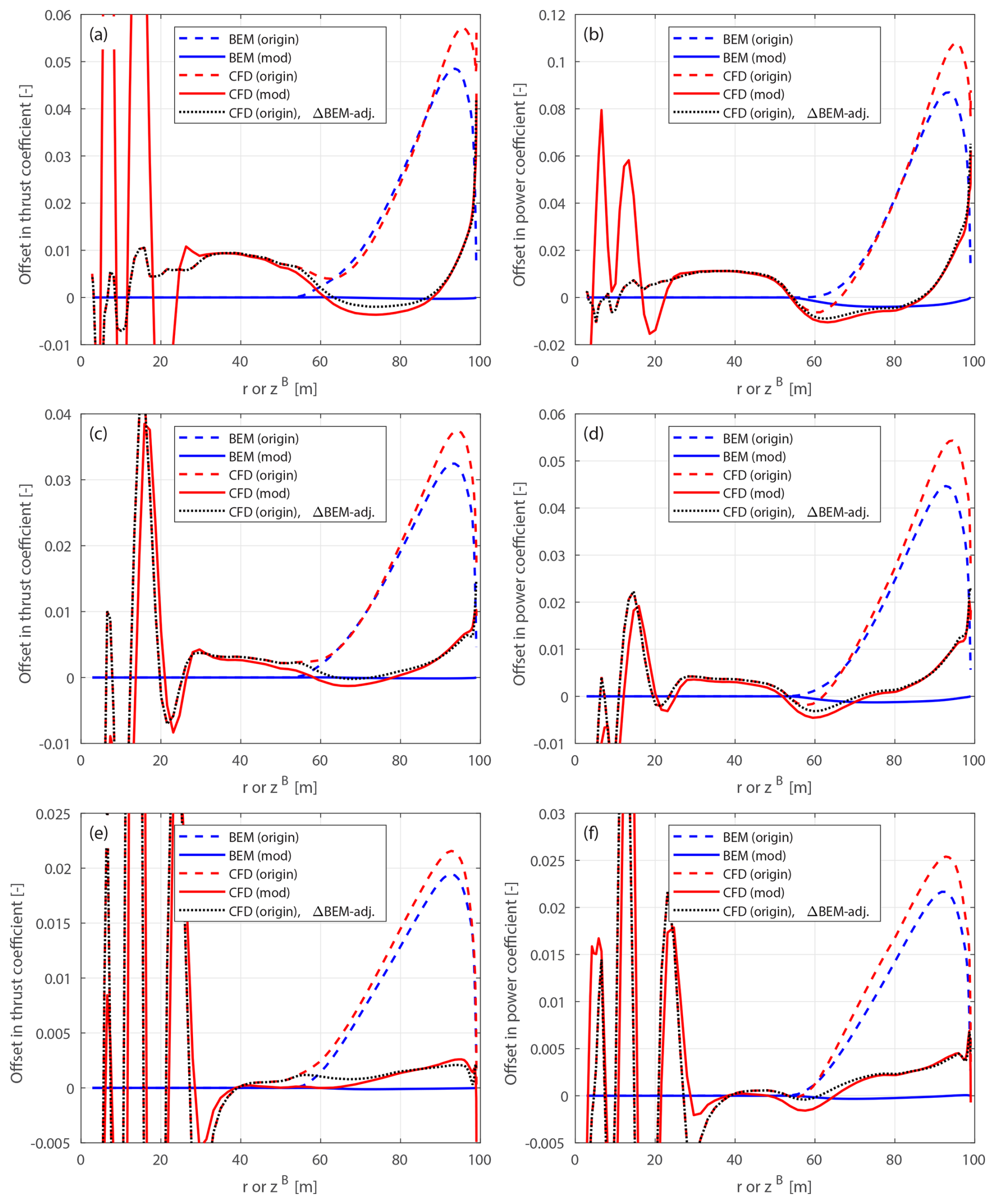
Figure D6Offset in thrust coefficient ΔCt (a, c, e) and simplified power coefficients and (b, d, f) of the original and modified blades C-15-Uv and mC-15-Uv with backward sweep and downwind prebend combined, compared to the baseline straight blade at 12 m s−1 (a, b), 15 m s−1 (c, d) and 20 m s−1 (e, f).
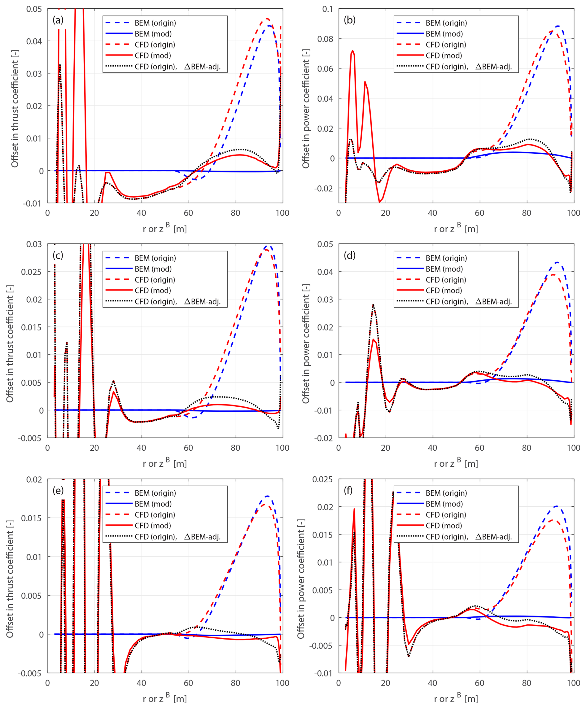
Figure D7Offset in thrust coefficient ΔCt (a, c, e) and simplified power coefficients and (b, d, f) of the original and modified curved blades C-51-Uv and mC-51-Uv with forward sweep and upwind prebend combined, compared to the baseline straight blade at 12 m s−1 (a, b), 15 m s−1 (c, d) and 20 m s−1 (e, f).
D5 Superposition of sweep and prebend
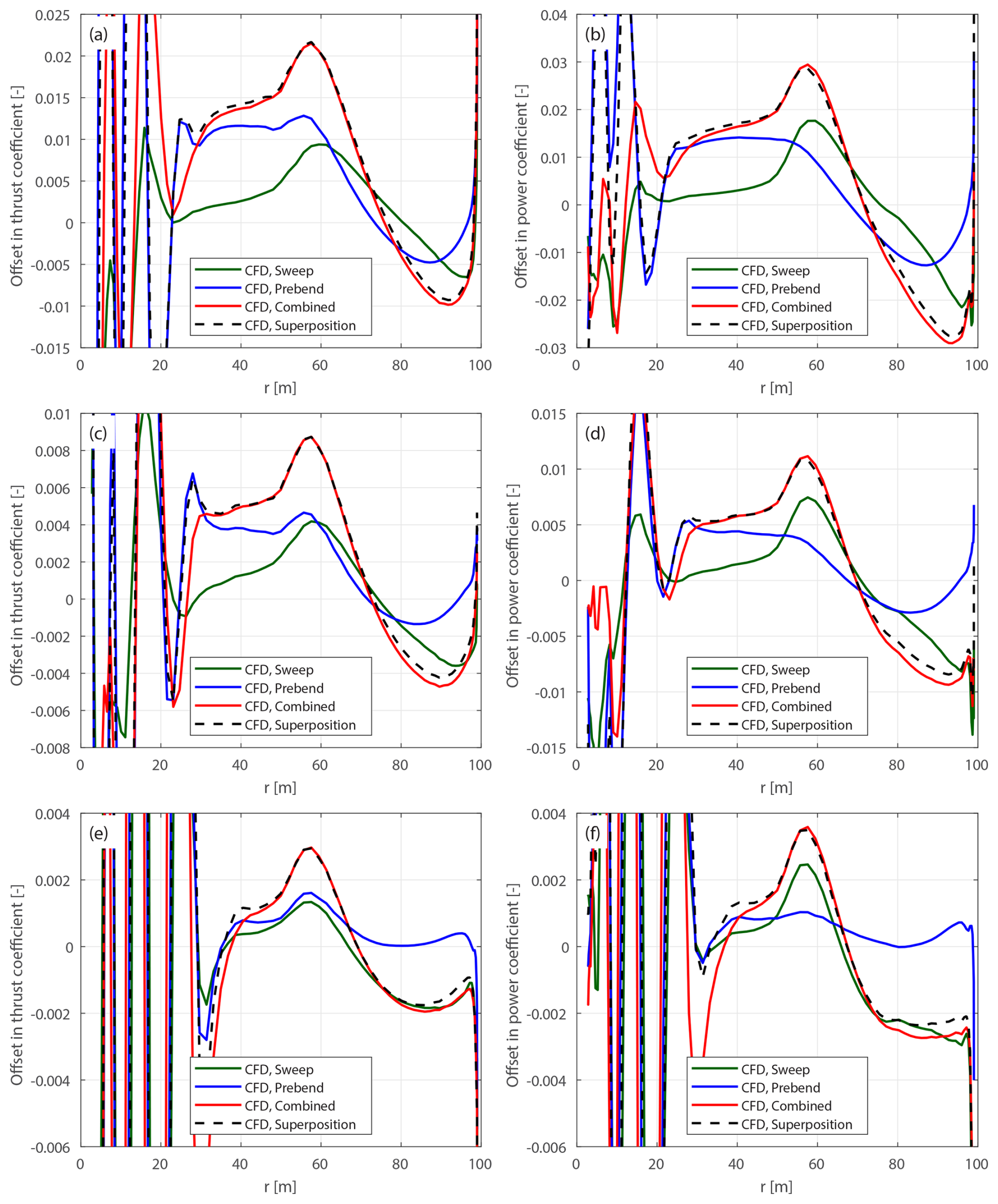
Figure D8Offset in thrust coefficient ΔCt (a, c, e) and simplified power coefficient (b, d, f) of the modified forward swept blades mB-5-Uv, the modified downwind prebent blades mW-5-Uv, the modified curved blade mC-55-Uv with both forward sweep and downwind prebend combined and the superposition of the sweep and prebend offsets, compared to the baseline straight blade: at 12 m s−1 (a, b), 15 m s−1 (c, d) and 20 m s−1 (e, f).
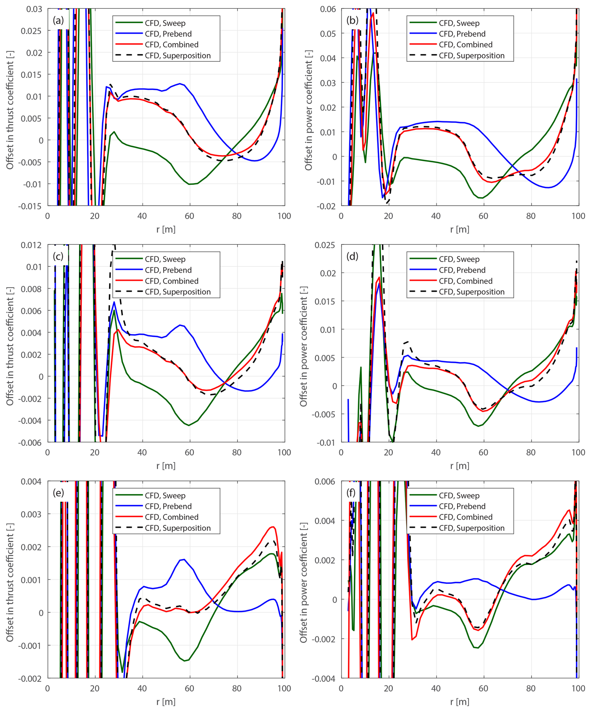
Figure D9Offset in thrust coefficient ΔCt (a, c, e) and simplified power coefficient (b, d, f) of the modified backward swept blades mB-1-Uv, the modified downwind prebent blades mW-5-Uv, the modified curved blade mC-15-Uv with both backward sweep and downwind prebend combined and the superposition of the sweep and prebend offsets, compared to the baseline straight blade: at 12 m s−1 (a, b), 15 m s−1 (c, d) and 20 m s−1 (e, f).
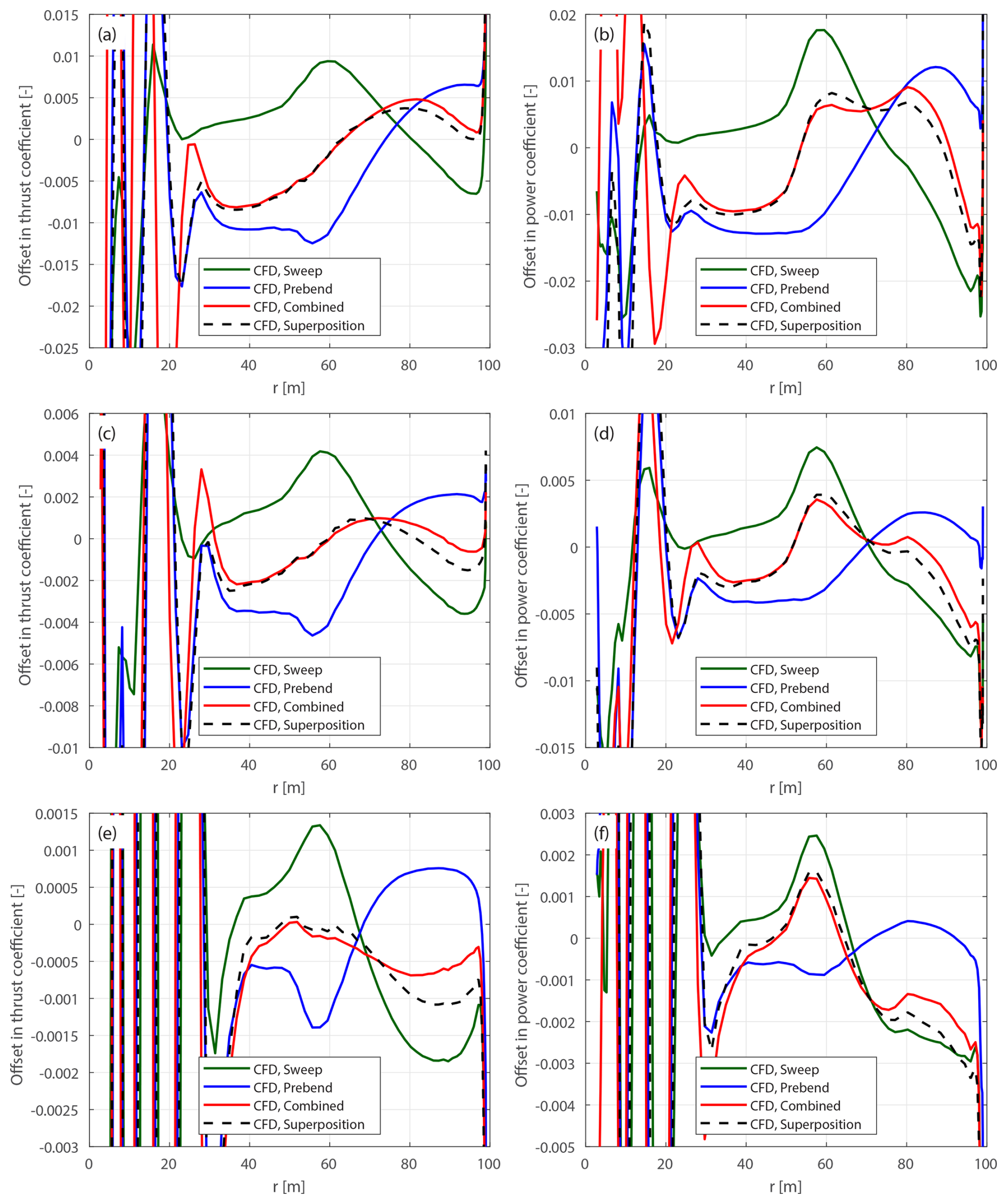
Figure D10Offset in thrust coefficient ΔCt (a, c, e) and simplified power coefficient (b, d, f) of the modified forward swept blades mB-5-Uv, the modified upwind prebent blades mW-1-Uv, the modified curved blade mC-51-Uv with both forward sweep and upwind prebend combined and the superposition of the sweep and prebend offsets, compared to the baseline straight blade: at 12 m s−1 (a, b), 15 m s−1 (c, d) and 20 m s−1 (e, f).
The 2-D airfoil data used in this article are generated with 2-D fully turbulent RANS computations https://doi.org/10.2172/1529216 (Bortolotti et al., 2019). The supplementary material containing additional figures for different curved blade geometries is available in an internet appendix https://doi.org/10.5281/zenodo.13149533 (Li et al., 2025).
The concept of disentangling projection effects and wake geometry effects, as well as establishing a consistent framework for aerodynamic benchmarking, originated from discussions among AL, MG, GRP and KL. In 2020, GRP conducted an initial study, demonstrating analytically and numerically that the BEM method is not able to predict an aerodynamic efficiency benefit for a swept blade compared to a straight blade. The application of the BEM method to general curved blades was described by AL, with contributions from MG, GRP and KL. The derivations of the modified chord and twist distributions were performed by AL. The derivations of the contribution of non-circulatory loads to a curved blade under steady-state conditions were also performed by AL. The results from the fully resolved CFD solver and the BEM method were computed and post-processed by AL, with all co-authors contributing to analysis and interpretation. The overall analysis was conducted collaboratively by AL, MG, GRP and KL. All authors jointly formulated the study's conclusions and contributed to writing the manuscript.
DTU Wind and Energy Systems develops and distributes the Navier–Stokes solver EllipSys3D on commercial and academic terms. DTU Wind and Energy Systems also develops, supports and distributes HAWC2 on commercial terms, and HAWC2 is available free of charge for educational and academic research purposes.
Publisher’s note: Copernicus Publications remains neutral with regard to jurisdictional claims made in the text, published maps, institutional affiliations, or any other geographical representation in this paper. While Copernicus Publications makes every effort to include appropriate place names, the final responsibility lies with the authors. Views expressed in the text are those of the authors and do not necessarily reflect the views of the publisher.
The authors would like to thank their colleague Frederik Zahle at DTU Wind and Energy Systems for setting up the fully scripted mesh generation and post-processing for the Reynolds-averaged Navier–Stokes (RANS) simulations in EllipSys3D. The authors would like to thank their colleague Antariksh Dicholkar at DTU Wind and Energy Systems for insightful discussions. Computational and storage resources were provided by the Sophia HPC Cluster at DTU (https://doi.org/10.57940/fafc-6m81, DTU, 2019). An earlier version of this paper was revised with the assistance of AI tools, including OpenAI's ChatGPT (GPT-3.5, GPT-4, GPT-4o, GPT-4.1, GPT-4.5, o1-preview and o1), which were used to generate suggestions to improve language and wording based on an existing draft. The manuscript underwent multiple rounds of revision by the authors, with AI-generated suggestions selectively incorporated and extensively modified.
This research has been supported by the Energiteknologisk udviklings- og demonstrationsprogram (grant no. 64021-2062). This work was supported by the AMTip project, funded by the Energy Technology Development and Demonstration Program (EUDP) (case no. 64021-2062).
This paper was edited by Emmanuel Branlard and reviewed by three anonymous referees.
Barlas, T., Ramos-García, N., Pirrung, G. R., and González Horcas, S.: Surrogate-based aeroelastic design optimization of tip extensions on a modern 10 MW wind turbine, Wind Energ. Sci., 6, 491–504, https://doi.org/10.5194/wes-6-491-2021, 2021. a
Barlas, T., Pirrung, G. R., Ramos-García, N., González Horcas, S., Li, A., and Madsen, H. A.: Atmospheric rotating rig testing of a swept blade tip and comparison with multi-fidelity aeroelastic simulations, Wind Energ. Sci., 7, 1957–1973, https://doi.org/10.5194/wes-7-1957-2022, 2022. a, b
Behrens de Luna, R., Marten, D., Barlas, T., Horcas, S. G., Ramos-García, N., Li, A., and Paschereit, C. O.: Comparison of different fidelity aerodynamic solvers on the IEA 10 MW turbine including novel tip extension geometries, Journal of Physics. Conference Series, 2265, 032002, https://doi.org/10.1088/1742-6596/2265/3/032002, 2022. a
Bergami, L. and Gaunaa, M.: ATEFlap Aerodynamic Model, a dynamic stall model including the effects of trailing edge flap deflection, Danmarks Tekniske Universitet, Risø Nationallaboratoriet for Bæredygtig Energi, ISBN 9788755039346, 2012. a, b, c, d, e
Boorsma, K., Wenz, F., Lindenburg, K., Aman, M., and Kloosterman, M.: Validation and accommodation of vortex wake codes for wind turbine design load calculations, Wind Energ. Sci., 5, 699–719, https://doi.org/10.5194/wes-5-699-2020, 2020. a
Bortolotti, P., Tarrés, H. C., Dykes, K., Merz, K., Sethuraman, L., Verelst, D., and Zahle, F.: Systems Engineering in Wind Energy – WP2.1 Reference Wind Turbines, Tech. rep., National Renewable Energy Laboratory (NREL) [data set], https://doi.org/10.2172/1529216, 2019. a, b, c, d
Branlard, E.: Wind Turbine Aerodynamics and Vorticity-Based Methods: Fundamentals and Recent Applications, 7, Research Topics in Wind Energy, Springer, ISBN 978-3-319-55163-0, https://doi.org/10.1007/978-3-319-55164-7, 2017. a
Branlard, E. and Gaunaa, M.: Superposition of vortex cylinders for steady and unsteady simulation of rotors of finite tip-speed ratio, Wind Energy, 19, 1307–1323, https://doi.org/10.1002/we.1899, 2015a. a
Branlard, E. and Gaunaa, M.: Cylindrical vortex wake model: right cylinder, Wind Energy, 18, 1973–1987, https://doi.org/10.1002/we.1800, 2015b. a, b
Branlard, E., Brownstein, I., Strom, B., Jonkman, J., Dana, S., and Baring-Gould, E. I.: A multipurpose lifting-line flow solver for arbitrary wind energy concepts, Wind Energ. Sci., 7, 455–467, https://doi.org/10.5194/wes-7-455-2022, 2022. a
Dicholkar, A., Zahle, F., and Sørensen, N. N.: Convergence enhancement of SIMPLE-like steady-state RANS solvers applied to airfoil and cylinder flows, Journal of Wind Engineering and Industrial Aerodynamics, 220, 104863, https://doi.org/10.1016/j.jweia.2021.104863, 2022. a
Dicholkar, A., Lønbæk, K., Zahle, F., and Sørensen, N. N.: Stabilization of SIMPLE-like RANS solvers for computing accurate gradients using the complex-step derivative method, Journal of Physics: Conference Series, 2767, 052022, https://doi.org/10.1088/1742-6596/2767/5/052022, 2024. a
Dicholkar, A., Lønbæk, K., Madsen, M. H. A., Zahle, F., and Sørensen, N. N.: From bluff bodies to optimal airfoils: Numerically stabilized RANS solvers for reliable shape optimization, Aerospace Science and Technology, 161, 110153, https://doi.org/10.1016/j.ast.2025.110153, 2025. a
Technical University of Denmark (DTU): Sophia HPC Cluster, Research Computing at DTU, https://doi.org/10.57940/fafc-6m81, 2019.
Fritz, E. K., Ferreira, C., and Boorsma, K.: An efficient blade sweep correction model for blade element momentum theory, Wind Energy, 25, 1977–1994, https://doi.org/10.1002/we.2778, 2022. a
Gaunaa, M.: Unsteady two-dimensional potential-flow model for thin variable geometry airfoils, Wind Energy, 13, 167–192, https://doi.org/10.1002/we.377, 2010. a
Glauert, H.: Airplane Propellers, in: Division L in Aerodynamic Theory, IV, edited by: Durand, W. F., 169–360, Springer, https://doi.org/10.1007/978-3-642-91487-4_3, 1935. a, b, c
Gözcü, O. and Verelst, D. R.: The effects of blade structural model fidelity on wind turbine load analysis and computation time, Wind Energ. Sci., 5, 503–517, https://doi.org/10.5194/wes-5-503-2020, 2020. a
Hansen, M. H., Gaunaa, M., and Madsen, H. A.: A Beddoes-Leishman type dynamic stall model in state-space and indicial formulations, Risø-R-1354, Roskilde, Denmark, ISBN 8755030904, https://findit.dtu.dk/en/catalog/537f0cea7401dbcc12006a16 (last access: 15 October 2025), 2004. a
Hoerner, S. F. and Borst, H. V.: Fluid-dynamic lift: practical information on aerodynamic and hydrodynamic lift, L. A. Hoerner, ISBN 978-9998831636, 1985. a, b, c
Horcas, S. G., Ramos-García, N., Li, A., Pirrung, G., and Barlas, T.: Comparison of aerodynamic models for horizontal axis wind turbine blades accounting for curved tip shapes, Wind Energy, 26, 5–22, https://doi.org/10.1002/we.2780, 2023. a, b, c
Larsen, T. and Hansen, A.: How 2 HAWC2, the user's manual, 1597 (ver. 3-1) (EN), Risø National Laboratory, ISBN 9788755035836, 2007. a, b, c, d, e
Larwood, S. M. and Zutek, M.: Swept wind turbine blade aeroelastic modeling for loads and dynamic behavior, in: WINDPOWER 2006 Conference in Pittsburgh, USA, https://scholarlycommons.pacific.edu/soecs-facpres/4/ (last access: 15 October 2025), 2006. a
Li, A., Pirrung, G., Madsen, H. A., Gaunaa, M., and Zahle, F.: Fast trailed and bound vorticity modeling of swept wind turbine blades, Journal of Physics: Conference Series, 1037, 062012, https://doi.org/10.1088/1742-6596/1037/6/062012, 2018. a, b, c, d, e
Li, A., Gaunaa, M., Pirrung, G. R., Ramos-García, N., and Horcas, S. G.: The influence of the bound vortex on the aerodynamics of curved wind turbine blades, Journal of Physics: Conference Series, 1618, 052038, https://doi.org/10.1088/1742-6596/1618/5/052038, 2020. a, b
Li, A., Gaunaa, M., Lønbæk, K., Zahle, F., and Pirrung, G. R.: Comparison of aerodynamic planform optimization of non-planar rotors using blade element momentum method and a vortex cylinder model, Journal of Physics: Conference Series, 2265, 032055, https://doi.org/10.1088/1742-6596/2265/3/032055, 2022a. a
Li, A., Gaunaa, M., Pirrung, G. R., and Horcas, S. G.: A computationally efficient engineering aerodynamic model for non-planar wind turbine rotors, Wind Energ. Sci., 7, 75–104, https://doi.org/10.5194/wes-7-75-2022, 2022b. a, b, c, d, e, f, g, h, i, j, k, l, m, n, o, p, q, r, s, t, u, v, w, x
Li, A., Gaunaa, M., Pirrung, G. R., Meyer Forsting, A., and Horcas, S. G.: How should the lift and drag forces be calculated from 2-D airfoil data for dihedral or coned wind turbine blades?, Wind Energ. Sci., 7, 1341–1365, https://doi.org/10.5194/wes-7-1341-2022, 2022c. a, b, c, d, e, f, g, h, i, j, k, l
Li, A., Pirrung, G. R., Gaunaa, M., Madsen, H. A., and Horcas, S. G.: A computationally efficient engineering aerodynamic model for swept wind turbine blades, Wind Energ. Sci., 7, 129–160, https://doi.org/10.5194/wes-7-129-2022, 2022d. a, b, c, d, e, f, g, h, i, j, k, l, m, n, o, p, q, r, s, t, u, v
Li, A., Gaunaa, M., Pirrung, G. R., and Lønbæk, K.: How does the blade element momentum method see swept or prebent blades?, Journal of Physics: Conference Series, 2767, 022033, https://doi.org/10.1088/1742-6596/2767/2/022033, 2024. a, b, c, d, e, f
Li, A., Gaunaa, M., Pirrung, G. R., and Lønbæk, K.: Internet Appendix for: “Disentangling wake and projection effects in the aerodynamics of wind turbines with curved blades”, Zenodo [data set], https://doi.org/10.5281/zenodo.13149533, 2025. a, b
Liebst, B. S.: Wind turbine gust load alleviation utilizing curved blades, Journal of Propulsion and Power, 2, 371–377, 1986. a
Loth, E., Steele, A., Ichter, B., Selig, M., and Moriarty, P.: Segmented ultralight pre-aligned rotor for extreme-scale wind turbines, in: 50th AIAA Aerospace Sciences Meeting including the New Horizons Forum and Aerospace Exposition, p. 1290, https://doi.org/10.2514/6.2012-1290, 2012. a
Loenbaek, K., Bak, C., Madsen, J. I., and McWilliam, M.: A method for preliminary rotor design – Part 1: Radially Independent Actuator Disc model, Wind Energ. Sci., 6, 903–915, https://doi.org/10.5194/wes-6-903-2021, 2021. a, b, c
Madsen, H. A., Larsen, T. J., Pirrung, G. R., Li, A., and Zahle, F.: Implementation of the blade element momentum model on a polar grid and its aeroelastic load impact, Wind Energ. Sci., 5, 1–27, https://doi.org/10.5194/wes-5-1-2020, 2020a. a, b, c, d, e, f, g
Madsen, H. A., Zahle, F., Meng, F., Barlas, T., Rasmussen, F., and Rudolf, R. T.: Initial performance and load analysis of the LowWind turbine in comparison with a conventional turbine, Journal of Physics: Conference Series, 1618, 032011, https://doi.org/10.1088/1742-6596/1618/3/032011, 2020b. a
Madsen, M. H. Aa., Zahle, F., Horcas, S. G., Barlas, T. K., and Sørensen, N. N.: CFD-based curved tip shape design for wind turbine blades, Wind Energ. Sci., 7, 1471–1501, https://doi.org/10.5194/wes-7-1471-2022, 2022. a
Manolas, D. I., Serafeim, G. P., Chaviaropoulos, P. K., Riziotis, V. A., and Voutsinas, S. G.: Assessment of load reduction capabilities using passive and active control methods on a 10MW-scale wind turbine, Journal of Physics: Conference Series, 1037, 032042, https://doi.org/10.1088/1742-6596/1037/3/032042, 2018. a
Martínez-Tossas, L. A. and Meneveau, C.: Filtered lifting line theory and application to the actuator line model, Journal of Fluid Mechanics, 863, 269–292, 2019. a
Menter, F. R.: Two-equation eddy-viscosity turbulence models for engineering applications, AIAA Journal, 32, 1598–1605, 1994. a
Meyer Forsting, A. R., Pirrung, G. R., and Ramos-García, N.: A vortex-based tip/smearing correction for the actuator line, Wind Energ. Sci., 4, 369–383, https://doi.org/10.5194/wes-4-369-2019, 2019. a
Michelsen, J. A.: Basis3D – a Platform for Development of Multiblock PDE Solvers, Tech. Rep. AFM 92-05, Technical University of Denmark, https://findit.dtu.dk/en/catalog/62458b2b484c50f308eca415 (last access: 15 October 2025), 1992. a
Michelsen, J. A.: Block structured Multigrid solution of 2D and 3D elliptic PDE's, Tech. Rep. AFM 94-06, Technical University of Denmark, https://findit.dtu.dk/en/catalog/58945cae8040e5ab45019ffb (last access: 15 October 2025), 1994. a
Phillips, W. F. and Snyder, D. O.: Modern adaptation of Prandtl's classic lifting-line theory, Journal of Aircraft, 37, 662–670, 2000. a
Pirrung, G. R. and Gaunaa, M.: Dynamic stall model modifications to improve the modeling of vertical axis wind turbines, DTU Wind Energy E-0171, Roskilde, Denmark, ISBN 9788793549395, https://findit.dtu.dk/en/catalog/5b44d8145010df0159195241 (last access: 15 October 2025), 2018. a
Ramos-García, N., Sørensen, J., and Shen, W.: Three-dimensional viscous-inviscid coupling method for wind turbine computations, Wind Energy, 19, 67–93, 2016. a
Sørensen, J. N.: General Momentum Theory for Horizontal Axis Wind Turbines, 4, Springer, https://doi.org/10.1007/978-3-319-22114-4, 2015. a, b
Sørensen, J. N. and Shen, W. Z.: Numerical Modeling of Wind Turbine Wakes, Journal of Fluids Engineering, 124, 393–399, https://doi.org/10.1115/1.1471361, 2002. a
Sørensen, N. N.: General Purpose Flow Solver Applied to Flow over Hills, Risø-R-827-(EN), Risø National Laboratory, Roskilde, Denmark, ISBN 9788755020795, https://findit.dtu.dk/en/catalog/5cd600265eee4800231b6718 (last access: 15 October 2025), 1995. a
Sørensen, N. N.: HypGrid2D a 2-D Mesh Generator, Risø-R- 1035-(EN), Risø National Laboratory, Roskilde, Denmark, ISBN 8755023681, https://findit.dtu.dk/en/catalog/537f0cea7401dbcc12006a12 (last access: 15 October 2025), 1998. a
Sun, Z., Zhu, W. J., Shen, W. Z., Zhong, W., Cao, J., and Tao, Q.: Aerodynamic Analysis of Coning Effects on the DTU 10 MW Wind Turbine Rotor, Energies, 13, 5753, https://doi.org/10.3390/en13215753, 2020. a
Sun, Z., Zhu, W., Shen, W., Tao, Q., Cao, J., and Li, X.: Numerical simulations of novel conning designs for future super-large wind turbines, Applied Sciences, 11, 1–17, https://doi.org/10.3390/app11010147, 2021. a
Theodorsen, T.: General theory of aerodynamic instability and the mechanism of flutter, Tech. Rep. NACA No. 496, National Advisory Committee for Aeronautics, https://ntrs.nasa.gov/citations/19930090935 (last access: 23 November 2021), 1935. a
Wilson, R. E. and Lissaman, P. B.: Applied aerodynamics of wind power machines, Tech. rep., Oregon State Univ., Corvallis (USA), https://www.osti.gov/biblio/7359096 (last access: 13 April 2025), 1974. a
Zahle, F.: Parametric Geometry Library (PGL) [code], Tech. rep., DTU Wind Energy, https://gitlab.windenergy.dtu.dk/frza/PGL (last access: 14 February 2025), 2019. a
Zahle, F., Li, A., Lønbæk, K., Sørensen, N. N., and Riva, R.: Multi-fidelity, steady-state aeroelastic modelling of a 22-megawatt wind turbine, Journal of Physics: Conference Series, 2767, 022065, https://doi.org/10.1088/1742-6596/2767/2/022065, 2024. a, b, c
Zuteck, M.: Adaptive blade concept assessment: curved platform induced twist investigation, Tech. rep., Sandia National Labs., Albuquerque, NM (US), Sandia National Labs, https://doi.org/10.2172/803289, 2002. a
Øye, S.: Instationære, Aerodynamiske Kræfter på Todimensionalt Vingeprofil, Tech. Rep. AFM 81-05 Notat VK-58-800122, Afdelingen for Fluid Mekanik, Den Polytekniske Læreanstalt, 1981 (in Danish). a, b, c
Øye, S.: A simple vortex model, in: Proceedings of the Third IEA Symposium on the Aerodynamics of Wind Turbines, 4.1–4.15, ETSU, 16–17 November 1989, Harwell, UK, NTIS Issue number 199106, 1990. a
Obtained from 2-D Navier–Stokes solvers or wind tunnel measurements.
Alternatively, by projecting the angular velocity vector onto the sectional coordinate system S-sys, the effective torsion rate is equal to the z component of ΩS.
These non-dimensioned load coefficients can also be derived by projecting the lift force from S*-sys onto BL-sys using transformation matrices, resulting in identical results.
Note that the choice of the a–Ct relationship can significantly influence the design optimizations. For example, using the polynomial relationship in Eq. (39) for optimization would result in designs with a higher thrust coefficient compared to the analytical optimal value of from momentum theory.
The 2-D relative velocity is calculated in Eq. (21) and does not include the local zS or components of the total velocity.
The twist angle defined in this study is in the opposite direction to that in the HAWC2 code.
Following the cross-flow principle (Hoerner and Borst, 1985), the drag force vector aligns with the 2-D sectional flow direction at the chord point.
Equivalent to the offset relative to the original swept and prebent blades.
Equivalent to the zBL-coordinate length.
This also suggests that the cross-flow principle used in the BEM method performs well for swept blades.
- Abstract
- Introduction
- Consistent modeling of curved blades using the BEM method
- Models for comparison
- Results
- Conclusions and future work
- Appendix A: Nomenclature
- Appendix B: BEM inductions for prescribed circulation
- Appendix C: Contribution of non-circulatory force and moment
- Appendix D: Results of the distributed loads
- Data availability
- Author contributions
- Competing interests
- Disclaimer
- Acknowledgements
- Financial support
- Review statement
- References