the Creative Commons Attribution 4.0 License.
the Creative Commons Attribution 4.0 License.
 | 07 Apr 2025
Flight guidance concept for the launching and landing phase of a flying wing used in an airborne wind energy system
Dominik Felix Duda
Hendrik Fuest
Tobias Islam
Dieter Moormann
Airborne wind energy (AWE) is an emerging technology that harvests energy by utilizing tethered airborne systems in wind fields. Given their favorable aerodynamic characteristics, employing flying wings as airborne systems holds considerable promise for system performance. Moreover, when designed as motorized tail sitters, they can provide vertical takeoff and landing capabilities. However, the processes of launching and landing present considerable challenges for these specialized flying wing airborne wind energy systems (AWESs). It is essential to consider the controllability at varying wind speeds and the limitations imposed by the tether.
This work reviews existing industry approaches to launching and landing AWESs, highlighting their limitations, before introducing a novel guidance concept for flying wing AWESs. The proposed concept incorporates tethered multi-axial motion to address controllability constraints and enhance operational reliability. A comprehensive trim analysis examines the system's behavior during these phases under various wind conditions and guidance parameters, identifying operational limits.
This novel guidance concept is integrated into the top level of a cascaded flight controller. The lower levels of this flight controller comprise a translational controller and a rotational controller. The performance of the overall controller is demonstrated through a simulation of a representative wind field. The results show that the control concept enables the desired launch and landing in simulations. It forms a base for future research covering the control of flying wing AWESs and the process of launching and landing within AWE.
- Article
(7544 KB) - Full-text XML
- BibTeX
- EndNote


Developing new technologies to harvest renewable energy sources, such as wind energy, has become increasingly important. In addition to the established wind turbines, airborne wind energy (AWE) has emerged as a new technology. Using airborne systems with favorable aerodynamic characteristics is promising to achieve high performance. In addition, if the system is designed to allow vertical takeoff and landing, the system's flexibility is enhanced. A flying wing, equipped with span-wise propulsion units and shown in Fig. 1, allows such vertical operation and provides favorable aerodynamic characteristics for energy-harvesting flight.
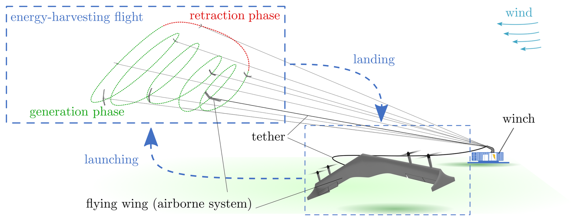
Figure 1General working principles and problem formulation of launching and landing for a flying wing AWES in the ground-gen configuration.
Figure 1 illustrates the flying wing airborne wind energy system (AWES) and its working principle when configured as a ground power generation (ground-gen) airborne wind energy system; it consists of at least one airborne system that flies in winds while tethered to a winch on the ground. For this configuration, the energy-harvesting flight comprises two alternating phases: power generation and retraction. During the energy generation phase, aerodynamic forces build up on the wing of the airborne system. In this lift-borne operation, the aerodynamic forces exerted on the wing exceed the force of gravity, allowing the system to remain airborne and pull on the tether. At the winch, this pull causes the tether to unwind from a drum, driving an electric generator. When the airborne system reaches the maximum allowable tether length, it exits the generation phase and enters the retraction phase. During this phase, the airborne system returns to its initial position while the winch retracts the tether. After that, the generation phase commences anew. As an alternative to the ground-gen AWESs, the flying airborne system can perform power generation directly. For such flying power generation (fly-gen) AWESs, specialized turbines are employed along the wing to generate electricity on board, and tethers with integrated electric cables are used to transmit the energy to the ground (Ahrens et al., 2013).
Regardless of the AWE type, one particular operational challenge is the launching and landing of the airborne system. Due to the unique flight characteristics of flying wings, these phases require specific considerations regarding the flight dynamic characteristics of flying wings and the attached tether. To give a brief understanding of the general challenge involved in the these phases, the following presents an overview of launching and landing concepts implemented in the AWE industry before presenting the paper's objective and structure.
1.1 Principle and implementations by industry
A collapsed soft-wing kite tethered to the ground can effectively demonstrate the launch principle of an AWES. When light wind strikes the kite's leading edge, the airflow gradually inflates it, forming its airfoil. This inflation enables the kite to generate lift, which depends on its aerodynamic properties and the wind speed. Once the generated lift counteracts the kite's weight, it rises into the air. Similarly, the landing process requires reducing the generated lift, allowing the system to descend safely. In both ground-gen and fly-gen AWES configurations, the airspeed at the airborne system must be sufficient to generate the lift required to compensate for the airborne system's weight and tether force. The specific cut-in ambient wind speed, the minimum wind speed needed to sustain the airborne system and to transition to energy-harvesting flight, varies depending on the aerodynamic performance and weight of the airborne system. For example, lightweight soft-wing kites, such as the PN-14 from SkySails Power GmbH (2024) shown in Fig. 2, require only 5–6 m s−1 to inflate and generate lift sufficiently (AWEurope, 2024).
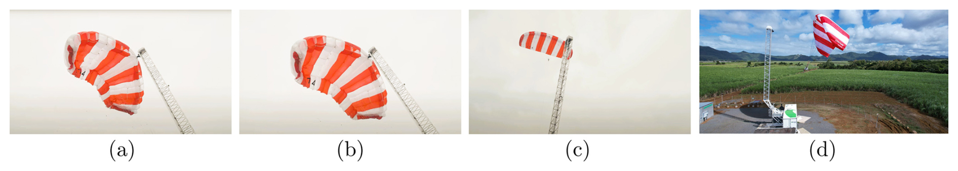
Figure 2Principle of launching for a soft-wing kite AWES from SkySails Power GmbH (2024) during launch. (a) Deflated kite, (b) inflating kite, (c) airborne kite, and (d) overview of the system. Photos from SkySails Group (2024) and Sánchez-Arriaga et al. (2024, p. 47).
Besides these soft-wing kites, various companies and academics study fixed-wing AWESs like the flying wing illustrated in Fig. 1. These fixed wings are durable and can achieve higher aerodynamic lift-to-drag ratios than soft-wing kites can due to their high-aspect-ratio wings. In addition, they can be designed with efficient aerodynamic profiles that do not deform in flight (Thedens et al., 2019). However, implementing a fixed-wing airborne system design entails increased mass, which in turn results in higher cut-in ambient winds. The company Fuchszeug B.V. (2024) (formerly Ampyx Power) is developing such fixed-wing AWESs in a ground-gen configuration. Their system, shown in Fig. 3a, has a wingspan of 12 m and is designed for a power output of 150 kW. To achieve sufficient airspeed, their airborne system accelerates on a runway, enabling launching in a similar way as conventional aircraft. However, if the goal is to design AWESs as flexible installed energy systems requiring minimal ground space, it necessitates omitting the runway. An alternative solution is a catapult-like mechanism, which addresses the issue of insufficient airspeed during launching and landing while providing the needed flexibility. This additional launching- and landing-aid system accelerates the airborne system to achieve the required airspeed for lift-borne flight even when the actual cut-in ambient wind speed is relatively low, providing greater flexibility and an extended operating range for fixed-wing AWESs. In the field of AWE, EnerKite GmbH (2024) has been a pioneer in the development of fixed-wing AWESs. They have implemented a swiveling mast, shown in Fig. 3b, to accelerate the airborne system, allowing it to achieve sufficient airspeed, generate lift, and get airborne. In addition to employing a fixed-wing configuration, Enerkite designs its airborne system as a flying wing. This configuration reduces the airborne system to a single wing without a tail, which allows for an increase in its aerodynamic performance and thus can potentially improve the overall AWES performance (Martinez-Val, 2007; Liang et al., 2017; Wohlfahrt and Nickel, 1990).
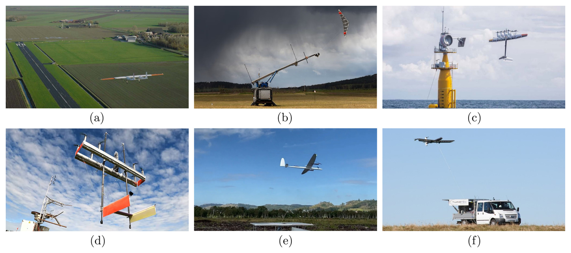
Figure 3Representative AWESs implemented by the industry: (a) Fuchszeug B.V. (2024), (b) EnerKite GmbH (2024), (c) Makani Technologies LLC (2024), (d) KiteKRAFT GmbH (2024), (e) Kitemill AS (2024), and (f) TwingTec (2024). Photos from Sánchez-Arriaga et al. (2024, p. 83), Bartel andEnerKite (2024), Schmehl and Tulloch (2019, p. 29), Kitekraft (2023), Kitemill AS (2023), and TwingTech (2018).
Conversely, the objective can be to design a fixed-wing AWES, eliminate a launch catapult mechanism, and avoid a runway, allowing the airborne system to operate more independently. In this case, the airborne system must be equipped with propulsion units and can be configured as a tail sitter, providing the vertical takeoff and landing (VTOL) ability in an upright position with the nose pointing upward (Liang et al., 2017; Ritz and D'Andrea, 2017). Based on this propeller-borne operation, referred to as thrust-borne flight, the airborne system can adjust the thrust direction to accelerate until the airspeed around the wing generates lift. As airspeed and lift continue to increase, the airborne system transitions to lift-borne flight. Full lift-borne flight is achieved when the generated lift balances the gravitational load and all other loading forces. In the field of fly-gen AWESs, the former company Makani Technologies LLC (2024) has historically held a prominent position. Their M600, shown in Fig. 3c, features a tail-sitter-like design. However, the M600 is not designed as a flying wing, as it has a tail attached to the wing. It was the subject of extensive testing, even in offshore conditions, and was the largest-ever AWES built until today. After the dissolution of the company in 2020, all technical studies were made publicly available online (Makani Technologies LLC, 2020a). As detailed in the technical report from Makani Technologies LLC (2020b), the M600 was anticipated to have a cut-in ambient wind speed of approximately 5–6 m s−1, comparable to the operational flexibility of the SkySails PN-14. In order to stabilize the longitudinal motion of the M600 while facing downwind, differential thrust was used for vertical operation, allowing the system to take off and land with the tether stretched. During this vertical flight phase, the thrust from the airborne system actively controlled the tether tension. From there, the tether was unwound to reach the desired tether length for energy-harvesting flight while the airborne system flew downwind. Subsequently, it accelerated upward to enter crosswind flight with a circular flight path. For the transition back to the ground, the M600 decelerated when the system was in the upward motion of the circular path, leaving the crosswind flight. It then hovered back to the ground station. In recent years, the company KiteKRAFT GmbH (2024), with their current AWES prototype shown in Fig. 3d, has followed in Makani's footsteps and developed a tail sitter fly-gen AWES with a very similar concept.
Although the design approaches of these two companies provide the airborne system with a certain level of control authority, it still requires a landing platform with a unique mechanical support structure to mount it on the ground. Alternatively, designs from companies such as Kitemill AS (2024) and TwingTec (2024), shown in Fig. 3e and f, have airborne systems configured as quad-planes, also providing VTOL capabilities and requiring only a smooth platform for takeoff and landing. In addition, the airborne systems can detach from the tether and fly independently of the winch, delivering increased system flexibility. In terms of deployment in an AWE wind farm, airborne systems can operate independently from a central maintenance station. For these quad-plane AWESs, a multi-copter mode first brings the airborne system downwind (Rapp and Schmehl, 2018). Once the AWES reaches a desired tether length, the airborne system is accelerated by rapid tether retraction controlled by the winch. When it reaches the minimum airspeed for lift-borne operation, the VTOL controller fades out, and guidance for the energy-harvesting flight is activated. A full technical report can be found in Houle and Luchsinger (2021) for more information on these quad-plane AWESs.
1.2 Objective and structure of paper
In terms of improved overall AWES performance, the combination of a flying wing airborne system, as pursued by EnerKite, with the ability to take off and land independently and under propulsion, as envisioned by Makani, KiteKRAFT, Kitemill, or TwingTech, is promising. This paper investigates such a flying wing AWES with VTOL capabilities, as illustrated in Fig. 1. It focuses on developing suitable guidance for launching and landing this specific flying wing AWES, while considering the specific flight characteristics of this type of airborne system. In contrast to the airborne systems designed by Makani or KiteKRAFT, the flying wing considered does not incorporate a horizontal stabilizer. Furthermore, unlike the quad-plane airborne systems developed by Kitemill and TwingTech, the flying wing does not incorporate propulsion units with an offset to the wing plane that could provide additional pitch motion control with differential thrust. Therefore, the configuration of the airborne system designed as a flying wing, driven by aerodynamic performance for lift-borne flight, results in high sensitivity and limited controllability concerning airspeed perpendicular to the wing, particularly during vertical flight (Fuest et al., 2021b). In addition to these flight mechanical challenges, the constraints imposed by the tether must be considered within the guidance design.
The following (Sect. 2) presents a guidance concept for launching and landing. Based on this, a trim analysis is performed, and the guidance concept is analyzed for specific operation parameters and wind speeds to identify limits (Sect. 3). This allows for the design of a guidance controller in Sect. 4. Section 5 presents and discusses results for a model in a loop simulation with the controller developed here, a representative wind field, and corresponding operation parameters. Finally, Sect. 6 gives this work's conclusion and outlook.
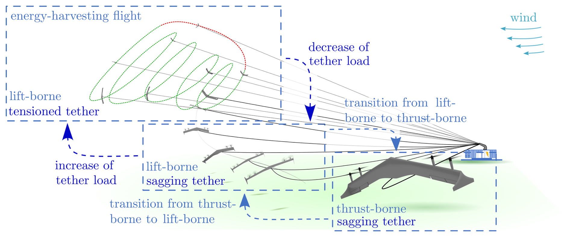
Figure 4Decomposition of launching and landing of flying wing AWESs into partial phases (shown for the ground-gen configuration).
The launching and landing of the flying wing AWES can be divided into a transition from thrust- to lift-borne flight and back but also into phases of increasing and decreasing the tether load (see Fig. 4). In an initial control concept that can facilitate the first testing of this flying wing AWES, the winch remains passive, effectively representing the tether's anchor point on the ground. However, when controlling the tether force through the flying wing, the minimum phase characteristic present forms a primary challenge. During hover flight, the flying wing can only achieve tether force control through horizontal acceleration control, which is linked to attitude control, especially pitch. However, a corresponding change in pitch attitude initially results in a short-term horizontal velocity opposite to that of the acceleration commanded and the direction of the tether force. This phenomenon was also observed by Makani Technologies LLC (2020b) during vertical tethered downwind flight. It is more pronounced, as the pitch control of a flying wing in hover flight is relatively slow compared to the other attitude controls. In addition, through the non-linear constraint and the relatively high tether stiffness, the control of the tether force in this flight state is further challenged. In this context, increasing the tether load is preferably performed during lift-borne flight to reduce the overall system complexity, minimize the required thrust, reduce the minimum phase characteristic, and remain in flight states less sensitive to disturbances. The tensioning of the tether can be achieved by increasing the turn radius through the roll motion of the airborne system. Nevertheless, it is important to note that a sudden transition from sagging to stretching can result in force peaks. Still, these can lead to critical flight states (Duda et al., 2022; Eijkelhof and Schmehl, 2022). However, as the lift-borne flight for such a flying wing is least sensitive to perturbations (Fuest et al., 2021b), tensioning the tether in this flight phase is desirable. Considering the tether as a nonlinear constraint, keeping it sagging during the transition from thrust- to lift-borne flight is preferable. Therefore, the tether's nonlinear effect on the flying wing's motion can be kept small during this phase of the launching and landing. To achieve this, the tether length ratio , where lt is the tether length, and Rt is the direct distance from the flying wing to the winch, must exceed 1 during these phases. This condition reduces the sensitivity of the spring tension (Duda et al., 2022) during the transition from thrust-borne to lift-borne flight and vice versa. By ensuring that the tether remains sagging throughout these transitions and by subsequently considering the stretching of the tether in a lift-borne flight only, the complexity of the control can be reduced.
Considering a flying wing, the transition from thrust- to lift-borne flight and vice versa can typically be achieved through a pure pitch transition. This is accomplished through the implementation of control architecture that utilizes switching logic to select between a thrust-borne and a lift-borne flight controller (Stone et al., 2008; Jung et al., 2013; Hochstenbach et al., 2015; Wang et al., 2015). Nevertheless, the flight regime for a pure pitch transition of a flying wing as an airborne system is constrained, particularly at lower airspeeds during vertical flight (Fuest et al., 2021b). The control system's complexity is further augmented when the transition with the tether attached to the airborne system is taken into account. Given that the tether is affixed to the bottom of the airborne system, it is essential to ensure that this side is oriented approximately towards the winch to prevent tether entanglement with the airborne system. In this context, a controllable pure pitch transition is restricted to top-directed flight on a hemisphere, as illustrated in Fig. 5. The tethered airborne system performs a continuous pitch motion on this flight path while flying in the direction of the zenith. Consequently, the airborne system must transition to lift-borne flight upon reaching the zenith. This approach necessitates a single-turn transition, which presents challenges for step-by-step field testing. Furthermore, the return transition poses additional conceptual difficulties, depicting the overall complexity of achieving a pure pitch transition with a flying wing in an AWE context.
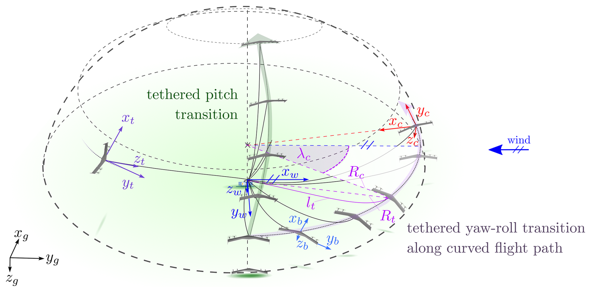
Figure 5Pitch transition vs. yaw–roll transition on a curved flight path. The figure also illustrates the coordinate systems with the subscripts g (geodetic), t (tether), w (wind), b (body-fixed), and c (cylindrical).
A multi-axial yaw–roll transition on a curved flight path around the winch can be an alternative. In its simplest form, it is executed at a fixed height, as illustrated in Fig. 5. This knife-edge-like maneuver couples lateral and longitudinal motion. When performed on the curved path, the distance to the winch can be held constant, allowing the tether to sag and minimizing its interference. Furthermore, a step-by-step test procedure can be conducted along the curved path. Considering the launching, after takeoff and the hover to the transition height, the flying wing rotates around the yaw axis to gain speed in the longitudinal direction of the wing (yaw-dominant transition phase). Then, when the airspeed is sufficient, the airborne system rotates about its roll axis (roll-dominant transition). The lift force builds up, and the airborne system transitions to lift-borne flight. When the transition is performed on a curved path, the airborne system can directly control the distance to the winch by varying the turning radius. This means no further winch control of the tether length is required during this operation phase, and the system's overall complexity is reduced. Once a threshold tether force is exceeded, the guidance can consider a tether force control phase and navigate on the sphere spanned by the tether. This forms a base to enter the energy-harvesting flight. To leave the energy-harvesting flight and perform a landing, the tether load is reduced by decreasing the turn radius via roll motion. The subsequent transition back to thrust-borne flight can be performed via a roll–yaw motion. Eventually, the flying wing can decelerate and perform a landing.
To describe the curved flight path, the cylindrical coordinate system subscript c shown in Fig. 5 can be used. There, xc points to the center of the path curvature, zc points to the ground, and yc is tangential to the curved path. In addition, the wind position angle λc and the radius of curvature Rc allow the description of the position of the airborne system in the plane of the flight path. In addition, Fig. 5 also illustrates the geodetic (subscript g), body-fixed (subscript b), and wind (subscript w) coordinate systems. This wind coordinate system is defined by xw pointing upwind. In Fuest et al. (2021b), a trim analysis for a flying wing is conducted, concluding that when in thrust-borne hover flight, the wing plane must be aligned with the direction of airspeed to ensure controllability. At the beginning of the launching phase and the end of the landing phase, the ground speed is small, so the lift plane of the flying wing must align with the direction of the wind to consider this. Thus, for both phases, a VTOL zone is considered at an approximate wind position angle of λc=90° and a fixed radius Rc. This also ensures that sufficient lift is generated in the shortest possible time. For the tether force control phase, a tether coordinate system is considered according to Nelson (2019). As shown in Fig. 5, zt points in the direction of the winch, xt points towards the zenith, and yt results in a right-handed coordinate system. In addition, the geodetic coordinate system serves as the basic reference frame, with the xg axis pointing north, the yg axis pointing east, and the zg axis pointing to the ground. As shown in Fig. 5, the body coordinate system attached to the flying wing moves with it, providing a local reference frame for describing its motion and orientation. This system originates at the center of mass of the wing, with the xb axis aligned with the nose (longitudinal axis), the yb axis pointing towards the right winglet (top view), and the zb axis pointing downwards. Transformations between the geodetic and body coordinate systems are described by Euler angles: roll (ϕ), pitch (θ), and yaw (ψ). In Fuest et al. (2023), we presented a preliminary trim analysis of the proposed multi-axial yaw–roll transition along a straight flight path without the tether. However, a more comprehensive trim analysis is required when considering centrifugal loads due to a curved flight path and a constant wind field. In the following, we analyze and examine the system for the guidance concept introduced in this paper, including trim computations for transitions along curved flight paths with varying wind speeds.
The following analysis is based on a representative small-scale flying wing demonstrator. A model was developed to identify and analyze controllable flight states at varying wind speeds and operational parameters. In consideration of the proposed guidance concept for launching and landing, the guidance limits of the flying wing AWES can be identified.
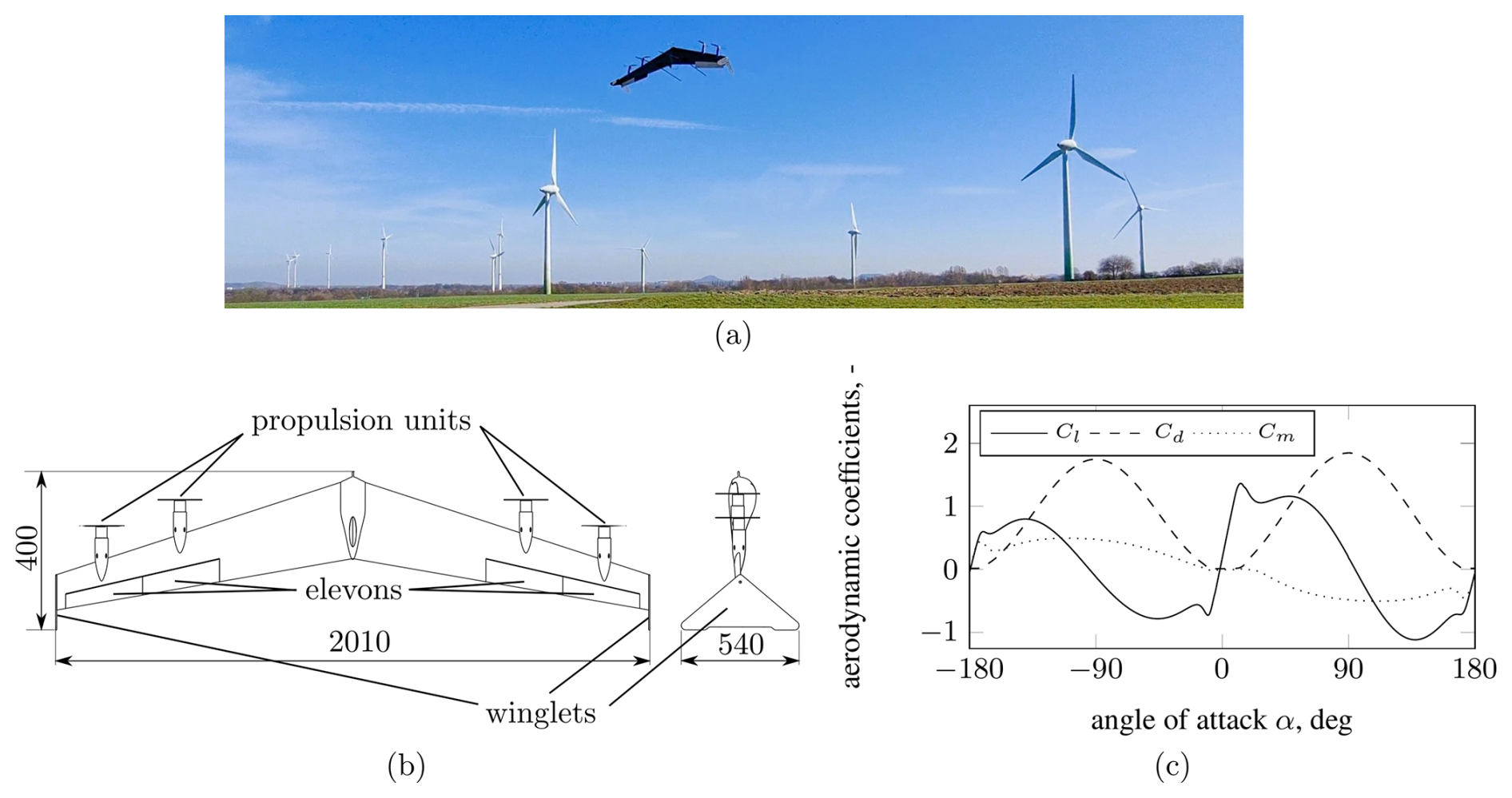
Figure 6Flying wing demonstrator. (a) Demonstrator in a field test, (b) a sketch of the demonstrator and dimensions in mm, and (c) the polar of the HS 3.4/12.0B airfoil.
3.1 Demonstrator
The airborne system of the AWES under consideration in this study is a small-scale flying wing with a mass of 3.5 kg, depicted in detail in Fig. 6. As shown, this flying wing demonstrator has a wingspan of about 2 m and is equipped with four propulsion units, two on either side of the wing, situated within the wing plane. Additionally, it is configured with two elevons on each side, positioned within the wake flow of the propulsion units. A detailed description of these controls' general working principles and operational characteristics can be found in Fuest et al. (2021b). As also shown in Fig. 6, winglets are attached to the wing tips of the flying wing. These allow this flying wing to stand upright on the ground as a tail sitter and act as vertical stabilizers in lift-borne flight. The wing is designed with the HS 3.4/12.0B airfoil, which is characterized by a large relative chamber of 3.4 % and relative thickness of 12.0 % chord length, allowing high lift coefficients in lift-borne flight and very small pitch moments. In contrast to most other flying wing tail sitters investigated by academia in recent years (Li et al., 2018; Tal et al., 2023; Smeur et al., 2020), the aspect ratio of the this flying wing is up to 2 times higher, allowing a reduction in the induced drag and improvement in the potential performance of the AWES. Overall this small-scale demonstrator is intended to be comparable to future demonstrators designed primarily for the energy-harvesting flight phase and thus driven by aerodynamic efficiency. For autonomous operation, the flying wing is equipped with a flight computer and various sensors, such as an inertial measurement unit, a satellite navigation receiver, a wind vane, and a servo-controlled pitot tube to estimate flight conditions such as airspeed. In addition, the flying wing is equipped with a load cell to measure the tether force. This load cell is integrated into the tether anchor point of the flying wing, which is located on the underside of the wing and at the center of gravity. The tether is of the Dyneema type, known for its high strength and low weight. It has a diameter of 1 mm and a length between 50 and 85 m. Regarding the guidance concept for launching and landing, presented here, the winch of the AWES is considered an anchor point for the tether on the ground. Consequently, the winch is not addressed further in this analysis, and the tether length is treated as fixed throughout the launching and landing process. This simplifies the overall complexity and facilitates field testing.
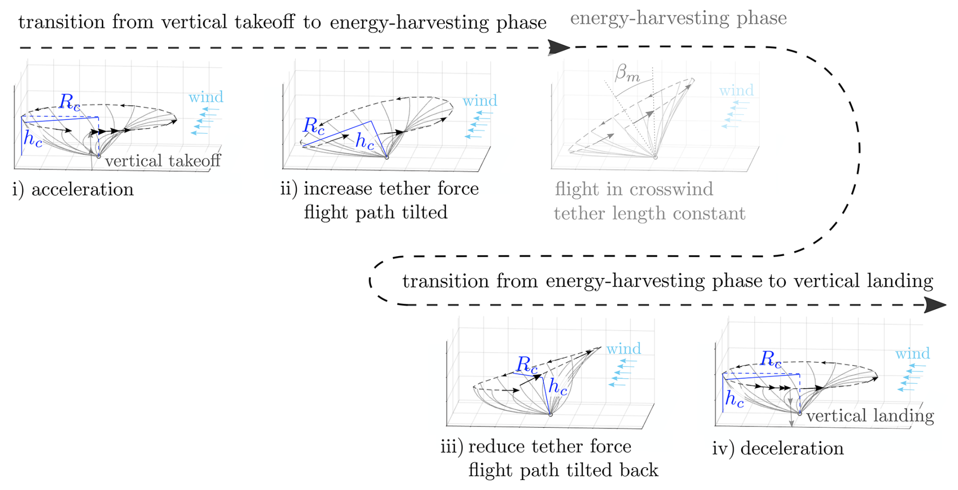
Figure 7Defined transition phases considered in the trim analysis (radius Rc and height h are given as specific guidance parameters).
3.2 Model
The flying wing is modeled as a rigid body with mass m and 6 degrees of freedom. The translational motion can be described by Eq. (1). Here, [u v w]T represents the translational velocity and [p q r]T the rotational velocity. In addition to the inertia loads, the thrust is represented by T pointing in the body-fixed xb direction. The aerodynamic load is represented in the aerodynamic coordinate system (subscript a) by lift L as well as by drag Dx and Dy. This aerodynamic coordinate system is formulated according to Brockhaus (2010). The aerodynamic force vector is transformed into the body-fixed system using the coordinate transformation matrix Mba. Similarly, gravitational and tether force are transformed into the body-fixed coordinate system using Mbg and Mbt.
The complete angular motion can be described by Eq. (2), where are the body-fixed rotational accelerations, I is the inertia tensor, and [Mx My Mz]T include all external moments. The external moments are those generated by the thrust, the deflection of the elevons, and the airspeed on the wing. The tether force is assumed to act on the center of mass.
In order to model the aerodynamics of the flying wing, a semi-analytical element-based nonlinear approach according to Hartmann (2017) is applied. In this approach, the wing is decomposed into a discrete number of elements with similar aerodynamic properties, considering the influence of the elevon deflection and the increased airflow on the wing elements in the slipstream of the propellers. The aerodynamic and gravitational forces and moments are summed for all wing elements. In order to appropriately model the tether and keep it suitable for modeling in the loop simulations, a model similar to that of Williams (2017) is used. This model allows the total stiffness of the tether to be modeled, while maintaining a sufficiently large simulation time step for fast computations. It considers aerodynamic, gravitational, and inertial loads acting on the tether. The quasi-static approach uses a shooting process to calculate the stationary shape and the corresponding tensile forces in the entire tether, starting at the winch and progressing to the flying wing. In the model in the loop simulation performed to validate the controller, the complete set of equations of motion given in Eqs. (1) and (2) is solved for each simulation time step. As mentioned in the guidance section, this work assumes that the tether length remains constant throughout the launching and landing phases considered. Thus, no winch dynamics is considered.
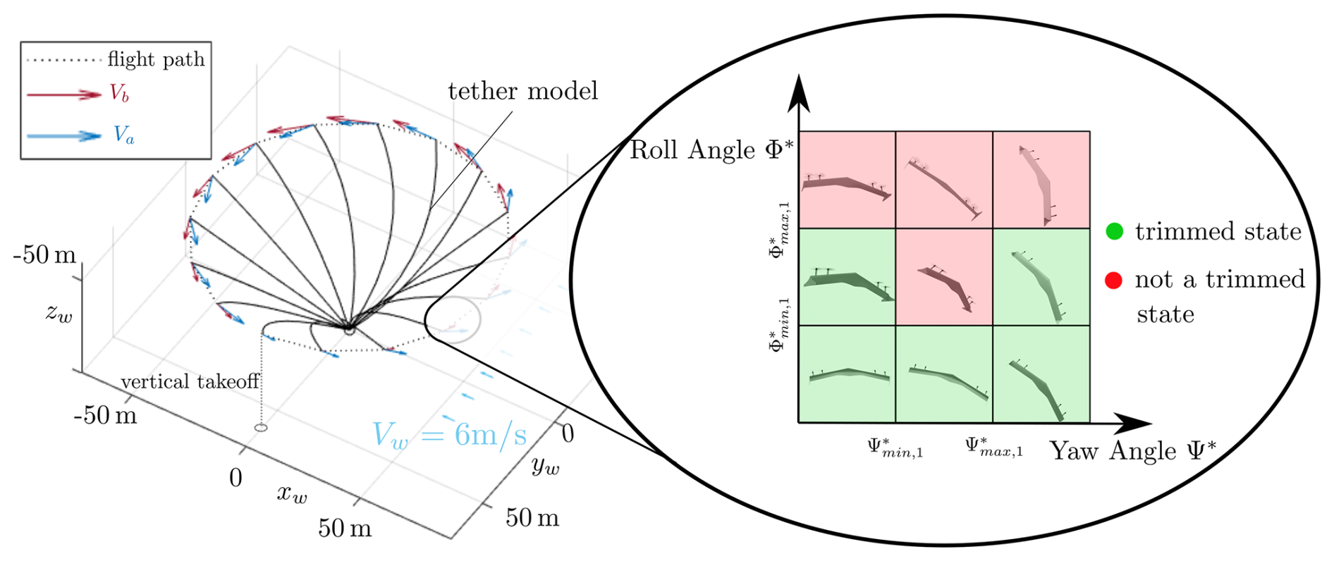
Figure 8Aerodynamic and body velocities for a curved flight path (phase (i)), as well as the attitude variation grid for trim state computation at path point n=4 (λc=68°).
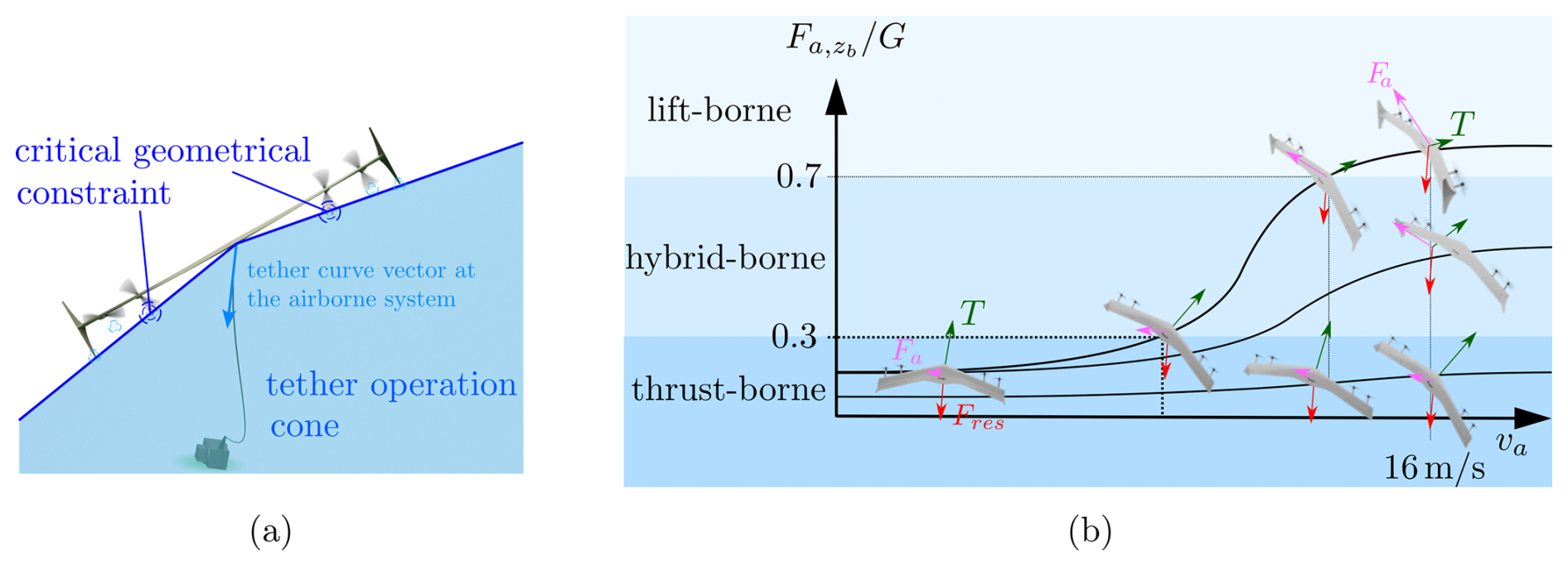
Figure 9Tether operation cone (a) and the definition of flight state types: lift-, hybrid-, and thrust-borne operation (b).
3.3 Trim analysis
A trim analysis is performed for the guidance concept presented. Here, a trim state is generally controllable when all forces and moments are balanced and the controls are within their limits. For such a trim analysis of the launching and landing, we propose a parameterized guidance path divided into multiple phases, as shown in Fig. 7. Based on this parameterized trim analysis, a controllable flight path can be identified for different wind conditions. To better classify the phases within the launching and landing operation, the tilted flight path for energy-harvesting crosswind flight is also shown in Fig. 7 between phase (ii) and phase (iii). However, it is not examined further. As illustrated in the figure, all phases have in common the fact that they start at wind position angle λc=90° and cover 360°. In the following list, the main characteristics of these four phases are given:
- (i)
a curved flight path with a turn radius Rc at fixed height hc, starting in the VTOL zone and accelerating in the upwind direction at 1 m s−2 up to 16 m s−1 in airspeed;
- (ii)
a curved flight path with constant airspeed, increasing the turn radius until the tether is tensioned and tilting the flight path to the mean elevation angle βm=10°;
- (iii)
a curved flight path with constant airspeed, decreasing the turn radius until the tether is sagging at k=1.05 again and tilting the flight path back to a mean elevation angle of zero;
- (iv)
a curved flight path with a turn radius Rc at fixed height hc and deceleration at 1 m s−2 until the VTOL zone is reached.
Each path is divided into n equally spaced discrete path points for an analysis of these four flight path phases. Based on a prior convergence study, the following analysis is performed for n=16 path points. This provides sufficient resolution of the flight path, while keeping the computational effort reasonable for a comprehensive trim analysis. The aerodynamic velocity Va∈ℝ3 at each discrete path point depends on the body velocity vector Vb∈ℝ3 and the wind vector Vw∈ℝ3, as given in Eq. (3):
As shown in Fig. 8, we assume that the wind is constant in magnitude and direction. A set of trimmed flight states with associated control settings can be determined based on the aerodynamic velocity at each path point. Following the work on the straight yaw–roll transition in Fuest et al. (2023), we seek to identify a set of trimmed flight states for each path point. Considering the motion on the curved flight path, each path point has a specific aerodynamic velocity. In order to evaluate the trim characteristics for different attitudes, the attitude of the flying wing is varied within the limits of a predefined grid of different attitude variations. This allows the determination of multiple attitudes that fulfill the trim condition for a path point that is considered. These trimmed states are marked green, while the others are red in the grid on the right side of Fig. 8. In addition to the general trim conditions, the trimmed flight states must satisfy the following constraints for operation within an AWES.
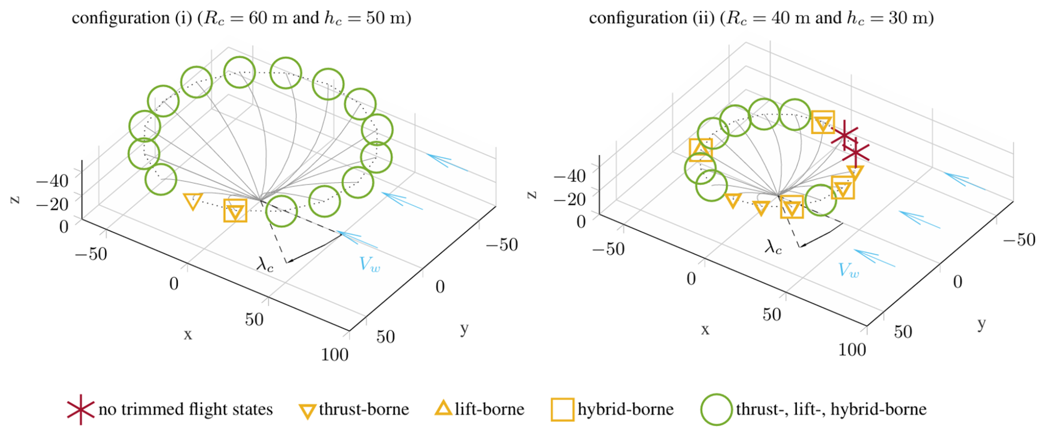
Figure 10Results from trim computation for a circular flight path with accelerating airspeed up to 16 m s−1, with an assumed wind speed of 6 m s−1. Only the turn radius Rc and transition height h are varied. The tether length ratio is the same ().
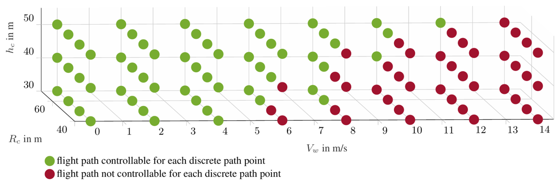
Figure 11Resulting flight path trim computations for a set of assumed wind speeds Vw and variations in turn radius Rc; transition heights h are divided into those that are controllable and those that are not controllable.
-
The thrust and elevon commands of the flying wing must be within the corresponding actuator limits. For the small-scale demonstrator considered, the maximum thrust per engine is set to 18 N, and the maximum elevon deflection is set to 30° in each direction.
-
Since the flying wing is intended to operate within an AWES, the flight attitude must ensure that the tether can hang freely from the attachment point of the flying wing to the winch. This condition is considered with a tether operation cone, shown on the left side in Fig. 9. This cone is geometrically defined by the distance vector of the tether attachment point at the center of gravity and the position of the inner rotor tips. These points form the boundary of this tether operation cone. Other exposed geometric points such as the winglet edges or the rotor tips of the outer propulsion systems are outside this critical cone. Consequently, it is imperative to ensure that the tether curve at the flying wing remains within the designated operating cone to avert any potential tangling of the tether with the flying wing's components.
-
For any trim state of an observed path point, the flying wing must be able to reach at least one new trim state for the following path point. This means that the required rotational rate of the flying wing must be within the dynamic limits of the flying wing. The maximum pitch, roll, and yaw rates for the flying wing demonstrator are set to 30° s−1.
With these additional constraints, the trimmed flight states can be computed for each path point. To identify flight states as either thrust- or lift-borne, the transition ratio, which is the ratio of the aerodynamic force to the gravitational force, is considered. We define a transition ratio of 0–0.3 corresponding to thrust-borne states, a ratio of 0.3–0.7 to hybrid-borne states, and ratio greater than 0.7 to a lift-borne state (see the right side of Fig. 9). This allows the path points to be associated with the flight state characteristics that are occurring: lift-borne, hybrid-borne, or thrust-borne states; a combination of these three; or a non-trimmed state, i.e., an uncontrollable flight state. Figure 10 shows the results of two example trim computations corresponding to the transition operation phase (i). Here, the wind speed is assumed to be 6 m s−1. For the left configuration (i), the radius Rc is set to 60 m, the height hc to 50 m, and the tether length ratio to k=1.05. After a vertical start at λc=90°, the flying wing accelerates upwind in a counterclockwise direction. For the first few path points from λc=90° to λc=60°, the emerging airspeed remains below 12 m s−1, so the trimmed flight states have transition ratios below 0.7, meaning that they are thrust- or hybrid-borne states. Moving counterclockwise, the path points from there include states that can be trimmed lift-, hybrid-, and thrust-borne states. These path points are shown as green circles and represent all three types of flight states. Considering the same launching phase for a smaller radius of Rc=40 m and at a lower height hc=30 m, as shown in the second configuration (ii) on the right side of Fig. 10, the aerodynamic velocity and the inertial loads along the flight path change. Due to the resulting change in the direction of the tether force at the flying wing, two path points in the range λc=270°–290° cannot be trimmed. In this region, the centrifugal load is higher than average along the flight path as the body speed is increased to maintain a constant airspeed in this downwind region. The reduced turn radius Rc for this configuration (ii) further increases the centrifugal load. Thus, the flying wing must reach a height that allows it to point the thrust vector more towards the center of the circular flight path to meet the trim condition. The resulting flight states satisfy the general trim condition but not the extended trim condition, considering the additional AWE-specific constraints that ensure that the tether is within the tether operation cone. Therefore, no controlled states can be found for these two path points. The other yellow path points have flight states that satisfy the extended trim condition. However, the corresponding flight states are only trimmed thrust-, hybrid-, or lift-borne states.
This comparison shows the importance of analyzing this flying wing AWES with specific operating parameters to ensure that the intended operation is controllable. The radius Rc and height hc for the parameterized guidance paths presented here could be identified as critical parameters. These two guidance parameters are varied for a discrete set of wind speeds ranging from 0 to 14 m s−1. The results are plotted in Fig. 11. The parameter combinations that lead to trim computations in which all path points for all four phases considered have trimmed flight states and include the intended flight state are marked in green. This means, for example, that for phase (i), lift-borne flight states can be achieved when the airspeed reaches 16 m s−1. On the other hand, for phase (iv), considering the transition back to vertical thrust-borne flight before a vertical landing, a thrust-borne trim state exists in the VTOL zone (λc=90°). All those parameter combinations with path points that cannot be trimmed or do not reach the desired flight state in the phase considered are marked red. The results shown in Fig. 11 overlay the trim computation results corresponding to all four phases. Consistent with the analysis for the two single configurations shown in Fig. 10, most of the critical parameter combinations marked red in Fig. 11 are due to an increase in centrifugal loads. As it is assumed that for the guidance concept presented here the tether must remain sagging during phase (i) and phase (iv) and that the tether must remain within the tether operating cone, the controllability along the flight path is limited. The area marked in green can also be interpreted as the flight regime of this flying wing AWES concerning the guidance approach considered, different wind speeds Vw, and the operating parameters radius Rc and height hc. Ultimately, this allows us to map a measured wind speed to specific guidance control commands hc and Rc, ensuring controllable launching and landing.
This section presents the underlying overall control architecture before giving a more detailed design overview of the novel guidance controller that considers the guidance concept presented in this paper and the results from the trim analysis.
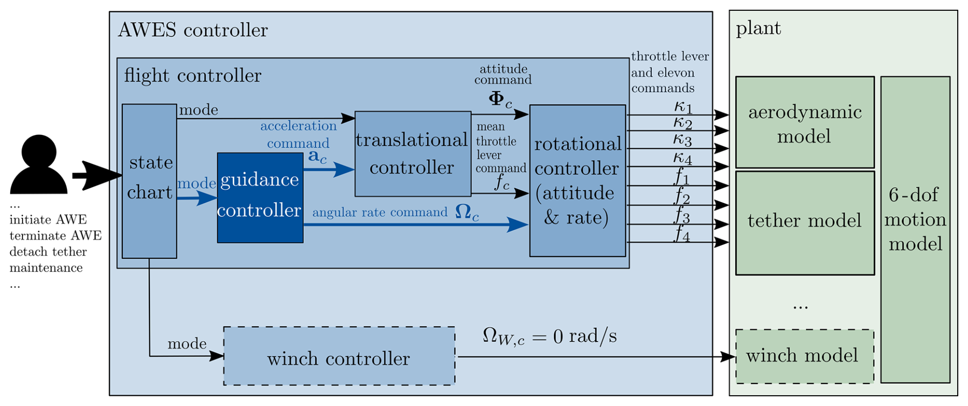
4.1 Overall control architecture
The overall control architecture of the flying wing AWES is presented in Fig. 12. As shown, the enhanced interface allows a user to initiate or terminate the operation. Additionally, the user can access different operational modes, such as tether detachment and independent, untethered operation of the flying wing, for example, to perform a flight to a designated maintenance station. For these winch-independent operations, the flight controller must enable full control of the translational and rotational motion using only the onboard actuators of the flying wing. When the flying wing operates as part of the AWES, it must also establish a set-point control for the winch, analogous to specifying a reel-in or reel-out velocity for the tether. In this mode, the flying wing controls the tether force and high-frequency dynamics, while the winch is responsible solely for the tether velocity. Thus, the winch controller functions as a subordinate controller, receiving its control mode from the flight controller. Following the guidance concept presented here in its simplest form, the winch control is inactive () during launching and landing. The flight controller considered here is cascaded into guidance, translational, and rotational controllers (see Fig. 12). Above these sub-controllers, a state chart determines the current mode depending on the operator inputs. As shown in Fig. 12, the rotational controller on the lowest level of the cascaded controller architecture determines the commands for the four elevons (κ1–4) and the throttle levers for the four propulsion units (f1–4) to control the flight attitude and rotational rate. The prescribed mean thrust (fc) and attitude commands (Φc) serve as inputs to this rotational controller and are outputs of the superior translational controller. In addition, the guidance controller can directly command a rotational rate (Ωc), also serving as input for the rotational controller. The entire rotational controller consists of a controller based on rotational incremental nonlinear dynamic inversion (INDI) and a subordinate linear–quadratic regulator (LQR). The LQR provides the required rotational accelerations for the INDI controller. A detailed description of this rotational controller and validating flight tests are presented in Fuest et al. (2021a). Like the rotational controller, the translational controller is based on an INDI control approach. As shown in Fig. 12, the translational controller determines the attitude Φc and mean throttle lever fc command to control the acceleration ac. The design of the controller is presented in detail in Duda et al. (2024). A peculiarity of this translational controller is that it considers the desired attitude change. This enables the flying wing to change the attitude from vertical thrust-borne flight to lift-borne flight and vice versa, while ensuring that the translational motion is controlled sufficiently.
4.2 Guidance controller
The guidance controller forms the highest cascade of the flight controller. As shown in Fig. 13, it consists of position and velocity controllers, a state chart, and a curve coordination. Depending on the guidance state chart, the controllers concerning the cylindrical coordinate system or the controllers concerning the tether coordinate system are active. In the following, these components are presented in detail.
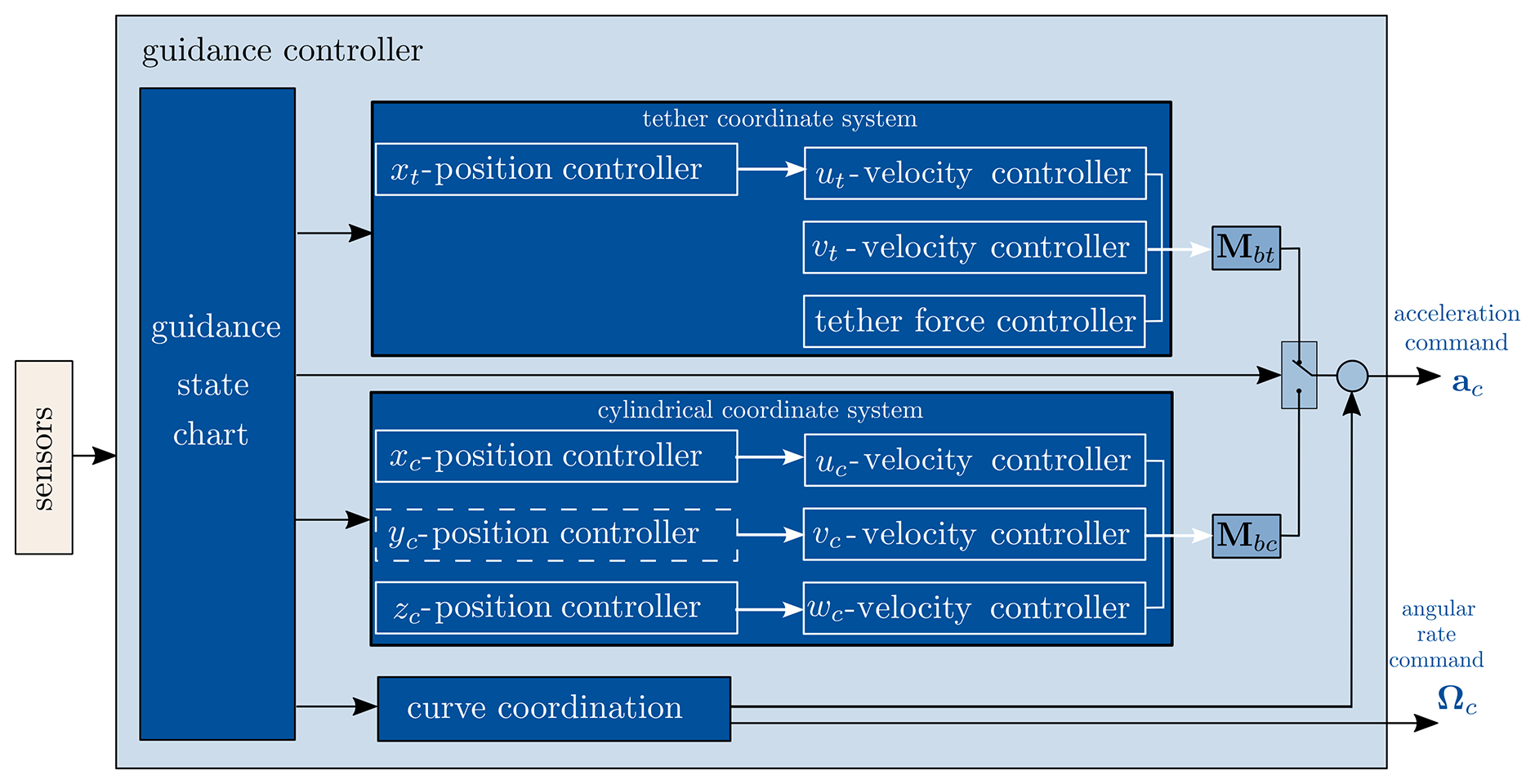
4.2.1 Velocity, position, and tether force control
The position and velocity controllers depicted in Fig. 13 are cascaded controllers. Thus, the position controller determines a velocity command based on a position deviation. The velocity controller determines a required acceleration command based on this velocity command and the actual velocity. The velocity and acceleration commands that are determined are obtained with an LQR approach. Assuming an ideal INDI controller, its transfer behavior can be expressed through its virtual actuators (Smeur et al., 2016). Regarding the translational controller, these virtual actuators' dynamics correspond to the rotational controller's dynamics and the propulsion model (Duda et al., 2024). With a linear model of these actuator dynamics, the LQR control can be designed.
Concerning the cylindrical frame of reference, this allows us to control the radius through the xc-position controller, the lateral position through the yc-position controller, and the flight path height through the zc-position controller. Based on the position deviations, these position controllers output their respective velocity commands in the cylindrical coordinate system. Except for the hover phase, the position controller in the yc direction is inactive, and a velocity command corresponding to an airspeed of, e.g., 16 m s−1 along the curved path is set. The resulting acceleration command vector in cylindrical coordinates is transformed into the body coordinate system using Mbc. Similarly, the guidance controller contains position and velocity controllers that operate within the tether coordinate system, allowing direct control of the tether force through a specifically directed acceleration. This acceleration command at,c(3), which corresponds to a scalar tether force command Ft,c and an actual tether force Ft, is expressed as follows:
Since the resulting acceleration must counteract the tether force, the force deviation is inverted and divided by the mass m of the flying wing. This calculation considers the tether force acting in the zt direction. The resulting acceleration command is subsequently transformed into body coordinates using the transformation matrix Mbt.
4.2.2 State chart
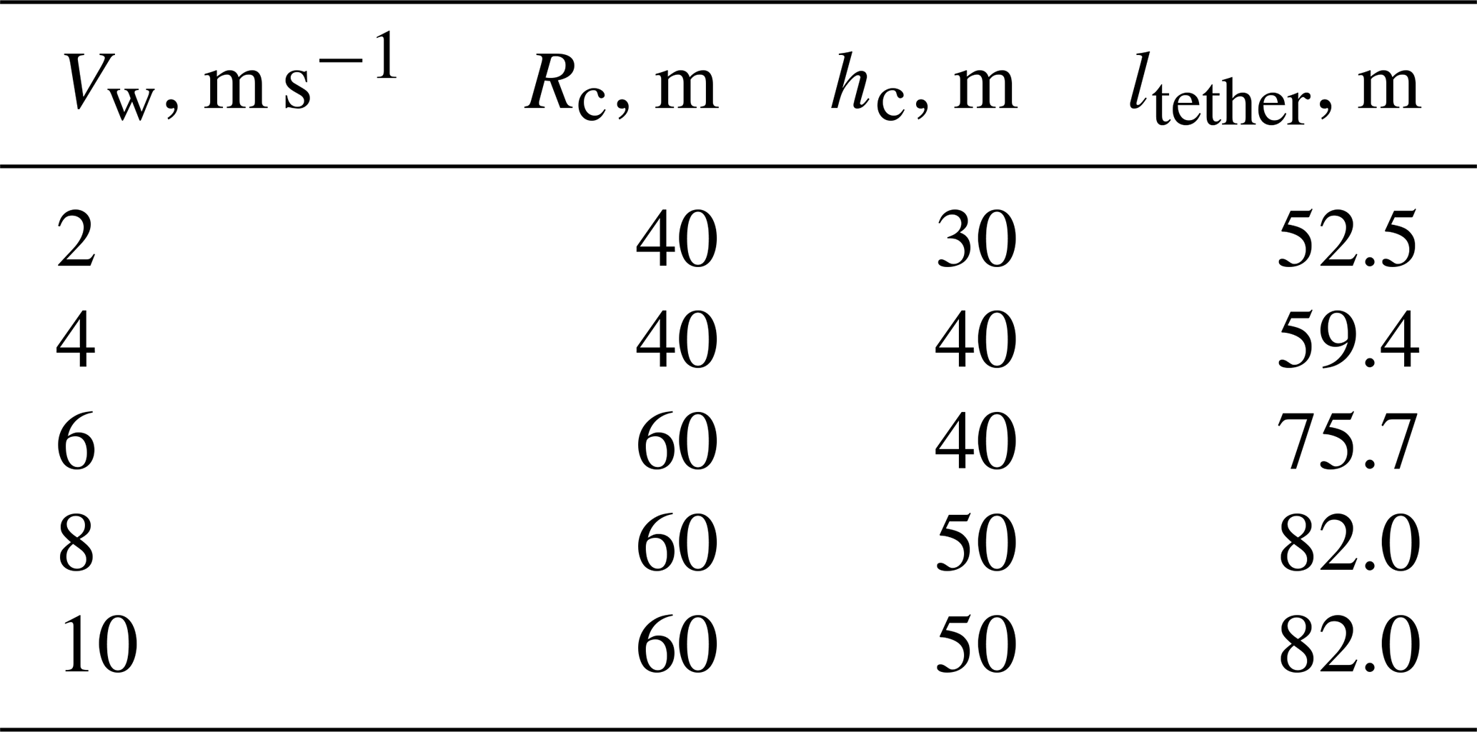
Based on the results of the trim analysis, the guidance controller uses the lookup table presented in Table 1 to specify a transition height, a path radius, and an initial tether length for a measured wind field. Accordingly, the flying wing must be placed in the resulting VTOL zone, and the required tether length must be unwound.
Table 1Lookup table for controllable operation of the tail sitter AWES. The table lists the recommended turn radius, transition height, and tether length for different prevailing wind speeds (assuming a tether length ratio of k=1.05).
Regarding the launching, the flying wing takes off in the VTOL zone and hovers to the transition height before accelerating in an upwind direction, with an active position controller in the xc and zc directions and an active vc controller. The velocity command gradually increases to an airspeed of 16 m s−1 within this mode. According to the flight regime analysis, an acceleration of 1 m s−2 is aimed at. In order to increase the tether load, the position controller in the yc direction is turned off, and only a uc command corresponding to a radial velocity of 0.2 m s−1 is set. This slowly increases the radius until the tether is stretched and loaded. Moreover, the mean elevation, which partially defines the orientation of the cylindrical coordinate system, can be changed to a value of, e.g., 10° to tilt the flight path. During the tether-loaded lift-borne flight, a specific tether force can be ordered, and the energy-harvesting flight can start.
Regarding the landing, the flying wing must reduce the tether force and return to a flight with a sagging tether by decreasing the position in the yc direction (command radial velocity of ). In order to exit the lift-borne flight state and begin the transition back to a thrust-borne one, the flying wing has to yaw and build up a slip angle before a roll transition back to thrust-borne flight can take place.
4.2.3 Curve coordination
Within this block, the rate command Ωc is computed to achieve a coordinated curve for a given turn radius Rc and body velocity Vbody:
Since the resulting virtual acceleration command from the velocity controller is based on the velocity deviations, the centrifugal acceleration from curved flight must also be considered. The compensation can be calculated as the cross product of the actual body rates and velocity:
The control concept is tested for launching and landing in a model-in-the-loop simulation environment. The simulation is performed in MATLAB Simulink. The controller runs with a sampling time of 0.005 s. In the following, a simulation for three different sections covering the phases of transition shown in Sect. 3.3 is presented and analyzed in detail. Similar to the cases analyzed in Fig. 10, a wind speed of 6 m s−1 is assumed. Following Table 1, the radius Rc is set to 60 m, and the transition height hc is set to 40 m. The simulation results for phase (i), including the curved yaw–roll transition, are presented in Fig. 14.
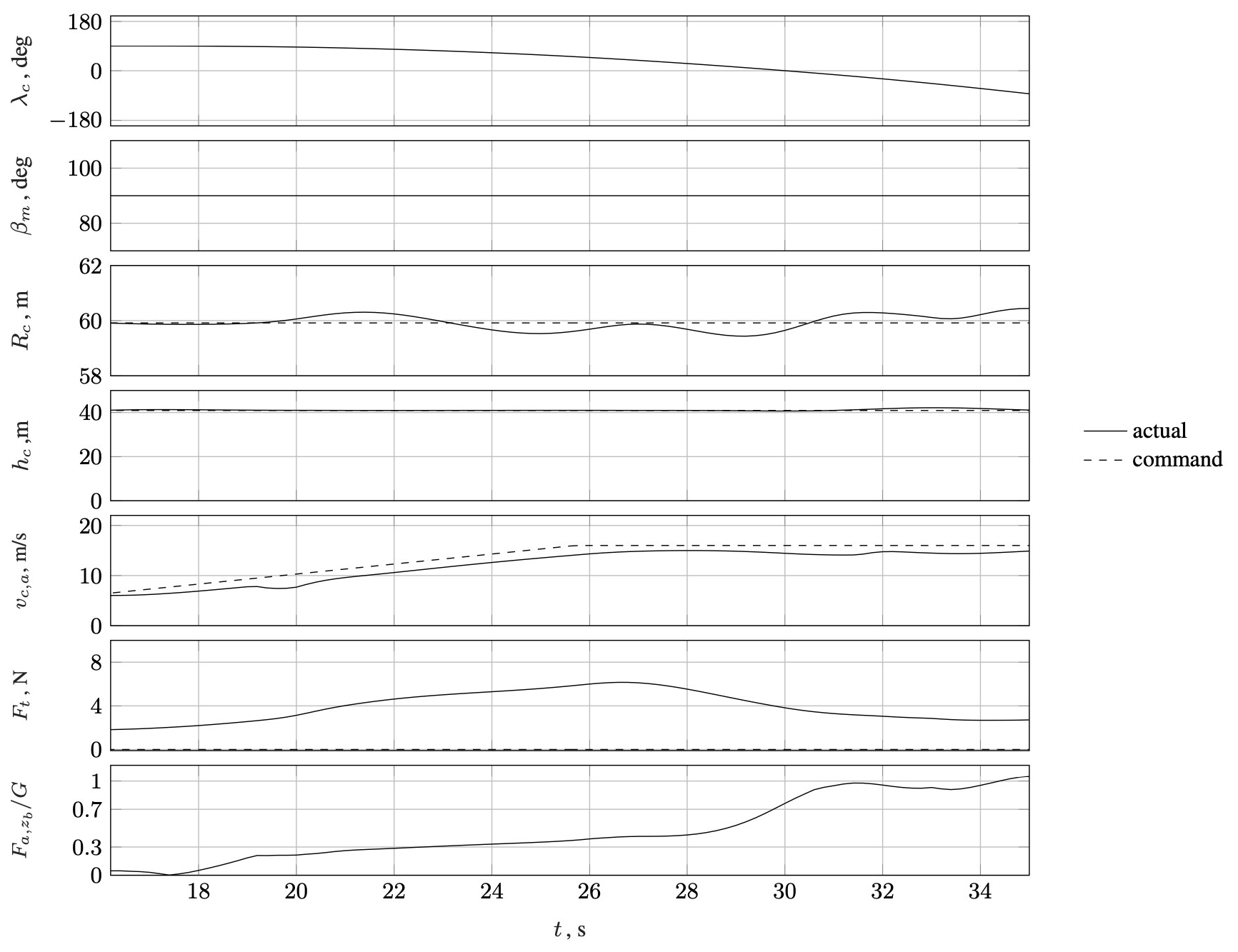
Figure 14Simulation results for the launching phase (i) (takeoff and acceleration along a curved flight path, , Rc=60 m, and hc=40 m).
As shown in the velocity plot, the scalar velocity command vc,a slowly increases, starting at 6 m s−1 (velocity of the prevailing wind field) and going up to 16 m s−1. As soon as an aerodynamic velocity of 12 m s−1 is reached, the airborne system starts to roll, and the transition ratio () increases to about 1, indicating a fully lift-borne flight condition. During this transition, the radius and height remain constant. The small increase in the tether force during this phase can be explained by increasing aerodynamic loads acting on the tether as it passes through an angular range of . During this first phase, the mean elevation is kept constant at 90°.
The results of the following 65 s of the simulation are presented in Fig. 15. As shown by a decrease in the mean elevation βm from 90 to 80°, the flight path tilts after 35 s. When the flight path is tilted, the height and radius deviate slightly more, but the deviation remains below 2 m. After a flight time of 60 s, the radius command is slowly increased until a threshold tether force of 12 N is exceeded, and the controller switches to a tether force control mode. Here, the target force is set to 20 N. As soon as the flying wing is supposed to transition back, the tether force controller is turned off, the radius and height controller are activated, and the radius is reduced again to 60 m.
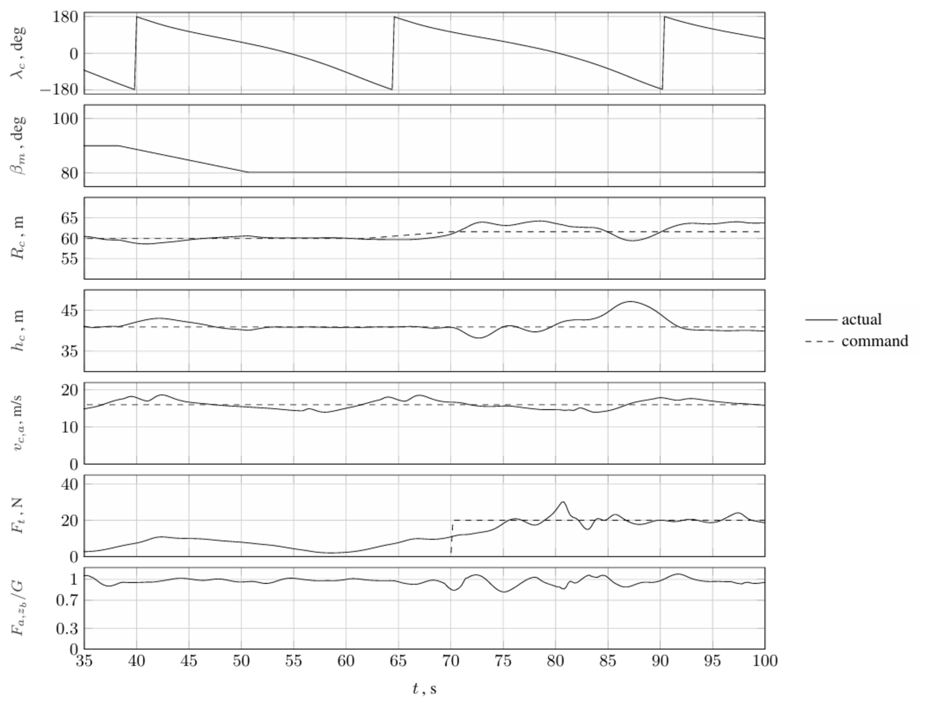
Figure 15Simulation results for the launching phase (ii) and the tether force control phase (takeoff and acceleration along a curved flight path, , Rc=60 m, and hc=40 m).
Figure 16 gives the results of the last 54 s of the simulation. As shown, at a flight time of about 110 s, the flight path begins to tilt back to 90°. When an average elevation of βm=90° is reached, the transition back to the thrust-borne flight state is initiated. For this purpose, the guidance controller commands the desired negative yaw and positive roll motion while ensuring that the radius, altitude, and velocity remain controlled. After approx. 140 s, the deceleration phase begins, and the flying wing decelerates at 1 m s−2. The deceleration begins when the flying wing passes the power zone at λc=180°. After approx. 155 s, the airborne system reaches the VTOL zone again and hovers back to the ground.
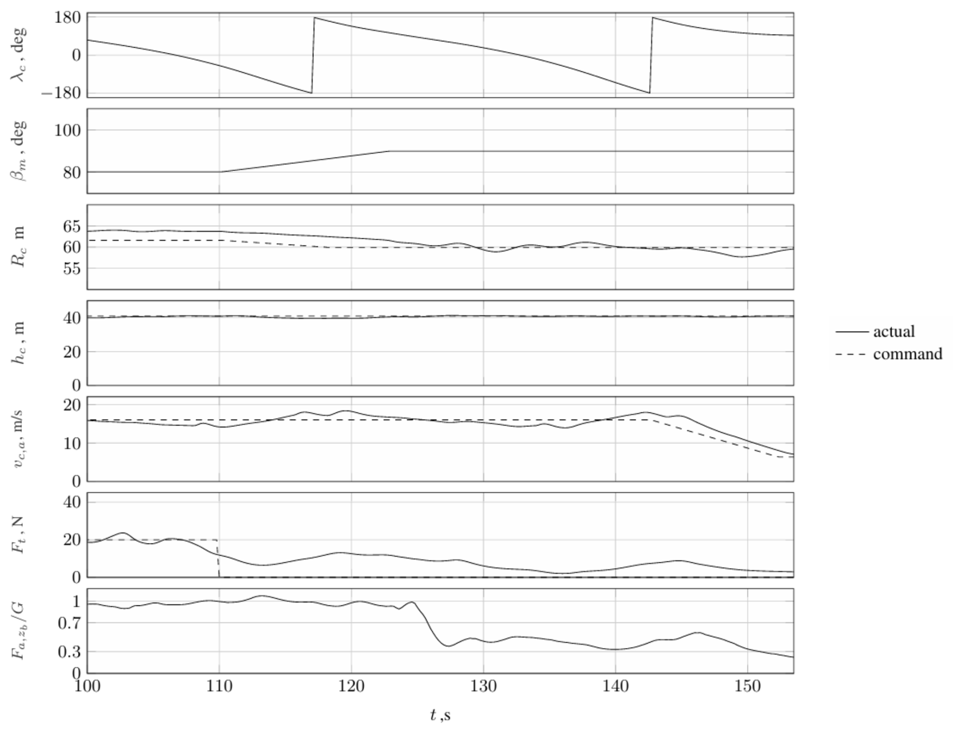
Figure 16Simulation results for the exit of the tether force control phase and the landing phase (decrease in radius, deceleration, beginning of the vertical flight back to the ground, , Rc=60 m, and hc=40 m).
Overall, the simulation shows that the control concept presented achieves the desired results. The radius and height commanded can be controlled throughout the entire acceleration and transition from thrust- to lift-borne flight, with control deviations of less than 0.8 m. The tangential aerodynamic velocity is also controllable but deviates up to 3 m s−1. This is due to the changing airspeed for a circular flight in a wind field. The flight phase from 70 to 110 s shows that a tethered crosswind flight can be achieved and exited with the guidance concept presented here. Similar to the transition from thrust- to lift-borne flight, the transition from lift-borne back to thrust-borne flight can be achieved with position deviations of less than 2 m and a velocity deviation of less than 3 m s−1.
This paper presents a guidance concept for a flying wing AWES's launching and landing phases. The limitations associated with these two operational phases are examined to develop an appropriate guidance concept for this particular AWES. We highlighted that the flight characteristics of such a VTOL-capable flying wing restrict its operation in vertical flight to a sagging tether with the wing aligned with the direction of airspeed. In light of these considerations, a guidance approach is presented whereby, for launching, an acceleration and multi-axial yaw–roll transition are performed on a curved path, followed by tether tensioning via roll motion. In order to facilitate a landing, the tether load is initially released, after which a roll–yaw transition and deceleration back to vertical thrust-borne flight are performed.
The advantage of this guidance approach for a flying wing AWES is that it allows the tether force control to be kept with the airborne system, thus reducing the overall control complexity. In anticipation of future flight tests, this approach is also more practical, as the various stages of launching and landing can be tested step by step. In light of the considerations above, an investigation into the controllability of this guidance is presented. The resulting flight regime demonstrates that the flight path radius and height are pivotal guidance parameters. As wind speed rises, the flight path radius and height must be increased to ensure that the flying wing AWES remains controllable. Based on this, a flight controller has been developed that considers these constraints from the comprehensive trim analysis. The final section presents the results of a representative model-in-the-loop simulation with the guidance concept presented in this paper. The results demonstrate that the guidance concept implemented in the control structure successfully facilitates the desired launching and landing in simulations.
This work aims to establish a foundation for the guidance of a flying wing AWES, which will also facilitate the appropriate controller testing in field trials. Nevertheless, future research must identify alternative guidance concepts for launching and landing these special types of AWES, e.g., considering a winch control. The guidance concept presented defines the flight path with a strict set of parameters and a constant tether length. Future research may focus on identifying additional arbitrary flight path shapes, which may deviate from inclined planar circles, to expand the operation domain. Furthermore, concerning the launching, this guidance approach can facilitate a more expeditious and seamless transition from vertical thrust-borne to lift-borne flights and the gradual accumulation of the tether load. This may entail a combination of the pitch transition discussed here and the yaw–roll transition. Similarly, the landing procedure aims to achieve a more rapid transition back to vertical thrust-borne flight, which may also involve a combination of pitch transition and roll–yaw transition.
The software code used in this study is not publicly available due to institutional ownership and restrictions. It includes proprietary elements developed within the framework of internal research projects and cannot be shared openly.
The underlying research data are not publicly accessible beyond the aggregated form presented in the paper. The data were generated under institutional research activities and are subject to usage restrictions.
DFD is responsible for the model development, the overall implementation, and the paper. HF and DFD jointly developed the code to determine the trim points on a predefined grid of attitude angles. TI and DM contributed to the conceptual design of the controller.
The contact author has declared that none of the authors has any competing interests.
Publisher's note: Copernicus Publications remains neutral with regard to jurisdictional claims made in the text, published maps, institutional affiliations, or any other geographical representation in this paper. While Copernicus Publications makes every effort to include appropriate place names, the final responsibility lies with the authors.
Part of the research was performed within the EnerGlider (2018–2021) project. Special thanks are due to the Federal Ministry of Economic Affairs and Energy (BMWi) for the funding this project and to Project Management Jülich for the support and coordination of the EnerGlider project.
Part of the research was performed within the EnerGlider (2018–2021) project. This project was funded by the Federal Ministry of Economic Affairs and Energy (BMWi).
This paper was edited by Roland Schmehl and reviewed by four anonymous referees.
Ahrens, U., Diehl, M., and Schmehl, R.: Airborne Wind Energy, Springer, https://doi.org/10.1007/978-3-642-39965-7, 2013. a
AWEurope: SkySails Group validates World's First Performance Curve for AWE, https://airbornewindeurope.org/aweurope-news/skysails-group-validates-worlds-first-performance-curve-for-airborne-wind-energy/ (last access: 23 March 2025), 2024. a
Bartel, C. K. and EnerKite: Innovativste Unternehmen: EnerKite – Stromerzeugung mit Flugdrachen, https://www.capital.de/wirtschaft-politik/innovativste-unternehmen–enerkite—stromerzeugung-mit-flugdrachen–34462104.html, last access: 11 December 2024. a
Brockhaus, R.: Flugregelung, Springer Nature, https://doi.org/10.1007/978-3-642-01443-7, 2010. a
Duda, D. F., Fuest, H., Islam, T., Ostermann, T., and Moormann, D.: Hybrid modeling approach for the tether of an airborne wind energy system, CEAS Aeronautical Journal, 13, 627–637, https://doi.org/10.1007/s13272-022-00581-7, 2022. a, b
Duda, D. F., Fuest, H., Mueller, J., Islam, T., and Moormann, D.: Incremental Nonlinear Dynamic Inversion Controller for a Flying Wing operated within an Airborne Wind Energy System, 34th Congress of the International Council of the Aeronautical Sciences, ICAS 2024, Florence, Italy, Paper No. 0713, https://www.icas.org/icas_archive/icas2024/data/preview/icas2024_0713.htm (last access: 23 March 2025), 2024. a, b
Eijkelhof, D. and Schmehl, R.: Six-degrees-of-freedom simulation model for future multi-megawatt airborne wind energy systems, Renew. Energ., 196, 137–150, https://doi.org/10.1016/j.renene.2022.06.094, 2022. a
EnerKite GmbH: EnerKite GmbH-Web, https://enerkite.de/, last access: 16 April 2024. a, b
Fuchszeug B.V.: Mozaero-Web, https://www.mozaero.com/, last access: 8 August 2024. a, b
Fuest, H., Duda, D. F., Islam, T., and Moormann, D. (Eds.): Flight Control Architecture of a Flying Wing for Vertical Take-Off and Landing of an Airborne Wind Energy System, in: AIAA Scitech 2021 Forum, 11–15 and 19–21 January 2021, Virtual Event, AIAA 2021-1816, https://doi.org/10.2514/6.2021-1816, 2021a. a
Fuest, H., Duda, D. F., Islam, T., Ostermann, T., and Moormann, D.: Stabilization of the vertical take-off of a rigid flying wing for an airborne wind energy system, CEAS Aeronautical Journal, 12, 895–906, https://doi.org/10.1007/s13272-021-00545-3, 2021b. a, b, c, d, e
Fuest, H., Duda, D. F., Islam, T., and Moormann, D.: Flight path and flight dynamic analysis of the starting procedure of a flying wing as airborne wind energy system, Deutscher Luft- und Raumfahrtkongress, Stuttgart, 19–21 September 2023, https://doi.org/10.21203/rs.3.rs-3847829/v1, 2023. a, b
Hartmann, P.: Vorausschauende Flugbahnregelung für Kippflügelflugzeuge – Predictive Flight Path Control for Tilt-Wing Aircraft, dissertation, RWTH Aachen University, https://doi.org/10.18154/RWTH-2017-10495, 2017. a
Hochstenbach, M., Notteboom, C., Theys, B., and De Schutter, J.: Design and control of an unmanned aerial vehicle for autonomous parcel delivery with transition from vertical take-off to forward flight – VertiKUL, a quadcopter tailsitter, Int. J. Micro Air Veh., 7, 395–405, https://doi.org/10.1260/1756-8293.7.4.395, 2015. a
Houle, C. and Luchsinger, R.: Demonstration of Energetic Potential, Safety and regulatory compliance of Airborne Wind Energy Systems in Switzerland on a pilot scale, http://www.bfe.admin.ch (last access: 23 March 2025), 2021. a
Jung, Y., Cho, S., and Shim, D. H. (Eds.): A comprehensive flight control design and experiment of a tail-sitter UAV, in: AIAA Guidance, Navigation, and Control (GNC) Conference, AIAA Guidance, Navigation, and Control (GNC) Conference, 19–22 August 2013, Boston, MA, USA, 4992, https://doi.org/10.2514/6.2013-4992, 2013. a
Kitekraft: Flying Wind Turbine Demonstrator – Extended Cut, https://www.youtube.com/watch?v=V8uK0PIRJHs (last access: 11 December 2024), 2023. a
KiteKRAFT GmbH: Kitekraft GmbH-Web, https://www.kitekraft.de/, last access: 29 July 2024. a, b
Kitemill AS: Crowdcube – final hours – Flight videos with Kitemill, https://www.youtube.com/watch?v=Ggq5yZd2yvA (last access: 11 December 2024), 2023. a
Kitemill AS: Kitemill-Webm, https://www.kitemill.com/, last access: 16 April 2024. a, b
Li, B., Zhou, W., Sun, J., Wen, C. Y., and Chen, C. K.: Development of model predictive controller for a tail-sitter VTOL UAV in hover flight, Sensors, 18, 1–21, https://doi.org/10.3390/s18092859, 2018. a
Liang, J., Fei, Q., Wang, B., and Geng, Q.: Tailsitter VTOL flying wing aircraft attitude control, Proceedings – 2016 31st Youth Academic Annual Conference of Chinese Association of Automation, 11–13 November 2016, Wuhan, China, IEEE, YAC 2016, 439–443, https://doi.org/10.1109/YAC.2016.7804934, 2017. a, b
Makani Technologies LLC: Makani Technologies LLC-Web, https://archive.org/details/makani-power (last access: 31 July 2024), 2020a. a
Makani Technologies LLC: Makani – The Energy Kite Report Part 1, Tech. rep., https://ia601908.us.archive.org/24/items/theenergykite/20200901_MVP_TheEnergyKite_pt1_pt1words.pdf (last access: 23 March 2025), 2020b. a, b
Makani Technologies LLC: Makani-Web, https://x.company/projects/makani/, last access: 29 July 2024. a, b
Martinez-Val, R.: Flying wings. A new paradigm for civil aviation?, Acta Polytechnica, 47, 1, https://doi.org/10.14311/914, 2007. a
Nelson, V.: Airborne Wind Energy, CRC Press, https://doi.org/10.1201/9781003010883-5, 2019. a
Rapp, S. and Schmehl, R.: Vertical takeoff and landing of flexible wing kite power systems, J. Guid. Control Dynam., 41, 2386–2400, https://doi.org/10.2514/1.G003535, 2018. a
Ritz, R. and D'Andrea, R.: A global controller for flying wing tailsitter vehicles, Proceedings – IEEE International Conference, 29 May 2017–3 June 2017, Singapore, 2731–2738, https://doi.org/10.1109/ICRA.2017.7989318, 2017. a
Sánchez-Arriaga, G., Thoms, S., and Schmehl, R.: Conference proceedings, AWEC 2024, 24–26 April 2024, Madrid, p. 47 and 83, https://doi.org/10.4233/uuid:85fd0eb1-83ec-4e34-9ac8-be6b32082a52, 2024. a, b
Schmehl, R. and Tulloch, O.: Conference proceedings, AWEC 2019, 15–16 October 2019, Glasgow, UK, TU Delft, p. 29, https://strathprints.strath.ac.uk/70919/1/Schmehl_Tulloch_AWEC_2019_Airborne_Wind_Energy_Conference_2019_Book_of_Abstracts.pdf (last access: 23 March 2025), 2019. a
SkySails Group: How to Harness Wind Energy with Flying Kites, https://www.youtube.com/watch?v=480qLbrBmnw, last access: 11 December 2024. a
SkySails Power GmbH: SkySails power GmbH, https://skysails-power.com/, last access: 30 July 2024. a, b
Smeur, E. J., Chu, Q., and De Croon, G. C.: Adaptive incremental nonlinear dynamic inversion for attitude control of micro air vehicles, J. Guid. Control Dynam., 39, 450–461, https://doi.org/10.2514/1.G001490, 2016. a
Smeur, E. J., Bronz, M., and de Croon, G. C.: Incremental control and guidance of hybrid aircraft applied to a tailsitter unmanned air vehicle, J. Guid. Control Dynam., 43, 274–287, https://doi.org/10.2514/1.G004520, 2020. a
Stone, R. H., Anderson, P., Hutchison, C., Tsai, A., Gibbens, P., and Wong, K. C.: Flight testing of the T-wing tail-sitter unmanned air vehicle, J. Aircraft, 45, 673–685, https://doi.org/10.2514/1.32750, 2008. a
Tal, E., Ryou, G., and Karaman, S.: Aerobatic trajectory generation for a VTOL fixed-wing aircraft using differential flatness, IEEE T. Robot., 39, 4805–4819, https://doi.org/10.1109/TRO.2023.3301312, 2023. a
Thedens, P., de Oliveira, G., and Schmehl, R.: Ram-air kite airfoil and reinforcements optimization for airborne wind energy applications, Wind Energy, 22, 653–665, https://doi.org/10.1002/we.2313, 2019. a
TwingTech: Wind Energy 2.0 Demonstrated (TwingTec 2018), https://www.youtube.com/watch?v=d66udNrnMnU (last access: 11 December 2024), 2018. a
TwingTec: TwingTec-Web, https://twingtec.ch/, last access: 16 April 2024. a, b
Wang, X., Chen, Z., and Yuan, Z.: Modeling and control of an agile tail-sitter aircraft, J. Frankl. Inst., 352, 5437–5472, https://doi.org/10.1016/j.jfranklin.2015.09.012, 2015. a
Williams, P.: Cable modeling approximations for rapid simulation, J. Guid. Control Dynam., 40, 1778–1787, https://doi.org/10.2514/1.G002354, 2017. a
Wohlfahrt, K. and Nickel, M.: Schwanzlose Flugzeuge: Ihre Auslegung und ihre Eigenschaften, vol. 3, Birkhäuser, Basel, ISBN 376432502X, 9783764325022, 1990. a