the Creative Commons Attribution 4.0 License.
the Creative Commons Attribution 4.0 License.
 | 24 Aug 2020
Simplified support structure design for multi-rotor wind turbine systems
Sven Störtenbecker
Peter Dalhoff
Mukunda Tamang
Rudolf Anselm
In this study different multi-rotor wind turbine systems (MRSs) are designed in such a way that the space frame, forming the connection between rotor nacelle assemblies (RNAs) and the tower, is modeled as an ideal truss work. To dimension the tube diameters and wall thicknesses, a simplified load case is used with an adjusted safety factor for loads. This simplified approach allows for fast computations of a large variety of different support structure designs. By variation of rotor number, space frame topology, space frame depth and positioning of yaw bearings, it is possible to gain an understanding of the optimal MRS design. As such, the simplified approach is a preliminary step helping to choose a good design parameter combination for a more detailed and comprehensive analysis.
- Article
(2760 KB) - Full-text XML
- BibTeX
- EndNote


In times when the sizes of wind turbines and their components are ever growing, the industry is facing new challenges in manufacture and transportation, as well as in terms of loads and strength. A multi-rotor wind turbine system (MRS) could overcome the obstacles of this growth trend.
Studies from the INNWIND project showed the potential of a 20 MW MRS with 45 rotors to reduce the levelized cost of energy (LCoE) compared to a power-equivalent single rotor (SR; Jamieson et al., 2017). Recent results from Vestas’ four-rotor MRS demonstrator revealed advantages in aerodynamic efficiency and in wake recovery when compared to an SR (van der Laan et al., 2019).
Assuming an MRS with an overall capacity of 20 MW, due to the resulting lower rotor nacelle assembly (RNA) masses, based on the square–cube law and the load-averaging effect (Jamieson et al., 2017), it should be more suitable to build up an MRS with a high number of small rotors rather than a small number of large rotors. This can be categorized as a multi-digit MRS (MD-MRS). To allow original equipment manufacturers (OEMs) to move towards MRSs by using their existing turbine portfolio, a medium-term solution might be the use of few rotors. This single-digit MRS (SD-MRS) would be built of three to nine rotors in the megawatt range. In the long term, an MRS with a high number of rotors using a newly developed small RNA in the kilowatt range seems favorable.
The Technical University of Denmark (DTU) 10 MW research wind turbine (Bak et al., 2013) is used in this study as a basis for down- and upscaling. This includes downscaling to the size of the rotors used for the SD-MRS (set to 2, 4 or 8 MW), downscaling to the size of the MD-MRS rotors and upscaling to a large SR reference wind turbine with an equal overall capacity. The MRS designs that are being analyzed are in the range of an overall capacity of 14 to 28 MW.
In this study different designs for the MRS are designed based on ultimate loads and buckling. The designs are built in such a way that the space frame is modeled as an ideal truss work. To dimension the tube diameters and wall thicknesses, a simplified load case of maximum thrust force at the steady rated wind speed on all rotors and the gravitational forces resulting from the RNA weights is used with an adjusted safety factor for loads. The axial forces of the truss members are calculated via finite element analysis (FEA). Diameter and thicknesses are first dimensioned against material strength and second, if necessary, against stability (Euler buckling). The following aspects in design are not considered for reasons of simplicity: fatigue analysis of space frame and tower, local shell or plate buckling, dynamic behavior (modal analysis), and design load cases according to IEC 61400-1 (2019).
The weights of tower, space frame and RNAs are multiplied with cost-per-mass factors. The space frame topology is varied with respect to the depth of the structure and the yaw bearing positions. The optimum of each design is determined based on the minimal cost of the capital expenditure (CAPEX) for RNAs, space frame and tower. An assumed Rayleigh wind speed distribution is used for the annual energy yield for each design and results in very simplified levelized cost of energy (SCoE). SCoE means that the operational expenditure (OPEX), the decommissioning expenditure (DECOMMEX) and interest rate as well as balance of plant (BoP) are not considered.
This simplified approach allows for fast computations of a large variety of different support structure designs. By the variation of rotor number, space frame topology, space frame depth and the positioning of yaw bearings, it is possible to gain an understanding of the optimal MRS design. As such, the simplified approach is a preliminary step helping to choose a good design parameter combination for a more detailed and comprehensive analysis.
An overall capacity in the 20 MW range is assumed for the MRS. Regardless of the number of rotors, or rather the distinction between SD-MRS and MD-MRS, rotor data like the masses and diameters of rotors are needed. The basis for these rotor data is the DTU 10 MW research turbine (Bak et al., 2013) which is scaled down for the rotors of the MRS and scaled up for an SR with an equal overall capacity.
Scaling is carried out under the assumption of similarity rules for wind turbines and a constant tip speed ratio (Jamieson, 2018). The rotor diameters for the scaled turbines Drotor, i are calculated with the rotor diameter of the DTU rotor DDTU:
The masses of rotors and nacelles are scaled via
with the scaling exponent n. Due to the different influences on masses like new and lighter materials, better lightweight design, and higher experience in manufacturing, scaling is a somewhat critical task, especially for blades. Inter- and extrapolated scaling trend lines also depend on the considered data. In Jamieson (2018) this leads in one analysis to a scale exponent slightly above 2. On the other hand, due to larger blade lengths, self-weight bending could become a design driver, resulting in a higher exponent than 3. Fundamentally blade mass scales in a cubic way.
The wind industry almost exclusively applies upscaling, due to the growth trend of turbines for a higher energy yield. For the MRS, downscaling is of importance. Downscaling with an exponent of around 2 seems not to be suitable. Then the gain from new materials, technology and experience would be discarded and would result in a heavier and not modern blade.
An upscaling exponent of nup=2.6 is set for blade and nacelle masses for the large SRs, implying technological improvement. For downscaling an exponent of ndown=3 is set, assuming a scaled state-of-the-art small turbine without any new future improvements.
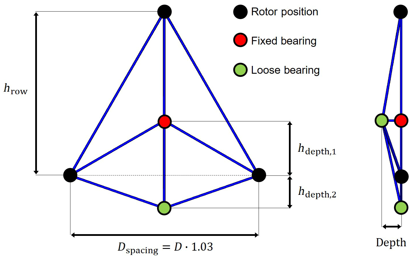
The simplified support structure design is described with the example of an SD-MRS with three rotors, as seen in Fig. 1. An MRS support structure is composed of a tower and a space frame, connecting the RNAs to each other and with the tower. The space frame consists of tubular steel connections.
In the INNWIND project (Jamieson et al., 2017) the spacing between rotors Dspacing was set to the rotor diameter plus 5 %: . The project's simulations resulted in an increase in both thrust and power generation in comparison to a single rotor. A change to resulted in no change to the mean value for thrust and power production. Here in this study a is set.
All chosen layouts are based on equilateral triangles, so the vertical distance between rotor rows results in
The height of the first row results from a set blade tip ground clearance of 22 m.
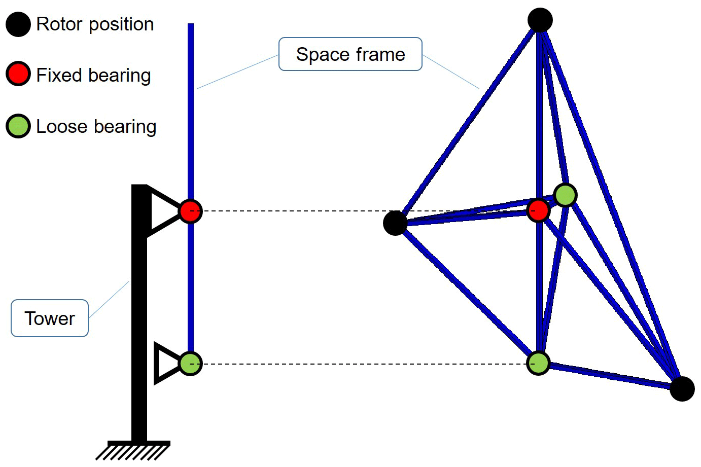
The tower and space frame are connected through yaw bearings, in this study always with a fixed–loose bearing combination. The MRS should be able to follow the wind via a global yaw system, meaning that the whole space frame should be able to align itself perpendicularly to the actual wind direction, rather than each rotor aligning itself. How the yaw bearings would be connected to the tower in detail is of no importance for this preliminary concept design study. The gravitational forces caused by the space frame and RNAs are transferred through the fixed bearing to the tower. Thrust forces vertical to the rotor planes are transferred through both fixed and loose bearings.
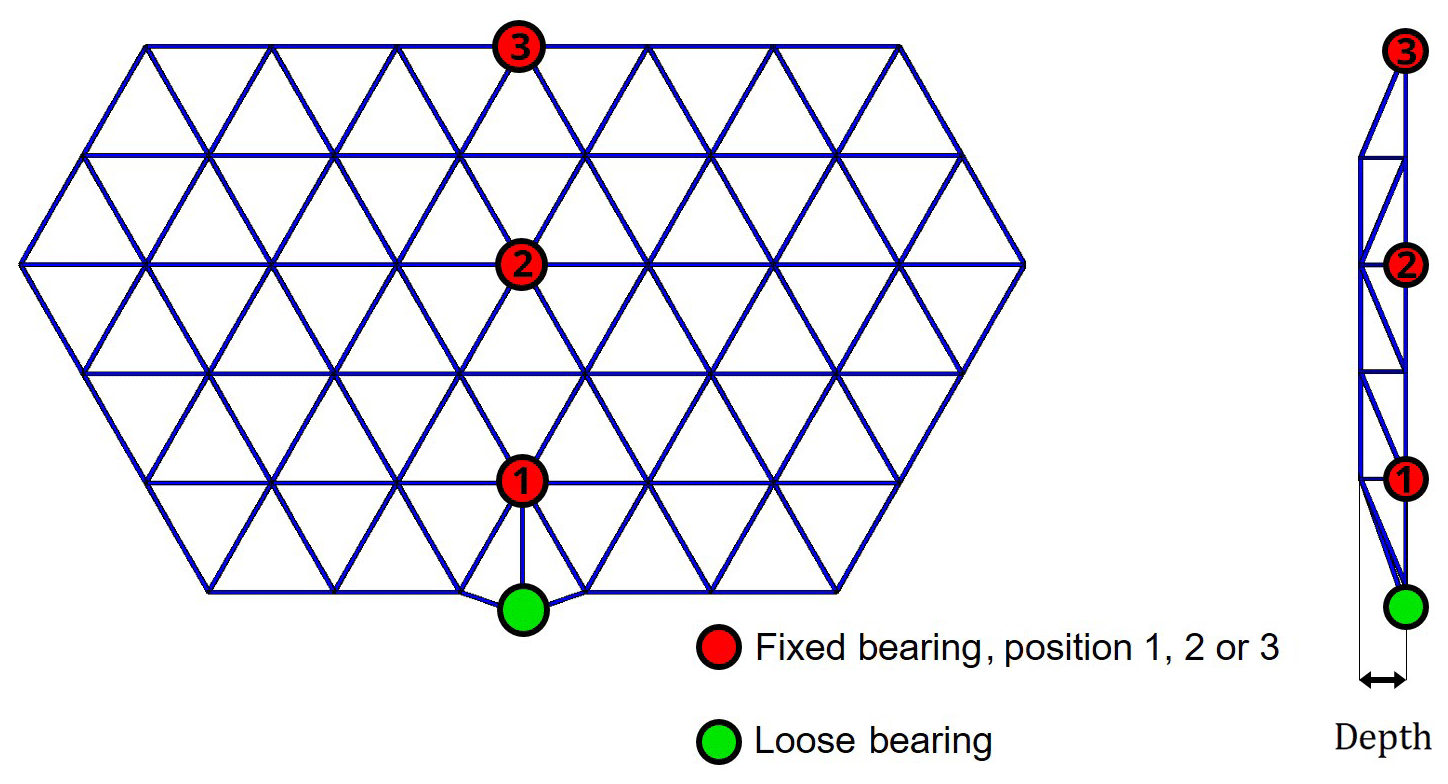
The vertical positions of the fixed and loose bearings, characterized with hdepth, 1 and hdepth, 2 are varied to investigate the influence on the cost and to find the optimal design regarding the cost. The fixed bearing is always on the tower top in this study, so the position also dictates the tower height; see Fig. 2. In the designs with three rotor rows, the parameter hdepth, 3 is needed. Another geometric design parameter that is varied is the depth of the space frame.
To dimension both the tower and the space frame, a simplified design load case is defined: maximum thrust force (at the steady rated wind speed) on all rotors simultaneously. Because of wind shear, turbulent wind, gusts and the pitching behavior, this is an artificial and somehow unlikely case, but for this study it represents a worst-case scenario regarding the ultimate loads.
The MRSs are designed in such a way that the space frame is modeled as an ideal truss work. To determine the member forces of the space frame, a finite element analysis (FEA) carried out via ANSYS APDL is used. The space frame members are modeled with bar elements. Bar elements have one local degree of freedom (DoF) per element node, the axial displacement, resulting in three global DoFs per node. The corresponding reaction force to the local axial displacement is the local axial force. The FEA requires initial diameters and wall thicknesses of the space frame members to determine and use the stiffness matrix. Since the space frame is modeled as an ideal truss work, the FEA solution of interest, the axial member force, is independent of the initial cross-section parameters.
The use of bar elements implies that there are no other DoFs and reaction forces in the nodes, apart from the axial ones. In reality the connections between the space frame elements and the rotors would be welded or bolted. Therefore, shear forces as well as bending and torsional moments would occur in the nodes. This could be modeled in the FEA via beam elements with six DOFs and reaction forces per node. With the use of beam elements, the FEA solution would depend on the initial cross section and the dimensioning process would be an iterative one for each space frame member. The differences between bar and beam element solutions were investigated and deemed neglectable for this preliminary study.
The thrust forces Ft on the rotors are calculated via the cT=0.827 value of the DTU turbine at the rated wind speed vrated=11.4 m s−1 (Bak et al., 2013), the scaled rotor diameter Drotor and ρair=1.225 kg m−3 (IEC 61400-1, 2019):
This is still under the assumption of an unchanged tip speed ratio λ due to scaling as well as of unchanged cP-λ and cT-λ curves.
Also acting on the support structure are the gravitational forces of the RNAs with an applied partial safety factor of γf, gravity=1.35. The partial safety factor for the thrust forces is set to γf, thrust=1.5 instead of to the suggested value of 1.35 according to IEC 61400-1 (2019). This is due to the simplicity of the design and to compensate for the simplified load case. Both kinds of forces are modeled as external forces acting on the rotor nodes of the space frame in the FEA.
The yaw bearings are modeled as boundary conditions with their respective DoFs on the respective space frame nodes. The fixed bearing disables all three spatial translations; the lower loose bearing has one DoF in the tower height direction. In Fig. 2 a loose bearing is seen at the back behind the fixed bearing. This is required for the FEA simulation to run, otherwise the model would not be kinematically determined. The space frame could still rotate, and this would result in a singular reduced stiffness matrix.
The dead load of the space frame and the drag forces of both the space frame and the tower are neglected. This is due to the fact that both the tower and the space frame are going to be dimensioned and an iterative process is to be avoided.
The space frame members are first dimensioned against ultimate strength with an applied safety factor for material of γm=1.1 and an assumption of a thin-walled tube; the wall thickness t is much smaller than the diameter, D: t≪D.
A ratio for the wall thickness to diameter is defined as . This is set to for the space frame bars and for the tower. For the cross section it follows that
For both the space frame and the tower a construction steel with a yield strength of σyield=355 MPa is used. Based on and the FEA-based axial forces Fbar, i, including both safety factors for loads, the bar diameters Di can be calculated now:
If necessary, in case of a compression state in the member element, a redimensioning against stability (Euler's critical load) with an applied safety factor for buckling of γm, buckling=1.2 is required. Since both ends of the members are free to rotate in theory, the column effective length factor lk is set to lk=li, the whole length of each space frame bar element i. Euler's critical load is defined as
with Young's modulus E=2.1e5 MPa and area moment of inertia for bending Ib. Again, like with the cross section A, a simplification for thin-walled tubes can be used (Wriggers et al., 2007):
In the case of a positive member axial force, the member is in a tension state and stability is of no concern. A negative axial force means a compression state. If the difference Ncrit−Fbar is negative, the bar diameter can be dimensioned with
The conclusive bar diameter is set to the maximum of Di and Di, buckling.
The tower diameters and wall thicknesses are determined by the tower bending reaction moment. The bearing reaction forces from the FEA solution are checked against the analytical solution. There, the space frame is assumed as a rigid beam supported through a fixed and a loose bearing, loaded with the thrust forces of the rotors. The reaction forces of the bearings are the external forces on the tower. These reaction forces induce a tower bending reaction moment Mb in the tower. Based on the bending stress , with the moment of resistance Wb, the tower can be dimensioned. Again, a simplification for thin-walled tubes can be used:
The tower diameter Dtower follows as
Since there is no bending moment at the tower top based on this simplified approach, the tower diameter would result in zero. The space frame is connected with the tower via a fixed bearing, and therefore the gravitational force resulting from the RNAs and the already-dimensioned space frame acts as an axial force at the tower top. Similarly to Eq. (8) the tower top diameter is calculated.
After dimensioning the space frame and tower, the volume of each part can be calculated and therefore the masses with the density ρsteel=7850 kg m−3. Masses for the RNAs, space frame and tower are now known and need to be multiplied with cost-per-mass factors. These factors are obtained from a turbine cost splitting (Jamieson, 2018), a CAPEX assumption (Fraunhofer ISE, 2018) and selected free available turbine data. The resulting factors can be seen in Table 1. The calculated cost factor values for the tower, rotor and nacelle are in good accordance with Jamieson et al. (2017). The assumption for the space frame cost factor is taken from their study.
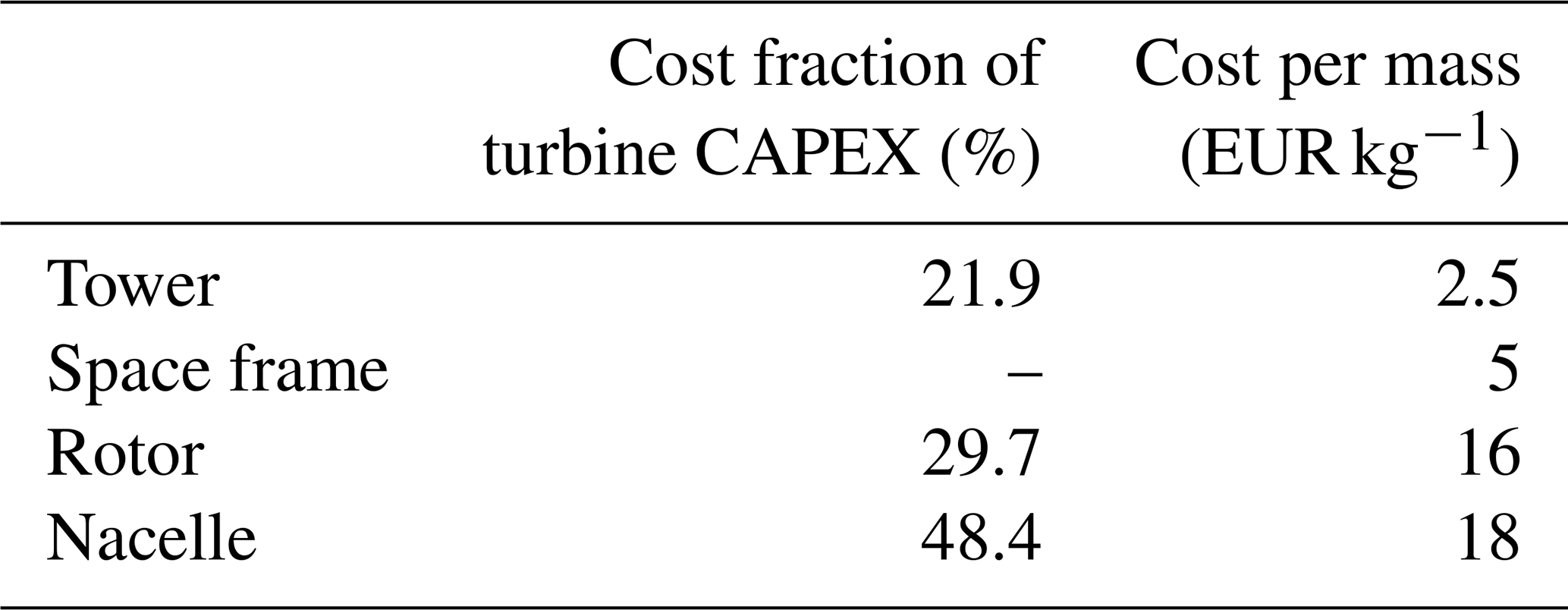
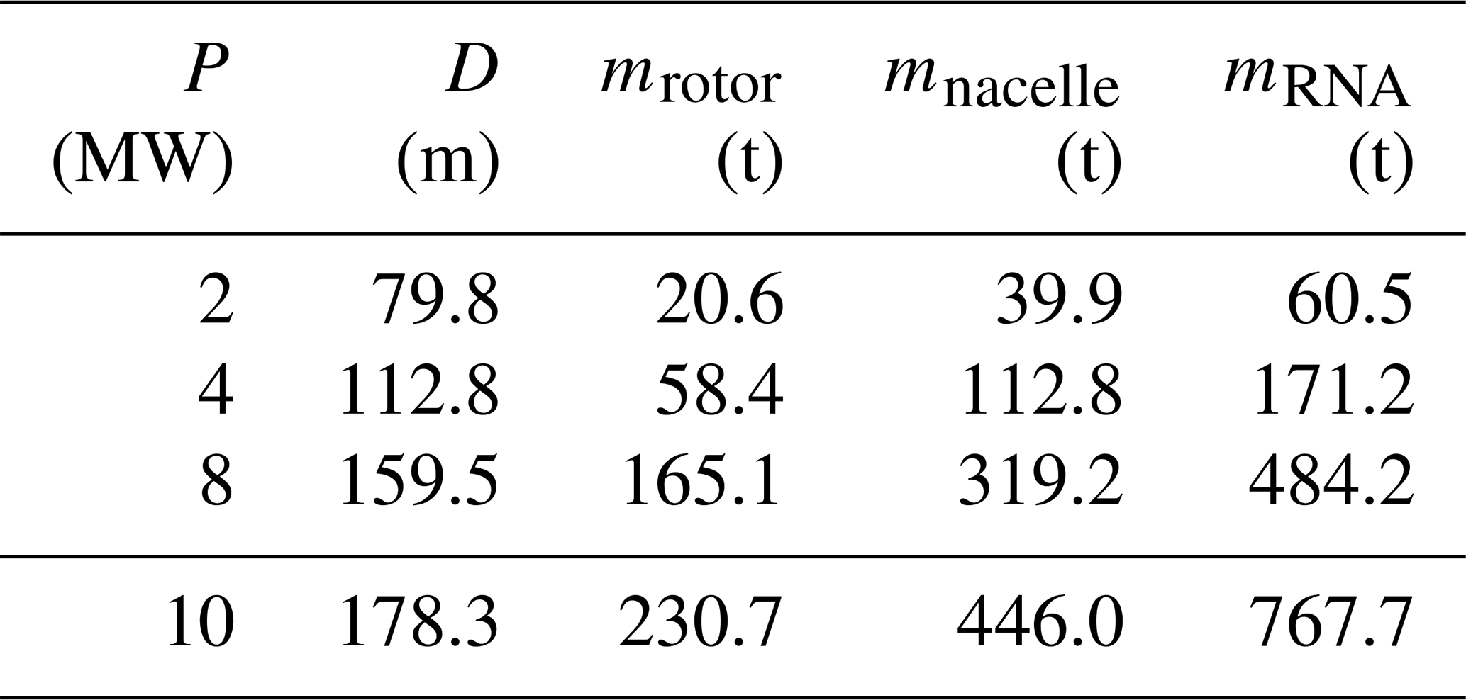
Table 2Scaled rotor values for the SD-MRSs and initial DTU rotor values.

Each SD-MRS design is simulated for each design parameter combination of hdepth, i and the depth of the space frame.
The energy yield of the MRS is determined based on an assumed Rayleigh wind speed distribution with a mean wind speed vmean=10 m s−1 (wind turbine class I; IEC 61400-1, 2019) and reference height href=167.9 m (hub height of the INNWIND 20 MW single rotor; Pontow et al., 2017).
With the cost and the annual energy production (AEP) of the designs, the SCoE can be calculated:
with an assumed wind turbine lifetime of nl=25 years.
To compare and normalize the SCoE values, a power-equivalent SR is designed with the same assumptions as the SD-MRS (blade tip clearance, loads, etc.).
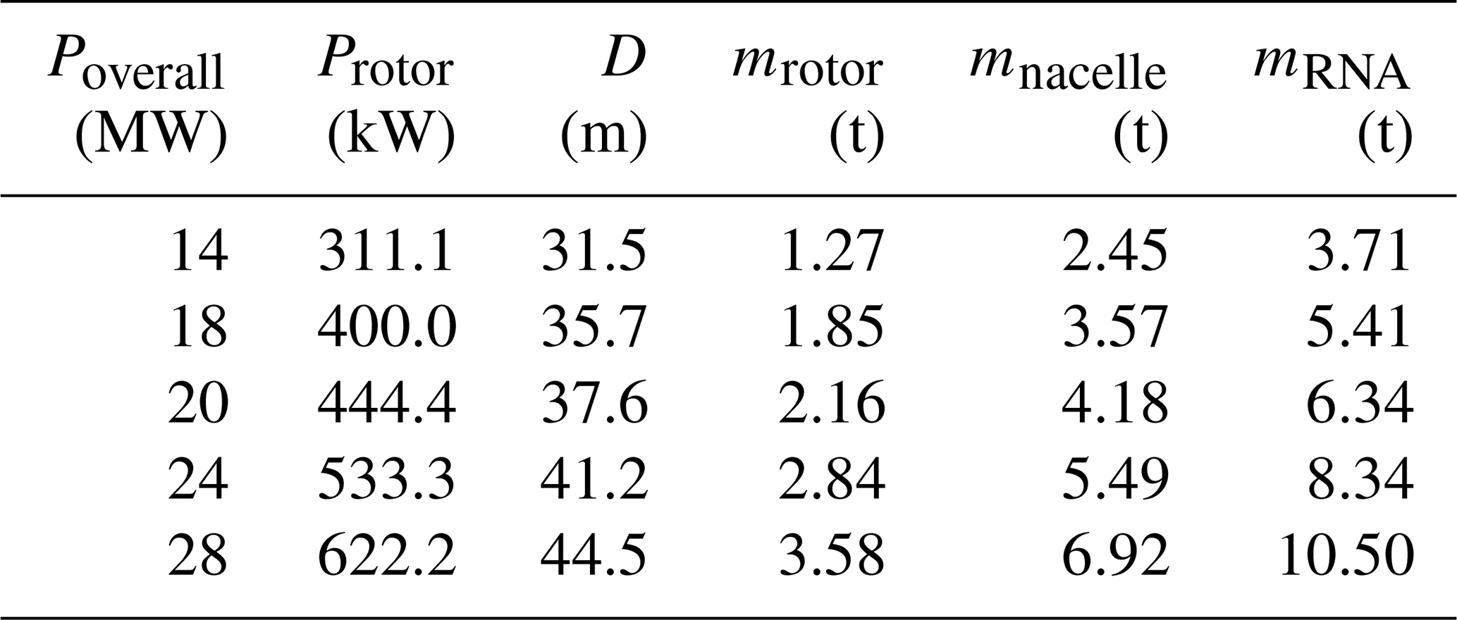
To keep the design space somehow limited and to reflect currently available turbines on the market, the rotors for the SD-MRS are set to a single capacity of 2, 4 or 8 MW. Table 2 shows the downscaled DTU 10 MW rotor values for the 2, 4 and 8 MW SD-MRS rotors. All layouts of the SD-MRS and the MD-MRS are designed with one set rotor capacity per design, meaning that there is no mixture of rotor sizes in one MRS design.
Possible rotor numbers are set to three (tri-rotor), five (penta-rotor), seven (hepta-rotor) or nine (ennea-rotor) rotors. An even-numbered SD-MRS would result in a cantilever design with or without steel ropes to reduce loads. These cantilever designs and therefore even-numbered SD-MRSs are not considered in this study. The odd-numbered SD-MRS layouts are all designed with equilateral triangles, which results in the highest packing density of the rotor area.
Three possible rotors and four possible numbers of rotors would result in 12 possible overall capacity combinations, ranging from to . The goal is to be in the 20 MW range, so five overall capacity combinations ranging from 14 to 28 MW are set.
-
Tri-rotor (3⋅8 MW resulting in 24 MW). The three rotors can be arranged in two ways: one rotor in the lower row and two in the upper row (increasing order, SD-MRS design no. 1) or in the upside-down way (decreasing order, SD-MRS design no. 2). Design no. 1 has the advantage of a higher energy yield, based on wind shear, compared to design no. 2. The disadvantage of design no. 1 is the higher tower base moment, resulting in higher cost.
-
Penta-rotor (5⋅4 MW resulting in 20 MW). The five rotors can also be arranged in an increasing or decreasing order. Two versions are designed for increasing and decreasing order, each with the same rotor layout but a slightly different arrangement of the bars.
-
Hepta-rotor (7⋅2 MW resulting in 14 MW or 7⋅4 MW resulting in 28 MW). Additionally to the increasing or decreasing order, a circular or hexagonal arrangement is possible.
-
Ennea-rotor (9⋅2 MW resulting in 18 MW). Two or three rows of rotors are possible, both with increasing and decreasing order.
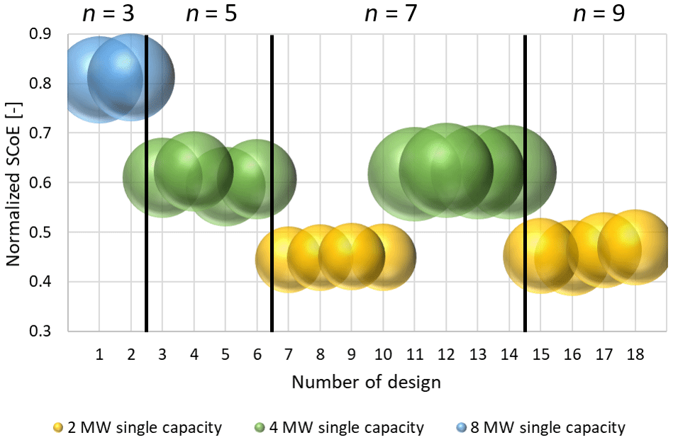
This results in an overall number of 18 designs for the SD-MRS, as seen in Fig. 3.
The design parameters shown earlier, hdepth and depth, are varied via unitless ratios, and the costs are calculated. Since the variation of these design parameters does not change the heights of the rotors, there is no influence of the variation on the energy yield of each design. To find the minimum SCoE for each design, the minimum costs (CAPEX) are determined. These minima are determined manually with no incorporation into an overarching mathematical optimization approach of the dimensioning procedure.
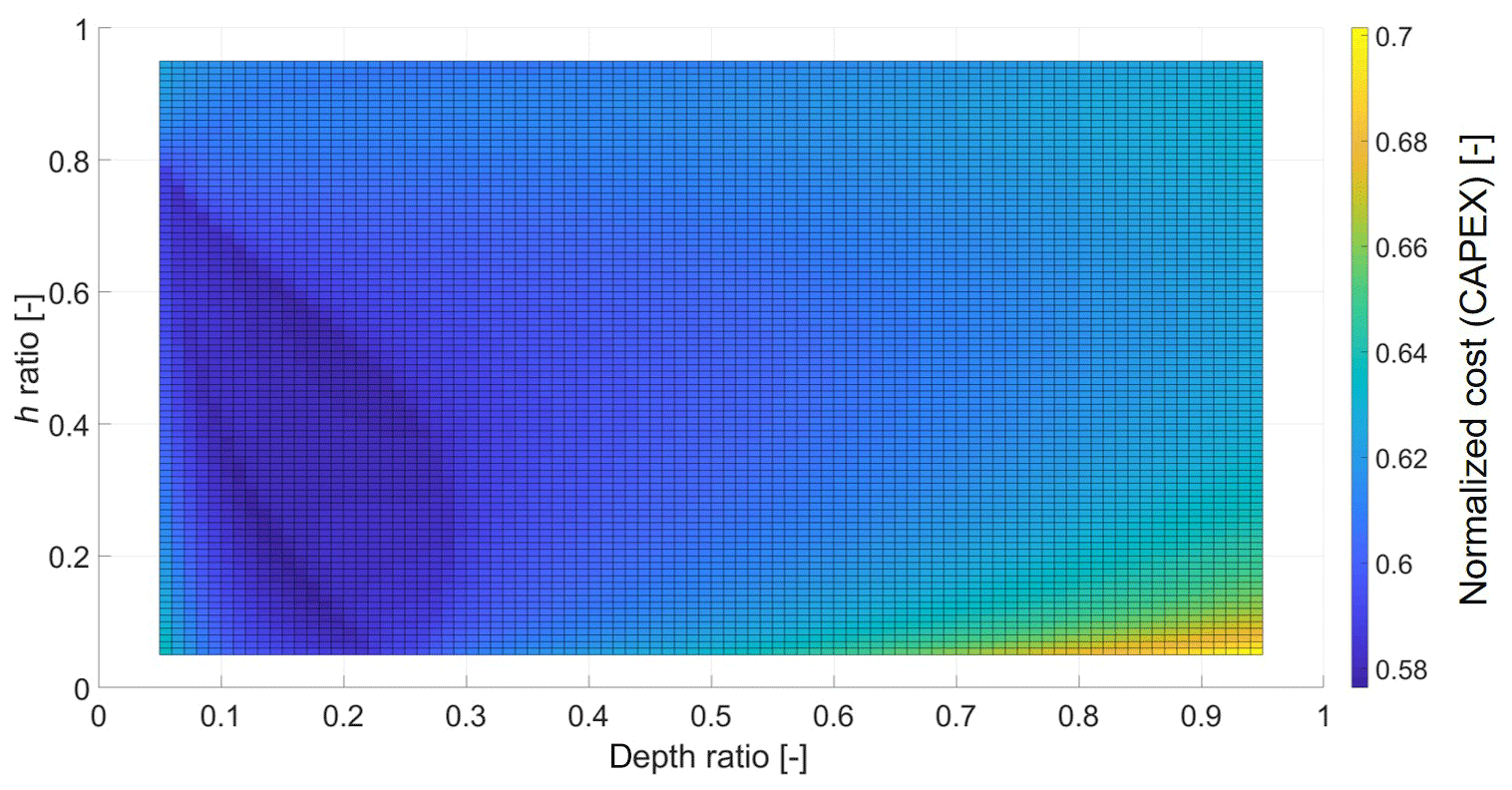
Almost all designs have three design parameters, since they have two hdepth parameters. In the case of the tri-rotor with an increasing number of rotors, design no. 1, there are only two design parameters and the cost based on the variations can be visualized as a response surface, as seen in Fig. 4. There, the costs are normalized to the value of the 20 MW SR.
The edges in the response surface are due to changes in the load distribution and the compression–tension behavior of the members, resulting in steep changes in the masses and therefore the cost.
In Fig. 5 the results of the optimized values for the simplified SCoE of the 18 SD-MRS designs are shown. The values are normalized to the value of a 20 MW SR. The bubble diameter indicates the overall SD-MRS capacity. With the exception of the ennea-rotors with three rows (design nos. 15 and 16), all designs with an increasing order of rotors are slightly more favorable than those with a decreasing order. There, the increase in energy yield outweighs the higher tower base moment. The differences between design nos. 3 and 4 on the one hand and design nos. 5 and 6 on the other are due to a better load distribution, resulting from a different bar layout.
The three levels of SCoE values correlate with the rotors used in the designs. The designs with the lowest SCoE are the ones with the 2 MW rotors; on the intermediate SCoE level are the 4 MW rotors and on the highest SCoE level the 8 MW rotors.
The lower costs are due to the small fraction of tower and space frame mass relative to the overall mass. Design drivers for the SD-MRS are the RNA masses; they benefit from smaller rotors based on cubic scaling.
As a first venture into MD-MRS designs, the INNWIND design with 45 rotors is used in a slightly modified version. The number of rows and rotors per row are unchanged, and the layout can be seen in Fig. 6.
The overall capacity for the MD-MRS is set to the same values as the SD-MRS to obtain a direct comparison. This results in the values shown in Table 3.
The design parameters to be varied are again the depth of the structure and the fixed bearing position and therefore the tower height. Instead of a quasi-continuous variation of the fixed bearing position over the height, three discrete positions are investigated: position 1 in the second row at the bottom, position 2 in the middle of the space frame and position 3 at the top. All three variants have the loose bearing in the first space frame row.
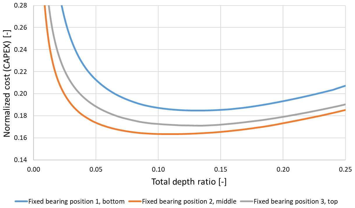
Figure 7 shows the normalized cost (CAPEX) of the 14 MW MD-MRS for the three fixed bearing positions plotted over the unitless total depth ratio. The costs are normalized to the cost value from the 20 MW SR. The total depth ratio indicates the ratio of depth to the width of the space frame. All three curves have a minimum of cost between 0.1 and 0.13 of the total depth ratio, meaning that the optimal design has a depth of 10 %–13 % of the space frame width. There, the loads of the space frame members have an optimal distribution, resulting in the lowest cost. Comparing the three fixed bearing positions, position 1 at the bottom has universally the highest cost. At this position the space frame rests with almost the whole weight on the tower and on itself. Almost all members are in a compression state and need to be redimensioned due to stability after the initial strength dimensioning, resulting in high space frame cost. The upside of this fixed bearing position 1 is a relatively short tower compared to the other positions and therefore lower tower cost. For fixed bearing position 3 the behavior is quite the opposite. The highest of the three tower versions is present, resulting in the highest tower cost. The space frame hangs on the tower, resulting in tension state members without the need to redimension against buckling. This results in low space frame cost. Fixed bearing position 2 shows the overall lowest cost of the three fixed bearing positions. The MD-MRS designs with 18 MW to 28 MW show the same results: optimal total depth ratio of around 0.1 to 0.13 and an optimal fixed bearing position 2 in the middle of the space frame.
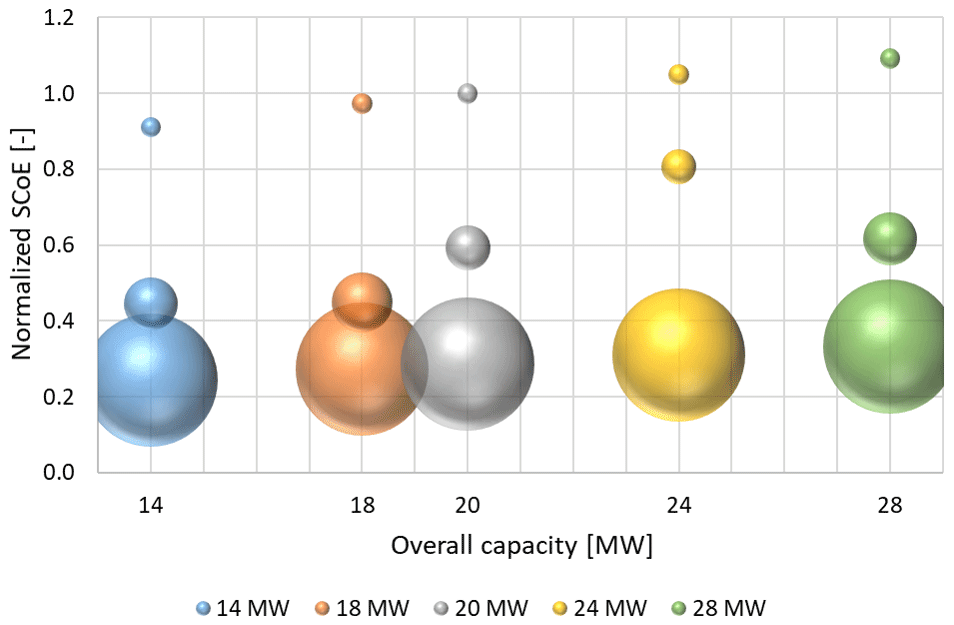
In Fig. 8 the SCoE results of SD-MRS, MD-MRS and SR are presented, normalized to the 20 MW SR value. The size of a bubble indicates the number of rotors; the smallest ones indicate the SR; the intermediate-sized bubbles indicate the SD-MRS; and the big bubbles denote the MD-MRS with a fixed number of 45 rotors. The SD-MRS is represented by the one design with the lowest SCoE from each overall capacity level. The SR and the MD-MRS values progress linearly over the overall capacity, based on cubic scaling. The conclusion here should not be to build up an MRS with a high number of rotors and a small overall capacity. It just seems that way since only a fixed number of rotors was investigated for the MD-MRS. The investigation with a variable, high number of rotors is missing and seems to be the next step. The tri-rotor shows the least potential to reduce cost, based on the relatively large rotors and therefore cost.
The aim of this study was to develop a simplified method for preliminary calculations of masses and therefore costs of multi-rotor wind turbine systems. The simplifications in the dimensioning process were used to avoid iterations for convergence and to allow for a fast way to investigate a variety of designs and design parameters.
Several SD-MRS designs were designed, simulated and optimized regarding the cost. The optimal design configurations were determined manually based on the simplified and fast dimensioning approach used.
The space frame of an MRS is sensible to the design parameters, since the load distribution can change with the design. Members can change from a tension to a compression state or the other way around. Stability seems to have a big influence since many space frame members needed to be redimensioned when in the compression state.
The SD-MRS designs with small single rotors showed the highest potential to reduce cost. One particular MD-MRS design with 45 rotors was also investigated and showed an optimal depth-to-width ratio for the space frame of 10 %–13 %. A fixed bearing position and therefore a tower height in the middle of the space frame was most promising. Overall the MD-MRS showed more potential than the SD-MRS to reduce cost.
Next steps include more MD-MRS designs with variable numbers of rotors. With increasing complexity in future works due to a growing number of designs and design parameters, a framing of the dimensioning process as part of a formal optimization approach needs to be considered.
After that, one or two promising designs will be analyzed in detail, regarding design load cases according to IEC 61400-1 (2019), fatigue analysis, local shell or plate buckling, and dynamic behavior (modal analysis).
All necessary research data have been included in the paper. For further information please contact the authors.
SvS performed all simulations and wrote the pre- and postprocessing code as well as this paper. PD and MT helped formulate the ideas and gave technical advice in the regular discussions. PD helped with the cost-to-mass factors. All authors reviewed this paper.
The authors declare that they have no conflict of interest.
This article is part of the special issue “Wind Energy Science Conference 2019”. It is a result of the Wind Energy Science Conference 2019, Cork, Ireland, 17–20 June 2019.
The content of this paper was developed within the project X-Rotor/X-Multirotor, part of X-Energy, which is in cooperation with Siemens Gamesa Renewable Energy (SGRE), who we would like to thank here.
This research has been supported by the German Federal Ministry of Education and Research – BMBF (grant no. 13FH1I04IA).
This paper was edited by Athanasios Kolios and reviewed by two anonymous referees.
Bak, C., Zahle, F., Bitsche, R., Kim, T., Yde, A., Henriksen, L. C., Natarajan, A., and Hansen, M.: Description of the DTU 10 MW reference wind turbine, DTU Wind Energy Report-I-0092, Technical University of Denmark, p. 5, 2013. a, b, c
Fraunhofer ISE: Stromgestehungskosten: Erneuerbare Energien, available at: https://www.ise.fraunhofer.de/content/dam/ise/de/documents/publications/studies/DE2018_ISE_Studie_Stromgestehungskosten_Erneuerbare_Energien.pdf (last access: 20 August 2020), 2018. a
IEC 61400-1: IEC 61400-1, edn. 4, Wind energy generation systems – Part 1: Design requirements, Guideline, International Electrotechnical Commission (IEC), 2019. a, b, c, d, e
Jamieson, P.: Innovation in Wind Turbine Design, John Wiley & Sons, New York, 2018. a, b, c, d
Jamieson, P., Branney, M., Hart, K., Chaviaropoulos, P., Sieros, G., Voutsinas, S., Chasapogiannis, P., and Prospathopoulos, J. M.: Innovative Turbine Concepts – Multi-Rotor System, INNWIND Deliverable 1.33, INNWIND, 2017. a, b, c, d, e
Pontow, S., Kaufer, D., Shirzahdeh, R., and Kühn, M.: Design Solution for a Support Structure Concept for future 20 MW, INNWIND Deliverable 4.36, INNWIND, 2017. a
van der Laan, M. P., Andersen, S. J., Ramos García, N., Angelou, N., Pirrung, G. R., Ott, S., Sjöholm, M., Sørensen, K. H., Vianna Neto, J. X., Kelly, M., Mikkelsen, T. K., and Larsen, G. C.: Power curve and wake analyses of the Vestas multi-rotor demonstrator, Wind Energ. Sci., 4, 251–271, https://doi.org/10.5194/wes-4-251-2019, 2019. a
Wriggers, P., Nackenhorst, U., Beuermann, S., Spiess, H., and Löhnert, S.: Technische Mechanik kompakt – Starrkörperstatik – Elastostatik – Kinetik, edn. 2, Springer-Verlag, Berlin, Heidelberg, New York, 2007. a