the Creative Commons Attribution 4.0 License.
the Creative Commons Attribution 4.0 License.
 | 04 Aug 2022
Vertical wake deflection for floating wind turbines by differential ballast control
Emmanouil M. Nanos
Simone Tamaro
Dimitris I. Manolas
Vasilis A. Riziotis
This paper presents a feasibility analysis of vertical wake steering for floating turbines by differential ballast control. This new concept is based on the idea of pitching the floater with respect to the water surface, thereby achieving a desired tilt of the turbine rotor disk. The pitch attitude is controlled by moving water ballast among the columns of the floater.
This study considers the application of differential ballast control to a conceptual 10 MW wind turbine installed on two platforms, differing in size, weight, and geometry. The analysis considers the following: (a) the aerodynamic effects caused by rotor tilt on the power capture of the wake-steering turbine and at various downstream distances in its wake; (b) the effects of tilting on fatigue and ultimate loads, limitedly to one of the two turbine-platform layouts; and (c) for both configurations, the necessary amount of water movement, the time to achieve a desired attitude, and the associated energy expenditure.
Results indicate that – in accordance with previous research – steering the wake towards the sea surface leads to larger power gains than steering it towards the sky. Limitedly to the structural analysis conducted on one of the turbine-platform configurations, it appears that these gains can be obtained with only minor effects on loads, assuming a cautious application of vertical steering only in benign ambient conditions. Additionally, it is found that rotor tilt can be achieved on the order of minutes for the lighter of the two configurations, with reasonable water ballast movements.
Although the analysis is preliminary and limited to the specific cases considered here, results seem to suggest that the concept is not unrealistic and should be further investigated as a possible means to achieve variable tilt control for vertical wake steering in floating turbines.
- Article
(4383 KB) - Full-text XML
- BibTeX
- EndNote


Power production from wind is typically organized in clusters of turbines, forming a wind plant. By interacting through their wakes within the plant, turbines are subjected to adverse effects that reduce their power capture and life expectancy, for both onshore and offshore installations. While in the latter case typical spacings between turbines are quite large, wake-induced losses can still be significant. In fact, in typical offshore conditions wakes persist many diameters downstream of the rotor because of the low turbulence of the atmospheric boundary layer (Vermeer et al., 2003).
Several remedies against these effects have been proposed so far, for example changing the induction factor (Steinbuch et al., 1988), redirecting (or “steering”) the wake path in the lateral or vertical directions (Parkin et al., 2001; Fleming et al., 2015; Campagnolo et al., 2016b; Fleming et al., 2019; Campagnolo et al., 2020; Doekemeijer et al., 2021), dynamically exciting the wake to enhance mixing (Frederik et al., 2020b, a), and various possible static and/or dynamic – largely unexplored – combinations thereof (Cossu, 2021b). Among these techniques, it appears that static induction is not very effective as far as power capture is concerned (van der Hoek et al., 2019). On the other hand, dynamic mixing techniques are promising, but further research is needed to address various concerns related to increased loading and actuator duty cycle (Wang et al., 2020), as well as to loss of effectiveness in turbulent inflows (Munters and Meyers, 2018). Among these various proposed solutions, static wake redirection is the most mature wind farm control technique available today, which has already been demonstrated in field experiments (Fleming et al., 2019, 2020; Doekemeijer et al., 2021) and is also offered as a market product (Energy, 2019).
Wake redirection is based on purposely misaligning the rotor with respect to the wind vector, thereby creating a force component normal to the wind direction that is responsible for deflecting the wake. Lateral wake deflection is based on yawing the turbine out of the wind. Since horizontal axis wind turbines are already equipped with active yaw control, this method does not require any radical hardware modification. This fact, together with the significant wake displacements that can be achieved without excessively increasing the loads on the steering turbine, is one of the reasons for the success of this technique. In fact, wake steering has been successfully implemented on wind turbines originally designed without taking this form of wind farm control into consideration (Fleming et al., 2019, 2020; Doekemeijer et al., 2021).
Vertical wake deflection works in the same way as lateral deflection: when the rotor is tilted about a horizontal axis, its thrust is inclined with respect to the ground; in turn, the equal and opposite reaction on the flow is also inclined, resulting in a vertical force component with respect to the ground that deflects the wake in the vertical direction.
There are, however, some key differences between the lateral and vertical deflection strategies.
First, contrary to lateral wake steering, standard wind turbine configurations do not offer an already-existing mechanism that can be employed for deflecting the wake vertically. The only exception is the case of downwind teetering rotors, where vertical wake deflection can in principle be achieved by tilting the tip-path plane through blade flapping; however, there are no large downwind teetering rotors on the market today.
Second, vertical steering presents a strong directional dependence. While also lateral steering is not exactly symmetric between left and right misalignments because of the spinning of the rotor (Fleming et al., 2018), deflecting the wake towards the sky or towards the ground has profoundly different effects. In fact, in vertically sheared flows, an upward vertical deflection moves the wake into a higher-speed flow region, whereas the opposite happens for a downward deflection. Furthermore, when subjected to a downward deflection the wake eventually interacts with the ground, resulting in a strong deformation of the wake structures and in its accelerated recovery (Scott et al., 2020).
Notwithstanding the technical difficulty of implementing vertical wake deflection, this concept has received some attention in the recent literature. For example, Srinivas et al. (2012) presented an analytical study of vertical steering and evaluated some engineering models in their ability to predict the vertical motion of the wake. Fleming et al. (2015) used computational fluid dynamics (CFD) to simulate a single column of two wind turbines with tilted rotors, while in the paper of Annoni et al. (2017) the authors simulated up to three turbines in a column; both studies reported significant power gains at the cluster level, caused by improved capture downstream that offsets more limited losses upstream. Simulation studies on more complex layouts were conducted by Cossu (2020, 2021a), where the front two rows of turbines in a farm were tilted, obtaining significant power gains at the wind plant level. The author also studied the effect that rotor size, longitudinal spacing between the turbines, and thrust setting can have on the plant power output. These studies have highlighted an interesting phenomenon, whereby downward wake deflection leads to the creation of high-speed streaks in the flow, which again are associated with significant power boosting at the plant level. Su and Bliss (2019) used a free-wake method to study a tilted rotor, reporting power benefits for a two-turbine column when deflecting the wake of the upstream machine towards the sky. Scott et al. (2020) performed wind tunnel measurements of a four-by-three grid layout using scaled wind turbine models, where the machines in the third row were tilted. Among other results, the authors reported a faster wake recovery for downward deflection than in the upward case.
In summary, the literature already reports a significant body of evidence indicating that vertical wake steering can be an effective form of wind farm control. Further potential gains could be possibly achieved by combining vertical and lateral steering, although this problem does not seem to have been explored yet. However, the problem of how vertical steering can be achieved in practice remains at present unsolved, except for the downwind teetering wind turbine configuration.
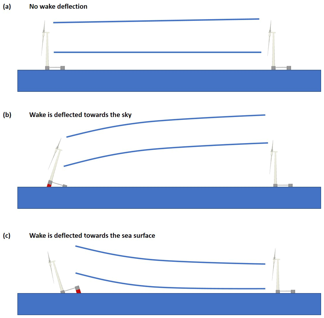
To address this gap, Nanos et al. (2020) proposed a novel way of implementing vertical wake steering for floating wind turbines. This new idea exploits the fact that semi-submersible platforms, which are among the most popular floating concepts (Liu et al., 2016), require the use of ballast to achieve a desired attitude with respect to the sea surface. Attitude control is commonly obtained by storing and distributing water among the columns of the platform in order to change the center of gravity position. Active ballast control systems are already installed on board semi-submersible platforms used by the oil industry; the same concept is included in some offshore-wind conceptual designs (Roddier et al., 1997), where its purpose is mainly to counteract the pitching moment created by the thrust force of the rotor. With reference to wind farm control, the idea pursued here is to use an active ballast control system to pitch the platform, this way achieving a desired tilting of the rotor disk and, therefore, a vertical deflection of the wake. The concept of vertical wake deflection through platform pitching by active ballast control is illustrated in Fig. 1.
The scope of the present work is to refine the concept first presented in Nanos et al. (2020). The objective here is clearly not to design an actual system implementing vertical wake steering by active ballast control but to perform a feasibility analysis, with the goal of answering the following basic questions:
-
Is it conceptually feasible to use differential ballast control to perform vertical wake steering for wind farm control? And what would be the most and least favorable configurations and operational conditions?
-
Can an existing ballast control system be used for this additional purpose (similarly to what has been done with yaw control for lateral wake deflection), or should the system be modified somehow?
-
Would such a system be able to reach sufficiently large pitch motions (and, hence, rotor tilt angles)? And what would be the achievable tilt rate and associated energy cost?
-
Could an existing floating wind system be used for vertical wake steering by ballast control, or would the turbine, platform, and/or mooring system need to be partially resized?
More specifically, this paper will do the following:
-
It will assess the effect of rotor tilt on the wake of a turbine and on the power yield of a column of two turbines. To this purpose, CFD simulations of a scaled wind turbine, validated with wind tunnel experiments, are employed. Expanding on previous tilt misalignment studies, which analyzed streamwise spacings of 6–8 rotor diameters (Fleming et al., 2015; Annoni et al., 2017; Cossu, 2021a; Scott et al., 2020), the present work considers distances of up to 12 rotor diameters, which is a more realistic spacing for offshore-wind applications.
-
It will make preliminary calculations of the quantity of water ballast that needs to be redistributed for achieving the necessary tilting of the rotor, along with estimating the associated energy expenditure.
-
It will assess the impact of the proposed method on the structural loading of the turbine, the platform, and its mooring system. Although semi-submersible platforms and turbines are designed and certified to withstand significant pitch excursions under extreme weather conditions, a specific assessment of the effects on the structure of this new form of wind farm control is important in order to evaluate the overall feasibility of the concept. To this end, hydro-aero-servo-elastic simulations of a conceptual wind turbine on a floating platform are utilized.
The article is organized as follows. Section 2 gives a description of two reference platforms and one wind turbine that are used for assessing the feasibility of the proposed concept. Section 3 analyzes the effects of tilting the rotor on the turbine wake and on the power of a two-turbine cluster through CFD simulations, which were first validated against experimental data. Section 4 presents the effects of tilt on the extreme and fatigue loads computed by hydro-aero-servo-elastic simulations. Section 5 assesses the differential ballast control concept on the basis of a hydrostatic analysis and presents an initial rough sizing of the system for the two different platform configurations. Finally, Sect. 6 presents the main conclusions and outlines possible future steps.
The present analysis is based on one reference wind turbine and two reference floating platforms. Unlike other wake control strategies, ballast control for vertical wake deflection is substantially affected by the design characteristics of the turbine and of the platform.
Regarding the turbine configuration, upwind wind turbines are favored when wake deflection towards the sky is considered because of the built-in uptilt used to increase rotor–tower clearance (Burton et al., 2001). In fact, the rotor plane is already tilted nose-cone up (typically by about 5∘); therefore, in order to achieve a given misalignment, a smaller additional rotation is needed for a nose-up attitude (upward wake deflection, as in Fig. 1b) than for a nose-down one (downward wake deflection, as in Fig. 1c). Consequently, smaller platform rotations are necessary for deflecting the wake towards the sky than those necessary for deflecting the wake towards the sea surface. Exactly the opposite happens for a downwind turbine, where the built-in uptilt used to increase rotor–tower clearance favors downward wake deflections, resulting in smaller platform angles when the wake is steered towards the sea surface than when it is steered towards the sky.
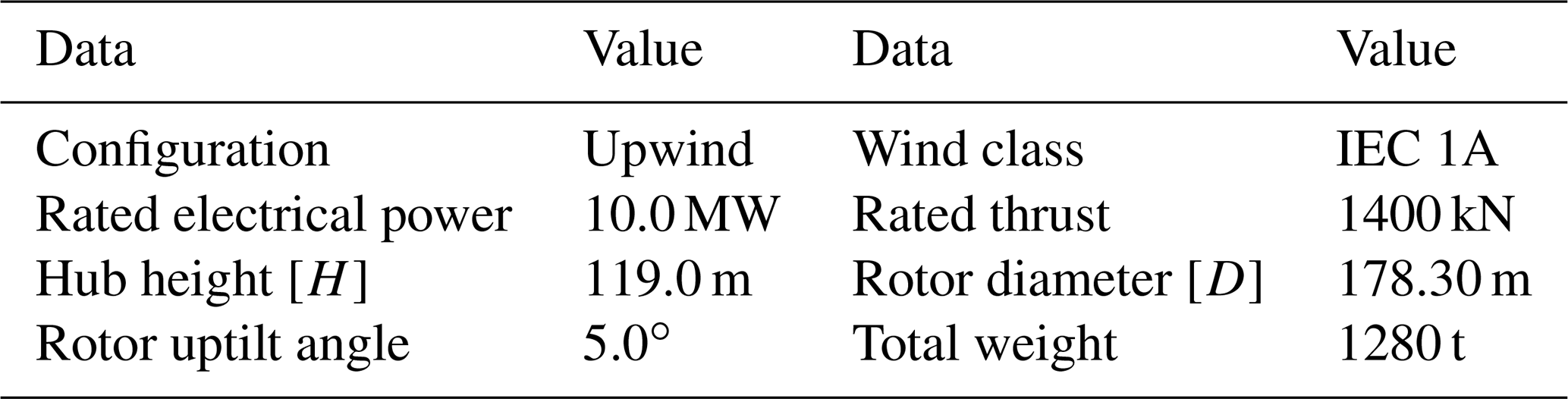
As shown by previous research (for example Cossu, 2020, 2021a; Scott et al., 2020) and later on in this paper, it appears that downward wake deflection is more effective in improving cluster power than upward deflection. From this point of view, a downwind turbine configuration appears to be better suited for this application than an upwind one. Notwithstanding this important difference between the two configurations, an upwind turbine is used in this work since it represents today's standard offshore configuration and no large downwind turbines are at present available on the market. The following analyses are based on the Danmarks Tekniske Universitet (DTU) 10 MW turbine (Bak et al., 2013), whose basic characteristics are reported in Table 1.
Table 1Basic characteristics of the DTU 10 MW reference wind turbine.
Since the present wake control concept is based on the pitching of the whole platform, the characteristics of the floater – in addition to those of the turbine – also play an important role. In fact, the ballast distribution that is required for a specific pitch attitude depends on the size, weight, and draft of the platform. Additionally, ballast is affected by where the turbine is located with respect to the platform, close either to its center or to its periphery. In the case the platform is not axially symmetric about the turbine tower, the yaw orientation of the turbine with respect to the platform also plays a role in determining the differential ballast that is necessary for a given attitude. Finally, it should be noted that, depending on the configuration of the system, a change in platform pitch can also imply – in addition to tilting – a vertical motion of the hub; as a result, the rotor can be exposed to a slightly different wind speed in a sheared inflow.
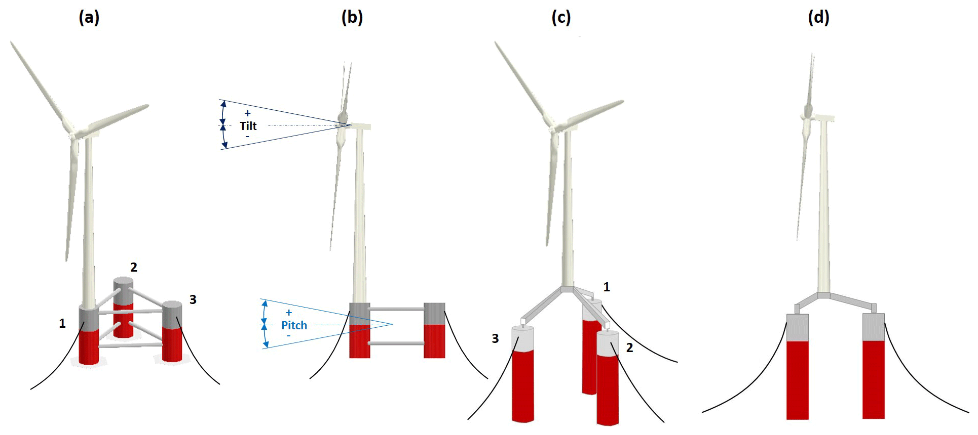
Figure 2Sketch of Platform A, based on the WindFloat concept (Roddier et al., 1997) (a, b). Sketch of Platform B, based on the INNWIND concept (Azcona et al., 2017; Manolas et al., 2018) (c, d).
In order to explore some of these configuration-related effects, the present paper makes use of two different reference platforms. The first one, hereafter called Platform A (Fig. 2a and b), is based on the concept developed in the WindFloat project (Roddier et al., 1997). The platform is composed of three columns made out of steel, arranged in a triangular configuration by connecting trusses, with the turbine directly placed on top of one of the columns. The second platform (Fig. 2c and d) is the tri-spar floater developed in the INNWIND project (Azcona et al., 2017; Manolas et al., 2018), hereafter called Platform B. This floater was developed to accommodate a 10 MW machine mounted on a steel structure at the center of three columns, and it represents a hybrid configuration between a semi-submersible and a large-draft spar buoy. This design uses concrete for the spars, resulting in a much heavier structure compared to Platform A. The principal characteristics of the two platforms are summarized in Table 2.
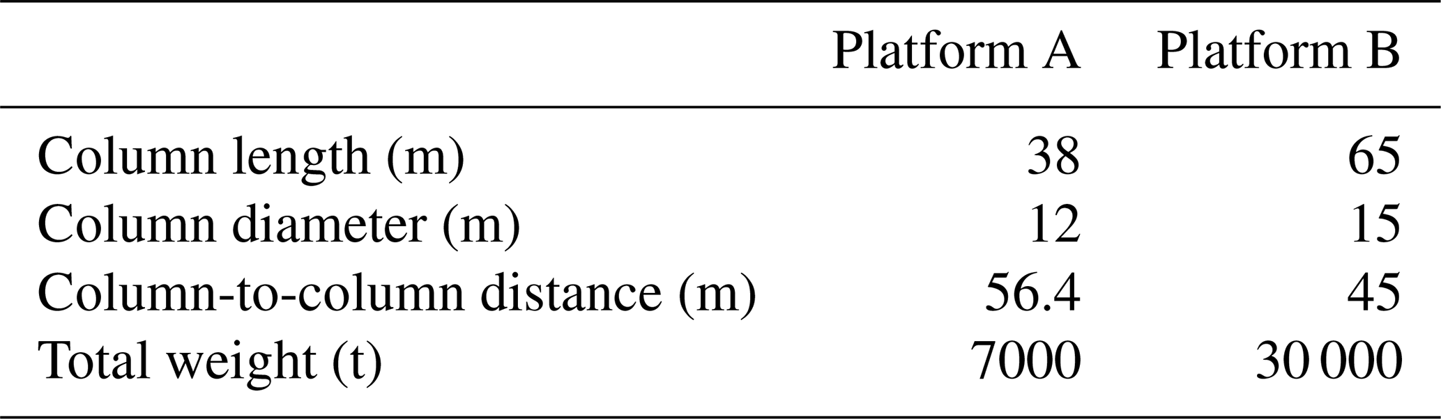
Figure 2b defines the angle conventions adopted in this paper. Tilt indicates the angle between the rotor axis and the wind vector, while pitch refers to the angle between the platform and the water surface. While the wind vector and water surface are assumed to always be parallel, the tilt and pitch angles are not necessarily equal to each other because of the built-in uptilt used in wind turbines to increase the clearance between rotor and tower with the purpose of relaxing the stiffness requirements on the blade. For a positive tilt, the rotor axis is above the horizon when looking upstream. Hence, an upwind wind turbine has a positive built-in uptilt, whereas a downwind machine has a negative one; additionally, positive tilt implies that the wake is deflected towards the sky, whereas for negative tilt the wake is steered towards the sea surface. Pitch follows the same sign convention. For better readability, instead of referring to positive and negative angles, the text will refer to wake-up and wake-down angles, respectively, which is a more intuitive terminology.
The effects of rotor tilt on wake development and downstream power capture were evaluated by a combined simulation–experimental study. The G06 scaled model (Nanos et al., 2022) of the reference 10 MW wind turbine was used for this purpose. Previous work by Wang et al. (2021) has shown that scaled wind turbines, designed according to the same specifications as those of the G06 model, are capable of producing highly realistic wakes in atmospheric boundary layer wind tunnels. A CFD simulation model of the turbine was first verified based on experimental measurements performed in the wind tunnel in a rotor-tilted condition and then used to explore the characteristics of the wake.
3.1 CFD validation and setup
CFD simulations were executed with a flow solver based on a large-eddy simulation (LES) actuator line method (ALM) implemented in foam-extend (Jasak, 2009), while the wind turbine lifting-line aerodynamics were modeled in FAST (Guntur et al., 2016). This framework has been validated in previous work (Wang et al., 2019), and it is further verified here in tilted conditions using new ad hoc wind tunnel measurements.
An experimental campaign was conducted in the BLAST atmospheric boundary layer wind tunnel at the University of Texas at Dallas (UTD). Further details on the wind tunnel and the G06 scaled model are available in Nanos et al. (2018, 2019, 2022). The model was operated at its optimum tip speed ratio and pitch angle. With the help of a tilting mechanism inserted between the nacelle and the tower top, the rotor was tested at three different attitudes: 0∘, 20∘ wake-up, and −20∘ wake-down.
The wake of the G06 was measured on a vertical plane at a 5 D downstream distance by stereo particle image velocimetry (S-PIV). The velocity at hub height was approximately equal to 10 m s−1; the turbulence intensity was 8.5 %, and the inflow had a vertical shear characterized by an exponent α = 0.2.
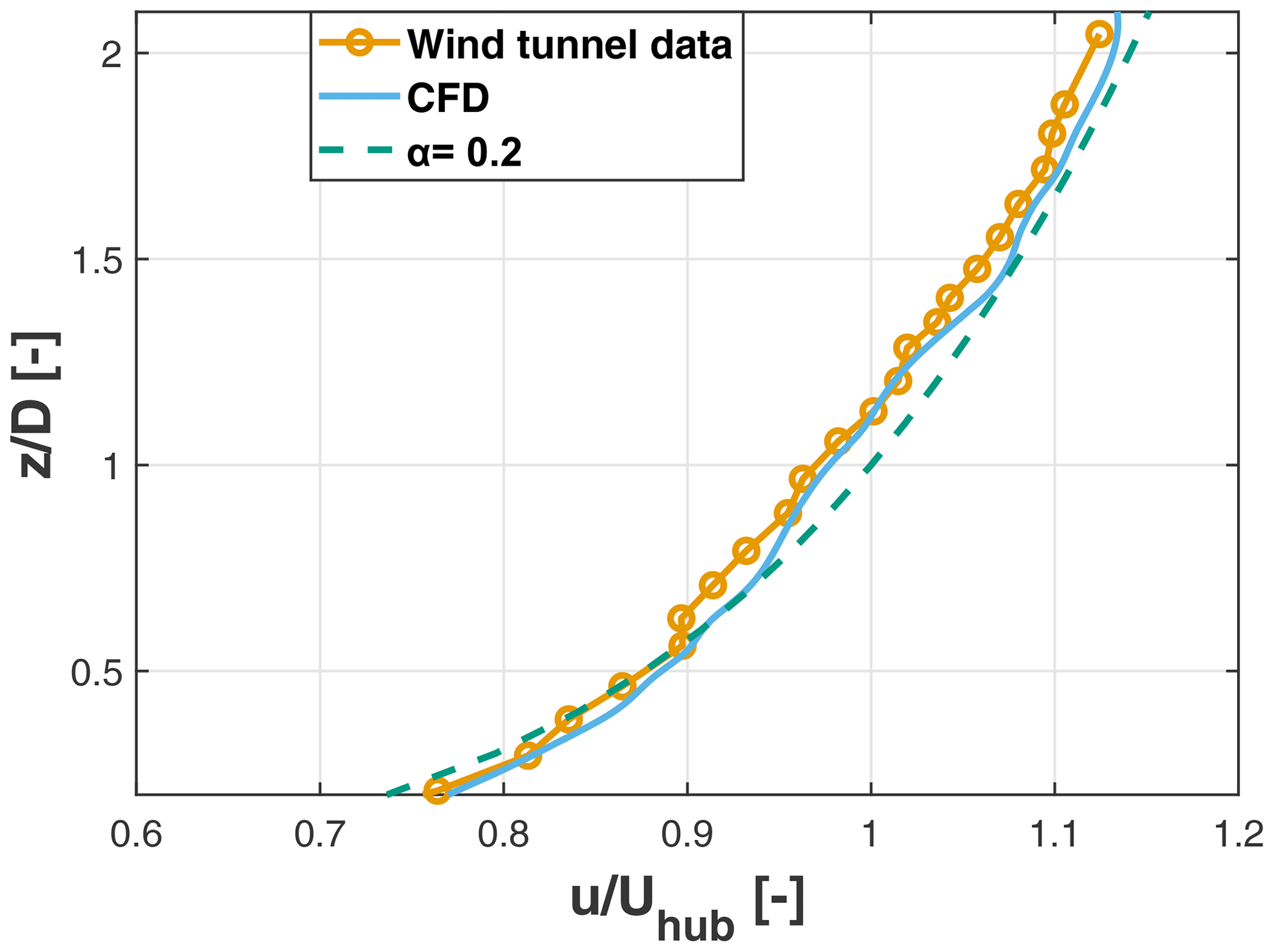
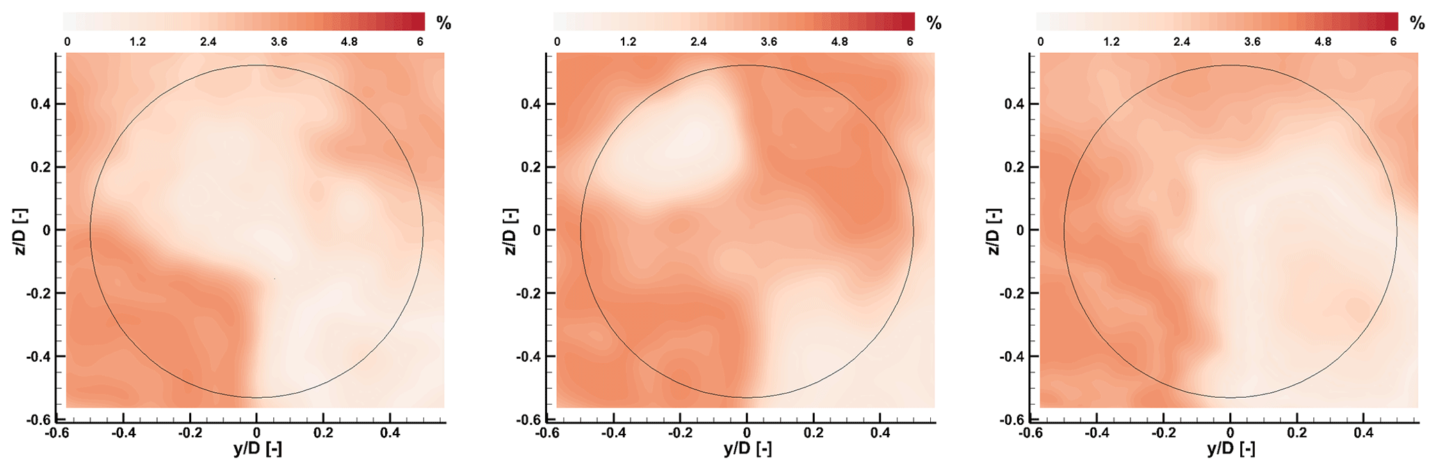
Figure 4Absolute percent error between S-PIV and CFD time-averaged streamwise flow speed 5 D downstream of the rotor, for three tilt angles. The black circle denotes the rotor circumference.
A first set of CFD simulations mimicked the experimental setup, including the tilting geometry; the wind tunnel walls; and the passive generation of the turbulent and sheared inflow, which was obtained by spires placed at the chamber inlet and roughness elements on the floor. Figure 3 shows the simulated and measured time-averaged vertical profiles of the inflow at the turbine location, which appear to be in very good agreement with each other. Figure 4 shows the absolute percent error between CFD and S-PIV measurements for the three tilt angles at an = 5 downstream distance. The error was calculated according to the following formula:
where u is the flow speed in the wake and Uhub the inflow speed at hub height, both quantities representing time-averaged streamwise values. Results show that the error is for most of the domain between 0 % and 2 %, reaching 4 % in some limited areas. This error is considered acceptable for the scope of the present analysis. Additional details on the experimental setup, the S-PIV data, and the comparison between experiments and simulations are available in Nanos et al. (2022).
3.2 Effects of tilt on the flow
After validating the CFD model for this specific setup, additional simulations were conducted at different rotor tilt angles. This second set of simulations was based on the configuration of Fig. 2a and b, where the rotor is facing away from the other two columns. This implies that, since the position of the turbine for each tilt angle is determined by the platform kinematics, a wake-up tilt rotation generates a small vertical lifting of the hub, whereas a wake-down tilt comes with a small downward motion.
To compute the power available in the wake, the power coefficient of the untilted configuration was obtained from the CFD results by computing a rotor-effective wind speed. Next, using the computed value of the power coefficient, the power in the wake was obtained from the longitudinal flow velocity component on the area of the rotor disk at various downstream positions, from 6 to 12 D.
Figure 5 shows contours of the normalized time-averaged streamwise velocity component. For brevity, the results are shown only at two downstream distances (namely, = 6 and = 12) and for three rotor tilt angles (0∘, 15∘ wake-up, and −15∘ wake-down). The deflection of the wake center is evident at = 6, but changes in the flow field are still noticeable even at = 12.
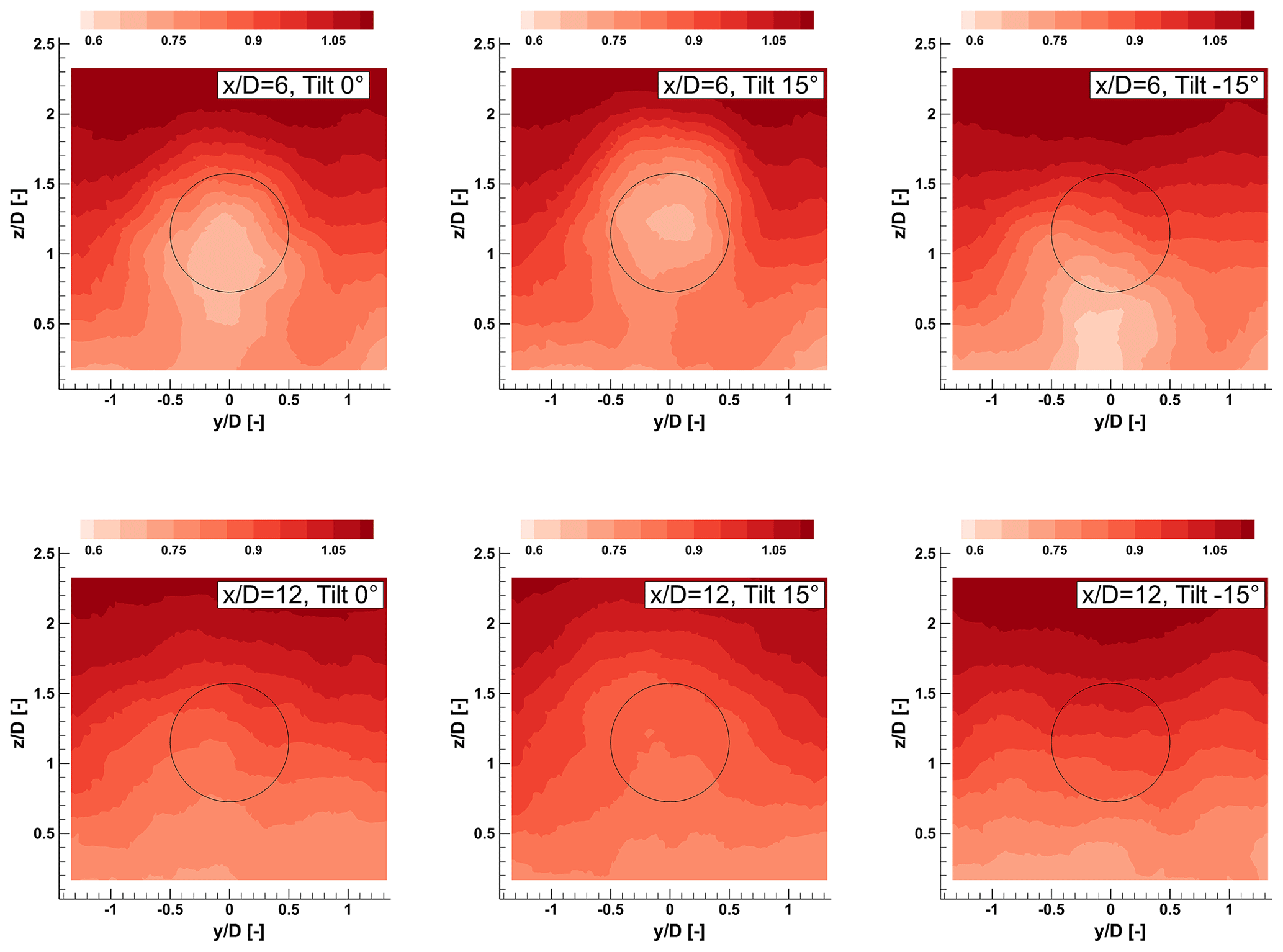
Figure 5Contours of normalized streamwise velocity on yz cross-planes (orthogonal to the flow) for two downstream distances and three rotor tilt angles. The black circle denotes the rotor disk circumference.
Because of the non-uniformity of the sheared inflow, the wake center is deflected towards the ground by 0.2 D even for the aligned rotor case. This effect can also be appreciated in Fig. 6, which shows normalized velocity contours on the xz midplane for the same tilt angles. The flow has a higher momentum above the wake than below it. As a result, turbulent mixing is stronger in the top part of the wake, resulting in a non-symmetrical vertical profile, as already observed in previous studies (Chamorro and Porté-Agel, 2009; Nanos et al., 2022). Therefore, as shown by the figures, the deflection of the wake towards the sea surface results in a higher-energy flow within the downstream rotor area.
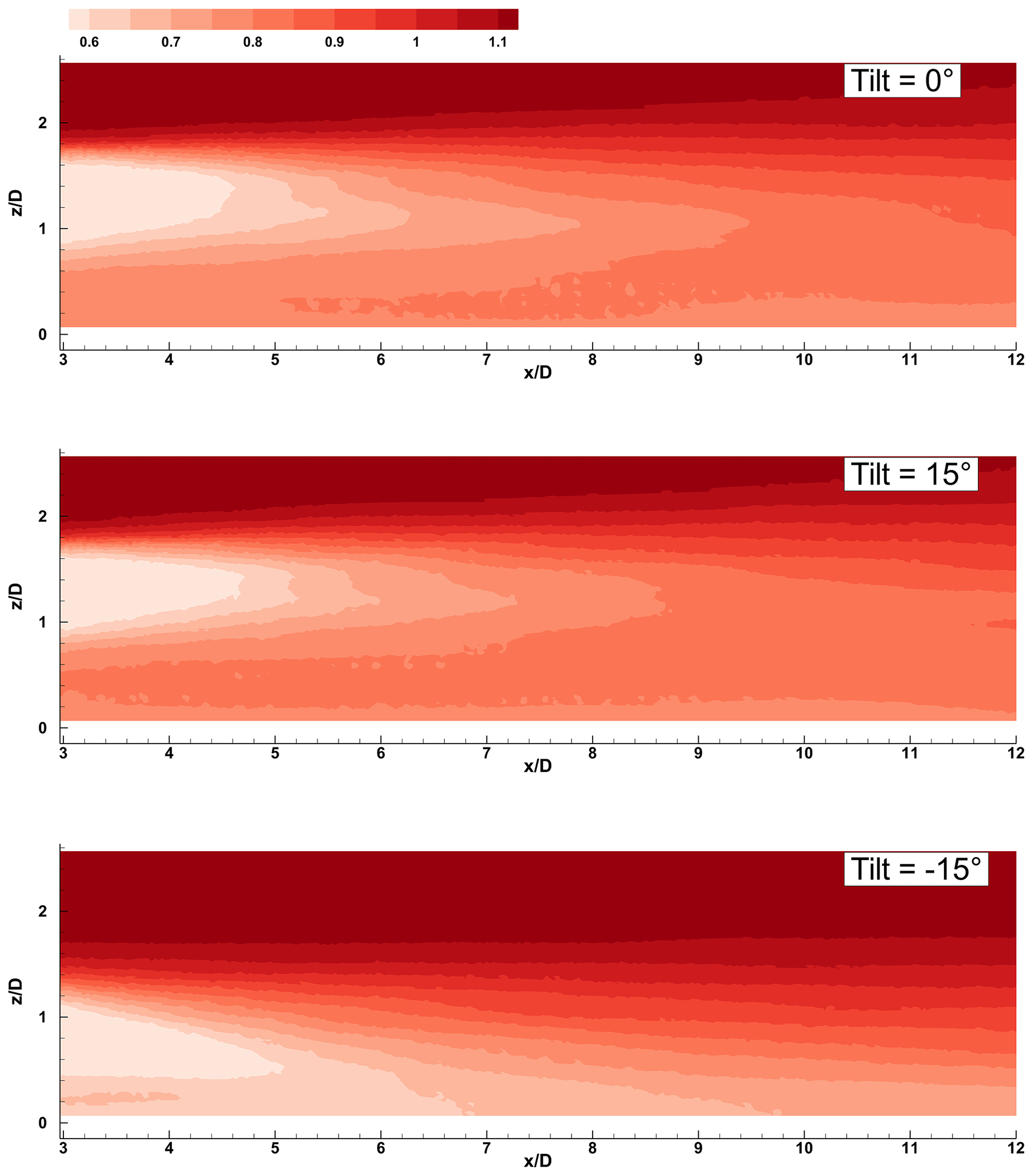
Figure 6Contours of normalized streamwise velocity on the xz longitudinal midplane for three rotor tilt angles.
Furthermore, it appears that the direction of wake deflection also has an effect on how fast the wake recovers. The recovery was calculated based on the integral of the speed 〈u〉 computed over a square area of size 2.5 D by 2.5 D, centered at hub height. This area is sufficiently large to enclose the wake for all simulated tilt misalignment cases. The value of the integral at = 2 was considered a reference, resulting in the following expression of the recovery ratio:
Figure 7 shows the wake recovery ratio for the tilt angles 0∘, 20∘ (wake-up), and −20∘ (wake-down). For the wake-down (negative) tilting the recovery rate, i.e., the slope of the linear best fit, is slightly higher than for the untilted case and almost double the one of the wake-up (positive) tilt case.
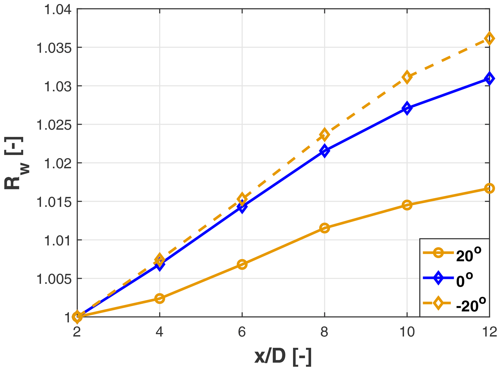
Figure 7Wake recovery ratio Rw for 0∘ (untilted), 20∘(wake-up), and −20∘(wake-down) rotor tilt angle.
3.3 Effects of tilt on power
Figure 8a reports the percent power drop for the wake-deflecting wind turbine as a function of the rotor tilt angle β. As expected, tilt misalignment reduces the power capture of the turbine, similarly to the classical yaw misalignment case (Campagnolo et al., 2016a). The results of the figure correspond to the configuration shown in Fig. 2a, where the rotor is facing away from the other two columns; in this and other cases, pitching the platform generates a vertical translation of the rotor that, in a sheared inflow, causes an extra variation in power capture. This effect is indeed visible in the figure, where positive pitch values are associated with slightly higher power capture than the same negative pitch values. Because of this lack of symmetry, the discrete points were best fitted with the modified cosine law , resulting in the values a = 0.99, b = 9 × 10⁻⁴, and p = 3.2. For the same rotor, the power drop yaw exponent was found to be p ≈ 2.01 (Nanos et al., 2022). However, since that result was obtained in laminar inflow conditions, a direct comparison between these two exponent values is probably not completely appropriate.
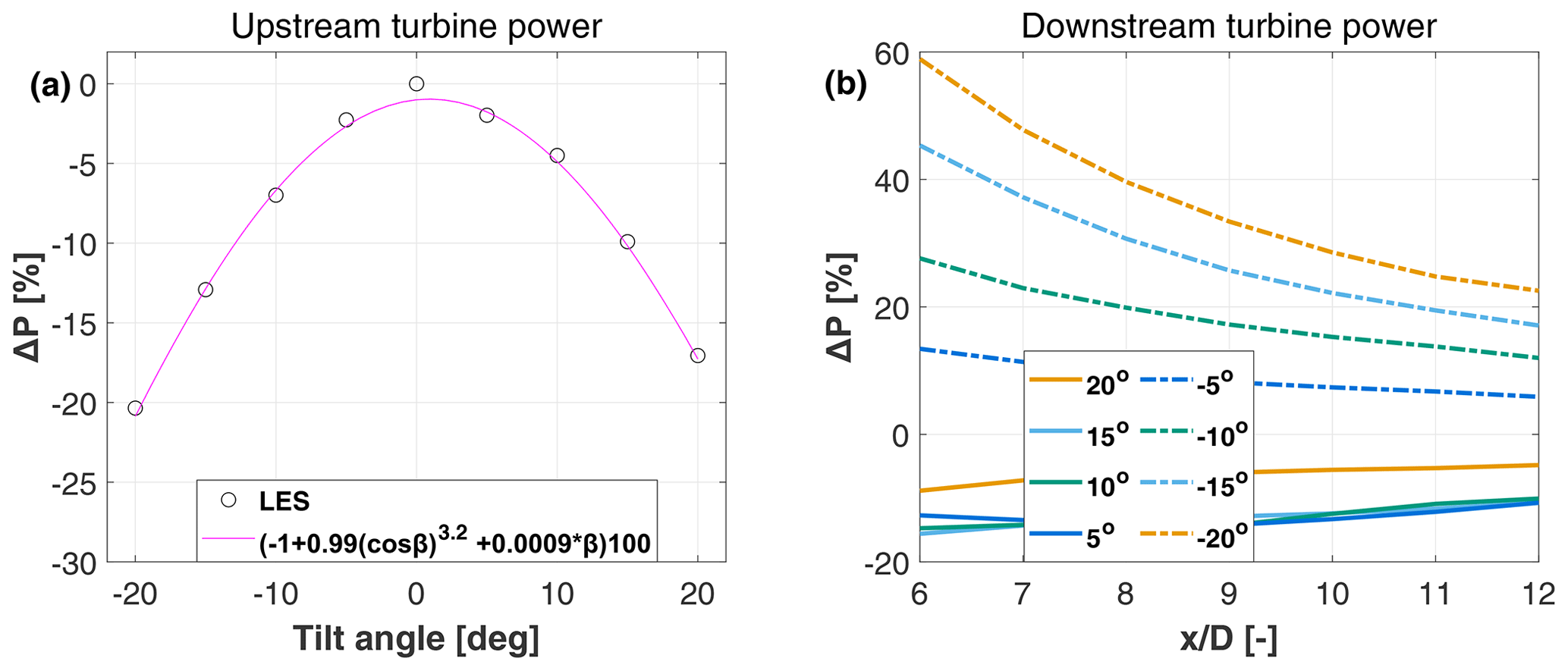
Figure 8Power drop as a function of the tilt angle for the wake-steering turbine (a). Power change in the wake as a function of the tilt angle and downstream distance (b).
Figure 8b shows the percent power change in the wake as a function of the upstream rotor tilt and downstream distance. For wake-down tilt angles, there is a substantial power gain due to the deflection of the wake out of the downstream rotor area, as shown in Fig. 5. The power gain grows with increasing tilt angles since the wake is further deflected out of the rotor area. At the same time, the upstream machine extracts less power from the flow, resulting in a slightly weaker wake. Furthermore, the power gain decreases with increasing turbine spacing because of wake recovery.
For wake-up tilt angles, the behavior of the power available in the wake is markedly different, and power drops for all tested tilt angles. In fact, as previously observed with the help of Fig. 6, the upper part of the wake recovers substantially faster than the lower part. Hence, by pushing the wake upwards, a lower-energy flow is moved into the rotor disk area, reducing power capture downstream.
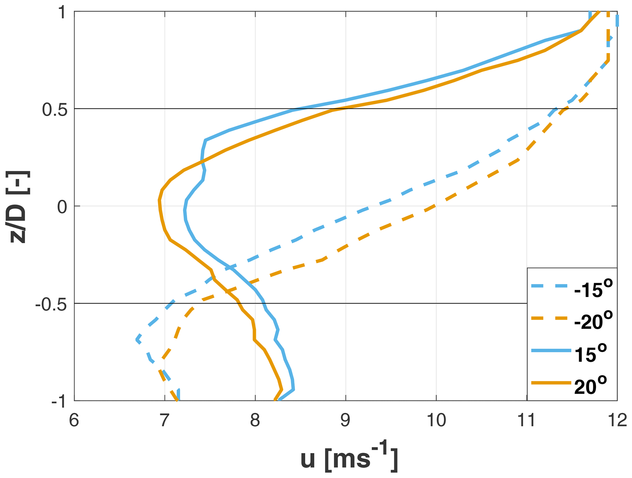
Figure 9Vertical profiles of the longitudinal speed in the wake at = 6 for various tilt angles. Black lines denote the rotor upper and lower edges.
Additionally, it appears that for wake-up tilt angles the power of the second wind turbine is fairly insensitive to the tilt misalignment of the upstream rotor, in contrast to the wake-down case. This effect can be explained with the help of Fig. 9, which shows vertical profiles of the streamwise velocity for various tilt angles at the hub center and = 6. The effect of increasing the tilt from −15 to −20∘ (wake-down) is quite clear, with the larger (negative) tilt angle leading to a higher speed within the rotor disk area. On the other hand, moving from 15 to 20∘ (wake-up) has a double-sided effect. On the one hand, the velocity drops in the upper part of the rotor disk area since the wake center is deflected further up. However, on the other hand the upstream machine extracts less energy from the flow, which results in higher speeds in the lower part of the rotor area. These two effects counteract each other, and, as a result, the power production of the downstream machine is relatively insensitive to the tilt angle for wake-up misalignments.
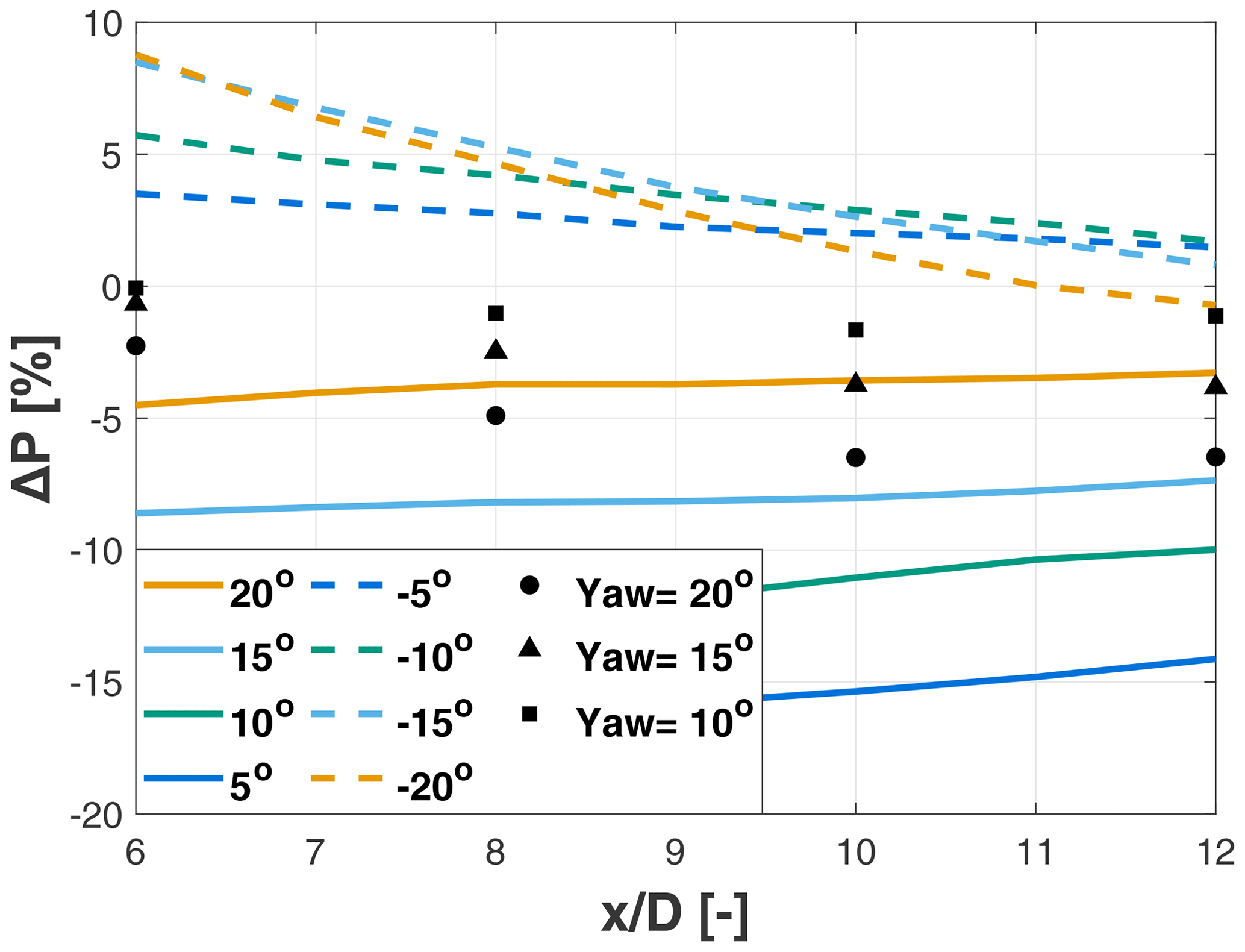
Figure 10Cluster power change as a function of the spacing between the turbines, for different tilt misalignment angles (solid and dashed lines). Black markers denote the change in cluster power for different yaw misalignment angles.
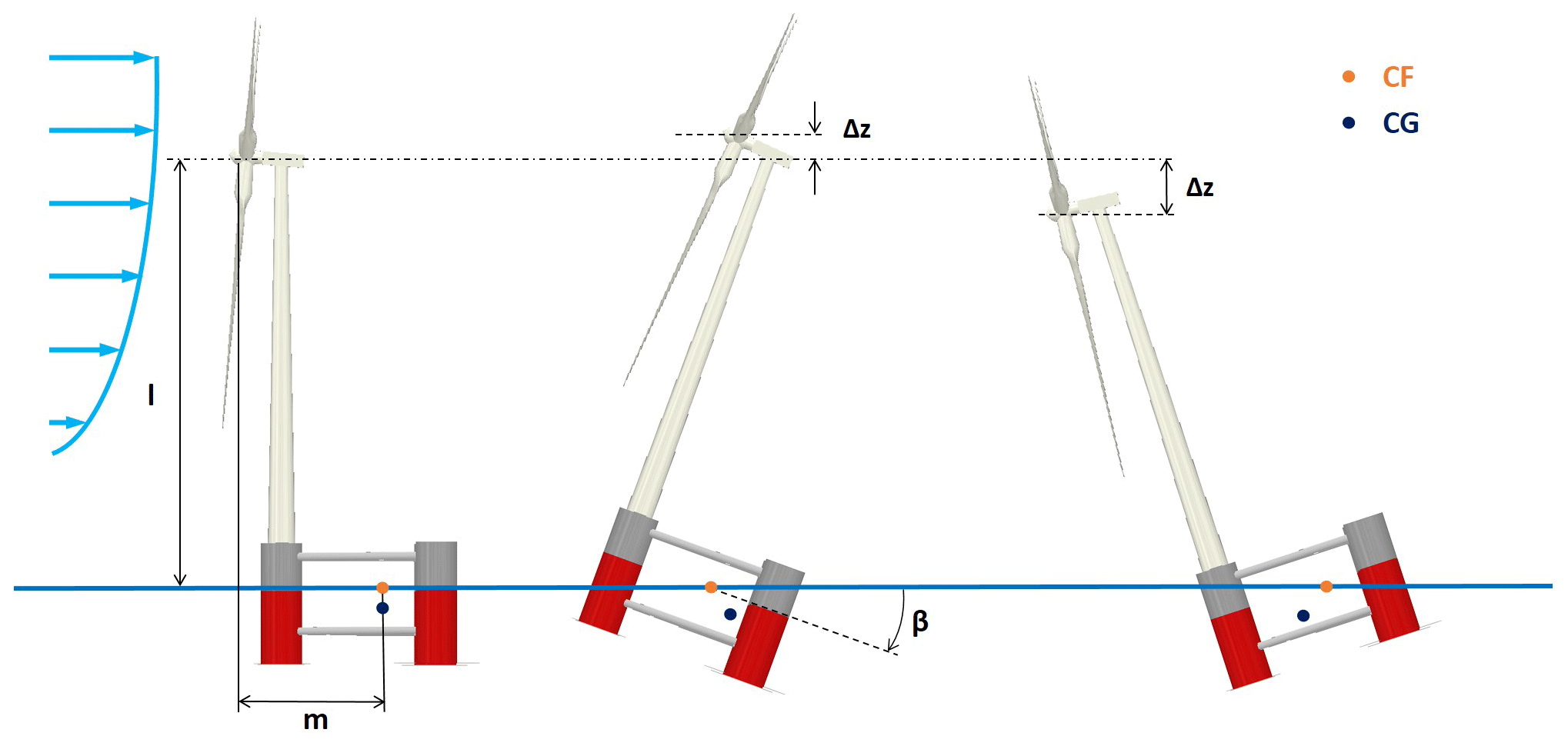
Figure 11Schematic representation of the effects of platform pitch on rotor hub height, considering Platform A. CF: center of flotation; CG: center of gravity; β: platform pitch angle.
Finally, it is interesting to consider the combined gain–loss effects on the power output of the two-turbine cluster, which are shown in Fig. 10. For wake-up tilt angles, the cluster power is always less than in the baseline untilted case; this is an expected result since, as shown in Fig. 8, tilt misalignment has a negative impact on both machines. For wake-down tilt angles, the power gain for longitudinal spacings between 10–12 D is around 2 %, while for closer spacings it can reach up to 8 %. The power gain is small but not negligible, considering the fact that it is observed in a cluster of only two turbines. In fact, previous research has shown that wake deflection strategies can multiply their impact in deep arrays (Annoni et al., 2017; Cossu, 2020, 2021a).
For a comparison with the more popular method of wind farm control by lateral wake deflection, the same simulation setup was used to implement lateral – as opposed to vertical – misalignment for three different yaw angles, namely 10, 15, and 20∘. The results are reported in Fig. 10 using black markers and indicate that – for similar misalignment angles – vertical deflection towards the ground outperforms lateral deflection. However, this finding is clearly setup specific, and different layouts and ambient conditions might lead to different results. This highlights another important consideration: the two techniques of lateral and vertical steering should not be seen as antagonistic, but rather they could be used together in synergy to achieve the best possible result depending on the layout and operating condition.
3.4 Effect of the configuration
The configuration of the floating platform may introduce additional parameters into the problem. For example, with reference to Platform A, pitching results in a vertical translation of the hub (see Fig. 11). The magnitude of this vertical translation Δz depends on the geometric characteristics of the platform-turbine assembly. For the case shown in the figure, the vertical displacement can be computed as
where m and l are the horizontal and vertical distances, respectively, between the hub and the center of rotation and β is the pitch angle of the platform (Fig. 11). The center of rotation is considered fixed at the centroid of the platform water-plane area (center of flotation – indicated as CF in the figure), which is a good approximation for small pitch angles (Newman, 2018). The vertical displacement also depends on the turbine orientation with respect to the platform (Fig. 12). For example, consider the situation of Fig. 11, which corresponds to orientation (a) of Fig. 12. In this case, the rotor center is translated downwards for a wake-down pitching of the platform. However, the opposite happens for orientation (c), where a wake-down pitching of the platform moves the rotor center upwards. Clearly, the ensuing effects on the rotor power and its wake also depend on the amount of shear of the inflow.
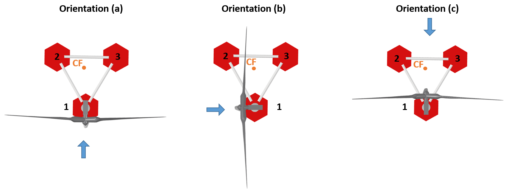
Figure 12Top view of three different turbine orientations with respect to the platform, in the case of Platform A. The blue arrow shows the incoming wind direction. Numbers identify the platform columns.
Figure 13a shows the relation between rotor tilt angle and the normalized vertical translation of the hub, for the three different turbine orientations of Fig. 12; these conditions provide an envelope within which all other possible conditions are contained. For Platform B, where the turbine is placed at the center of the floater, this effect is negligible, and all turbine orientations coincide (with a maximum 2 % deviation) with orientation (b) of Fig. 12.
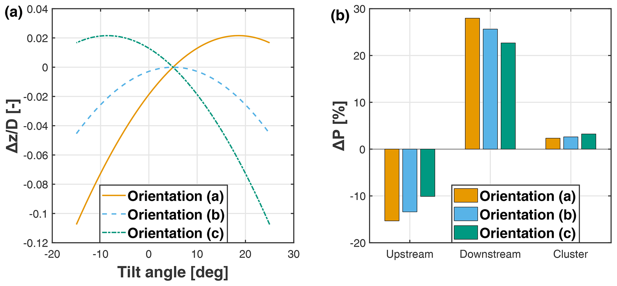
Figure 13Normalized vertical translation of the rotor center as a function of the rotor tilt angle for three different turbine orientations (a). Percent power change with respect to the baseline untilted case for a −10∘ (wake-down) deflection at a 10 D downstream distance, for three orientations of the turbine with respect to the floater (b).
The vertical translation of the hub caused by platform pitch can have two effects. First, it slightly shifts the wake position in the vertical direction. Second, in the case of a sheared inflow, it exposes the rotor to a slightly faster or slower wind speed. In the current setup and inflow conditions, it was found that the upstream machine loses approximately 5 % of power for a 0.1 D vertical movement towards the sea surface following an about 15∘ pitching. This loss of power is added to the one caused by tilt misalignment.
It is clear that these effects are strongly dependent on the turbine-platform configuration (for example, they are nearly absent for the Platform B case), operating conditions, and inflow. Therefore, it is difficult to provide a general assessment of their importance. However, in an effort to assess their potential relevance, it was decided to quantify their boundaries in the worst-case scenario of Platform A, where the position of the turbine at the very periphery of the floater exacerbates these effects. Figure 13b shows the percent power change with respect to the baseline untilted case for the upstream turbine, the downstream turbine, and the whole cluster. The spacing between the turbines is equal to 10 D. As expected, results indicate that the different turbine orientations have opposite effects on the upstream and downstream machines. For example, when compared to orientation (a), orientation (b) has a better performance for the upstream machine but a worse one for the downstream turbine. For the cluster power, orientation (c) exhibits the best results with a 2.6 % power increase, whereas orientation (b) and orientation (a) yield increases of 2.3 % and 2.0 %, respectively. These results apply to a sheared inflow exponent of 0.2 and would be correspondingly reduced/amplified by less/more pronounced shears.
The feasibility of the proposed vertical wake deflection technique was verified with respect to its effects on structural loading. The goal here is not to precisely characterize the loading of the pitched configurations but rather to reveal potential unrealistic load increases on the principal structural elements, which cannot be accommodated through confined design modifications.
4.1 Simulation setup
Structural loads were calculated with the comprehensive hydro-aero-servo-elastic analysis tool hGAST (Manolas et al., 2015; Manolas, 2015; Manolas et al., 2020) for the 10 MW reference turbine mounted on the tri-spar concrete floater (Platform B). Mooring lines were modeled using non-linear truss elements, without modifications with respect to the original mooring system of the floater. Load analyses were performed for the baseline untilted configuration and with the platform pitched by 20∘ in both wake-up and wake-down directions. The analysis considered medium sea-severity conditions, characterized by a 50-year significant wave height of 10.9 m, a peak period of 14.8 s, and a water depth of 180 m; typical offshore wind conditions were considered, characterized by high mean speeds and moderate turbulence levels, corresponding to wind class 1B.
Table 3Definition of DLCs for the time-domain hydro-aero-servo-elastic analysis. See the Appendix for definitions of the abbreviations.
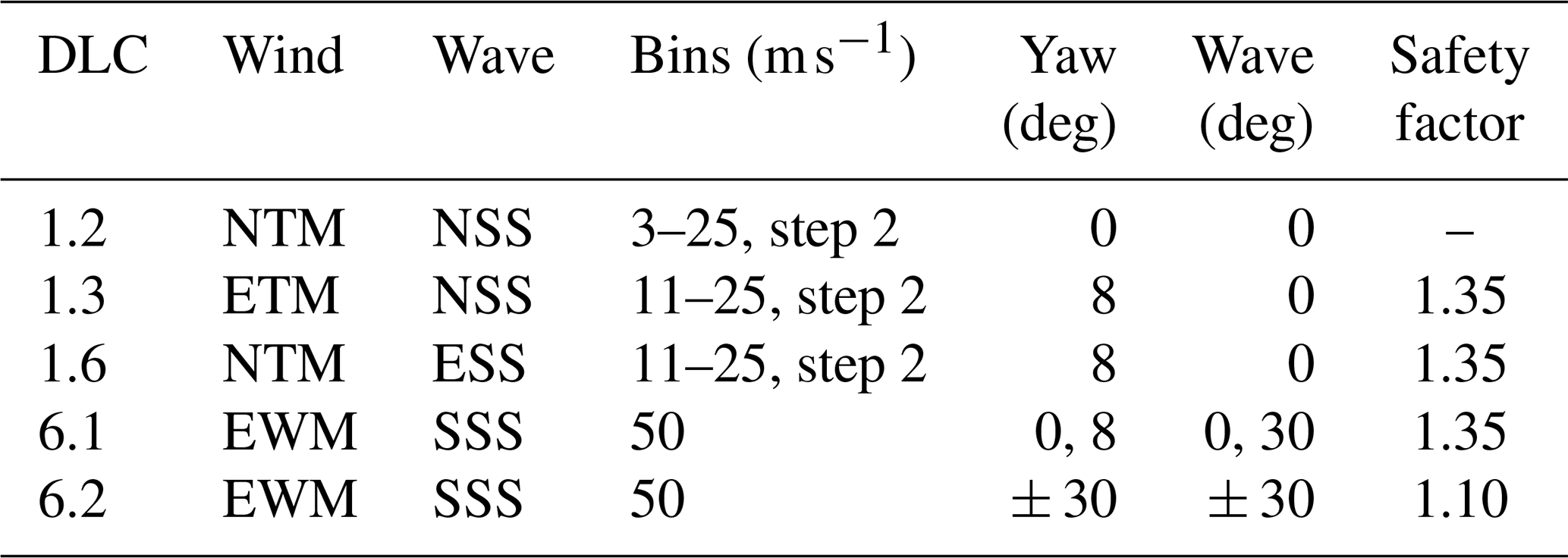
Simulations were conducted for a subset of the most critical design load cases (DLCs) of the IEC 61400-3 standard (IEC 61400-3-1:2019, 2008), including both extreme and fatigue conditions. The reduced test matrix is reported in Table 3.
A list of power production (normal operation) cases covering a wide operational range of wind and wave conditions are considered in the 1.x series. In the table, NTM and ETM refer to the normal and extreme turbulence models, respectively, while NSS and ESS refer to the normal and extreme sea states, respectively. Since wake steering is used only in the partial load region, power production simulations for the pitched platform case are performed for wind speeds up to 13 m s−1, to include the next speed bin just above rated (which is equal to 11.4 m s−1 for this turbine).
DLC 1.2 corresponds to normal operation of the floating turbine in normal turbulence and a normal sea state, and it is used for estimating the fatigue limit state (FLS). DLCs 1.3 and 1.6 correspond to extreme wind/wave conditions and are used to estimate the ultimate limit state (ULS). Clearly, there is no actual benefit in energy production from using wake-steering control when extreme wave conditions are anticipated or encountered (ESS conditions of DLC 1.6). Therefore, it is reasonable to assume that ballast control for wake steering is shut down in these conditions. Weather forecast and sensors (e.g., accelerometers, buoys) could be used to identify such conditions. However, since the response time of the control system is relatively slow (on the order of minutes, as indicated later in Sect. 5), DLC 1.6 was retained in the analyses to assess the effects of a system failure to set back the platform to its reference position in a timely manner.
DLCs 6.x correspond to operation under storm conditions, during which the turbine is in idling mode (combined with a grid loss in DLC 6.2). Typically, as a result of the loss of the grid, yaw control is disabled, possibly leading to extreme yaw misalignment angles. In many circumstances, such large angles drive the maximum loads on the rotor and the turbine. In the present analysis, misalignments of 0 and 8∘ in the wind direction and 0 and 30∘ in the wave direction were considered in DLC 6.1 (normal idling operation), while ± 30∘ wind misalignment and co-directional waves were considered in DLC 6.2 (idling operation combined with grid loss). It is noted that independent studies of an onshore version of the DTU 10 MW turbine have shown that yaw angles of ± 30∘ are the most critical in terms of maximum loads (Wang et al., 2017).
Table 4Eigenvalues (Hz) of the coupled floating system for three platform pitch angles (0, −20, and 20∘).
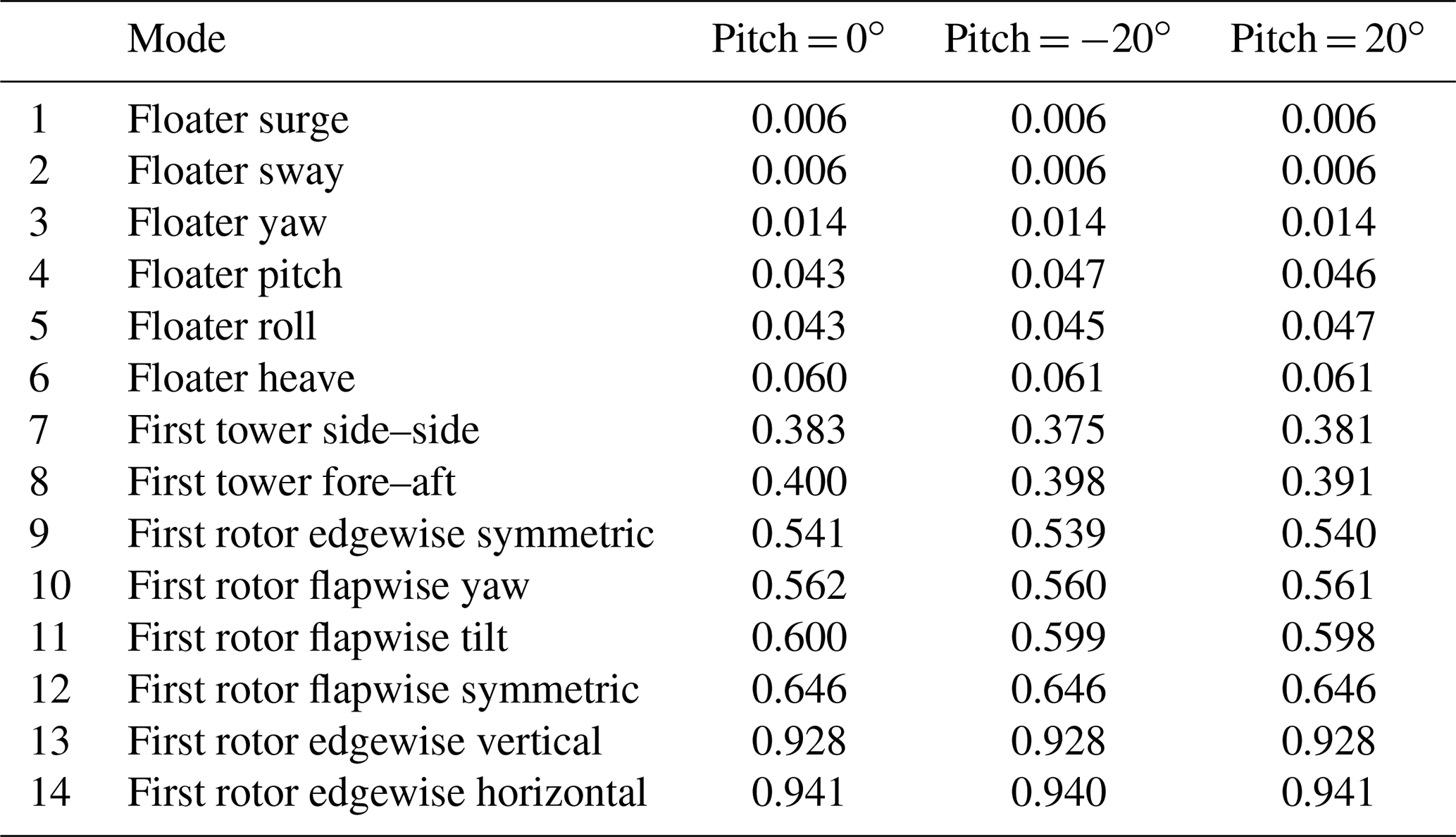
Before conducting the time-domain simulations, steady-state simulations were performed, considering only hydrostatics and gravity and no wind and wave excitation to estimate the required ballast movement and to confirm the hydrostatic stability of the tilted platform. Furthermore, a modal analysis of the overall system revealed that pitching induces extremely limited changes on the natural frequencies, as shown in Table 4.
The first-order hydrodynamic operators were re-calculated for both tilted floaters. The hydrodynamic problem considers the floater interacting with the incoming waves, and it is modeled using the hybrid integral equation method freFLOW (Manolas, 2015), which solves the 3D Laplace equation using the boundary element method in the frequency domain. The solution procedure provides the exciting loads, the added masses and damping coefficients, the response amplitude operators (RAOs) of the floater, and the hydrodynamic pressure on the wet surface of the floater, as well as the linearized hydrostatic stiffness matrix taking into consideration the exact “mean” geometry of the floater. Comparisons of the surge (Fsurge) and heave (Fheave) exciting force components and the pitch exciting moment (Mpitch) are shown in Fig. 14a–c. Results are normalized by gravity g, water density ρ, and wave amplitude A. The figure shows that the tilting of the floater (in either direction) has a relatively small effect on wave excitation loads. Higher localized differences (in the frequency range 0.5–1.5 rad s−1) are noted in the pitching moment and the heaving force. Moreover, the pitching of the floater in both directions increases the heave wave exciting loads by the pressure loads that are generated over the inclined cylindrical surfaces of the columns.
The system did not exhibit any dynamic instability for all simulated pitch angles and operating conditions. For DLC 1.6, which corresponds to an extreme sea state, the platform oscillated around a mean 20∘ pitch attitude with an oscillation amplitude of approximately 4∘. This showed that the system can reach approximately 24∘ of pitch without tipping over. However, a more complete analysis would be necessary to verify stability in other extreme conditions, such as sudden drops in the wind or emergency shutdowns, where rapid changes in thrust could in principle lead to even larger pitch angles.
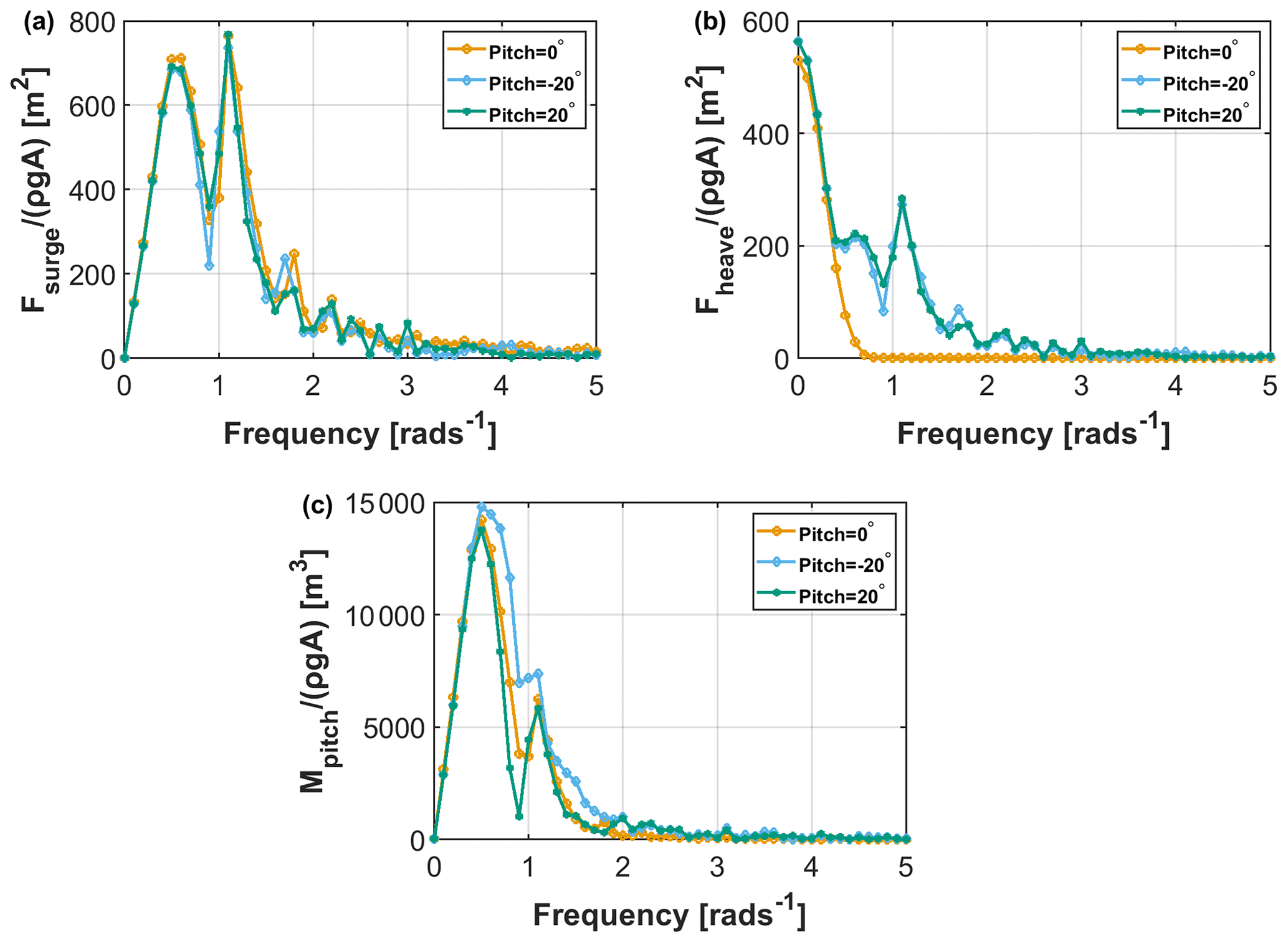
Figure 14Comparison of the wave exciting loads for platform pitch angles 0∘, 20∘ (wake-up), and −20∘ (wake-down). Surge (a); heave (b); pitch (c).
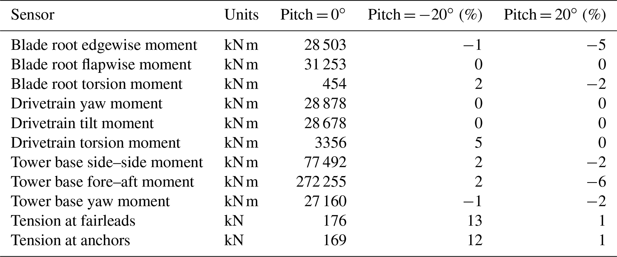
Table 5Comparison of lifetime DELs for platform pitch angles 0∘, 20∘ (wake-up), and −20∘ (wake-down).
4.2 Effects on damage equivalent and ultimate loads
Table 5 reports lifetime damage equivalent loads (DELs) of the two tilted configurations, comparing them with the ones of the untilted baseline case. DEL calculations are solely based on load time series from DLC 1.2, neglecting parked conditions and startup/shutdown sequences. Lifetime DELs are obtained considering a typical Weibull distribution with C = 11.3 m s−1 and k = 2, 107 reference cycles, and a lifetime of 20 years. The S–N curve exponents m = 4, m=8, and m=10 are used for the tower/mooring lines, drivetrain, and blades, respectively. Results indicate that blade, drivetrain, and tower FLS loads are barely affected by the tilting of the turbine in either direction. Overall, there is a slight reduction in the edgewise loads, which is higher (5 %) for wake-up pitching. This is explained by the fact that the component of the weight load in the rotor plane decreases as the turbine is tilted. The asymmetry between the wake-down and wake-up case is due to the built-in 5∘ uptilt angle of the rotor, which increases the overall rotor tilt for wake-up inclination of the turbine and vice versa. Flapwise bending moments remain unaffected. Tower bending moments slightly increase for wake-down pitching, whereas they slightly decrease for wake-up pitching. A maximum increase of 2 % is noted on tower base moments. Tower yaw moments slightly decrease in both configurations.
The main effect of pitching the platform is seen on the mooring line loads, specifically in the case of wake-down pitch. An increase of 13 % and 12 % is noted on the tension load at fairleads and at the anchor positions, respectively. On the other hand, only a minor increase of 1 % is observed for the wake-up pitch case. DEL estimates are derived by averaging over the three mooring lines.
Table 6Comparison of ultimate loads for platform pitch angle 0∘, 20∘ (wake-up), and −20∘ (wake-down).
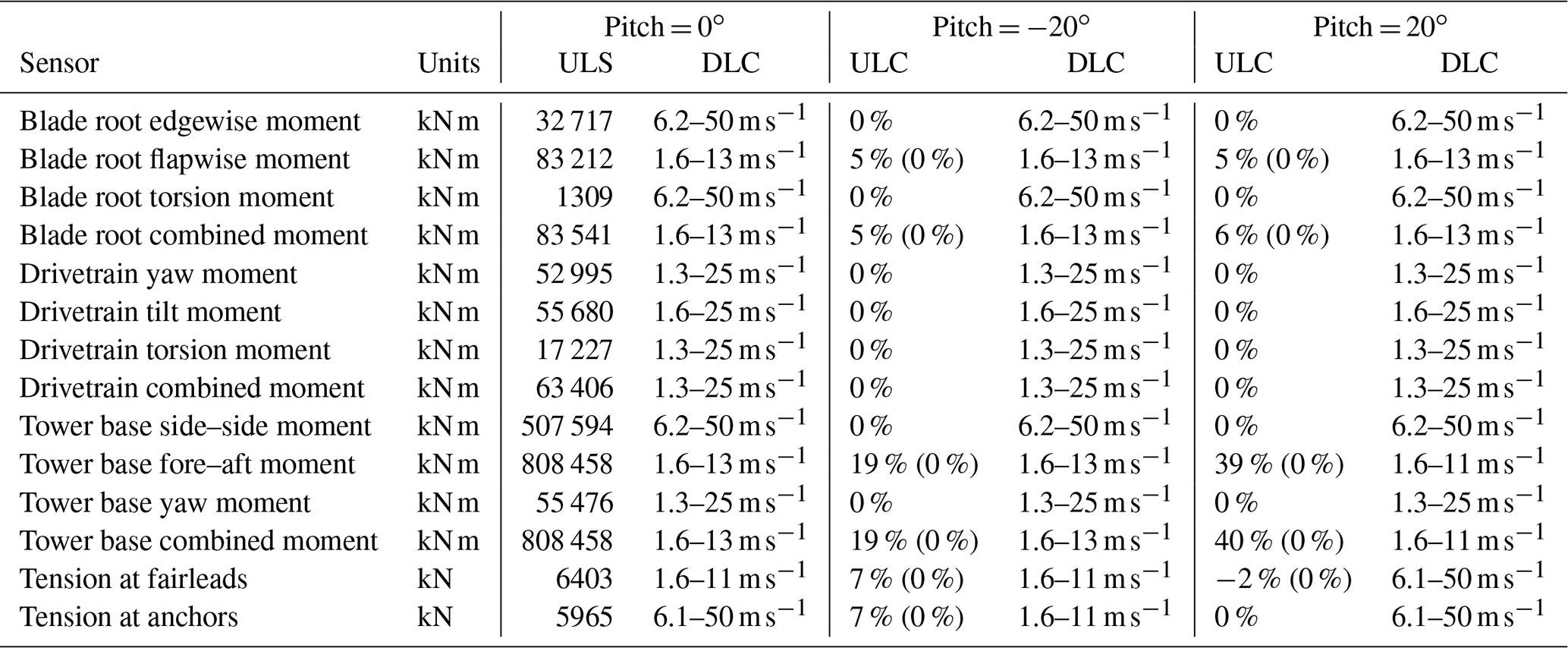
Regarding ultimate loads, it was found that in all cases loads were driven by DLCs outside of the operational envelope of the ballast control system (i.e., DLC 1.6 or DLC 6.x corresponding to the extreme sea state or parked/idling operation or at wind speeds higher than the wake-steering cutoff speed of 13 m s−1). Results are summarized in Table 6, which also reports the originating DLCs. Changes in loads are null for all cases where ULSs are found in DLCs other than 1.6 or 1.3 up to 13 m s−1 because the ballast control system is assumed to be deactivated in such conditions. When ultimate loads are originated in DLC 1.6, the load change obtained when this DLC is excluded has been indicated in parentheses.
Results show that blade extreme loads are only slightly affected by the platform pitching (maximum increase of 5 %–6 %), while drivetrain loads remain unaffected. Larger increases in ultimate loads are noted on tower bending moments. A 19 % increase in the combined bending moment is seen in the case of wake-down pitching, whereas a substantially higher increase (40 %) is seen in the case of wake-up pitching. The driving load case for tower base loads is DLC 1.6 around rated wind speed, for both the baseline and the pitched configurations. The difference between wake-down and wake-up pitch for the tower base fore–aft moment is due to the direction of thrust. For both pitch angles, the moment arm of the weight of the rotor nacelle assembly (RNA) increases, with a corresponding increase in the bending moment at the foot of the tower. However, the fore–aft moment due to the rotor thrust adds to the moment caused by the RNA weight for the wake-up pitch case, whereas it reduces the moment in the wake-down pitch case.
The tension of the mooring lines increases when the platform is pitched wake-down (by 7 %, caused by DLC 1.6), whereas it slightly decreases (by 2 %) in the case of wake-up pitching. In the latter case, the tension loads in the mooring lines obtained in DLC 1.6 are smaller than those obtained in DLC 6.1, which becomes the driving load case.
Overall the above results indicate that the ballast system should be deactivated when extreme wave conditions occur. This is especially true for the tower base bending moment, which experiences the highest increase. It is worth noting, however, that the observed 40 % load increase comes from the wake-up platform attitude, which, as shown in Sect. 3.3, is not capable of boosting power output. For the more interesting wake-down pitch case, the increase in tower-base combined moment is much more contained. Most importantly, based on the reasonable assumption that platform pitching is deactivated for DLC 1.6 conditions, it appears that ballast control will not increase the ultimate loads on the structure.
Next, the hydrostatics of floating bodies was used to estimate the differential ballast control necessary to pitch the two floating turbine configurations considered here. For a platform that is resting horizontally, all forces and moments are in equilibrium. If ballast is moved in a specific direction, the center of gravity will move accordingly. As a consequence, the platform will pitch, moving the center of buoyancy in the same direction, until a new equilibrium condition is reached (Patel, 1989). The calculations presented here are only indicative and, here again, specific to the configurations considered. For instance, some assumptions have to be made regarding the water ballast pumping system. Moreover, the orientation of the turbine with respect to the floater also plays a role for Platform A since the ballast movement required for orientation (b) is different from the one necessary for orientations (a) and (c) (see Fig. 12).
The analysis is performed for a rotor tilt angle of −15∘ (wake-down), which is the largest tilt angle (worst-case scenario) associated with significant power gains. Given the 5∘ uptilt of the DTU 10 MW turbine, the platform is pitched forward by 20∘ to achieve this attitude. Based on the findings of Sect. 3.4, for Platform A the analysis is conducted for orientation (c), which is the most beneficial case in terms of cluster power gain. As previously noted, due to the more symmetric configuration of Platform B, the turbine-platform orientation does not play a role in that case.
For Platform B, the necessary ballast movement was found from static simulations in horizontal and pitched attitudes using the hGAST software (Manolas et al., 2015; Manolas, 2015; Manolas et al., 2020).
Since a similar structural model of Platform A was not available, in this case ballast movement was estimated based on simpler equilibrium of forces and moments for the horizontal and pitched configurations. The analysis considered the mass distribution of the platform and of the turbine, the turbine thrust and torque, and the buoyancy forces from the three columns (Fig. 15). The forces transmitted to the platform by the mooring lines were neglected from the analysis, because the pitch and roll mooring stiffness is small for catenary lines compared to the hydrostatic and gravitational stiffness. This assumption was validated using hGAST for Platform B, where the mooring lines were found to contribute only 5 % of the total restoring force. Since no detailed design for Platform A was available, the precise displacement of the column center of gravity and buoyancy could only be estimated. However, the sensitivity of the results to these quantities is relatively low. For example, it was verified that, even with a 30 % deviation from the estimated values (which is an exaggerated assumption), the final results of the ballast calculations are affected by less than 4 %. To verify the calculation method used for Platform A, the same approach was also used for Platform B, and the results were compared to the ones obtained with the hGAST software, yielding only a 6 % difference. Such accuracy was deemed sufficient for the preliminary nature of the present investigation.
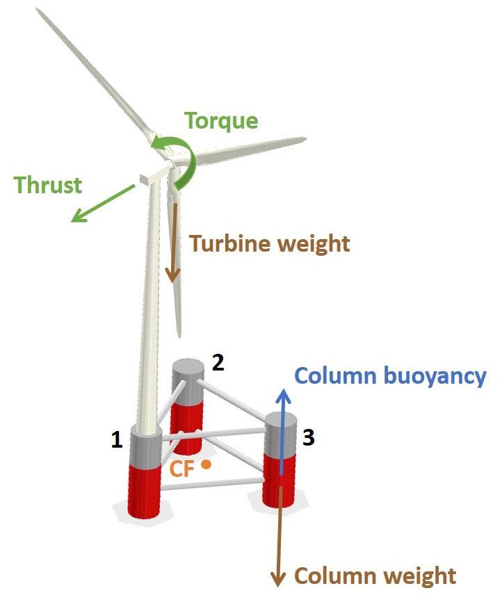
Figure 15Forces and moments considered for the ballast calculations. For clarity, only the forces on one of the columns are shown.
Results indicate that the necessary ballast movement to achieve a −20∘ wake-down pitch attitude for Platform A is approximately equal to 500 m3. Considering configuration (c) (Figs. 12c and 15), assuming that water can be moved between each column by dedicated 60 kW pumps, two pumps are used to move water in order to lift column 1 and sink columns 2 and 3. As the platform pitches towards a −20∘ attitude, a height difference between column 1 and columns 2–3 is created. This means that the ballast moves towards a lower position, which facilitates the maneuver. This change in attitude requires approximately 5 min and 2 kW h (Menon, 2004). When it is time to return the platform to the horizontal attitude, the situation is different since the ballast has to move to a higher position. In this case, the maneuver takes approximately 13 min and costs roughly 26 kW h.
For the same −20∘ wake-down pitch attitude, the ballast required for Platform B is equal to 2900 m3. Given the very large size and weight of this configuration, assuming pumps of triple the power of case A, the first maneuver (from a horizontal position to −20∘ pitch attitude) takes around 10 min, and the energy expenditure is about 13 kW h. The return to a horizontal attitude requires slightly more than 20 min and costs 132 kW h.
Considering two reference turbines spaced 10 rotor diameters apart, exposed to an ambient wind speed of 9 m s−1, the front turbine produces 5 MW and the downstream machine yields 3.5 MW. In such a condition, tilting the first turbine would improve the cluster power production by roughly 3 %, i.e., 250 kW (which is a conservative assumption, given the results of Sect. 3.4). Given that the relation between the tilt angle and power gain is approximately linear, Platform A and Platform B would need about 13 and 51 min, respectively, of tilted operation (including the transition time from horizontal to the target tilt angle) to break even with the energy expenditure caused by tilting and start having a net energy gain.
As previously mentioned, the orientation of the turbine with respect to the platform plays a role for Platform A. In fact, the ballast movement required for orientation (b) is 3 times larger than for orientations (a) and (c); this effect is however negligible for Platform B.
Notwithstanding the variety of possibilities and the room for further optimization, these results indicate that tilt control by differential ballast is a rather slow control input that should be activated in fairly steady wind conditions; possibly, faster changes in ambient conditions could be tracked by lateral yaw misalignment. Additionally, the characteristics of the platform also play a role, with heavy configurations being at a significant disadvantage.
This paper has presented a technical feasibility assessment of vertical wake steering for floating wind turbines. Today the most mature wind farm control approach is lateral wake steering, a method that is attracting significant attention as the wind energy community is trying to alleviate the adverse effects of turbine wake interaction within wind plants. One of the reasons for the success of lateral deflection is the fact that it can be implemented without a radical redesign of the turbine. The present study is an attempt to verify if a similar approach is also possible for vertical steering in floating turbines.
The study is based on two different floating platforms and one reference 10 MW wind turbine. These platforms feature ballast tanks for balancing the structure and incorporate an active ballast control system for keeping the platform aligned with the water surface (Roddier et al., 1997). The idea explored here is to reuse or adapt such systems in order to tilt the rotor and deflect the wake vertically.
Results obtained with a combined simulation–experimental study indicate that, for two aligned wind turbines spaced 10–12 diameters apart, power gains reach about 2.6 %, while for spacings of 6–8 diameters gains can increase to about 8 %, similarly to the findings of previous research (Annoni et al., 2017; Cossu, 2020; Bay et al., 2019). These gains are obtained with a −10∘ wake-down rotor tilt angle that corresponds, due to the rotor uptilt, to a −15∘ pitch forward of the platform. Because of the direction of rotor uptilt, smaller platform rotations would be necessary for downwind turbine configurations. Notwithstanding this possible advantage, downwind turbines were not considered in this work because they are effectively absent from the current market. However, they have other interesting characteristics for very large rotors that might possibly change this situation in the future (Loth et al., 2017).
The present study has only considered two turbines in full waked conditions, for a specific ambient shear and turbulence intensity. However, previous research has shown that power gains may further increase when considering a larger number of turbines and more complex configurations (Annoni et al., 2017; Cossu, 2020; Bay et al., 2019). In accordance with prior studies on vertical wake steering (Fleming et al., 2015; Annoni et al., 2017; Cossu, 2020), the present results confirm that deflecting the wake towards the sea surface is more effective than deflecting it towards the sky. In fact, wake recovery is not symmetric when the wake develops within a boundary layer. Due to the vertical non-uniformity of the free stream, turbulent mixing and recovery are faster in the top than in the bottom part of the wake. Therefore, deflecting the wake towards the sea surface results in an airflow of higher momentum moving downwards and into the downstream rotor disk area, thereby boosting capture; the opposite happens when the wake is deflected upwards, resulting in a slower flow being lifted up towards the downstream rotor. Additional intra-plant phenomena happen when considering larger arrays and more complex configurations (Cossu, 2020, 2021a), further increasing power capture.
Another conclusion of the present study is that the geometric characteristics of the platform can have a substantial effect. According to intuition, it was found that a steel platform with smaller draft requires much less ballast movement compared to a concrete platform with greater draft. Specifically, the lighter-weight three-floater configuration of Platform A is able to transition from a horizontal no-steering condition to full steering in about 5 min. For a two-turbine cluster, it would take about 13 min from the beginning of the maneuver to compensate for the expenditure due to tilting and start gaining power; on deeper arrays (Cossu, 2020, 2021a) this time might be substantially reduced because of the larger power gains. On the other hand, longer maneuvering times and higher energy expenditures penalize heavy large-draft configurations such as the one represented by Platform B. Ballast movement however also depends on additional details related to the geometry of the system. For example, the orientation of the turbine with respect to the platform can have an effect on ballast when the turbine is located directly above a column because of the strong inertial asymmetry that it creates. Additional effects are related to vertical movements of the hub caused by pitching, resulting in small changes in power capture for sheared flow conditions, which can be beneficial or detrimental depending on the direction of the vertical motion. A more comprehensive analysis, reflecting the latest and most promising configurations, is necessary before final conclusions can be drawn on whether ballast movement is a viable option for implementing vertical steering by pitching. However, this initial study seems to indicate that the amount of water that needs to be moved, the time it will take to pitch, and the energy that is required are not unrealistically high, at least for the lighter-weight Platform A configuration. The present results also indicate that a lightweight steel configuration (like Platform A) with a central arrangement of the turbine (like Platform B) might seem to offer an interesting solution, which is worth investigating in future studies.
Even in the most beneficial conditions, this preliminary analysis clearly shows that rotor tilting by differential ballast control is a relatively slow control input. Therefore, vertical steering by this method should probably be used only to follow slow changes in wind conditions. On the other hand, lateral steering is able to operate on somewhat faster timescales. This seems to give strong support for the study of integrated lateral–vertical steering control, which should try to combine these two complementary methods to maximize their synergies. Of course, steering is only one of the various wake manipulation techniques available, and it could be integrated with – for example – induction control. The optimal combination of techniques for affecting wake behavior is an active area of research in wind farm control, and further progress is anticipated.
Another key aspect related to the feasibility of the present wind farm control method is related to the loading experienced by the steering turbine. This problem was investigated by hydro-aero-servo-elastic simulations with reference to the Platform B concept, for which a complete structural model was available. This heavy platform with a large draft does not seem to be ideally suited to vertical steering because of the large ballast movements that it requires. In hindsight, a loading study of the lighter-weight Platform A would have been more appropriate; this was unfortunately not possible within the scope of the present project because a detailed design of the Platform A concept was not available. Loads were evaluated for 20∘ pitch-forward and pitch-backward attitudes, considering both fatigue and ultimate loads, and they were compared to the design loads of the floating system when it is operated without vertical wake steering. The comparison was made under the assumption that steering is used only up to speeds just above rated and that it would not be used in extreme sea and wind conditions. Regarding platform stability, it was found that the platform was hydrodynamically stable at the tested pitch angles even in extreme sea state conditions (DLC 1.6), although this system is not supposed to work in such conditions. This result is only indicative, and more exhaustive analyses are required to ensure that the platform can withstand, within the whole operational envelope, disturbances coming from, for instance, sudden wind drops, emergency shutdowns, or critical failures of some key components. A detection system with appropriate redundancy might possibly be used to forecast adverse weather conditions and ensure safe behavior in operation, although the characteristics of such a system were not considered in this work.
Results indicate that there is only a minor effect on turbine fatigue loads, with an increase of about 5 % being experienced by the drivetrain torsional moment. On the other hand, larger increases of about 12 %–13 % were noted on the mooring system, which would have to be accordingly redesigned. Ultimate loads were not affected, since – for this turbine and platform – they are all produced in operational conditions where wake steering is not utilized. These results are promising, but here again more specific analyses – including the case of a tilted and wake-impinged machine – are needed before more conclusive answers can be given.
| A | Wave amplitude |
| CP | Power coefficient |
| D | Rotor diameter |
| F | Force |
| M | Moment |
| g | Gravitational acceleration |
| p | Cosine law power loss exponent |
| P | Power |
| Rw | Wake recovery |
| U | Ambient wind speed (time averaged) |
| u | Streamwise velocity component (time averaged) |
| x | Streamwise coordinate (positive downstream) |
| y | Crosswind coordinate (positive left, |
| downstream) | |
| z | Vertical coordinate (positive up) |
| β | Platform pitch angle |
| ρ | Water density |
| ALM | Actuator line method |
| CFD | Computational fluid dynamics |
| CF | Center of flotation |
| DEL | Damage equivalent load |
| DLC | Design load case |
| ETM | Extreme turbulence model |
| EWM | Extreme wind model |
| FLS | Fatigue limit state |
| LES | Large-eddy simulation |
| NSS | Normal sea state |
| NTM | Normal turbulence model |
| S-PIV | Stereo particle image velocimetry |
| SSS | Severe sea state |
| ULS | Ultimate limit state |
Data from the CFD and hydro-aero-servo-elastic simulations are available upon request. MATLAB figure files that allow for the lossless extraction of results can be retrieved via https://doi.org/10.5281/zenodo.6799342 (Nanos et al., 2022b).
EMN conducted the experiments, contributed to the CFD simulations, performed all sizing analyses, and contributed to the interpretation of the results. CLB devised the original idea of vertical wake steering by differential ballast control, collaborated in the interpretation of the results, and supervised the overall work. ST contributed to the CFD simulations and data analysis. DIM and VAR performed the hydro-aero-servo-elastic analysis and contributed to the analysis of the loading conditions on the turbine. EMN and CLB wrote the manuscript, except for Sect. 4, which was primarily authored by DIM and VAR. All authors provided important input to this research work through discussions and feedback and by improving the manuscript.
At least one of the (co-)authors is a member of the editorial board of Wind Energy Science. The peer-review process was guided by an independent editor, and the authors also have no other competing interests to declare.
The authors would like to thank Helena Canet at TUM for her input on the load analysis and Antonis Daskalakis of Offshore Energy Systems SA for his advice on the platform sizing. Chengyu Wang and Filippo Campagnolo at TUM contributed to the work on the CFD simulations, while Giacomo Valerio Iungo, Kyle Jones, and Mario Rotea, all at UTD, supported the wind tunnel measurements at UTD. The authors express their appreciation to the Leibniz Supercomputing Centre (LRZ) for providing access and computing time on the SuperMUC Petascale System under Projekt-ID pr84be “Large-eddy Simulation for Wind Farm Control”.
This work was supported by the German Research Foundation (DFG) and the Technical University of Munich (TUM) in the framework of the Open Access Publishing Program.
This paper was edited by Alessandro Bianchini and reviewed by two anonymous referees.
Annoni, J., Scholbrock, A., Churchfield, M., and Fleming, P.: Evaluating tilt for wind plants, American Control Conference, 24–26 May 2017, Seattle, WA, USA, 717–722, https://doi.org/10.23919/ACC.2017.7963037, 2017. a, b, c, d, e, f
Azcona, J., Vittori, F., Schmidt, U., Savenije, F., Kapogiannis, G., Karvelas, C., Manolas, D. I., Voutsinas, S. G., Amann, F., Faerron-Guzman, R., and Lemmer, F.: D4.3.7: Design Solutions for 10 MW Floating Offshore Wind Turbines, Tech. rep., http://www.innwind.eu/ (last access: 31 July 2022), 2017. a, b
Bak, C., Zahle, F., Bitsche, R., Kim, T., Yde, A., Henriksen, L. C., Hansen, M. H., Blasques, J. P., Gaunaa, M., and Natarajan, A.: The DTU 10-MW Reference Wind Turbine, Danish Wind Power Research 2013, Technical University of Denmark, DTU Wind Energy, https://backend.orbit.dtu.dk/ws/portalfiles/portal/55645274/The_DTU_10MW_Reference_Turbine_Christian_Bak.pdf (last access: 31 July 2022), 2013. a
Bay, C. J., Annoni, J., Martínez-Tossas, L. A., Pao, L. Y., and Johnson, K. E.: Flow control leveraging downwind rotors for improved wind power plant operation, P. Amer. Contr. Conf., 20, 2843–2848, 2019. a, b
Burton, T., Sharpe, D., Jenkins, N., and Bossanyi, E.: Wind energy handbook, John Wiley & Sons, ISBN 13:978-1119451099, 2001. a
Campagnolo, F., Petrović, V., Schreiber, J., Nanos, E. M., Croce, A., and Bottasso, C. L.: Wind tunnel testing of a closed-loop wake deflection controller for wind farm power maximization, J. Phys. Conf. Ser., 753, 032006, https://doi.org/10.1088/1742-6596/753/3/032006, 2016a. a
Campagnolo, F., Petrović, V., Schreiber, J., Nanos, E. M., Croce, A., and Bottasso, C. L.: Wind tunnel testing of a closed-loop wake deflection controller for wind farm power maximization, J. Phys. Conf. Ser., 753, 032006, https://doi.org/10.1088/1742-6596/753/3/0320, 2016b. a
Campagnolo, F., Weber, R., Schreiber, J., and Bottasso, C. L.: Wind tunnel testing of wake steering with dynamic wind direction changes, Wind Energ. Sci., 5, 1273–1295, https://doi.org/10.5194/wes-5-1273-2020, 2020. a
Chamorro, L. P. and Porté-Agel, F.: A Wind-Tunnel Investigation of Wind-Turbine Wakes: Boundary-Layer Turbulence Effects, Bound.-Lay. Meteorol., 132, 129–149, https://doi.org/10.1007/s10546-009-9380-8, 2009. a
Cossu, C.: Replacing wakes with streaks in wind turbine arrays, Wind Energy, 24, 345–356, https://doi.org/10.1002/we.2577, 2020. a, b, c, d, e, f, g, h
Cossu, C.: Evaluation of tilt control for wind-turbine arrays in the atmospheric boundary layer, Wind Energ. Sci., 6, 663–675, https://doi.org/10.5194/wes-6-663-2021, 2021a. a, b, c, d, e, f
Cossu, C.: Wake redirection at higher axial induction, Wind Energ. Sci., 6, 377–388, https://doi.org/10.5194/wes-6-377-2021, 2021b. a
Doekemeijer, B. M., Kern, S., Maturu, S., Kanev, S., Salbert, B., Schreiber, J., Campagnolo, F., Bottasso, C. L., Schuler, S., Wilts, F., Neumann, T., Potenza, G., Calabretta, F., Fioretti, F., and van Wingerden, J.-W.: Field experiment for open-loop yaw-based wake steering at a commercial onshore wind farm in Italy, Wind Energ. Sci., 6, 159–176, https://doi.org/10.5194/wes-6-159-2021, 2021. a, b, c
Fleming, P., Gebraad, M., Lee, S., van Wingerden, J., Johnson, K., Churchfield, M., Michalakes, J., Spalart, P., and Moriarty, P.: Simulation comparison of wake mitigation control strategies for a two-turbine case, Wind Energy, 18, 2135—-2143, https://doi.org/10.1002/we.1810, 2015. a, b, c, d
Fleming, P., Annoni, J., Churchfield, M., Martinez-Tossas, L. A., Gruchalla, K., Lawson, M., and Moriarty, P.: A simulation study demonstrating the importance of large-scale trailing vortices in wake steering, Wind Energ. Sci., 3, 243–255, https://doi.org/10.5194/wes-3-243-2018, 2018. a
Fleming, P., King, J., Dykes, K., Simley, E., Roadman, J., Scholbrock, A., Murphy, P., Lundquist, J. K., Moriarty, P., Fleming, K., van Dam, J., Bay, C., Mudafort, R., Lopez, H., Skopek, J., Scott, M., Ryan, B., Guernsey, C., and Brake, D.: Initial results from a field campaign of wake steering applied at a commercial wind farm – Part 1, Wind Energ. Sci., 4, 273–285, https://doi.org/10.5194/wes-4-273-2019, 2019. a, b, c
Fleming, P., King, J., Simley, E., Roadman, J., Scholbrock, A., Murphy, P., Lundquist, J. K., Moriarty, P., Fleming, K., van Dam, J., Bay, C., Mudafort, R., Jager, D., Skopek, J., Scott, M., Ryan, B., Guernsey, C., and Brake, D.: Continued results from a field campaign of wake steering applied at a commercial wind farm – Part 2, Wind Energ. Sci., 5, 945–958, https://doi.org/10.5194/wes-5-945-2020, 2020. a, b
Frederik, J. A., Doekemeijer, B. M., Mulders, S. P., and van Wingerden, J.-W.: The helix approach: Using dynamic individual pitch control to enhance wake mixing in wind farms, Wind Energy, 23, 1739–1751, https://doi.org/10.1002/we.2513, 2020a. a
Frederik, J. A., Weber, R., Cacciola, S., Campagnolo, F., Croce, A., Bottasso, C., and van Wingerden, J.-W.: Periodic dynamic induction control of wind farms: proving the potential in simulations and wind tunnel experiments, Wind Energ. Sci., 5, 245–257, https://doi.org/10.5194/wes-5-245-2020, 2020b. a
Guntur, S., M., J. J., B., J., Q., W., Sprague, A., M., Sievers, R., and Schrek, S. J.: FAST v8 verification and validation for a MW-scale wind turbine with aeroelastically tailored blades, Wind Energy Symp., 2016. a
IEC 61400-3-1:2019 Wind energy generation systems – Part 3-1: Design requirements for fixed offshore wind turbines. https://webstore.iec.ch/publication/29360 (last access: 31 July 2022), 2008. a
Jasak, H.: OpenFoam: opeN source CFD in research and industry, Int. J. Nav. Arch. Ocean, 1, 89–94, https://doi.org/10.3744/JNAOE.2009.1.2.089, 2009. a
Liu, Y., Li, S., Yi, Q., and Chen, D.: Developments in semi-submersible floating foundations supporting wind turbines: A comprehensive review, Renew. Sust. Energ. Rev., 60, 433–449, 2016. a
Loth, E., Steele, A., Qin, C., Ichter, B., Selig, M. S., and Moriarty, P.: Downwind pre-aligned rotors for extreme-scale wind turbines, Wind Energy, 20, 1241–1259, https://doi.org/10.1002/we.2092, 2017. a
Manolas, D. I.: Hydro-aero-elastic analysis of offshore wind turbines, PhD thesis, National Technical University of Athens, https://dspace.lib.ntua.gr/xmlui/handle/123456789/42037?show=full (last access: 31 July 2022), 2015. a, b, c
Manolas, D. I., Riziotis, V. A., and Voutsinas, S. G.: Assessing the importance of geometric non-linear effects in the prediction of wind turbine blade loads, J. Comput. Nonlinear Dyn., 10, 041008, https://doi.org/10.1115/1.4027684, 2015. a, b
Manolas, D. I., Karvelas, C. G., Kapogiannis, I. A., Riziotis, V. A., Spiliopoulos, K. V., and Voutsinas, S. G.: A comprehensive method for the structural design and verification of the INNWIND 10MW tri-spar floater, J. Phys. Conf. Ser., 1104, 53023811, https://doi.org/10.1088/1742-6596/1104/1/012025, 2018. a, b
Manolas, D. I., Riziotis, V. A., Papadakis, G. P., and Voutsinas, S. G.: Hydro-servo-aero-elastic analysis of floating offshore wind turbines, Fluids, 5, 200, https://doi.org/10.3390/fluids5040200, 2020. a, b
Menon, S.: Piping Calculations Manual, McGraw-Hill Education, ISBN 978-0071440905, 2004. a
Munters, W. and Meyers, J.: Towards practical dynamic induction control of wind farms: analysis of optimally controlled wind-farm boundary layers and sinusoidal induction control of first-row turbines, Wind Energ. Sci., 3, 409–425, https://doi.org/10.5194/wes-3-409-2018, 2018. a
Nanos, E., Robke, J., Heckmeier, F., Cerny, M., Jones, K., Iungo, V., and Bottasso, C.: Wake characterization of a multipurpose scaled wind turbine model, AIAA Scitech 2019 Forum, 7–11 January 2019, San Diego, California, https://doi.org/10.2514/6.2019-2082, 2019. a
Nanos, E., Letizia, S., Barreiro, D., Wang, C., Rotea, M., Iungo, V., and Bottasso, C.: Vertical wake deflection for offshore floating wind turbines by differential ballast control, J. Phys. Conf. Ser., 23, 513–519, https://doi.org/10.1007/s003480050142, 2020. a, b
Nanos, E. M., Kheirallah, N., Campagnolo, F., and Bottasso, C. L.: Design of a multipurpose scaled wind turbine model, J. Phys. Conf. Ser., 1037, 052016, https://doi.org/10.1088/1742-6596/1037/5/052016, 2018. a
Nanos, E. M., Bottasso, C. L., Campagnolo, F., Mühle, F., Letizia, S., Iungo, G. V., and Rotea, M. A.: Design, steady performance and wake characterization of a scaled wind turbine with pitch, torque and yaw actuation, Wind Energ. Sci., 7, 1263–1287, https://doi.org/10.5194/wes-7-1263-2022, 2022. a, b, c, d, e
Nanos, E. M., Bottasso, C. L., Tamaro, S., Manolas, D. I., and Riziotis, V. A.: Vertical wake deflection for floating wind turbines by differential ballast control, Zenodo [data set], https://doi.org/10.5281/zenodo.6799342, 2022b. a
Newman, J.: Marine Hydrodynamics, in: 40th anniversary edition, MIT Press, ISBN 9780262534826, 2018. a
Parkin, P., Holm, R., and Medici, D.: The application of PIV to the wake of a wind turbine in yaw, DLR-Mitteilung, 3, 155–162, QC 20101018, 2001. a
Patel, M.: Dynamics of Offshore structures, [S.l.], Butterworth-Heinemann, ISBN 13:978-0408010740, 1989. a
Roddier, D., Cermelli, C., and Weinstein, A.: Windfloat: A Floating Foundation for Offshore Wind Turbines Part I: Design Basis and Qualification Process, in: Proc. of the ASME 2009 28th Int. Conf. on Ocean, 31 May–5 June 2009, Honolulu, 845–853, 1997. a, b, c, d
Scott, R., Bossuyt, J., and Cal, R.: Characterizing tilt effects on wind plants, J. Renew. Sustain. Ener., 12, 2135–2143, https://doi.org/10.1063/5.0009853, 2020. a, b, c, d
Siemens Gamesa Renewable Energy: https://www.siemensgamesa.com/en-int/newsroom/2019/11/191126-siemens-gamesa-wake-adapt-en (last access: 31 July 2022), 2019. a
Srinivas, G., Troldborg, N., and Gaunaa, M.: Application of engineering models to predict wake deflection due to a tilted wind turbine, in: European Wind Energy Conference and Exhibition, 16–19 April 2012, Bella Center, Copenhagen, Denmark, EWEC 2012, 2012. a
Steinbuch, M., de Boer, W., Bosgra, O., Peters, S., and Ploeg, J.: Optimal control of wind power plants, J. Wind Eng. Ind. Aerod., 27, 237–246, https://doi.org/10.1016/0167-6105(88)90039-6, 1988. a
Su, K. and Bliss, D.: A numerical study of tilt-based wake steering using a hybridfree-wake method, Wind Energy, 23, 258–273, https://doi.org/10.1002/we.2426, 2019. a
van der Hoek, D., Kanev, S., Allin, J., Bieniek, D., and Mittelmeier, N.: Effects of axial induction control on wind farm energy production – A field test, Renew. Energ., 140, 994–1003, https://doi.org/10.1016/j.renene.2019.03.117, 2019. a
Vermeer, L. J., Sørensen, J. N., and Crespo, A.: Wind turbine wake aerodynamics, Prog. Aerosp. Sci., 39, 467–510, https://doi.org/10.1016/S0376-0421(03)00078-2, 2003. a
Wang, C., Campagnolo, F., Sharma, A., and Bottasso, C.: Effects of dynamic induction control on power and loads, by LES-ALM simulations and wind tunnel experiments, J. Phys. Conf. Ser., 1619, 022036, https://doi.org/10.1088/1742-6596/1618/2/022036, 2020. a
Wang, C., Campagnolo, F., Canet, H., Barreiro, D. J., and Bottasso, C. L.: How realistic are the wakes of scaled wind turbine models?, Wind Energ. Sci., 6, 961–981, https://doi.org/10.5194/wes-6-961-2021, 2021. a
Wang, J., Wang, C., Campagnolo, F., and Bottasso, C. L.: Wake behavior and control: comparison of LES simulations and wind tunnel measurements, Wind Energ. Sci., 4, 71–88, https://doi.org/10.5194/wes-4-71-2019, 2019. a
Wang, K., Riziotis, V. A., and Voutsinas, S. G.: Aeroelastic stability of idling wind turbines, Wind Energ. Sci., 2, 415–437, https://doi.org/10.5194/wes-2-415-2017, 2017. a
- Abstract
- Introduction
- Reference turbine and platforms
- Characterization of the wake
- Assessment of fatigue and ultimate loads
- Ballast movement estimate
- Conclusions
- Appendix A: Nomenclature
- Code and data availability
- Author contributions
- Competing interests
- Acknowledgements
- Financial support
- Review statement
- References