the Creative Commons Attribution 4.0 License.
the Creative Commons Attribution 4.0 License.
 | 11 Mar 2022
Load reduction for wind turbines: an output-constrained, subspace predictive repetitive control approach
Riccardo Ferrari
Jan-Willem van Wingerden
Individual pitch control (IPC) is a well-known approach to reduce blade loads on wind turbines. Although very effective, IPC usually requires high levels of actuator activities, which significantly increases the pitch actuator duty cycle (ADC). This will subsequently result in an increase of the wear on the bearings of the blades and a decrease of the wind turbine reliability. An alternative approach to this issue is to reduce the actuator activities by incorporating the output constraints in IPC. In this paper, a fully data-driven IPC approach, which is called constrained subspace predictive repetitive control (cSPRC), is introduced. The output constraints can be explicitly considered in the control problem formulation via a model predictive control (MPC) approach. The cSPRC approach will actively produce the IPC action for the necessary load reduction when the blade loads violate the output constraints. In this way, actuator activities can be significantly reduced. Two kinds of scenarios are simulated to illustrate the unique applications of the proposed method: wake–rotor overlap and turbulent sheared wind conditions. Simulation results show that the developed cSPRC is able to account for the output constraints into the control problem formulation. Since the IPC action from cSPRC is only triggered to prevent violating the output constraints, the actuator activities are significantly reduced. This will help to reduce the pitch ADC, thus leading to an economical viable load control strategy. In addition, this approach allows the wind farm operator to design conservative bounds to guarantee the safety of the wind turbine control system.
- Article
(1398 KB) - Full-text XML
- BibTeX
- EndNote


Over the past decades, wind energy has expanded by leaps and bounds in the international energy mix (van Kuik et al., 2016). In total, 90 GW of new wind energy capacity was installed in 2020, which shows a rapid growth of 53 % compared to 2019 (Global Wind Energy Council, 2021).
However, one of the main challenges in the development of wind farms is the high operation and maintenance (O & M) cost (Willis et al., 2018). This is usually related to the design of the wind turbine which is subjected to severe dynamic loading. In particular, in a wind farm downstream turbines will be affected by the wake flow of the neighboring upstream turbines. The interaction between wake and turbines will lead to increased blade loads and loss of power (Frederik et al., 2020b). Also novel wake mixing strategies such as the HELIX can impose additional periodic structural loading (Frederik et al., 2020a). In addition, atmospheric turbulence will have a negative impact on the wind turbine performance (Barthelmie et al., 2007). Since wind turbines tend to have larger rotor diameters and a more slender tower than land-based counterpart, the effects of these dynamic loading would be more significant. Therefore, load mitigation concerning the wind turbines erected in a wind farm becomes of vital importance to guarantee the reliability of the turbine system and to reduce the O&M costs (Njiri and Söffker, 2016). In general, the majority of the loads on wind turbine rotors show a periodic nature (Liu et al., 2022a, b, 2021d). Individual pitch control (IPC) has demonstrated its effectiveness in reduction of these periodic loads (Bossanyi, 2003). In IPC, the pitch angle of each blade is regulated independently with the aid of individual pitch actuators and measurements of the bending moments. By superimposing the periodic pitch angles to each blade on top of the collective pitch, the blade loads can be alleviated.
Bossanyi (2003) initially demonstrated the possibility of reducing the blade loads occurring at an angular frequency of once per (1P) rotation, by using an IPC based on a linear quadratic Gaussian (LQG) approach. However, the 1P loads are symmetric and thus are not the dominant loads on the non-rotating components of the wind turbine. These components suffer from the largest loads at the blade passing frequency NP (e.g., 3P for a three-bladed wind turbine). Therefore, the Coleman transformation (Bir, 2008), which converts the loads from the rotating frame of reference into the static frame, was suggested. This makes it possible to use simple linear single-input and single-output (SISO) control approaches for IPC, such as proportional–integral (PI) controllers (Bossanyi, 2005; van Solingen et al., 2014). More recently, other advanced IPC approaches, such as fixed-structure H∞ feedback–feedforward IPC (Ungurán et al., 2019) and multivariable robust IPC (Yuan et al., 2020), were developed to mitigate the blade loads on the wind turbine. On the other hand, the application of IPC to wake load control in a wind farm is receiving increasing attention (Knudsen et al., 2015). However, the wind farm wake shows a more challenging characteristic, namely the wake meandering (Larsen et al., 2008), which was not considered in the developed approach. In order to address the challenge of such a complex wake meandering phenomenon, a new IPC, which is based on a multiple model predictive control (MPC) approach, was proposed by Yang et al. (2015).
The drawback of these approaches is that the pitch actuator duty cycle (ADC) is dramatically increased due to the cyclic fatigue loads on the pitch actuators. Such an effect is worsened when these approaches attempt to control the non-deterministic wind loads at high wind turbulence intensities and the dynamic loading caused by the wake. This will result in an increase of the wear on the bearings of the blades and eventually a shortening of the lifespan of the pitch control system. Moreover, the pitch control system is usually subjected to various constraints due to the physical restrictions of the pitch actuator, safety limitations, environmental regulations and wind farm manufacturer specifications (Vali et al., 2016). Exceeding these constraints may result in damage to the pitch control system and ultimately in the failure of the entire wind turbine.
In order to address this challenge, a constrained IPC was recently developed by Petrović et al. (2021). In their work, the input constraints of the pitch actuators are explicitly taken into account by using an MPC framework, which makes it possible to reduce the actuator activities. However, output constraints, to the best of authors' knowledge, have not been investigated yet for the case of IPC. As a control system with output constraints is capable of limiting the loads within certain safety bounds, it would be an ideal way to reduce the actuator activities. The widely used PI-based IPC augmented with some deadbands might be able to take into account the output constraints, while the tuning procedure of the parameters is rather cumbersome. Moreover, the multi-blade coordinate (MBC)-based IPC could be also potentially extended to limit ADC by manipulating the input signals of inverse Coleman transformation through suitable wind-up filters. Unfortunately, there are a limited number of publications investigating such output-constrained control strategies. Compared to the widely used input constraints, the inclusion of output constraints is more challenging. It may lead to an unstable, closed-loop system even though the corresponding unconstrained algorithm is stable (Wang, 2009).
In order to approach the goal of introducing output constraints in wind turbine control, a novel IPC approach is presented in this paper. It is based on a constrained subspace predictive repetitive control (cSPRC). The basic concept of SPRC was initially proposed by van Wingerden et al. (2011). It is essentially a fully data-driven approach comprised of subspace identification and repetitive control. The subspace identification step, based on an online solution, is used to recursively derive a linear approximation of the wind turbine dynamics (van der Veen et al., 2013). Based on it, a predictive repetitive control law is then formulated to reduce only specific deterministic loads, such as 1P loads, under varying operating conditions. The SPRC approach has shown promising results in numerical simulations (Navalkar et al., 2014; Liu et al., 2020a, b, 2021b, a) and in wind tunnel experiments (Navalkar et al., 2015; Frederik et al., 2018).
The main contributions of this paper lie in the following two aspects. The first contribution is the data-driven framework. For the first time, the constraints of the control problem, especially the output constraints of the blade loads, are explicitly considered in the repetitive control formulation. This is achieved by integrating an MPC approach (Qin and Badgwell, 2003) into SPRC, so that the repetitive control law subjected to specified output constraints can be formulated. Since the accuracy of the control output prediction is affected by the model uncertainty of the identified model, the output constraints may cause instability of the closed-loop system and severe deterioration of the control performance (Wang, 2009). Therefore, the output constraints are implemented as soft constraints by introducing so-called slack variables in the control problem formulation. The output constraints will be relaxed if the slack variables become large enough. In case there are no constraint violations, only the widely used baseline pitch controller is active to maintain basic wind turbine performance. Once the blade loads induced by the wind turbulence and wind farm wake increase and violate the output constraints, cSPRC will actively produce the IPC action for the necessary load mitigation. This is achieved by penalizing the control inputs only in the control objectives, which ensures that the controller will be inactive if the blade loads are lower than the safety bounds. Moreover, the safety bounds, corresponding to the values of the output constraints in cSPRC, can be designed according to the design regulations of wind farms, such as IEC 61400-1 (IEC, 2005). Since cSPRC is only enabled for necessary load reduction, the pitch activities would be significantly reduced while the safety of the wind turbine can be still guaranteed.
The second contribution is the unique application of the cSPRC approach to two independent scenarios: one where the wind turbine is impinged and overlapped by the wake shed from the upstream turbine and one where the turbulent sheared wind condition is present, respectively. In particular, in the wind farm wake scenario the wind turbine will experience partial and full wake overlap due to the wind direction change and the yaw misalignment of the upstream turbine (Fleming et al., 2015). The partial wake overlap, together with the velocity deficit within the wake, will induce asymmetric loading of the rotor plane of the wind turbine. This will vividly illustrate the capability of dealing with output constraints in the cSPRC approach.
The effectiveness of the cSPRC approach under these two typical scenarios will be demonstrated through high-fidelity simulations. For this, the FLOw Redirection and Induction in Steady-state (FLORIS) model (Gebraad et al., 2016), which is a parametric model for predicting a steady-state wake in a wind farm, is utilized to simulate the wind farm wake. It actually provides the wind speed input for the wind turbine simulations. Then, the wind turbine simulations are executed using the US National Renewable Energy Laboratory (NREL)'s Fatigue, Aerodynamics, Structures, and Turbulence (FAST) tool (Jonkman and Buhl, 2005). In this respect, a 10 MW wind turbine model is used, which is developed by the Technical University of Denmark (DTU) (Bak et al., 2013) and the Stuttgart Wind Energy (SWE) institute (Lemmer et al., 2016). A thorough comparison against baseline and conventional IPC approaches is made to evaluate the performance of the proposed cSPRC.
The remainder of this paper is organized as follows. Section 2 introduces the wind turbine model and the simulation environment. In Sect. 3, the methodology of the cSPRC with the inclusion of output constraints is elaborated. Then, the potential of cSPRC for load mitigation in wake–rotor overlap and turbulent sheared wind scenarios is illustrated through high-fidelity simulations in Sect. 4. Conclusions are drawn and future work is discussed in Sect. 5.
In this section, the wind turbine model and its simulation environment are introduced. The wind turbine model is based on the DTU 10 MW three-bladed variable speed reference wind turbine. Its specifications are presented in Table 1. More details can be found in the reports (Bak et al., 2013; Lemmer et al., 2016).
Table 1Specification of the DTU 10 MW reference wind turbine model.

Based on the wind turbine model, the implementation of the case study is illustrated in Fig. 1. The aero-structural dynamic part of the wind turbine is simulated in the FAST model (Jonkman and Buhl, 2005), while the turbine control part is implemented in Simulink (Mulders et al., 2019). The developed cSPRC approach, which is encompassed by a light grey block, will be described in Sect. 3. Two other pitch control strategies are implemented for comparison:
-
Baseline control is based on the collective pitch control (CPC) approach (Jonkman and Buhl, 2005). In CPC, the classical gain-scheduled PI control (Boukhezzar et al., 2007) is utilized to regulate the pitch angles of all blades synchronously. It is denoted by a white block in Fig. 1.
-
Conventional IPC is based on the MBC-based IPC. In MBC-based IPC, the pitch angle of each blade is regulated independently with the aid of the so-called Coleman transformation (Bir, 2008). Note that the constraints are usually not considered in such an MBC-based IPC approach (Selvam et al., 2009). MBC-based IPC is indicated by a dark grey block in Fig. 1.
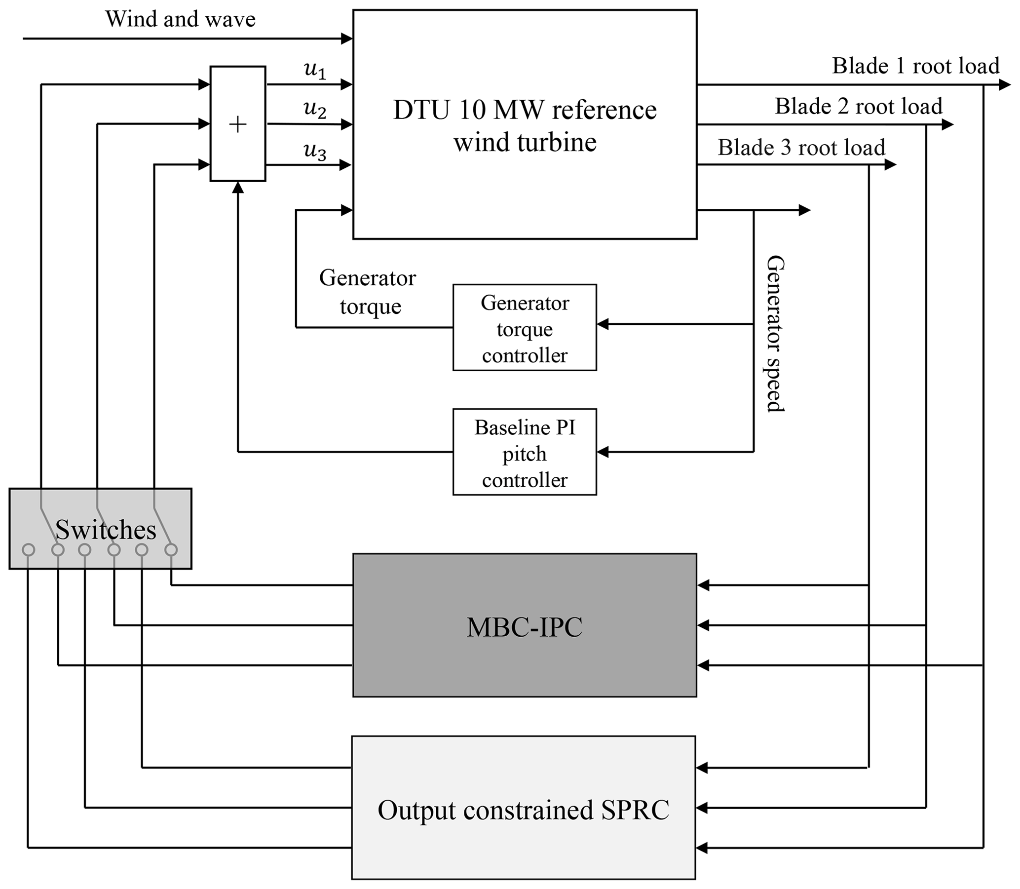
Figure 1Block diagram of the wind turbine model and of the control loop. The aero-hydro-structural dynamic part is simulated in the FAST model, while the turbine control part, including a baseline CPC (Jonkman and Buhl, 2005), an MBC-IPC (Mulders et al., 2019) and the proposed cSPRC, is implemented in Simulink. These two IPC controllers can be selectively enabled in order to compare their performances against each other and against the baseline controller alone. The baseline PI pitch controller and generator torque controller are always activated to guarantee the basic performance of the wind power generation.
The baseline control is based on a linear time-invariant (LTI) dynamical system (Bak et al., 2013). The MBC-based IPC is implemented following the work of Mulders et al. (2019). On the other hand, the proposed cSPRC approach will be introduced in Sect. 3 to show the capability of output constraints and its application to the load control of wake overlapping and turbulent sheared wind flow scenarios.
This section outlines the theoretical framework of the cSPRC approach for wind turbine load control. First of all, a discrete-time LTI system along with an output predictor is established to approximate the wind turbine dynamics. All the parameters of the linear representation are then identified via an online recursive subspace identification. Based on this, the predictive repetitive control law subjected to the different kinds of constraints is then synthesized by solving an MPC optimal problem in receding horizon. Especially, the output constraints of the controller, because of the presence of uncertainty in the identified model, are implemented as soft constraints by introducing slack variables in the MPC. Furthermore, only the control inputs in the MPC are penalized, which ensures that the controller will be only activated for load mitigation when the blade loads violate the output constraints. The overall structure of the cSPRC approach has been illustrated in Fig. 2.
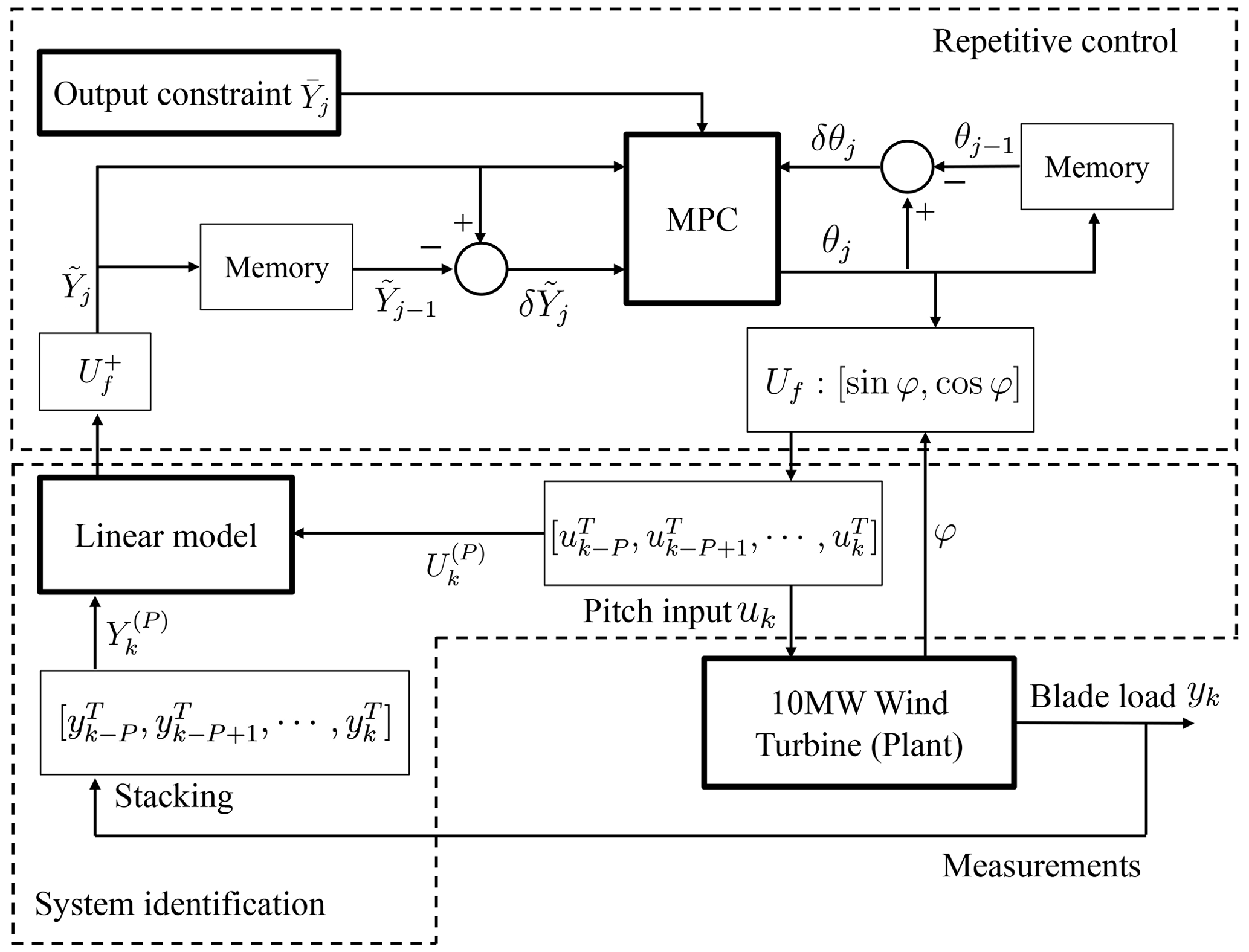
Figure 2Implementation of cSPRC, which includes online system identification and repetitive control. MPC optimization is used to incorporate the output constraints in repetitive control formulation. Uf represents the basis function, while the symbol denotes the Moore–Penrose pseudo-inverse of the basis function. In addition, uk, yk are the input and output vectors at discrete time index k. θj, , and denote the transformed control input, the transformed control output and the output constraints at rotation j. P and φ correspond to the period of the disturbance and rotor azimuth.
3.1 Online recursive subspace identification
In the cSPRC framework, the wind turbine dynamics are represented by a LTI system affected by unknown periodic disturbances (Houtzager et al., 2013) as
where xk∈ℝn, uk∈ℝr and yk∈ℝl denote the state, control input and output vectors. In the wind turbine model, . uk and yk represent the blades pitch angles and the blade loads, i.e., out-of-plane bending moment (MOoP), respectively, at discrete time index k. Moreover, dk∈ℝm is the periodic disturbance component of the loads at the blade root, while ek∈ℝl is the zero-mean white innovation process or the aperiodic component of the blade loads. Other matrices , , , , and denote the state transition, input, output, observer, periodic noise input and periodic noise direct feed-through matrices, respectively.
The following equations can be derived by rewriting Eq. (1) in predictor form:
in which and . Let us define a periodic difference operator , where P is the period of the disturbance, equalling to the blade rotation period. Then the effect of the periodic blade loads dk on the input–output system can be eliminated as the following equation holds
Similarly, δu, δx and δe can be defined as well. Applying the δ notation to Eq. (2), this equation can be rewritten as follows, where the periodic blade load term disappears.
Then, a stacked vector for a past time window with the length of p is given by
Similarly, the vector is defined. Next, the future state vector δxk+p is introduced based on and as
in which and are
It is worth noting that p needs to be selected large enough, in order to guarantee (Chiuso, 2007). With this in mind, δxk+p can be simplified as
By substituting this equation into Eq. (3), the approximation of δyk+p is derived as
From Eq. (7), it can be seen that the matrix of coefficients , which is the so-called Markov matrix Ξ, includes all the necessary information on the wind turbine dynamics. It is determined by the input vector u(r) and output vector y(l). In essence, the subspace identification aims to find an online solution of the following recursive least-squares (RLS) optimization problem (van der Veen et al., 2013):
In Eq. (8), λ is a forgetting factor () to alleviate the effect of past data and adapt to the updated system dynamics online. In this paper, a value close to 1, i.e., λ=0.9999, is chosen to guarantee the robustness of the optimization process. According to the definition of Ξ in Eq. (7), at time index k includes estimates of the following matrices:
To obtain a unique solution to this RLS optimization problem, persistently exciting signals are superimposed on top of the control input. Subsequently, this RLS optimization (Eq. 8) is implemented with a QR algorithm (Sayed and Kailath, 1998) in an online recursive manner to obtain . Thanks to the online recursive system identification, will be adapted to different operating conditions by learning the wind turbine dynamics online. Then it is used in an MPC framework to formulate a repetitive control law subjected to the output constraints. The implementation of the repetitive control problem formulation in MPC, namely the receding horizon repetitive control, will be elaborated in the next subsection.
3.2 Output-constrained repetitive control
Based on the LTI system obtained in subspace identification step, the constrained repetitive control law is formulated over P. Considering that P≥p and usually P is much larger than p, the output equation can be lifted over P as
is the Toeplitz matrix, which is defined as
By replacing B with L, can be derived as well. In addition, the extended observability matrix is given by
Substituting Eq. (10) with Eq. (6), it yields
In Eq. (13), it is worth noting that the first columns of and are 0. Moreover, the future output is actually predicted by previous and and future input . It can be rewritten as
with the definitions of Γ(P) and as follows:
In order to take into account output in the optimization problem, Eq. (14) is then expanded as
An MPC optimization is subsequently implemented to synthesize the repetitive control law, where the output constraints are incorporated into the control problem formulation. With this in mind, Eq. (15) is reformulated into a state space representation where the synthesized final input can be penalized as well, which is
The state transition and input matrices are updated at each discrete time instance k. Next, a basis function projection (van Wingerden et al., 2011) is employed to limit the spectral content of the pitch control input within the frequency range of interest. More importantly, it will reduce the dimension of Eq. (16) that must be solved in the MPC framework, thus leading to a reduced computational cost. In this paper, the 1P frequency load on the rotor blades, which is mainly induced by the wind shear, wind turbulence, changes in the inflow wind speed and tower shadow, is taken into account. The transformation matrix of the basis function projection can thus be defined as
where is the so-called basis function. The mathematical symbol ⊗ represents the Kronecker product.
Remark 1. Tne issue need to be addressed in the cSPRC algorithm is the potential variation of the rotor speed due to the varying inflow wind speed. This will result in a phase shift between control input and output.
To solve this problem, the rotor azimuth ψ, equal to at time instant k, is utilized to reformulate Uf to take into account the rotor speed variations. In this context, Eq. (17) can be rewritten into the following form:
Based on the basis function, the control inputs at specific frequencies are synthesized by taking a linear combination of the sinusoids of the transformation matrix as
where represents the rotation count. , which determines the amplitudes and phase of the sinusoids, is computed based on Eq. (16) at each P. To excite the wind turbine system dynamics, the persistently exciting signals are superimposed on top of the transformed control input θj. The control inputs now are given by
where the vector is the filtered pseudo-random binary noise. Thanks to the transformation matrix ϕ, the energy of the persistently exciting control input can be restricted on the specified 1P frequency as well. This will alleviate the negative effects of the excitation on the nominal wind turbine dynamics. Furthermore, η is generated in an uncorrelated way with different random seeds for each component of the vector θ to guarantee the successful excitation. On the other hand, the output can be transformed onto the subspace that defined by the basis function, as
in which the symbol + denotes the Moore–Penrose pseudo-inverse. Based on the basis function projection, Eq. (16) is reduced into a lower-dimensional form:
Compared to Eq. (16), the dimension of the projected matrix, i.e., , is much lower than the original matrix . Considering P≫b, the order of the state-space representation as well as the following MPC optimization problem can be substantially reduced. On the other hand, such a basis function transformation guarantees that the input is a smooth signal at the specific frequencies. Then the following output constraints, considering the transformation in Eq. (21), are imposed on Eq. (22) for all j≥0 as
where are the constraints of the future output , corresponding to the designed safety bounds of the blade loads. If the blade loads do not exceed the desired bounds, then the safety of the rotor is guaranteed. The value of the bounds can be determined by the wind farm operator or according to the safety factors of the loads in the design regulation such as IEC 61400-1 (IEC, 2005), or other safety limitations and environmental conditions. For instance, the safety bounds for the blade loads can be define by
where ξ is the safety factor and Yc denotes the characteristic value for the loads, e.g., standard deviation of the loads. For the normal operating condition of the wind turbine, ξ can be selected as 1.35 (IEC, 2005). is usually dependent on the safety loads of the wind turbine; thus such constraints vary for different operating conditions. Furthermore, cSPRC aims at the reduction of MOoP variation; the steady-state values of MOoP are not taken into account in such an IPC approach. Since the future output corresponds to the first element in Eq. (22), such output constraints can be converted into input constraints. Substituting Eq. (22) into Eq. (23), the output constraints are reformulated as
in which C is a diagonal matrix in the following form:
Following the philosophy of the MPC algorithm, the control objectives are introduced in the following cost function as
with the MPC optimization problem as
subjected to
where Q and R denote the positive-definite weighting matrices, while Np and Nu are the prediction and control horizons, respectively. Since the cSPRC framework is designed to be only active when the blade loads violate the output constraints, Q is set to an all-zeros weighting matrix. This will make the only penalization term in the cost function. To guarantee a quick response to the output violations and also perform a good trade-off between the control stability and the convergence rate, a value close to 1 is selected for each element of R. is a sequence of a series of future control actions. They are computed by the MPC optimization over the prediction horizon at each rotation count j. This will optimize the future behavior of the wind turbine while respecting the output constraints in Eq. (23).
As usual in MPC implementations, only the first element in the vector of the optimal input sequence U is used while the remaining elements are discarded. The entire optimization procedure is repeated at the end of each rotation of the rotor. At the next rotation period j+1, the updated state is used as an initial condition, while the cost function time limits in Eq. (27) roll ahead one step according to the receding horizon principle (Qin and Badgwell, 2003).
Equation (28) can be solved as a standard quadratic programming (QP) problem. With the all-zeros weighting matrix Q in mind, the control objectives in Eq. (27) can be converted to the following form:
where corresponds to the vector of state predictions. ℛ is the weight matrix, which is
By introducing the following prediction matrices,
Equation (22) is rewritten as
Combining Eq. (33) with Eq. (30), the MPC optimization can be solved in a simplified QP problem with only penalization of the control input,
subjected to
where H=2ℛ. In addition, G and W are defined according to Eq. (29), in a similar manner as in Bemporad et al. (2002).
Remark 2. The output constraints should be introduced in the control system cautiously as it could cause instability of the predictive control system due to the non-linearity appearing in the control law and the model–plant mismatch (Wang, 2009). To avoid this issue, we will introduce an output constraints relaxation, such that it allows the output constraints to be violated, but incurring a heavy penalty cost. This is achieved by introducing the so-called slack variables ρ.
As a result, the output constraints will be relaxed once the slack variables tend to large values during the control problem formulation. The implementation of the slack variables in the objective function is
subjected to
where F is the weighting matrix for the slack variables. With the penalization of the slack variables, the output constraints are softened to increase the control stability.
The implementation of the constrained repetitive control is schematically presented in Fig. 2. As the Markov matrix is derived from the online recursive subspace identification Eq. (8), the MPC optimization is implemented in Eqs. (36)–(37). When the blade loads of the wind turbine violate the output constraints, this cSPRC algorithm will formulate the repetitive control law for load mitigation, as shown in Eq. (19). Otherwise, only the baseline controller is active to maintain the basic control performance, thus leading to the reduced actuator activities.
In this section, the effectiveness of cSPRC in dealing with the output constraints is demonstrated on the wind turbine model via a series of case studies. For the sake of comparison, the load reduction and the pitch ADC of the proposed cSPRC approach, baseline CPC and MBC-based IPC are computed for investigation.
4.1 Model configuration
The wind turbine model, which has been introduced in Sect. 2, is simulated by the FAST v8.16 simulation package (Jonkman and Buhl, 2005). It is coupled with Simulink, where the wind turbine torque and pitch control systems are implemented. Two typical scenarios are considered in this paper:
-
wake–rotor overlap condition, in which the wind turbine is impinged by a steady-state wind farm wake shed from an upstream turbine, which shows partial and full wake–rotor overlap;
-
turbulent sheared wind condition, in which the wind turbine is subjected to turbulent sheared wind flows.
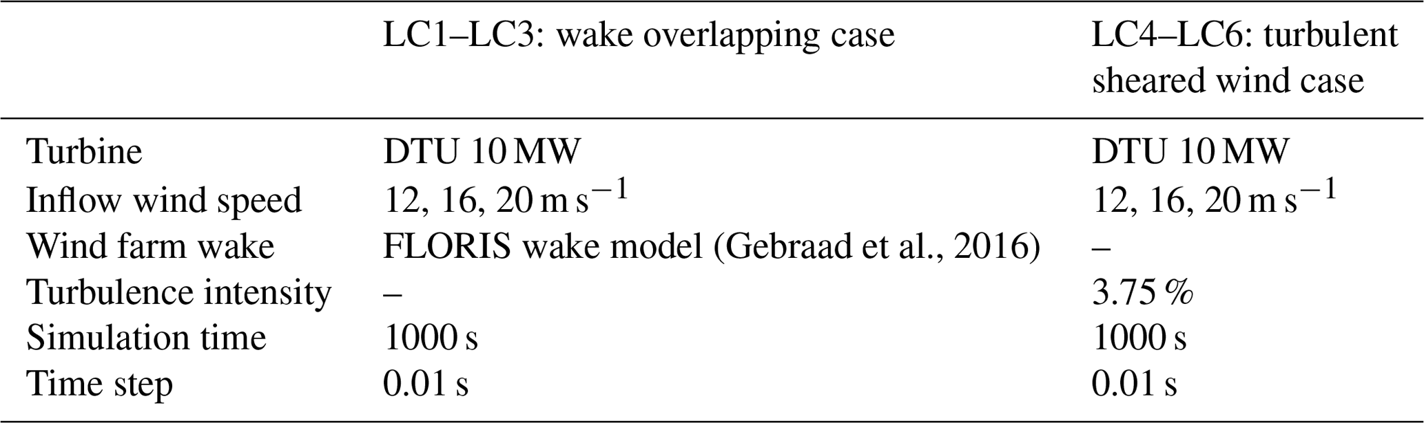
The steady-state wind farm wake is simulated by the widely used FLORIS model (Gebraad et al., 2016). In the parameterization of the FLORIS wake model, the turbulence intensity (TI) of 6.0 % is utilized to define the wake recovery, while the center-to-center distance between the wake center and the downstream turbine rotor center – 5 diameters (5 D) of the rotor – is specified, which implies that the simulated wind turbine in the FAST tool is situated 5 D behind the upstream turbine. Other effects such as wake meandering and turbulence logarithmic wind profile are not included in this scenario. For the turbulent sheared wind condition, a series of turbulent varying wind fields are simulated via the TurbSim model1, where the TI is set to be 3.75 %. The inflow wind speeds are specified as 12, 16 and 20 m s−1. The wind profile is based on the IEC power-law model (IEC, 2009). These two scenarios result in a total of six load cases (LCs) in the case study. All of them are summarized in Table 2.
(Gebraad et al., 2016)Table 2Model configuration and environmental conditions in FAST–Simulink simulations for all LCs.
Then, the time series of the wind fields, which are based on the simulation results of the FLORIS and TurbSim, are fed into the FAST/Simulink model as the input of the wind turbine simulation. In all the LCs, the simulation lasts 1000 s at a fixed discrete time step of 0.01 s. For comparison, three different control strategies, i.e., baseline CPC, MBC-based IPC and cSPRC, are simulated respectively in each LC. This finally leads to a total of simulation runs.
4.2 Results and discussions
4.2.1 Scenario I: wake–rotor overlap
First of all, the wake–rotor interaction is presented in Fig. 3. The wind farm wake shed from the upstream turbine propagates from left to right sectors of the rotor, thus leading to the wake–rotor overlap on the downstream turbine. As visible, the wind farm wake generated by the FLORIS model shows an in-wake velocity deficit, which is indicated by the blue regions in Fig. 3. It will cause significant asymmetric loading on the rotor blades when the downstream turbine experiences the partial wake overlap (such as in 300–500 and 700–800 s). The load control for such partial overlap-induced asymmetric loads is demonstrated through a series of comparison studies. Figure 4 shows the time series of MOoP and corresponding pitch angles on one blade. As IPC strategies only aim at the reduction of MOoP variations, the steady values of MOoP are removed by a high-pass filter.
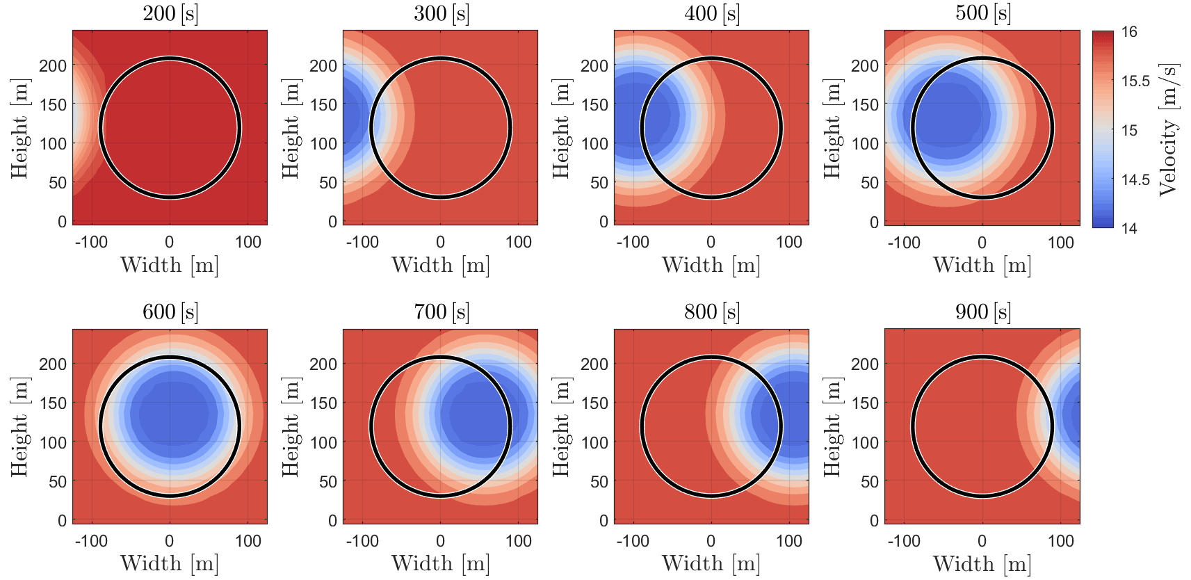
Figure 3Vertical slice of the wind field at the downstream turbine in LC2 (16 m s−1 wind speed), where the rotor is impinged and overlapped by a wake. Red regions imply high wind velocity, which is undisturbed by the upstream turbine, while the blue regions reveal a velocity deficit due to the upstream turbine.
It can be seen that MOoP is significantly increased when the wake impinges on the left sector of the rotor at around 350 s, leading to the partial wake–rotor overlap. Due to the increase of MOoP, the proposed cSPRC actively generates the IPC action to reduce the asymmetric blade loads into the safety bounds and avoid violating the output constraints. Thus, significant load reduction can be observed for 350–550 s. As time goes by, the rotor is fully overlapped with the wake, which results in the reduced MOoP. Since the blade loads do not violate the output constraints at 600 s, only the baseline CPC is active to maintain the basic wind turbine performance, which leads to reduced actuator activities. Again, the wake impinged the right sector of the rotor at around 640 s. The increased blade loads enables cSPRC to provide the IPC action for load mitigation. In comparison, MBC-based IPC, which is a conventional IPC approach, actually shows maximum potential of load reduction. However, significant actuator activities are demanded by MPC-based IPC. For example, the corresponding pitch rates are presented in Fig. 6. MBC-based IPC shows highest pitch rates, which lead to large cyclic fatigue loads on the actuators. The developed cSPRC, however, is only active in load mitigation when the blade loads violate the output constraints, thus significantly reducing the actuator activities.
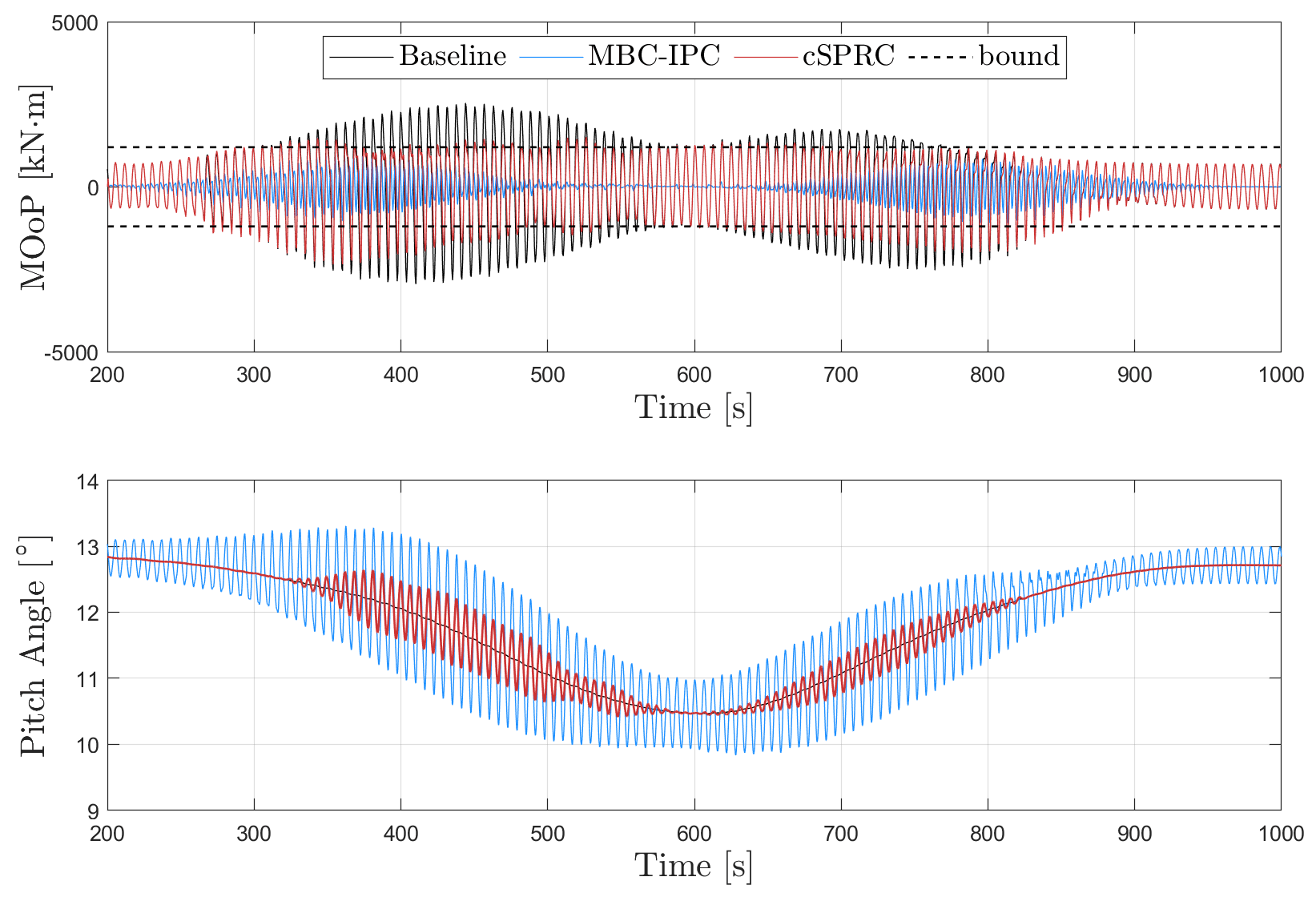
Figure 4MOoP on the blade root in LC2 (16 m s−1 wind speed) and its corresponding pitch angles, where the output constraints in the developed cSPRC are enabled at 200 s. The steady-state values of MOoP have been removed. The designed safety bounds corresponding to the output constraints are 1200 kN m1.
The cost function of the MPC optimization in cSPRC is illustrated in Fig. 5. It essentially implies the desired actuator activities for load mitigation in cSPRC. The value of the cost function increases when the wind turbine experiences the partial wake overlap. In the case where the blade loads satisfy the output constraints, the value of the cost function is reduced to zero. Note that as the slack variables are included in cSPRC, the output constraints are not always respected. Some violations can be still observed in 300–400 s in Fig. 4. This will avoid the instability of the closed-loop control system due to the non-linearity occurring in the control law and the model–plant mismatch.
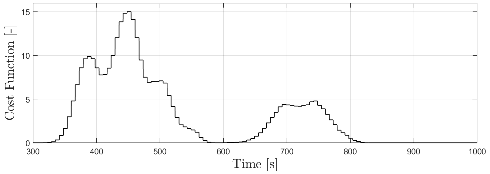
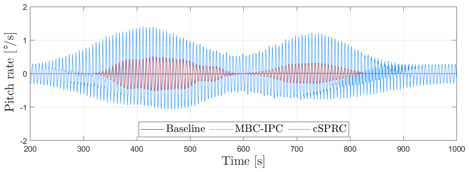
Figure 6Pitch rate of the blade in LC2 (16 m s−1 wind speed), where the output constraints in the developed cSPRC are enabled at 200 s.
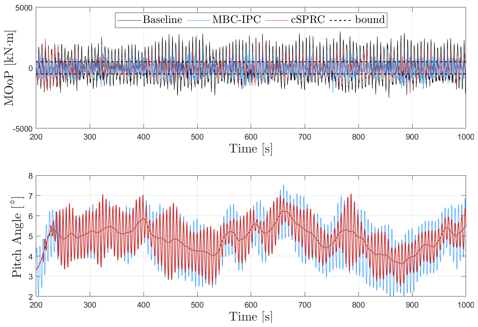
Figure 7MOoP on the blade root and its corresponding pitch angles in LC4 (12 m s−1 wind speed, TI 3.75 % case), where the output constraints in the developed cSPRC are enabled at 200 s. The steady-state values of MOoP have been removed. The designed bound corresponding to the output constraints is 500 kN m1.
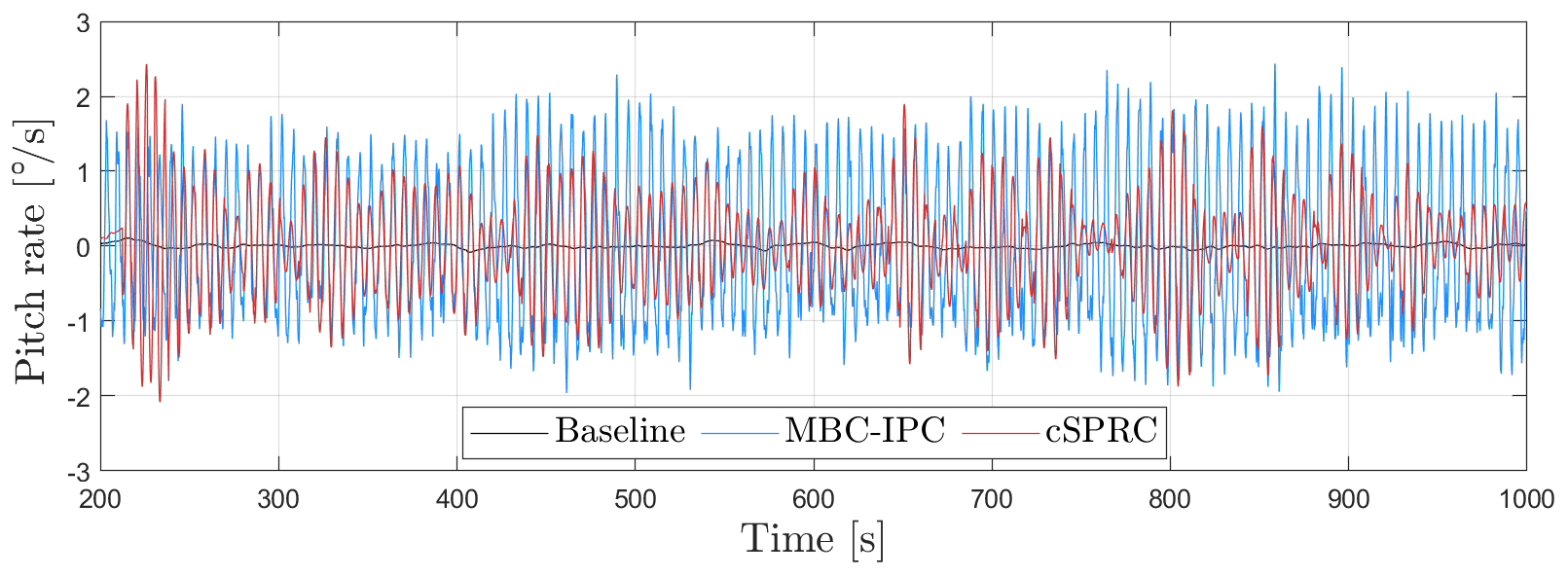
Figure 8Pitch rate of the blade in LC4 (12 m s−1 wind speed, TI 3.75 % case), where the output constraints in the developed cSPRC are enabled at 200 s.
4.2.2 Scenario II: turbulent sheared wind condition
Another scenario considered in the case study is the turbulent sheared wind condition. Figures 7 and 8 show the time series of MOoP, corresponding pitch angles and pitch rate in LC5. Similarly, the cSPRC formulates the IPC action for load reduction when the turbulence-induced loads violate the output constraints. By using a tight safety bound of 500 Kn m1, we can see that significant load reduction is achieved by cSPRC while the output constraints are generally respected. Since the slack variables are used to relax the output constraints, some constraints violations are observed from Fig. 7. On the other hand, MBC-based IPC shows maximum load reduction in the turbulent sheared wind case; however, it will induce more actuator activities, as indicated by the pitch rate in Fig. 8. This approach, considering the blade loads are minimized into the safety bounds, is an effective way to reduce the actuator activities and deal with the output constraints.
Other LCs show similar patterns and hence are omitted for brevity. Based on these comparisons, it can be concluded that the developed cSPRC approach shows good performance in handling the output constraints in both wake overlap and turbulent sheared wind scenarios. By designing safety bounds, it allows the wind farm operator to mitigate the loads into the safety bounds while reducing the actuator activities. However, the conventional approach, such as MBC-based IPC, usually mitigates the blade loads as much as possible. As a consequence, more actuator activities are demanded by the controller, which may lead to the reduced reliability of the control system due to the higher cyclic fatigue loads on the pitch actuators.
In order to quantify the load reduction and pitch activities of these control strategies, two indicators, namely the reduction of MOoP relative to baseline controller and the pitch ADC, are calculated for comparison. The latter one can be calculated according to the pitch rate (Bottasso et al., 2013), which is defined as
where denotes the pitch rate, while βmax is its maximum allowable value which is determined according to the specification of the wind turbine. t is the time. For the 10 MW wind turbine model, the value of βmax is
The pitch ADC, which actually implies the cyclic fatigue loads on the pitch actuators, is a widely used criterion to estimate the lifespan of pitch actuators. In addition, the ratio R between the reduction of MOoP and the pitch ADC is computed to comprehensively evaluate the control strategy. If R is larger, the control strategy is more effective in load reduction with the same amount of the pitch ADC and vice versa. All these results are summarized in Table 3. In general, the proposed cSPRC shows similar or higher values of R compared to MBC-based IPC, while its pitch ADC is significantly reduced in considered cases. For instance, cSPRC shows ∼1.7 % of the pitch ADC in LC2, whereas MBC-based IPC shows ∼5.5 % of the pitch ADC in this case. Averaging over all the cases, the proposed control strategy shows the pitch ADC of ∼4 %, thus leading to a higher R of 8.5 %. Considering the significant reduction of the pitch ADC and higher R, it indicates that cSPRC is effective at reducing the actuator activities and maintains the same level of load mitigation. By incorporating the output constraints, this approach is able to minimize the loads into the designed safety bounds with low actuator activities.
Table 3Comparison of the indicators (reduction of MOoP, pitch ADC and ratio R) in cSPRC and MBC-based IPC*.
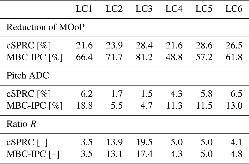
* The results are calculated based on the data from 300–1000 s in wake overlap scenarios (LC1–LC3) and 750–1000 s in turbulent sheared wind conditions (LC4–LC6). The reduction of MOoP represents the percentage of changes with respect to the baseline CPC case.
In comparison, MBC-based IPC aims at attaining the maximum load reduction. However, it causes excessive pitch ADC and thus leads to a lower R. Since the output constraints are taken into account in cSPRC, the proposed framework is able to only mitigate the blade loads violating the designed safety bounds. In this way, the pitch ADC is significantly alleviated. Therefore, cSPRC might be a promising alternative to MBC-based IPC to perform a trade-off between the load reduction and the pitch ADC in all considered cases.
In this paper, a fully data-driven individual pitch control (IPC) approach, which is called constrained subspace predictive repetitive control (cSPRC), is developed to explicitly consider the output constraints in the control problem formulation. This approach involves using online recursive subspace identification and model predictive control (MPC) to formulate the repetitive control law subjected to the output constraints. The cSPRC approach aims to produce the IPC action for load mitigation when the blade loads violate the output constraints while the baseline pitch controller is always active to maintain the basic wind turbine performance.
The effectiveness of the developed cSPRC in dealing with the output constraints is illustrated on a DTU 10 MW reference wind turbine model, where the wake–rotor overlap and turbulent sheared wind conditions are considered respectively. It proves that the cSPRC approach is effective at limiting the blade loads into the designed safety bounds, showing effective load mitigation with low pitch activities: the blade loads are reduced by ∼25 %, while pitch actuator duty cycle (ADC) is only ∼4 %, thus leading to a ratio R of ∼9 %. Moreover, it is interesting to note that cSPRC only produces the IPC action for load mitigation when the blade loads violate the output constraints. This, to some extent, reduces the actuator activities. Furthermore, cSPRC can be readily extended to the multifrequency IPC by expanding the basis function.
In this paper, the cSPRC approach is compared to MBC-based IPC. The case study shows that MBC-based IPC attains maximum load reduction, however at the expense of increased pitch ADC. In comparison, the proposed cSPRC framework, by dealing with the output constraints, is capable of achieving more economical load reduction and shows much lower pitch ADC. More importantly, this approach enables the wind farm operator to design conservative bounds for the load control. Since cSPRC only formulates the IPC actions to prevent violating constraints, it will significantly alleviate the pitch ADC and extend the lifespan of the pitch control system. Based on the comparison study, it is worth noting that both cSPRC- and MBC-based IPC show similar but substantially different scopes. MBC-based IPC targets a maximum load reduction at the expense of high-pitch ADC. cSPRC might be a complementary alternative to MBC-based IPC to achieve a trade-off between the load reduction and the pitch ADC. Future work will include, but are not limited to, considering other wake effects such as wake meandering and dynamic propagation of the wake, executing scaled wind tunnel experiments, and full-scale tests on a real wind turbine or wind farm.
The data analyzed in this paper are confidential and cannot be shared publicly.
This video https://doi.org/10.5446/50771 (Liu, 2020) demonstrates a case study where the wind turbine is impinged and overlapped by the wake shed from the upstream turbine. Three control strategies, i.e., baseline collective pitch control, Coleman transformation based individual pitch control, output-constrained subspace predictive repetitive control, are used for comparison.
YL and JWvW conceived the idea of this research. YL performed the data processing, formal analysis, visualization and wrote the paper. RF and JWvW provided essential suggestions and reviewed the paper.
The contact author has declared that neither they nor their co-authors have any competing interests.
Publisher's note: Copernicus Publications remains neutral with regard to jurisdictional claims in published maps and institutional affiliations.
The authors are grateful for support from the European Union via the Marie Skłodowska-Curie Actions (Grant EDOWE, no. 835901) and the Horizon 2020 Research and Innovation Programme (Project HIPERWIND, no. 101006689). The authors also would like to thank the reviewers and the editors for their thoughtful comments and contribution to this research.
This research has been supported by the H2020 Marie Skłodowska-Curie Actions (Grant EDOWE, no. 835901) and the Research and Innovation Programme (Project HIPERWIND, no. 101006689).
This paper was edited by Alessandro Croce and reviewed by Torben Knudsen and one anonymous referee.
Bak, C., Zahle, F., Bitsche, R., Kim, T., Yde, A., Henriksen, L. C., and Natarajan, A.: The DTU 10-MW Reference Wind Turbine, Report, DTU Wind Energy, https://backend.orbit.dtu.dk/ws/portalfiles/portal/55645274/The_DTU_10MW_Reference_Turbine_Christian_Bak.pdf (last access: 3 March, 2022), 2013. a, b, c
Barthelmie, R. J., Frandsen, S. T., Nielsen, M. N., Pryor, S. C., Rethore, P.-E., and Jørgensen, H. E.: Modelling and measurements of power losses and turbulence intensity in wind turbine wakes at Middelgrunden offshore wind farm, Wind Energy, 10, 517–528, https://doi.org/10.1002/we.238, 2007. a
Bemporad, A., Morari, M., Dua, V., and Pistikopoulos, E. N.: The explicit linear quadratic regulator for constrained systems, Automatica, 38, 3–20, 2002. a
Bir, G.: Multi-Blade Coordinate Transformation and its Application to Wind Turbine Analysis, in: 46th AIAA Aerospace Sciences Meeting and Exhibit, 7–10 January 2008, Reno, Nevada, 2008. a, b
Bossanyi, E. A.: Individual Blade Pitch Control for Load Reduction, Wind Energy, 6, 119–128, 2003. a, b
Bossanyi, E. A.: Further load reductions with individual pitch control, Wind Energy, 8, 481–485, 2005. a
Bottasso, C., Campagnolo, F., Croce, A., and Tibaldi, C.: Optimization-based study of bend–twist coupled rotor blades for passive and integrated passive/active load alleviation, Wind Energy, 16, 1149–1166, 2013. a
Boukhezzar, B., Lupu, L., Siguerdidjane, H., and Hand, M.: Multivariable control strategy for variable speed, variable pitch wind turbines, Renew. Energy, 32, 1273–1287, 2007. a
Chiuso, A.: The role of vector autoregressive modeling in predictor-based subspace identification, Automatica, 43, 1034–1048, 2007. a
Fleming, P., Gebraad, P. M., Lee, S., van Wingerden, J. W., Johnson, K., Churchfield, M., Michalakes, J., Spalart, P., and Moriarty, P.: Simulation comparison of wake mitigation control strategies for a two-turbine case, Wind Energy, 18, 2135–2143, 2015. a
Frederik, J., Kröger, L., Gülker, G., and van Wingerden, J. W.: Data-driven repetitive control: Wind tunnel experiments under turbulent conditions, Control Eng. Pract., 80, 105–115, 2018. a
Frederik, J. A., Doekemeijer, B. M., Mulders, S. P., and van Wingerden, J.-W.: The helix approach: Using dynamic individual pitch control to enhance wake mixing in wind farms, Wind Energy, 23, 1739–1751, https://doi.org/10.1002/we.2513, 2020a. a
Frederik, J. A., Weber, R., Cacciola, S., Campagnolo, F., Croce, A., Bottasso, C., and van Wingerden, J.-W.: Periodic dynamic induction control of wind farms: proving the potential in simulations and wind tunnel experiments, Wind Energ. Sci., 5, 245–257, https://doi.org/10.5194/wes-5-245-2020, 2020b. a
Gebraad, P. M. O., Churchfield, M. J., and Fleming, P. A.: Incorporating Atmospheric Stability Effects into the FLORIS Engineering Model of Wakes in Wind Farms, J. Phys.: Conf. Ser., 753, 052004, https://doi.org/10.1088/1742-6596/753/5/052004, 2016. a, b, c
Global Wind Energy Council: Global Wind Report 2021, Report, Global wind energy council, https://gwec.net/global-wind-report-2021/ (last access: 3 March 2022), 2021. a
Houtzager, I., van Wingerden, J. W., and Verhaegen, M.: Wind turbine load reduction by rejecting the periodic load disturbances, Wind Energy, 16, 235–256, 2013. a
IEC: IEC 61400-1 Wind Turbines – Part 1: Design Requirements, Multiple, Distributed through American National Standards Institute (ANSI), ISBN 978-2832262535, 2005. a, b, c
IEC: IEC 61400-3 Wind Turbines – Part 3: Design Requirements for Offshore Wind Turbines, Multiple, Distributed through American National Standards Institute (ANSI), ISBN 9782889105144, 2009. a
Jonkman, J. M. and Buhl, M. L.: FAST User's Guide, Nat. Renew. Energy Lab., Golden, CO, USA, Rep. NREL/EL-500-38230 (previously NREL/EL-500-29798), 2005. a, b, c, d, e
Knudsen, T., Bak, T., and Svenstrup, M.: Survey of wind farm control–power and fatigue optimization, Wind Energy, 18, 1333–1351, https://doi.org/10.1002/we.1760, 2015. a
Larsen, G. C., Madsen, H. A., Thomsen, K., and Larsen, T. J.: Wake meandering: a pragmatic approach, Wind Energy, 11, 377–395, 2008. a
Lemmer, F., Amann, F., Raach, S., and Schlipf, D.: Definition of the SWE-TripleSpar Floating Platform for the DTU 10 MW Reference Wind Turbine, Report, SWE – Stuttgart Wind Energy, https://darus.uni-stuttgart.de/ (last access: 3 March 2022), 2016. a, b
Liu, Y.: Output Constrained, Subspace Predictive Repetitive Control Approach for Wind Turbine Load Reduction, TIB AV-PORTAL [video supplement], https://doi.org/10.5446/50771, 2020. a
Liu, Y., Frederik, J., Fontanella, A., Ferrari, R. M., and van Wingerden, J. W.: Adaptive fault accommodation of pitch actuator stuck type of fault in floating offshore wind turbines: a subspace predictive repetitive control approach, in: 2020 American Control Conference (ACC), 4077–4082, https://doi.org/10.23919/ACC45564.2020.9147695, 2020a. a
Liu, Y., Wu, P., Ferrari, R. M., and van Wingerden, J. W.: Fast Adaptive Fault Accommodation in Floating Offshore Wind Turbines via Model-Based Fault Diagnosis and Subspace Predictive Repetitive Control, in: 21st IFAC World Congress, IFAC-PapersOnLine, 53, 12650–12655, 2020b. a
Liu, Y., Ferrari, R. M., and van Wingerden, J. W.: Periodic Load Rejection for Floating Offshore Wind Turbines via Constrained Subspace Predictive Repetitive Control, in: 2021 American Control Conference (ACC), 539–544, https://doi.org/10.23919/ACC50511.2021.9483333, 2021a. a
Liu, Y., Frederik, J., Ferrari, R. M., Wu, P., Li, S., and van Wingerden, J. W.: Fault-tolerant individual pitch control of floating offshore wind turbines via subspace predictive repetitive control, Wind Energy, 24, 1045–1065, 2021b. a
Liu, Y., Pamososuryo, A. K., Ferrari, R., Hovgaard, T. G., and van Wingerden, J. W.: Blade Effective Wind Speed Estimation: A Subspace Predictive Repetitive Estimator Approach, in: 2021 European Control Conference (ECC), 1205–1210, https://doi.org/10.23919/ECC54610.2021.9654981, 2021d. a
Liu, Y., Pamososuryo, A. K., Ferrari, R. M. G., and van Wingerden, J. W.: The Immersion and Invariance Wind Speed Estimator Revisited and New Results, IEEE Control Syst. Lett., 6, 361–366, https://doi.org/10.1109/LCSYS.2021.3076040, 2022a. a
Liu, Y., Pamososuryo, A. K., Mulders, S. P., Ferrari, R. M. G., and van Wingerden, J. W.: The Proportional Integral Notch and Coleman Blade Effective Wind Speed Estimators and Their Similarities, IEEE Control Syst. Lett., 6, 2198–2203, https://doi.org/10.1109/LCSYS.2021.3140171, 2022b. a
Mulders, S. P., Pamososuryo, A. K., Disario, G. E., and van Wingerden, J. W.: Analysis and optimal individual pitch control decoupling by inclusion of an azimuth offset in the multiblade coordinate transformation, Wind Energy, 22, 341–359, 2019. a, b, c
Navalkar, S., van Wingerden, J. W., van Solingen, E., Oomen, T., Pasterkamp, E., and van Kuik, G.: Subspace predictive repetitive control to mitigate periodic loads on large scale wind turbines, Mechatronics, 24, 916–925, 2014. a
Navalkar, S. T., van Solingen, E., and van Wingerden, J. W.: Wind Tunnel Testing of Subspace Predictive Repetitive Control for Variable Pitch Wind Turbines, IEEE T. Control Syst. Technol., 23, 2101–2116, 2015. a
Njiri, J. G. and Söffker, D.: State-of-the-art in wind turbine control: Trends and challenges, Renew. Sustain. Energ. Rev., 60, 377–393, 2016. a
Petrović, V., Jelavić, M., and Baotić, M.: MPC framework for constrained wind turbine individual pitch control, Wind Energy, 24, 54–68, https://doi.org/10.1002/we.2558, 2021. a
Qin, S. and Badgwell, T. A.: A survey of industrial model predictive control technology, Control Eng. Pract., 11, 733–764, 2003. a, b
Sayed, H. and Kailath, T.: Recursive Least-Squares Adaptive Filters, Press LLC, ISBN 9781315219837, 1998. a
Selvam, K., Kanev, S., van Wingerden, J. W., van Engelen, T., and Verhaegen, M.: Feedback–feedforward individual pitch control for wind turbine load reduction, Int. J. Robust Nonlin. Control, 19, 72–91, 2009. a
Ungurán, R., Petrović, V., Boersma, S., van Wingerden, J. W., Pao, L. Y., and Kühn, M.: Feedback-feedforward individual pitch control design for wind turbines with uncertain measurements, in: 2019 American Control Conference (ACC), 4151–4158, https://doi.org/10.23919/ACC.2019.8814757, 2019. a
Vali, M., van Wingerden, J. W., and Kühn, M.: Optimal multivariable individual pitch control for load reduction of large wind turbines, in: 2016 American Control Conference (ACC), 3163–3169, https://doi.org/10.1109/ACC.2016.7525404, 2016. a
van der Veen, G., van Wingerden, J. W., Bergamasco, M., Lovera, M., and Verhaegen, M.: Closed-loop subspace identification methods: an overview, IET Control Theor. Appl., 7, 1339–1358(19), 2013. a, b
van Kuik, G. A. M., Peinke, J., Nijssen, R., Lekou, D., Mann, J., Sørensen, J. N., Ferreira, C., van Wingerden, J. W., Schlipf, D., Gebraad, P., Polinder, H., Abrahamsen, A., van Bussel, G. J. W., Sørensen, J. D., Tavner, P., Bottasso, C. L., Muskulus, M., Matha, D., Lindeboom, H. J., Degraer, S., Kramer, O., Lehnhoff, S., Sonnenschein, M., Sørensen, P. E., Künneke, R. W., Morthorst, P. E., and Skytte, K.: Long-term research challenges in wind energy – a research agenda by the European Academy of Wind Energy, Wind Energ. Sci., 1, 1–39, https://doi.org/10.5194/wes-1-1-2016, 2016. a
van Solingen, E., Navalkar, S., and van Wingerden, J. W.: Experimental wind tunnel testing of linear individual pitch control for two-bladed wind turbines, J. Phys.: Conf. Ser., 524, 012056, https://doi.org/10.1088/1742-6596/524/1/012056, 2014. a
van Wingerden, J. W., Hulskamp, A., Barlas, T., Houtzager, I., Bersee, H., van Kuik, G., and Verhaegen, M.: Two-Degree-of-Freedom Active Vibration Control of a Prototyped “Smart” Rotor, IEEE T. Control Syst. Technol., 19, 284–296, 2011. a, b
Wang, L.: Model predictive control system design and implementation using MATLAB®, Springer, https://doi.org/10.1007/978-1-84882-331-0, 2009. a, b, c
Willis, D., Niezrecki, C., Kuchma, D., Hines, E., Arwade, S., Barthelmie, R., DiPaola, M., Drane, P., Hansen, C., Inalpolat, M., Mack, J., Myers, A., and Rotea, M.: Wind energy research: State-of-the-art and future research directions, Renew. Energy, 125, 133–154, 2018. a
Yang, Z., Li, Y., and Seem, J. E.: Multi-model predictive control for wind turbine operation under meandering wake of upstream turbines, Control Eng. Pract., 45, 37–45, 2015. a
Yuan, Y., Chen, X., and Tang, J.: Multivariable robust blade pitch control design to reject periodic loads on wind turbines, Renew. Energy, 146, 329–341, 2020. a
TurbSim: a stochastic inflow turbulence tool to simulate realistic turbulent wind fields (https://www.nrel.gov/wind/nwtc/turbsim.html, last access: 3 March 2022).