the Creative Commons Attribution 4.0 License.
the Creative Commons Attribution 4.0 License.
 | 24 Oct 2023
OF2: coupling OpenFAST and OpenFOAM for high-fidelity aero-hydro-servo-elastic FOWT simulations
Guillén Campaña-Alonso
Raquel Martín-San-Román
Beatriz Méndez-López
Pablo Benito-Cia
José Azcona-Armendáriz
The numerical study of floating offshore wind turbines (FOWTs) requires accurate integrated simulations which consider the aerodynamic, hydrodynamic, servo and elastic responses of these systems. In addition, the floating system dynamics couplings need to be included to calculate the excitation over the ensemble accurately. In this paper, a new tool has been developed for coupling NREL's aero-servo-elastic tool OpenFAST with the computational fluid dynamics (CFD) toolbox OpenFOAM. OpenFAST is used to model the rotor aerodynamics along with the flexible response of the different components of the wind turbine and the controller at each time step considering the dynamic response of the platform. OpenFOAM is used to simulate the hydrodynamics and the platform's response considering the loads from the wind turbine. The whole simulation environment is called OF2 (OpenFAST and OpenFOAM). The OC4 DeepCWind semi-submersible FOWT together with NREL's 5 MW wind turbine has been simulated using OF2 under two load cases. The purpose of coupling these tools to simulate FOWT is to obtain high-fidelity results for design purposes, thereby reducing the computational time compared with the use of CFD simulations both for the rotor aerodynamics, which usually consider rigid blades, and for the platform's hydrodynamics. The OF2 approach also allows us to include the aero-servo-elastic couplings that exist on the wind turbine along with the hydrodynamic system resolved by CFD. High-complexity situations of floating offshore wind turbines, like storms, yaw drifts, weather vanes or mooring line breaks, which imply high displacements and rotations of the floating platform or relevant non-linear effects, can be resolved using OF2, overcoming the limitation of many state-of-the-art potential hydrodynamic codes that assume small displacements of the platform. In addition, all the necessary information for the FOWT calculation and design processes can be obtained simultaneously, such as the pressure distribution at the platform components and the loads at the tower base, fairleads tension, etc. Moreover, the effect of turbulent winds and/or elastic blades could be taken into account to resolve load cases from the design and certification standards.
- Article
(12538 KB) - Full-text XML
- BibTeX
- EndNote


Floating offshore wind turbine (FOWT) design and optimization are necessary to accomplish the requirements with regard to the increase in wind energy capacity installed worldwide. The reduction in the levelized cost of energy (LCOE) of offshore wind energy will be possible, among others, if the fidelity of the tools used to design an FOWT is improved without a great increase in computational time. In addition, the coupling of the wind turbine and platform dynamics is necessary to the ensemble optimizations required in wind turbine and platform co-design processes.
Most of the state-of-the-art hydrodynamic models used in engineering simulation tools, for the coupled analysis of FOWTs, are based on two different hydrodynamic models to resolve the hydrodynamic loads on the floating platform: Morison's equation (ME) and potential flow (PF) theory. The ME (see Morison et al., 1950) can be applied to slender bodies and provides the inertia and drag forces over these elements. The PF (see Newman, 1977; Faltinsen, 1993) is applicable to general geometries to solve the hydrodynamic problem, thereby obtaining the added mass, radiation damping, diffraction forces, etc., but does not include viscous effects. The viscous effects can be added to potential models through the drag term of Morison's equation or by adjusting the damping of the platform based on experimental data (see Azcona, 2016) or computational fluid dynamics (CFD) simulations. This potential solution can be obtained both in the frequency and in the time domains. Moreover, the forces and moments obtained by solving the potential problem in the frequency domain can be introduced into a time domain solver of the floating platform; see for example Jonkman (2007).
As mentioned before, the hydrodynamic response of floating platforms can also be modeled by performing high-fidelity CFD simulations. This method has nowadays become a part of the design process of FOWTs. These simulations support the design process and allow the tuning of the integrated numerical tools since the early stages of the process so that the effort put into wave tank testing is not lost once a mature platform design has been achieved. CFD simulations are used to provide quantitative information about the design process such as the damping coefficients needed in the engineering codes. In addition, flow phenomena such as wave run-up or pressures over the structure, or the heave plates, are provided to optimize the platform design and to understand its dynamics. Several publications can be found in which CFD is applied to simulate platform hydrodynamics. For instance, the OC6 Phase I collaborative work under the IEA Task 30 provided two publications; in the first one the platform's response to bi-chromatic waves was analyzed in Wang et al. (2021), placing special focus on the wave treatment, pressures over the structure and wave run-up analysis. In the second one, free decay simulations were performed to make a benchmark between different CFD codes, including a detailed comparison with experiments described in Wang et al. (2022a). Both publications demonstrated the potential of CFD use in platform design and characterization and pointed out the differences with regard to potential flow solver simulations. For example, it has been found that the potential flow solution used in Wang et al. (2021) significantly underpredicts the damping of surge motion. Another study from Wang et al. (2022b) delves deeper into the effect of irregular waves on the DeepCWind platform, lending credibility to and confidence in the use of high-fidelity CFD simulations in predicting the global performance of floating wind platforms and for tuning mid-fidelity engineering models.
On the other hand, rotor aerodynamics are simulated in the wind energy industry with different fidelity level tools ranging from blade element momentum theory (BEMT) (Bossanyi et al., 2001; Bladed, 2010), more complex free vortex filament methods (FVMs) (Kecskemety and McNamara, 2011; Marten et al., 2019), actuator line approaches (Quon et al., 2019; Branlard et al., 2014) and high-fidelity fully resolved CFD simulations. Typically, BEMT and FVM approaches are used for coupled aeroelastic simulations, while the different CFD approaches are used in purely aerodynamic simulations without considering the coupling with flexible degrees of freedom. Moreover, CFD is mainly used on the airfoil level or in specific cases in which extreme aerodynamic events need to be deeply analyzed. Recently, in the OC6 Phase III project numerous aerodynamic models with different fidelity levels have been compared, in purely aerodynamic conditions, with wind tunnel experimental data of a wind turbine placed over a moving structure capable of imposing displacements and rotations on the tower base of the wind turbine (Bergua et al., 2023). This study has shown that all analyzed aerodynamic models are capable of accurately predicting the aerodynamic loads under the forced pitch and surge motion studied in this OC6 Phase III project. However, it has been found that when considering the additional dynamics introduced by the controller, the aerodynamic cycles change.
Furthermore, the combined hydro-aero high-fidelity simulation of FOWTs under wind and wave conditions is a cutting-edge technology with few research works available in the literature (Otter et al., 2021; Micallef and Rezaeiha, 2021). In addition, in the few existing models it is very rare to see couplings with elastic models of the flexible elements of the wind turbine, such as the blades or the tower. And it is even more difficult to find models that include the coupling with the wind turbine control system. Ren et al. (2014) conducted a CFD analysis of the NREL 5 MW with a TLP structure under wind and wave conditions and simulated it with the commercial software Fluent. In that work only the surge motion was allowed. In their work, Liu et al. (2017) presented a coupled CFD simulation using OpenFOAM both in the rotor and in the floating platform. No information was provided about the computational time of their simulations. Tran and Kim (2016) carried out fully coupled aerodynamic–hydrodynamic simulations of the OC4 DeepCWind semi-submersible with a wind turbine using CFD and a catenary mooring solver. The major FOWT components were simulated without considering structure deformations. The results considering free decay tests and regular wave conditions showed good agreement with the MARIN tests and the FAST code. Zhang and Kim (2018) also carried out fully coupled aerodynamic–hydrodynamic simulations of the DeepCwind semi-submersible with the NREL 5 MW wind turbine and also compared it with experimental measurements of the OC5 project (Robertson et al., 2017). In this work, the simulation time for one case was 20 d with 66 CPUs. In addition, it was found that the power output is more sensitive than the thrust force to platform motions.
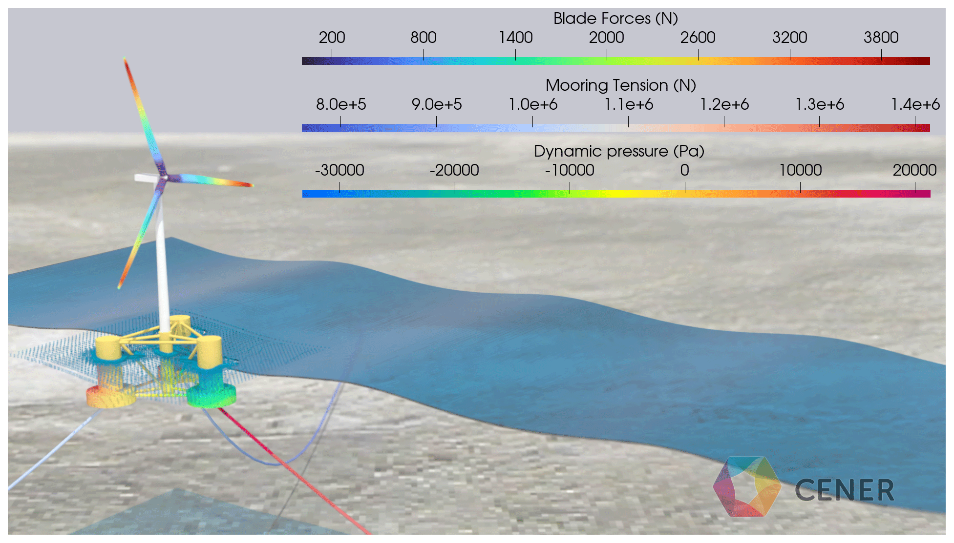
Figure 1Visualization of an OF2 simulation. The forces on the blades are shown alongside the mooring line tension and the dynamic pressure on the platform.
Moreover, in the design and certification process of FOWTs, following standards such as the IEC 61400-3-2 Ed1 (International Electrotechnical Commission, 2019) or NI572 (Bureau Veritas, 2019), the hydrodynamic pressure over the surface of the platform may be requested alongside the loads at the tower base or mooring tensions at the fairleads for different cases with the wind turbine in a normal operational state, storms or under fault conditions. Even more, some specific FOWT designs equipped with single-point mooring (SPM) may have large rotations in order to weather vane with the wind, which can violate some limitations or assumptions of the state-of-the-art design codes like OpenFAST (see Jonkman, 2009). Therefore, a new simulation tool is presented in this work, called OF2, which combines a high-fidelity representation of the hydrodynamic behavior of the floating platform with an aero-servo-elastic representation of the tower and rotor nacelle assembly. This approach reduces the computational time with regard to full CFD simulations of FOWTs, allowing us to introduce the control system into the simulation and include flexible responses of the different FOWT components. The dynamic pressure, mooring tension, wave run-up and body forces can be obtained as in the visualization example that has been represented in Fig. 1.
The rest of the article is organized as follows: the methodology used to couple OpenFAST and OpenFOAM is defined in Sect. 2, and then the verification methodology is included in Sect. 3. It includes, firstly, the description of the simulated load cases to demonstrate the applicability of the method and the advantages with regard to potential codes or fully resolved CFD simulations. Secondly, the FOWT model used to test OF2 is described as well as the simulation setup and the results. Finally, the conclusions of this work are presented in Sect. 4.
In this work OpenFAST and OpenFOAM are coupled in order to better simulate the floating platform's hydrodynamic response and to overcome engineering model limitations. With the following approach, the aero-servo-elastic response of the wind turbine is simulated with OpenFAST, while the floating platform dynamics and fluid flow are simulated with OpenFOAM. The resulting tool has been named OF2.
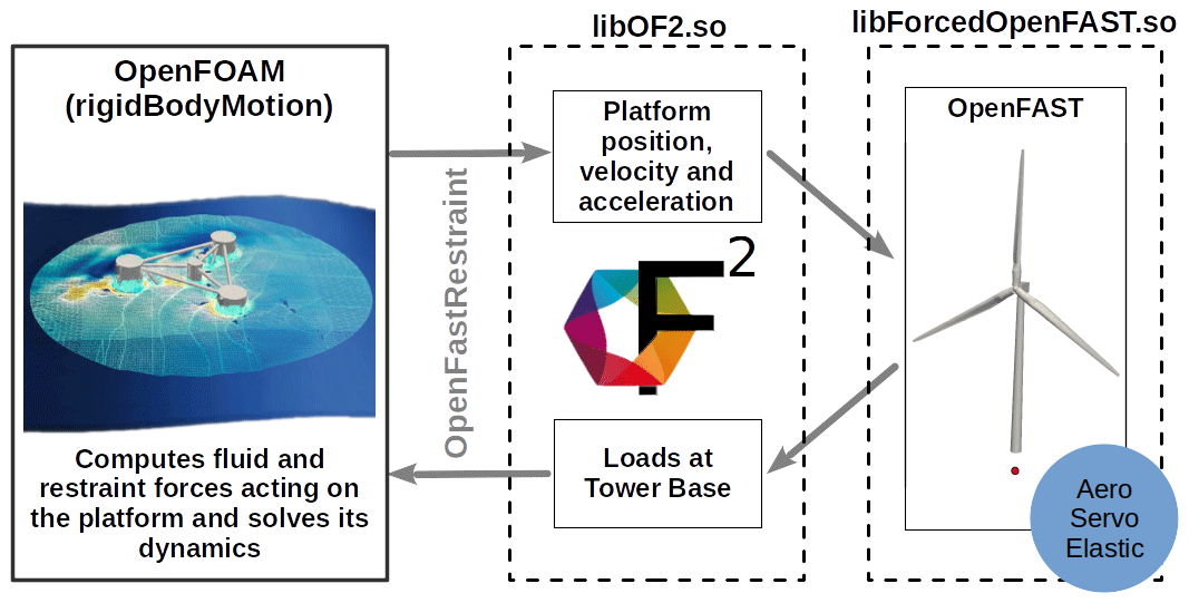
Hence, this OF2 environment has been made through the development of two new shared libraries. The operation scheme of all the OF2 libraries within OpenFOAM can be seen in Fig. 2. Firstly, libForcedOpenFAST.so has been developed. This library allows us to run OpenFAST, imposing the floating platform displacements (see Martín-San-Román, 2022, for the details of the imposition of movements in OpenFAST). Secondly, a new rigid-body-motion-type restraint, named libOF2.so, has also been created. This libOF2.so restraint uses the functions existing inside libForcedOpenFAST.so in order to apply the loads computed by OpenFAST on the rigid body, i.e., the floating platform. Therefore, at each time step, the floating platform dynamics is solved by the rigid body motion library within OpenFOAM. When the OF2 restraint is executed, it uses the displacement, velocity and acceleration of the floating platform as an input for the functions of libForcedOpenFAST.so that impose this displacement onto the wind turbine modeled within OpenFAST and that calculate the corresponding loads, power and deformations of the different wind turbine components. Finally, the loads at the tower base point are then applied to OpenFOAM's body, along with the ones resulting from the other restraints (like mooring lines or external forces if any) and fluid forces. Once the platform's dynamics response is solved, the mesh is updated and adapted to the new platform's position, and the fluid flow is solved finishing the current time step iteration. This approach ensures that the effect of the platform dynamics on the tower and rotor nacelle assembly is considered in the servo, elastic and aerodynamic responses of each of these components and vice versa. An example of a simplified dynamicMeshDict file used in OpenFOAM to describe the body dynamics using the new shared libraries can be seen in Appendix A.
3.1 Load cases
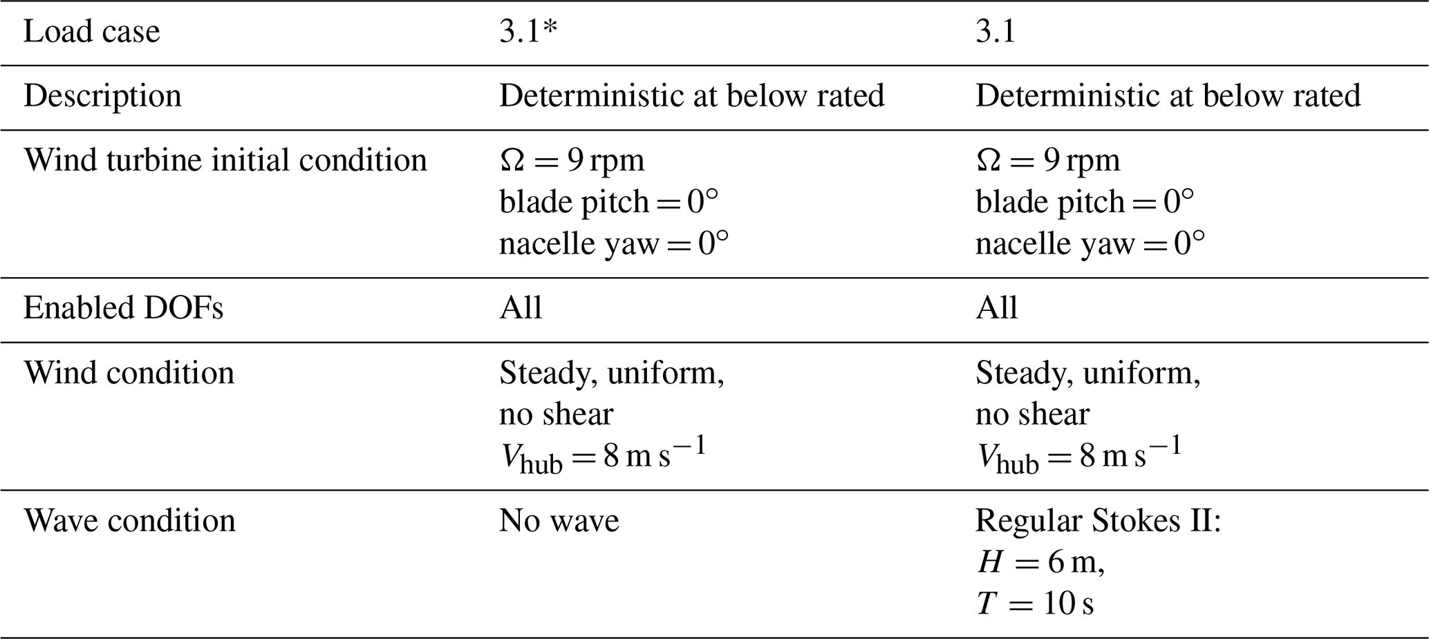
In order to verify OF2, two verification load cases have been evaluated with OF2 and an OpenFAST-only approach. The two cases have been based on load case (LC) 3.1 of the OC4 project (Robertson et al., 2014b), with a steady uniform (deterministic) wind speed of 8 m s−1, a regular wave height (H) of 6 m and a period (T) of 10 s. In the first load case analyzed in this work, called 3.1*, no waves have been included. All the main characteristics of these two load cases have been summarized in Table 1.
Table 1Description of the load cases analyzed, adapted from OC4 Phase II (Robertson et al., 2014b).
3.2 Simulation setup
The new tool, OF2, has been used to evaluate the response under wind and wave loading. For this study, OpenFAST v2.6.0 and OpenFOAM v21.06 have been coupled to model the NREL 5 MW wind turbine on the OC4 semi-submersible DeepCWind floating platform (see Jonkman et al., 2007, and Robertson et al., 2014a).
The tower and rotor nacelle assemblies have been modeled considering the flexibility of the different components. For the three blades, two flexible modes in the flapwise direction and one in the edgewise direction have been considered. Additionally, for the drivetrain, a torsional mode has been included, and two flexible modes have also been considered, in both the fore–aft direction and the side–side direction, to represent the flexible response of the tower. The floating platform is considered to be a fully rigid structure. Furthermore, an in-house controller designed for this FOWT has been used.
Moreover, the mooring system has been simulated using MoorDyn (see Hall, 2017) and OpenFOAM's restraint developed by Chen and Hall (2022). This restraint has been modified to work together with OpenFOAM's rigid body motion library, and it has been called libmoordynRestraint.so. The way to include this new restraint in the dynamicMeshDict is also included in Appendix A.
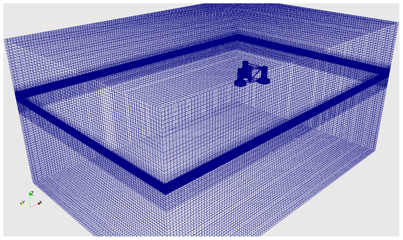
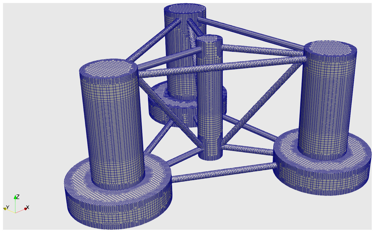
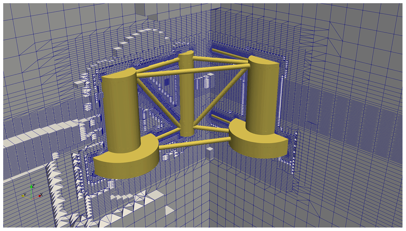
For the CFD simulations performed inside OF2, an unstructured mesh has been created with snappyHexMesh, where the domain size is 581/403/278 m in the surge, sway and heave directions. The smaller element on the platform's surface mesh has a size of between 0.3 and 0.6 m, and no boundary layer has been added close to the body. Three refinement regions have been used: the first is a box around the floating platform where the mesh size is 0.6 m in the vertical direction with an aspect ratio of 4, and the other two are boxes located around the still-water level, ensuring a minimum of 20 cells per wave height and 50 cells per wave length, as suggested in Connell and Cashman (2016). These settings result in 2.3 million element meshes. Different mesh details are shown in Figs. 3 (overall view), 4 (platform body view) and 5 (platform surrounding view).
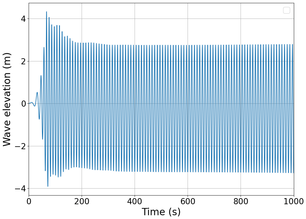
Regarding the numerical schemes used, first-order implicit laminar simulations with OpenFOAM v21.06 have been done. In particular, Gauss linear spatial schemes, for the gradient terms, and Gauss upwind and Gauss MUSCL schemes, for the divergence terms, have been used. Moreover, the MULES interface-capturing scheme has been selected. Finally, the PIMPLE algorithm has been used to solve the pressure–velocity coupling. The under-relaxation factors for both velocity and pressure have been set to 1. In order to take into account the displacements, a dynamic mesh approach is required to perform the simulation. Additionally, the displacement Laplacian, as the motion solver, and the moving wall, as the boundary condition in the floating platform, have been used. With an implicit algorithm the mesh morphing is updated at each iteration driven by the platform dynamics. Finally, the boundary conditions used are wave velocity inlet and pressure outlet in the inlet and outlet boundaries, the ground is considered a wall, and the domain sides are modeled with a slip condition. Moreover, the boundary condition used for wave generation uses a ramp timescale factor to avoid numerical divergence. In order to absorb the waves at the outlet, the shallowWaterAbsorption boundary condition has been used; this boundary condition applies a 0 gradient condition to the phase field and to the vertical component of the velocity, while it sets the other two velocity components to 0. For the floating platform the movingWallVelocity boundary condition is used. The resulting wave elevation profile has an initial transitory state where the wave amplitude is gradually increased. This transient evolution is shown in Fig. 6.
In order to analyze the OF2 performance, an OpenFAST-only model for comparison purposes has been created to define the integrated model of the FOWT. It has to be noted that the OpenFAST model for the tower and rotor nacelle assembly (RNA) is the same in the OpenFAST-only model and the coupled tool OF2. In particular, the same blade element model (BEM) approach has been applied to compute the aerodynamic loads at the rotor, and the same wind files have been used in both simulations. The ElastoDyn representation of the tower and rotor nacelle assembly in OpenFAST is the same as that used in the OF2 solver. The same MoorDyn input files have been used for both simulations. It should be noted that the wave elevation signal used in the OpenFAST simulation of LC 3.1 has been extracted from an empty channel simulation performed with OpenFOAM, that is, from a simulation of the sea state without the floating platform. This wave elevation signal monitored at the platform's initial reference point (x=0 m) is used by OpenFAST to determine the loads that the waves exert onto the platform along the whole simulation. Therefore, the waves that affect the dynamics of both OpenFAST and OF2 simulations should be comparable, even though the actual wave in the OF2 approach is three-dimensional.
In the OpenFAST-only simulations, the platform's hydrodynamic response has been represented through the HydroDyn module (see Jonkman, 2009) with a combination of the potential flow and Morison equation. The drag coefficient of the members range between 0.56 and 0.68, depending on the diameter, as is defined in Robertson et al. (2017). A drag coefficient of 9.6 has been used for the heave plates, using the plate area as reference to compute the force. Non-linear hydrodynamics has been included using full quadratic transfer functions (QTFs). The LC 3.1* case has a simulation time of 400 s and LC 3.1 of 1000 s, both of them with a time step of 0.01 s. The OF2 simulations have been run on one node equipped with a dual AMD EPYC 7543 32-core processor and 128 GB of RAM.
3.3 Results
Hereafter, the results obtained by both approaches, OpenFAST only and OF2, are compared. Firstly, the time series results of the platform's degrees of freedom (DOFs) and loads are compared in order to have a qualitative comparison of the results obtained from both OF2 and OpenFAST-only approaches. Then, a quantitative comparison of the mean and standard deviation values of these DOFs is performed.
3.3.1 Still-water case: LC 3.1*
The results corresponding to the still-water case, LC 3.1*, can be seen in Fig. 7. This figure includes the results obtained for surge (top), heave (middle) and pitch (bottom) motions (left column) and the respective loads (right column).
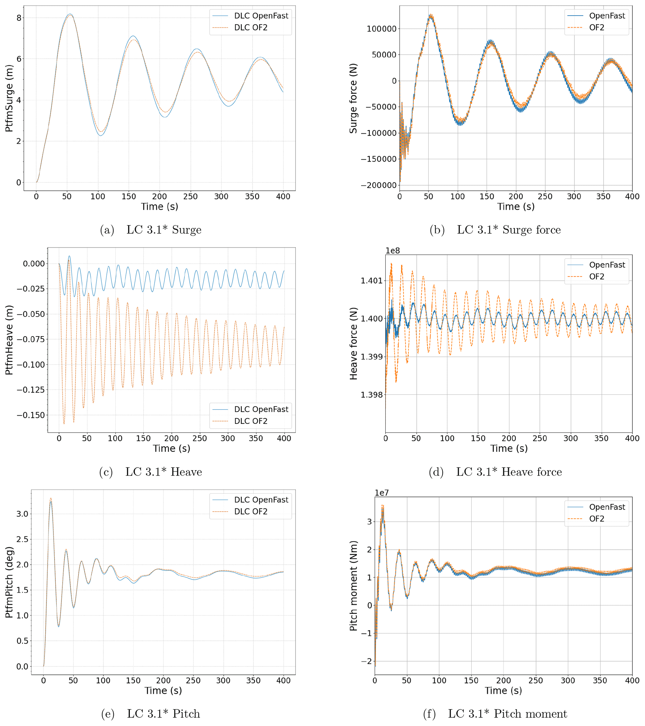
Figure 7Platform responses (a, c, e) and hydrodynamic loads (b, d, f) in surge (a, b), heave (c, d) and pitch motions (e, f), as well as degrees of freedom in the still-water case, LC 3.1*. The results obtained with OpenFAST have been presented in blue, while those obtained with OF2 have been represented in orange.
As can be seen in Fig. 7a, c and e, OF2 is able to properly model the dynamic behavior of the FOWT. The surge motions for both of the compared approaches present similar values in terms of the period, mean value and amplitude. However, slight differences in the amplitude arise due to the different modeling of hydrodynamic loads. For the heave response, it must be noted that there is a difference of less than 0.1 m between the mean value of both simulations. It is considered that this offset of around 0.5 % of the platform's draft is caused by the difference in the submerged volume. In OF2 this volume is not user defined but is a result of the surface mesh employed – using a different refinement on the surface mesh would lead to a smaller heave offset, but this deviation can be assumed to be negligible. The comparison between the pitch responses demonstrates the OF2 feasibility, and, therefore, it can be assumed that the OF2 approach is verified.
Figure 7b, d and f compare the resulting hydrodynamic loads acting on the platform for each modeling approach for the deterministic case without waves, LC 3.1*. Note that moments are computed with regard to the platform reference point. In particular, the loads computed under the OF2 approach are those exerted by the fluid on the platform, i.e., both the hydrodynamic and the hydrostatic loads. The demanded load outputs under the OpenFAST approach are the integrated hydrodynamic loads, and they also take hydrostatic forces into account. Therefore, it must be noted that both approaches determine similar mean loads and that the surge force and pitch moment are very similar. The small-scale differences in the heave force amplitudes are caused by the larger motions of the OF2 simulation, which is initialized at a farther position from its equilibrium, compared to the OpenFAST-only simulation. A comparison of the disaggregated loads (hydrostatic and hydrodynamic) has also been performed, showing the same trend.
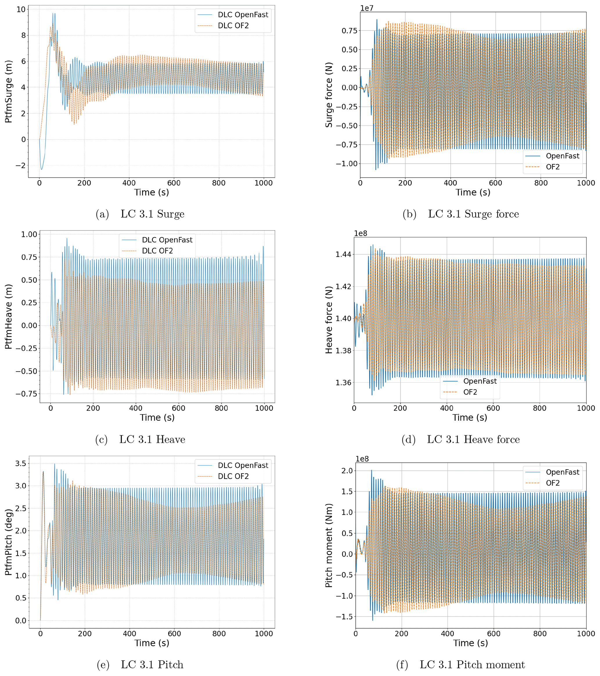
Figure 8Platform response (a, c, e) and hydrodynamic loads (b, d, f) in surge (a, b), heave (c, d) and pitch motions (e, f), as well as degrees of freedom in the regular wave case, LC 3.1. The results obtained with OpenFAST have been presented in blue, while those obtained with OF2 have been represented in orange.
3.3.2 Regular wave case: LC 3.1
The regular wave case (LC 3.1) time series are presented in Fig. 8, following the same scheme as for the previous case, showing the platform's degrees of freedom in the left column and the hydrodynamic loads in the right column.
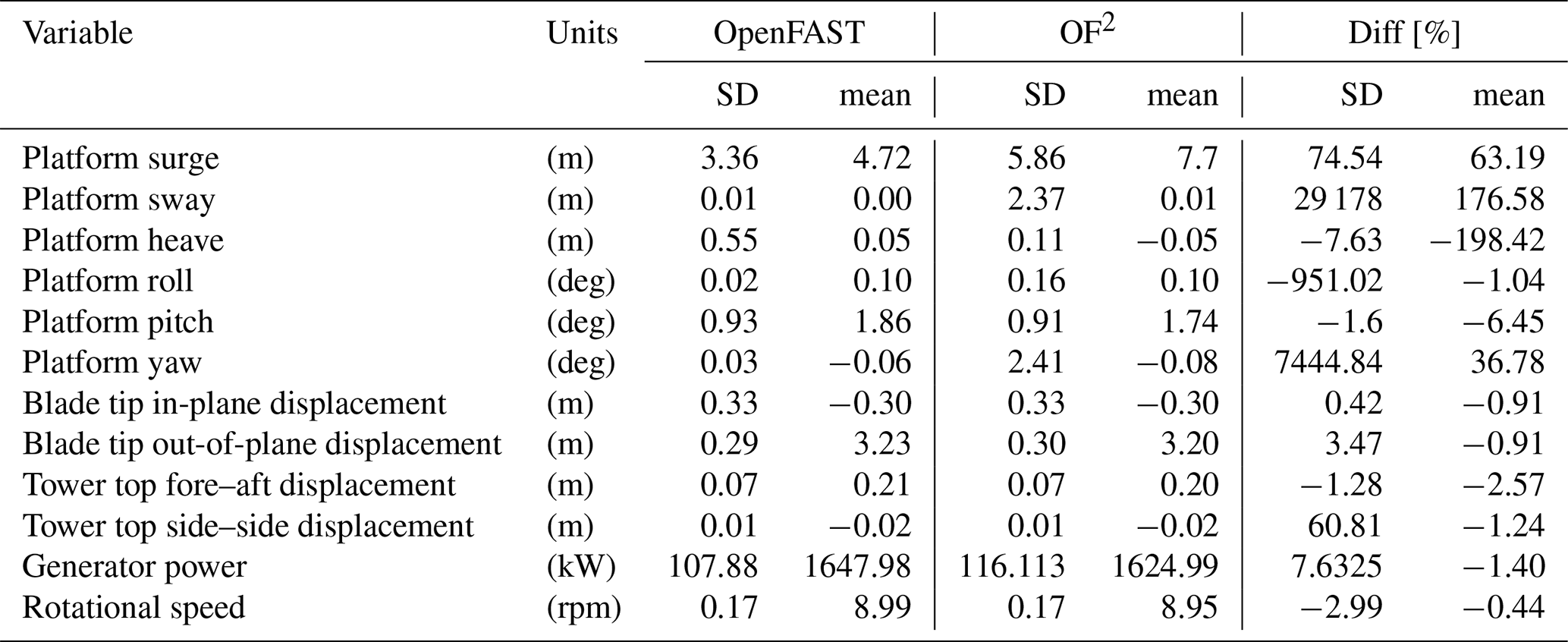
Table 2Statistical results of the different variables analyzed for the load case under wind and waves, LC 3.1. The standard deviation (SD) and the mean values (mean) for each model used, OpenFAST and OF2, have been included alongside the normalized differences obtained between the two models following Eq. (1).
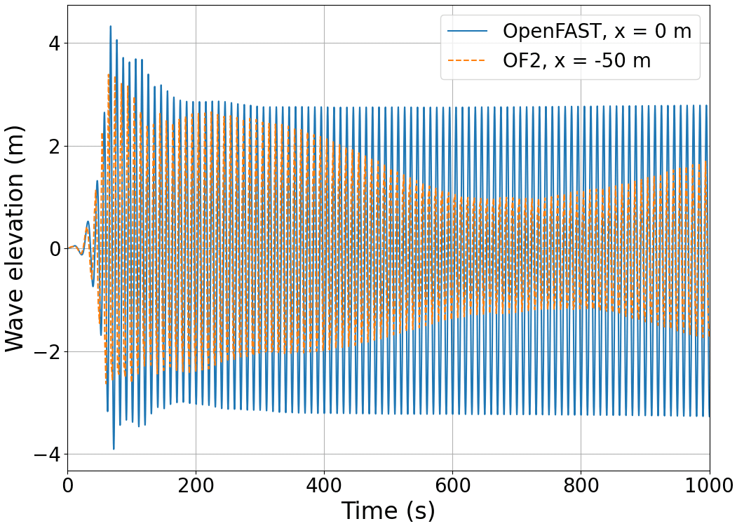
When the wave excitation is considered (LC 3.1) on platform motions (Fig. 8a, c and e), differences arise mainly at the signal amplitude. The surge motion, which is mainly driven by wind load, has a different initial transient behavior. This is due to the initialization of the OpenFAST-only approach. Once both of the approaches are close to the stationary state the surge behavior becomes similar. Fig. 8c shows a different mean heave value. This responds to the same offset that has previously been seen in the LC 3.1* case. However, the pitch motion in OF2 shows an amplitude modulation that is not appreciated in the previous degrees of freedom (Fig. 8a and c), while it presents a similar mean value to the OpenFAST result. If the loads are analyzed (Fig. 8b, d and f), this modulation is also observed in the pitching moment. This is caused by how the wave evolves in OF2. In order to show this effect, the wave elevation time series from both the empty channel (represented in blue and used in OpenFAST) and the OF2 simulation (represented in orange and measured 50 m upstream of the platform) have been included in Fig. 9. In Fig. 9 an amplitude modulation is also observed on the OF2 wave elevation signal, which leads to the unexpected behaviors mentioned previously. Before running the OF2 simulation, the wave generation and numerical schemes were calibrated at the origin position in an empty numerical wave tank. The free surface elevation was not sampled in any other location. Due to the amplitude modulation, the wave generation test was performed again, and the same modulation 50 m upstream of the platform was seen. Numerical wave-makers have many sources of uncertainties and are the subject of many studies, as shown in Windt et al. (2019). In the present work, static boundary methods have been used for both wave generation and absorption. In their research, Windt et al. (2019) found that static boundary methods were outperformed by relaxation zone methods. This may be due to the assumption of shallow-water conditions for wave absorption. Wave modulation is related to the wave generation method employed, and it should be improved in order to obtain the desired regular wave. Furthermore, these inconsistencies in the wave elevation mean that this OF2 result is not directly comparable with the results of Robertson et al. (2014a) in terms, for example, of the phase shift between the wave and the hydrodynamic forces in heave or pitch. Moreover, floating offshore wind turbines demand a long time of simulation, which has been found (Larsen et al., 2019) to require suitable numerical schemes in order to keep the wave shape during the whole simulation. Considering all the aforementioned factors, it is asserted that wave generation and absorption hold utmost significance in FOWT simulations. Accordingly, a thorough calibration of the numerical wave tank should always be performed.
Nevertheless, since the OF2 approach solves the fluid domain, the pressure distribution on the platform surface, among other outputs, is available for further analysis, reinforcing the suitability of this tool for co-design processes, and also to support certification processes. For example, in Fig. 10, the dynamic pressure distribution over the floating platform is shown at a particular instant of the simulation. In addition to the high-fidelity simulation of the platform dynamics, with OF2 it is also possible to include the control and flexibility response of the wind turbine with a lower computational effort than with a fully flexible CFD approach. Therefore, the flexible response predicted by OF2 at the tower top and the blade tip locations have been compared against OpenFAST-only simulations in Figs. 11 and 12, respectively, only for LC 3.1 with regular wave. The comparison of these variables for the still-water case is not included for the sake of simplicity. In these figures it can be seen that the differences in amplitude, especially for the pitch platform rotation that has previously been observed in Fig. 8e, are also visible in the tower top fore–aft displacement and blade tip out-of-plane deflection in Figs. 11a and 12a, respectively.
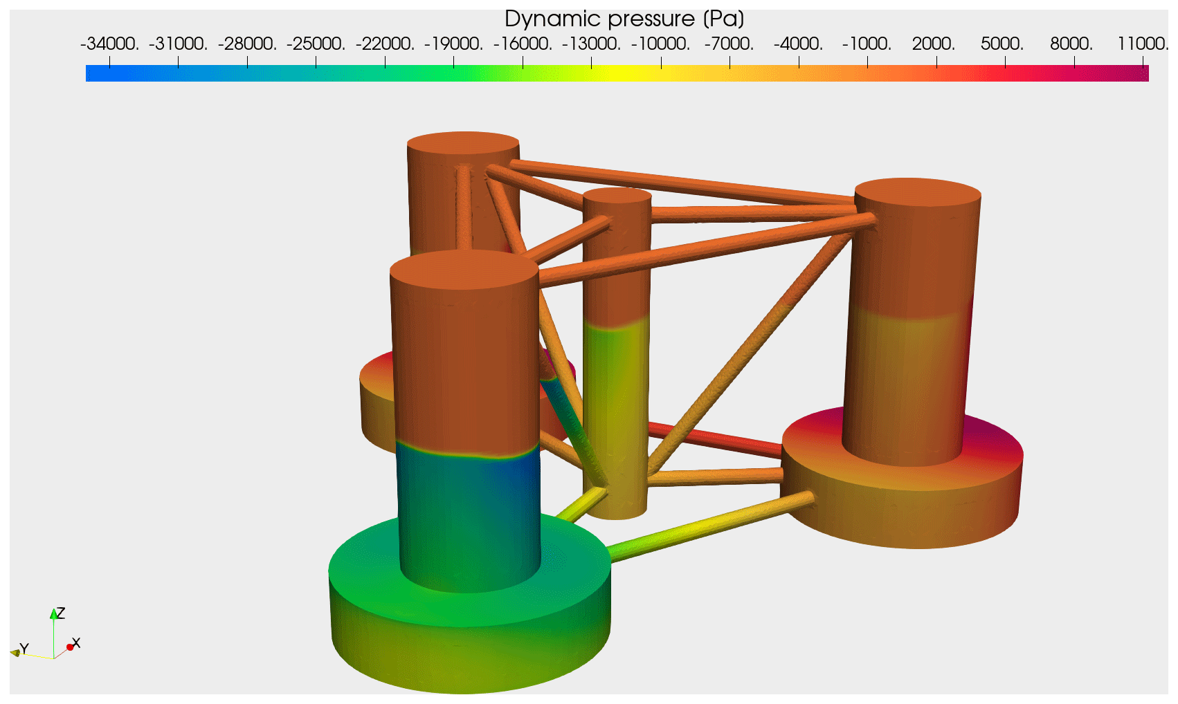
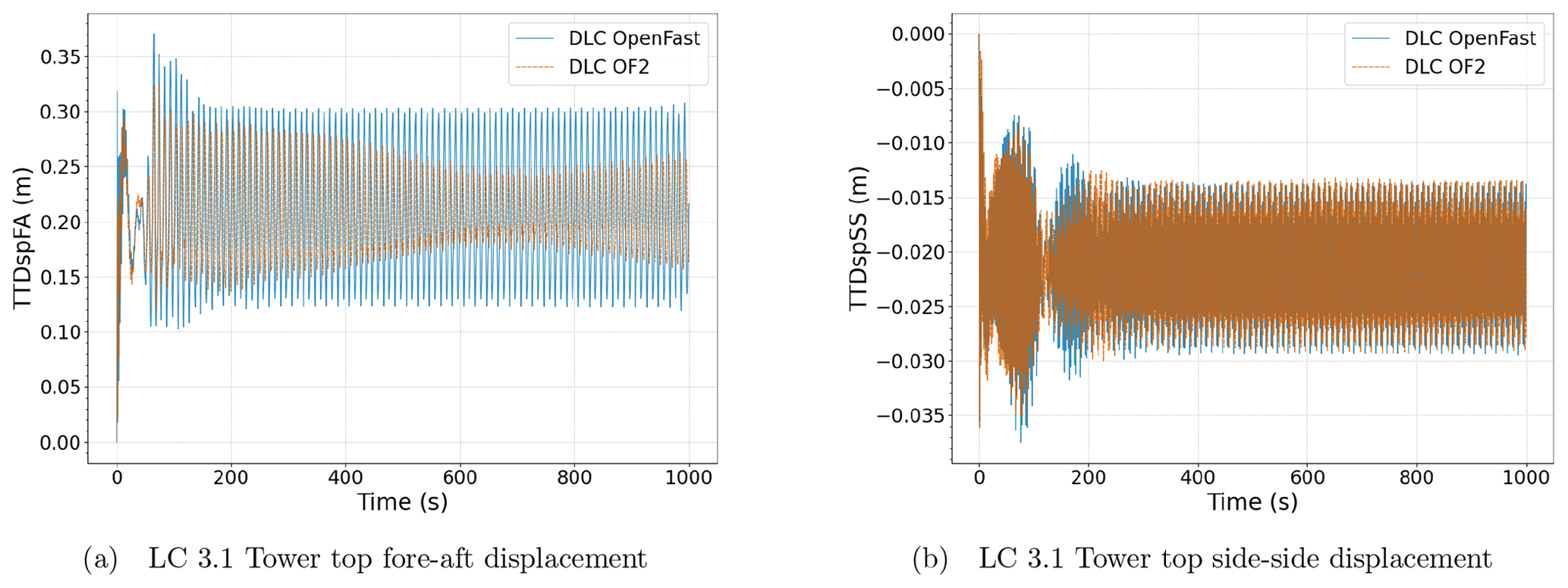
Figure 11Tower top deformations for the regular wave case, LC 3.1. Tower top fore–aft deflection (a) and tower top side–side deflection (b). The results obtained with OpenFAST have been presented in blue, while those obtained with OF2 have been represented in orange.
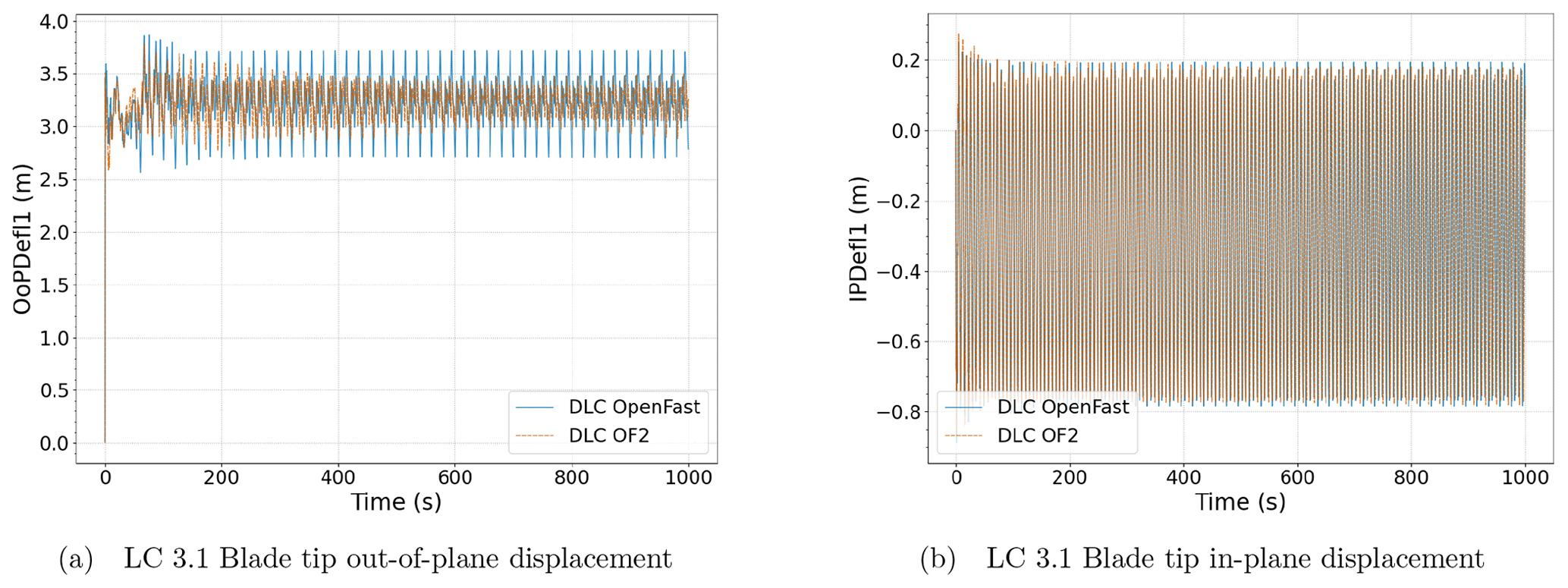
Figure 12Blade tip deformations for the regular wave case, LC 3.1. Blade tip out-of-plane deflection (a) and blade tip in-plane deflection (b). The results obtained with OpenFAST have been presented in blue, while those obtained with OF2 have been represented in orange.
Moreover, the control performance for the regular wave case LC 3.1 is presented in Fig. 13. Both rotational speed (Fig. 13a) and generator power (Fig. 13b) present a slightly lower mean value and a smaller amplitude in OF2 than in the OpenFAST-only approach. These deviations are due to the differences in the FOWT movements.
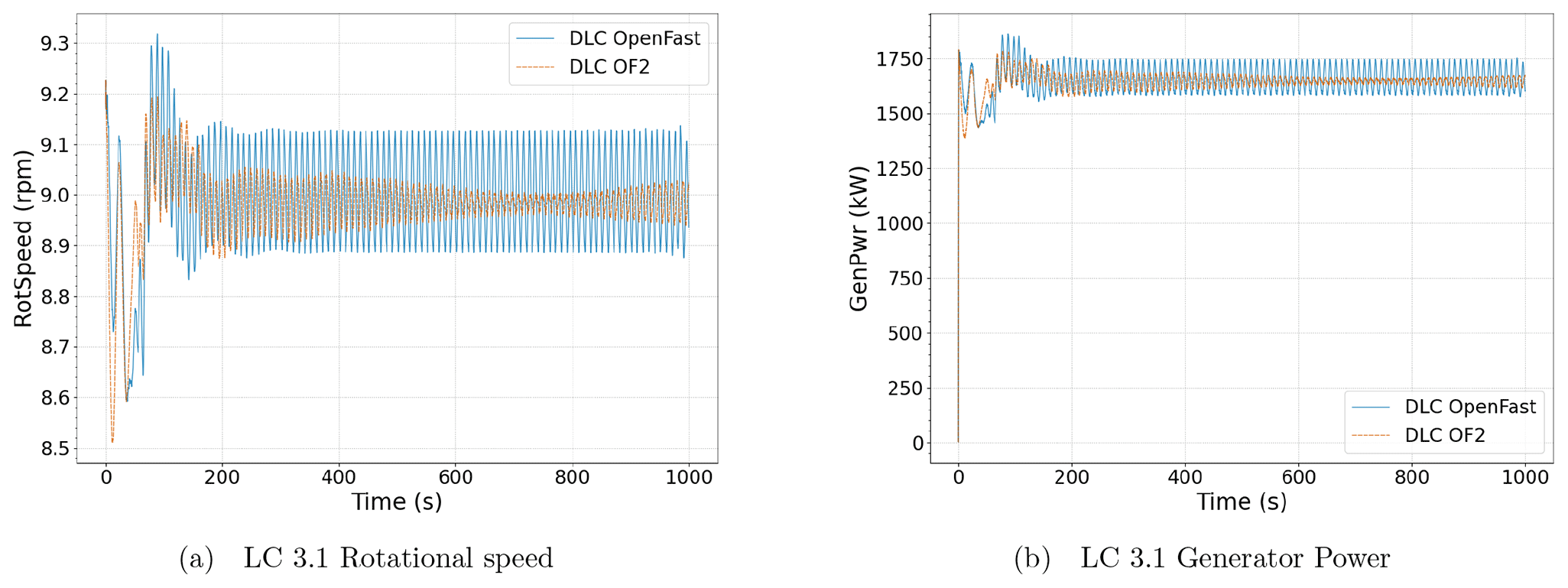
Figure 13General regulation variables for the regular wave case, LC 3.1. The rotational speed (a) and the generator power (b). The results obtained with OpenFAST have been presented in blue, while those obtained with OF2 have been represented in orange.
Finally, the statistical analysis of all these time signals has been included in Table 2. In this table, the standard deviation (SD) and the mean values (mean) for the two approaches compared in this work have been included. Additionally, the differences obtained between the two models have been quantified in terms of normal differences as shown in Eq. 1:
Therefore, with this metric, if the difference is a positive value, it means the value in OF2 is higher than in the OpenFAST-only results. This metric has been applied for both the standard deviation and the mean value. It can be noted in Table 2 that the higher differences between OF2 and OpenFAST-only approaches are obtained in platform sway and heave DOFs. However, as these degrees of freedom have a very small range, it must be stated that the actual difference (without normalizing) is less than 10 mm in sway and 10 cm in heave. Although there have been shortcomings in wave generation, which can be further improved by employing alternative techniques, the presented metrics unequivocally establish the validity of the novel OF2 tool for the assessment of floating offshore wind turbines.
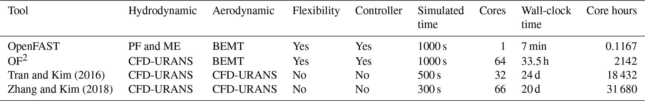
The approach proposed in this work, using OF2 to perform coupled simulations of floating offshore wind turbines, presents advantages both over the lower-complexity resolution and over other high-fidelity approaches found in the literature. For example, when comparing OF2 capabilities with potential flow hydrodynamic solvers, OF2 allows us to include higher-order terms and viscous effects that are more difficult to fit in lower-complexity models like HydroDyn. Moreover, OF2 will allow us to overcome the limitation of HydroDyn that assumes small rotations for the platform response, thereby applying the hydrodynamic loads without updating these rotations and taking into account the actual position of the free surface. This advantage makes OF2 a recommendable tool for detailed analysis of the response of concepts equipped with SPM since they do not have any restrictions for rotation around the vertical axis. Additionally, OF2 presents lower computational costs than other fully coupled high-fidelity simulations found in the literature. Table 3 has been included to quantify this difference in computational cost. This table specifies the following for each tool used in this study and for those from Tran and Kim (2016) and Zhang and Kim (2018): some details of the modeling methodology, the number of cores used for the simulation, the simulated time and the time it took to complete the simulation. As can be seen, OF2 has a much higher computational cost than the OpenFAST-only approach. However, it still allows 10 min load simulations to be carried out in less than 1 d. Moreover, with OF2, detailed simulations of complex cases can be addressed using less than 6 % of the computational resources necessary for a complete CFD approach for both aero- and hydrodynamics. Nevertheless, the computational cost in any CFD study depends mainly on the refinement of the mesh and the influence, for example, of certain calculation options. For instance, the meshes used in this study with OF2 do not have prismatic boundary layers, so the computational cost might not be fully comparable with those used in Tran and Kim (2016) or Zhang and Kim (2018).
Tran and Kim (2016)Zhang and Kim (2018)Table 3Computational cost of different tools used for the coupled analysis of FOWT under wind and wave loading.
A new simulation tool, called OF2, for time domain simulations of FOWT has been developed. The main conclusions of this work can be summarized as follows:
-
OF2 combines a high-fidelity resolution of the hydrodynamic response of a floating platform with a multi-complexity aero-servo-elastic tool for the simulation of the wind turbine.
-
With the coupling of OpenFAST to a CFD simulation of the platform hydrodynamics, all the potential from OpenFAST can be used to introduce the wind turbine component flexible behavior, the turbulent winds and the control laws necessary for the FOWT operation.
-
The new tool has the advantage of reducing the computational time with regard to the use of a full CFD approach that includes the turbine aerodynamics.
-
Load cases with large platform displacements and wind turbine operation events can be simulated with OF2. Current engineering tools present limitations in accurately capturing the effect of large displacements, and state-of-the-art CFD simulations typically consider rigid rotors.
-
OF2 has been verified in this study against OpenFAST-only simulations. The OC4 semi-submersible floating platform (Robertson et al., 2014a) and the NREL 5 MW wind turbine (Jonkman et al., 2007), under co-directional wind and wave loading, have been used in this verification. The results have shown that the principal platform's degrees of freedom present very similar mean values between the OF2 and the OpenFAST-only approaches, in particular for the wind-only cases. Once the regular waves are introduced, higher differences arise, especially for the heave and pitch motions. It is likely that these differences are caused by a undesired loose of the wave amplitude in the OF2 simulation. Further research in wave modeling should be done to improve the OF2 results.
-
In addition, as OF2 solves the complete fluid domain, it provides a detailed representation of the distributed magnitudes on the platform surface, which can be useful for the calculation and design process. For example, the pressure distribution at the platform components and the loads from the tower, the anchoring system, etc., can be obtained simultaneously.
-
OF2 could be used as part of the FOWT co-design techniques to optimize the design and, therefore, contribute to the reduction in LCOE of offshore wind energy.
-
With OF2, an advance in the state of the art of simulation codes for FOWTs has been done. This will support the offshore wind energy cost reduction needed to boost the maturity of floating offshore wind energy.
In future work, OF2 will be used to analyze SPM designs to study weather-vaning responses under co-directional and misaligned wind and wave loading. Moreover, OF2 will be used to obtain the required distributed loads over the platform surface, along with the loads from the fairleads and tower base, to be used in a structural simulation tool for the analysis of ultimate and fatigue loads over the floating structure. OF2 will also be coupled with MUST (Martín-San-Román, 2022), an in-house tool based on OpenFAST, for the coupled analysis of multiple wind turbine floating platforms. This will allow analyzing the response of these types of configurations when equipped with SPM. MUST includes a free vortex filament method (FVM) module for the rotor aerodynamics, which will provide more accurate predictions of aerodynamic loads under the misaligned conditions that arise in large displacements of the system.
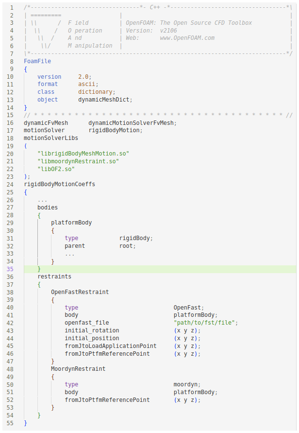
Listing A1Configuration template for the OF2 and MoorDyn restraints in the dynamicMeshDict file.
Data will not be available a priori. If the data are needed for research or comparison purposes, the authors will be glad to share them upon request.
GCA: tool development, methodology definition, verification, OF2 simulations and writing. RMSR: tool development, verification, methodology definition, OpenFAST simulations and writing. PBC: tool development, methodology definition and verification. BML: funding acquisition, conceptual definition and writing. JAA: results analysis, verification and writing.
The contact author has declared that none of the authors has any competing interests.
Publisher’s note: Copernicus Publications remains neutral with regard to jurisdictional claims in published maps and institutional affiliations.
This research has been supported by the Gobierno de Navarra (grant no. 0011-1383-2022-000000).
This paper was edited by Erin Bachynski-Polić and reviewed by two anonymous referees.
Azcona, J.: Computational and Experimental Modelling of Mooring Line Dynamics for Offshore Floating Wind Turbines, PhD thesis, Universidad Politécnica de Madrid, https://doi.org/10.20868/UPM.thesis.39817, 2016. a
Bergua, R., Robertson, A., Jonkman, J., Branlard, E., Fontanella, A., Belloli, M., Schito, P., Zasso, A., Persico, G., Sanvito, A., Amet, E., Brun, C., Campaña-Alonso, G., Martín-San-Román, R., Cai, R., Cai, J., Qian, Q., Maoshi, W., Beardsell, A., Pirrung, G., Ramos-García, N., Shi, W., Fu, J., Corniglion, R., Lovera, A., Galván, J., Nygaard, T. A., dos Santos, C. R., Gilbert, P., Joulin, P.-A., Blondel, F., Frickel, E., Chen, P., Hu, Z., Boisard, R., Yilmazlar, K., Croce, A., Harnois, V., Zhang, L., Li, Y., Aristondo, A., Mendikoa Alonso, I., Mancini, S., Boorsma, K., Savenije, F., Marten, D., Soto-Valle, R., Schulz, C. W., Netzband, S., Bianchini, A., Papi, F., Cioni, S., Trubat, P., Alarcon, D., Molins, C., Cormier, M., Brüker, K., Lutz, T., Xiao, Q., Deng, Z., Haudin, F., and Goveas, A.: OC6 project Phase III: validation of the aerodynamic loading on a wind turbine rotor undergoing large motion caused by a floating support structure, Wind Energ. Sci., 8, 465–485, https://doi.org/10.5194/wes-8-465-2023, 2023. a
Bladed: Bladed Theory Manual Version 4.0,, Garrad Hassan & Partners Ltd., St Vincent’s Works, Silverthorne Lane, Bristol BS2 0QD England, https://www.gl-garradhassan.com (last access: May 2023), 2010. a
Bossanyi, E., Burton, T., and Sharpe, D.: Wind Energy Handbook, John Wiley and Sons, Print ISBN 9780470699751, Online ISBN 9781119992714, https://doi.org/10.1002/9781119992714, 2001. a
Branlard, E., Gaunaa, M., and MacHefaux, E.: Investigation of a new model accounting for rotors of finite tip-speed ratio in yaw or tilt, J. Phys. Conf. Ser., 524, 012124, https://doi.org/10.1088/1742-6596/524/1/012124, 2014. a
Bureau Veritas: BV-NI572 – Classification and Certification of Floating Offshore Wind Turbines, 33, https://erules.veristar.com/dy/data/bv/pdf/572-NI_2019-01.pdf (last access: May 2023), 2019. a
Chen, H. and Hall, M.: CFD simulation of floating body motion with mooring dynamics: Coupling MoorDyn with OpenFOAM, Appl. Ocean Res., 124, 103210, https://doi.org/10.1016/j.apor.2022.103210, 2022. a
Connell, K. O. and Cashman, A.: Development of a numerical wave tank with reduced discretization error, Institute of Electrical and Electronics Engineers Inc., 3008–3012, https://doi.org/10.1109/ICEEOT.2016.7755252, 2016. a
Faltinsen, O. M.: Sea Loads on Ships and Offshore Structures, Cambridge University Press, ISBN-10: 0521458706, ISBN-13: 978-0521458702, 1993. a
Hall, M.: MoorDyn User's Guide, Manual, http://www.matt-hall.ca/files/MoorDyn-Users-Guide-2017-08-16.pdf (last access: May 2023), 2017. a
International Electrotechnical Commission: IEC 61400-3-2 Ed. 1.0, Technical Specification, IEC, Geneva, Switzerland, 51 pp., 2019. a
Jonkman, J., Butterfield, S., Musial, W., and Scott, G.: Definition of a 5-MW Reference Wind Turbine for Offshore System Development, Technical Report tp-500-38060, NREL, https://doi.org/10.2172/947422, 2007. a, b
Jonkman, J. M.: Dynamics Modeling and Loads Analysis of an Offshore Floating Wind Turbine, Technical Report, https://doi.org/10.2172/921803, 2007. a
Jonkman, J. M.: Dynamics of Offshore Floating Wind Turbines-Model Development and Verification, Wind Energy, 12, 459–492, https://doi.org/10.1002/we.347, 2009. a, b
Kecskemety, K. M. and McNamara, J. J.: Influence of Wake Effects and Inflow Turbulence on Wind Turbine Loads, AIAA Journal, 49, 2564–2576, https://doi.org/10.2514/1.j051095, 2011. a
Larsen, B. E., Fuhrman, D. R., and Roenby, J.: Performance of interFoam on the simulation of progressive waves, Coast. Eng. J., 61, 380–400, https://doi.org/10.1080/21664250.2019.1609713, 2019. a
Liu, Y., Xiao, Q., Incecik, A., Peyrard, C., and Wan, D.: Establishing a fully coupled CFD analysis tool for floating offshore wind turbines, Renew. Energ., 112, 280–301, https://doi.org/10.1016/j.renene.2017.04.052, 2017. a
Marten, D., Paschereit, C. O., Huang, X., Meinke, M. H., Schroeder, W., Mueller, J., and Oberleithner, K.: Predicting Wind Turbine Wake Breakdown Using a Free Vortex Wake Code, AIAA 2019-2080, AIAA Scitech 2019 Forum, https://doi.org/10.2514/6.2019-2080, 2019. a
Martín-San-Román, R.: Coupled dynamics of multi wind turbine floating platforms, PhD thesis, Escuela Técnica Superior de Ingeniría Aeronáutica y del Espacio, Universidad Politécnica de Madrid (UPM), https://oa.upm.es/72234/ (last access: May 2023), 2022. a, b
Micallef, D. and Rezaeiha, A.: Floating offshore wind turbine aerodynamics: Trends and future challenges, Renew. Sust. Energ. Rev., 152, 111696, https://doi.org/10.1016/j.rser.2021.111696, 2021. a
Morison, J., O'Brien, M., Johnson, J., and Schaaf, S.: The Force Exerted by Surface Waves on Piles, J. Petrol. Technol., 2, 149–154, 1950. a
Newman, J. N.: Marine Hydrodynamics, The MIT Press, ISBN 9780262534826, 1977. a
Otter, A., Murphy, J., Pakrashi, V., Robertson, A., and Desmond, C.: A review of modelling techniques for floating offshore wind turbines, Wind Energy, 25, 831–857, https://doi.org/10.1002/we.2701, 2021. a
Quon, E., Doubrawa, P., Annoni, J., Hamilton, N., and Churchfield, M.: Validation of wind power plant modeling approaches in complex terrain, AIAA Scitech 2019 Forum, San Diego, California, 7–11 January 2019, https://doi.org/10.2514/6.2019-2085, 2019. a
Ren, N., Li, Y., and Ou, J.: Coupled wind-wave time domain analysis of floating offshore wind turbine based on Computational Fluid Dynamics method, J. Renew. Sustain. Ener., 6, 023106, https://doi.org/10.1063/1.4870988, 2014. a
Robertson, A., Jonkman, J., Masciola, M., Song, H., Goupee, A., Coulling, A., and Luan, C.: Definition of the Semisubmersible Floating System for Phase II of OC4, Technical Report TP-5000-60601, NREL, https://doi.org/10.2172/1155123, 2014a. a, b, c
Robertson, A., Jonkman, J., Vorpahl, F., Wojciech, P.and Qvist, J., Frøyd, L., Chen, X., Azcona, J., Uzunoglu, E., Guedes Soares, C., Luan, C., Yutong, H., Pengcheng, F., Yde, A., Larsen, T., Nichols, J., Buils, R., Lei, L., Nygaard, T., Manolas, D., and He: Offshore Code Comparison Collaboration Continuation Within IEA Wind Task 30: Phase II Results Regarding a Floating Semisumersible Wind System, in: International Conference on Ocean, Offshore and Arctic Engineering, San Francisco, California, 8–13 June 2014, OMAE, V09BT09A012, https://doi.org/10.1115/OMAE2014-24040, 2014b. a, b
Robertson, A. N., Wendt, F., Jonkman, J. M., Popko, W., Dagher, H., Gueydon, S., Qvist, J., Vittori, F., Azcona, J., Uzunoglu, E., Soares, C. G., Harries, R., Yde, A., Galinos, C., Hermans, K., De Vaal, J. B., Bozonnet, P., Bouy, L., Bayati, I., Bergua, R., Galvan, J., Mendikoa, I., Sanchez, C. B., Shin, H., Oh, S., Molins, C., and Debruyne, Y.: OC5 Project Phase II: Validation of Global Loads of the DeepCwind Floating Semisubmersible Wind Turbine, Energy Proced., 137, 38–57, https://doi.org/10.1016/j.egypro.2017.10.333, 2017. a, b
Tran, T. T. and Kim, D.-H.: Fully coupled aero-hydrodynamic analysis of a semi-submersible FOWT using a dynamic fluid body interaction approach, Renew. Energ., 92, 244–261, https://doi.org/10.1016/j.renene.2016.02.021, 2016. a, b, c, d
Wang, L., Robertson, A., Jonkman, J., Yu, Y.-H., Koop, A., Borràs Nadal, A., Li, H., Bachynski-Polić, E., Pinguet, R., Shi, W., Zeng, X., Zhou, Y., Xiao, Q., Kumar, R., Sarlak, H., Ransley, E., Brown, S., Hann, M., Netzband, S., Wermbter, M., and Méndez López, B.: OC6 Phase Ib: Validation of the CFD predictions of difference-frequency wave excitation on a FOWT semisubmersible, Ocean Eng., 241, 110026, https://doi.org/10.1016/j.oceaneng.2021.110026, 2021. a, b
Wang, L., Robertson, A., Jonkman, J., Kim, J., Shen, Z.-R., Koop, A., Borràs Nadal, A., Shi, W., Zeng, X., Ransley, E., Brown, S., Hann, M., Chandramouli, P., Viré, A., Ramesh Reddy, L., Li, X., Xiao, Q., Méndez López, B., Campaña Alonso, G., Oh, S., Sarlak, H., Netzband, S., Jang, H., and Yu, K.: OC6 Phase Ia: CFD Simulations of the Free-Decay Motion of the DeepCwind Semisubmersible, Energies, 15, 389, https://doi.org/10.3390/en15010389, 2022a. a
Wang, L., Robertson, A., Kim, J., Jang, H., Shen, Z.-R., Koop, A., Bunnik, T., and Yu, K.: Validation of CFD simulations of the moored DeepCwind offshore wind semisubmersible in irregular waves, Ocean Eng., 260, 112028, https://doi.org/10.1016/j.oceaneng.2022.112028, 2022b. a
Windt, C., Davidson, J., Schmitt, P., and Ringwood, J. V.: On the assessment of numericalwave makers in CFD simulations, Journal of Marine Science and Engineering, 7, 47, https://doi.org/10.3390/JMSE7020047, 2019. a, b
Zhang, Y. and Kim, B.: A Fully Coupled Computational Fluid Dynamics Method for Analysis of Semi-Submersible Floating Offshore Wind Turbines Under Wind-Wave Excitation Conditions Based on OC5 Data, Applied Sciences, 8, 2314, https://doi.org/10.3390/app8112314, 2018. a, b, c, d