the Creative Commons Attribution 4.0 License.
the Creative Commons Attribution 4.0 License.
 | 08 Nov 2023
Refining the airborne wind energy system power equations with a vortex wake model
Filippo Trevisi
Carlo E. D. Riboldi
Alessandro Croce
The power equations of crosswind Ground-Gen and Fly-Gen airborne wind energy systems (AWESs) flying in circular trajectories are refined to include the contribution from the aerodynamic wake, modeled with vortex methods. This reveals the effect of changing the turning radius, the wing geometry and the aerodynamic coefficients on aerodynamic performances and power production. A novel power coefficient is defined by normalizing the aerodynamic power with the wind power passing through a disk with a radius equal to the AWES wingspan, enabling the comparison of different designs for a given wingspan. The aspect ratio which maximizes this power coefficient is finite, and its analytical expression for an infinite turning radius is derived. By considering the optimal wing aspect ratio, the maximum power coefficient is found, and its analytical expression for an infinite turning radius is derived. Ground-Gen and Fly-Gen AWESs, with the same idealized characteristics, are compared in terms of power production, and later three AWESs from the literature are analyzed. With this modeling framework, Ground-Gen systems are found to have a lower power potential than Fly-Gen AWESs with the same geometry because the reel-out velocity makes Ground-Gen AWESs fly closer to their own wake.
- Article
(3593 KB) - Full-text XML
- BibTeX
- EndNote


Airborne wind energy (AWE) is the field of wind energy in which airborne systems, connected to the ground through a tether, harvest high-altitude wind power. Airborne wind energy systems (AWESs) can be classified, based on their flight operations, as crosswind, rotational and tether aligned (Vermillion et al., 2021). The mechanical power can be converted into electrical power on the ground with a moving or fixed ground station (Ground-Gen) or with onboard wind turbines and is transmitted to the ground through the tether (Fly-Gen). In this work, the power equations of Ground-Gen and Fly-Gen crosswind AWESs featuring a single wing are refined.
The first theoretical power equation of crosswind AWESs is derived by Loyd (1980), for given lift and drag coefficients of the system. Other works (e.g., Diehl, 2013; Schmehl et al., 2013; Luchsinger, 2013; Argatov and Silvennoinen, 2013) follow Loyd's effort and refine the power equation, which is still based on given system aerodynamic coefficients. To use these models, the lift and drag coefficients need to be known or modeled. In particular, the lift coefficient is typically modeled as a function of the wing angle of attack, the wing geometry and the airfoil characteristics. A desirable and feasible (i.e., before stall) lift coefficient can be obtained by pitching the wing to obtain the corresponding angle of attack. The system drag includes contributions from the wing profile drag, the tether drag (Trevisi et al., 2020a), the induced drag, and the drag of all AWES components excluding the wing and the tether. The induced drag is the result of the velocities induced by the AWES trailed vorticity (wake) on the AWES wing itself. Indeed, the finite AWES wing trails vortices according to the spanwise lift distribution. The velocities induced by the trailed vortices reduce the relative wind velocity and effectively rotate the apparent velocity, composed by the undisturbed relative wind velocity and the AWES velocity, by an induced angle. Since the aerodynamic lift is defined as being perpendicular to the local apparent velocity, it is rotated by the induced angle. The component of lift parallel to the undisturbed apparent velocity is then the induced drag. In AWE, the induced velocities and the induced drag are typically estimated using Prandtl lifting-line theory, developed for wings in forward flight (i.e., the aerodynamic wake is straight). For example, Vander Lind (2013), Bauer et al. (2018) and Trevisi et al. (2020b) refine Loyd's power equation by finding the induced drag coefficient with the straight wake assumption. To overcome the straight wake assumption in engineering models, the induced velocities are modeled with momentum methods (De Lellis et al., 2018; Kheiri et al., 2018, 2019) and vortex methods (Leuthold et al., 2019; Gaunaa et al., 2020; Trevisi et al., 2023b).
Gaunaa et al. (2020) point out that using momentum methods to analyze the induction for an AWES, which is described by 3D polars, is not physically consistent. Indeed, momentum theory is used in rotor aerodynamics to find the velocity triangle of an airfoil (2D polars) along the blade. If then momentum theory is used to evaluate the induction at an airfoil in the AWES wing (2D polars), a root and a tip correction would be needed to take into account that the rotor is not a disk but a single wing. However, the corrections for AWESs would differ largely from wind turbine corrections, as these are developed for blades extending almost to the rotation axis and need a dedicated study. Gaunaa et al. (2020) then introduce a vortex-based engineering model to find the induced velocities at the AWES. Based on these considerations, Trevisi et al. (2023b) find an induced drag coefficient of the AWES with vortex methods. The helicoidal wake structure is modeled with an expression for the near wake (first-half rotation of the wake) and one for the far wake (from the second half of the wake to infinity). The induced drag related to the near wake is found to be similar to the induced drag the same wing would have in forward flight (i.e., with straight wakes). The induced drag coefficient related to the far wake is modeled as a function of the near-wake drag coefficient, the ratio between the wingspan and the turning radius, and the helicoidal wake pitch. The helicoidal wake pitch can be found iteratively as a function of the other geometrical and aerodynamic quantities. The model is validated with the lifting line free-vortex wake method (Marten et al., 2015) implemented in QBlade.
In this work, a power equation refinement, based on the aerodynamic modeling from Trevisi et al. (2023b), is introduced, and a novel power coefficient is defined. Properly including the aerodynamic wake into the power equation reveals the effect of changing the turning radius, the wing aspect ratio and the aerodynamic coefficients on the overall performance. The novel power coefficient enables the comparison of different concepts and the definition of optimal geometrical quantities. This work is particularly relevant when studying the performance of a given system or carrying out a system design study.
This paper is organized as follows: in Sect. 2, the main assumptions and equations of the vortex model from Trevisi et al. (2023b) are recalled to make this paper self-contained. In Sects. 3 and 4, the power equations of Ground-Gen and Fly-Gen AWESs are derived. In Sect. 5, Ground-Gen and Fly-Gen AWESs, with the same geometry, are compared in terms of power production. In Sect. 6, three AWES designs from the literature are analyzed. In Sect. 7, the main conclusions are discussed. A nomenclature is given in Appendix A.
In this section, the main assumptions and final equations of the vortex wake model introduced by Trevisi et al. (2023b) are summarized. The velocities induced at the AWES from the helicoidal trailed vortex filaments are modeled with an expression for the near wake and one for the far wake. The near wake is modeled as the first-half rotation of the helicoidal filaments, with their axial component being neglected. The far wake is modeled as two semi-infinite vortex ring cascades with opposite intensity. This model is employed to refine the Ground-Gen and Fly-Gen AWES power equations in the next sections.
Referring to Fig. 1, the AWES moves in a circular trajectory with radius R0 in the plane (e1,e2), which is perpendicular to the incoming wind . In this model, the wind is assumed constant, and the gravity is neglected. The AWES has a constant speed, and its wing, assumed to be elliptical, is on the rotational plane. Trevisi et al. (2022a) show that these are the optimal trajectories for a Fly-Gen maximizing thrust power with constant inflow, and the AWES flight mechanics can be studied with respect to this condition (Trevisi et al., 2021). For Ground-Gen AWESs, the inertial reference frame () moves with the reel-out velocity of the tether , assumed to be only along the axial direction such that the relative wind velocity is . For Fly-Gen AWESs, the tether and the inertial reference frame are fixed, and the relative wind velocity coincides with the wind velocity vr=vw.
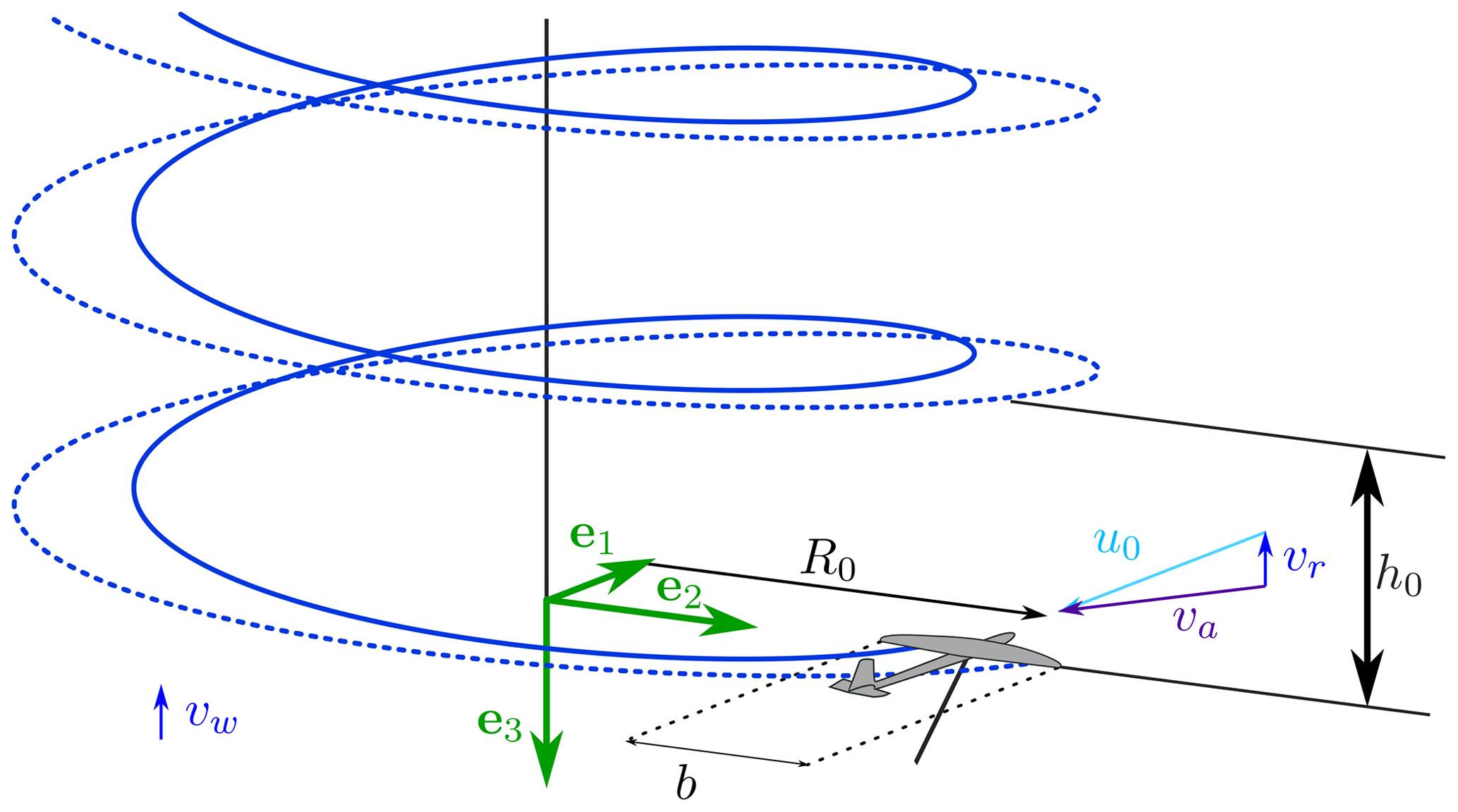
Figure 1Wake structure of an AWES flying in circular trajectories. The solid and dashed blue lines represent the left and right rolled up vortices respectively.
The induced drag coefficient due to the near wake is similar to the induced drag coefficient the same wing would have in forward flight
where CL and AR are the wing lift coefficient and the aspect ratio respectively.
The induced drag coefficient due to the far wake is
where is the inverse turning ratio, defined as the ratio between the half span and the turning radius R0, and λ0 is the normalized torsional parameter of the helicoidal wake, which physically represents the ratio between the circumference length, which is known, and the helix pitch h0, which is unknown:
The system aerodynamic drag coefficient CD is the sum of the parasite drag coefficient CD,p (Anderson, 2017) and the induced drag coefficient CDi:
Cd is the wing profile drag. CD,c contains the drag of the tail surfaces, fuselage, turbine nacelles (if present) and any other component of the AWES exposed to the airflow excluding the tether. is the equivalent tether drag, with CD⟂ being the drag coefficient of the tether section, Dt the tether diameter, Lt the tether length and A the main wing area (Trevisi et al., 2020a).
The system glide ratio is
where CT,t is a coefficient modeling the thrust of the onboard wind turbines, in the case of Fly-Gen AWESs. More details on CT,t are given in Sect. 4.
The axial velocity of the vortex filaments is assumed to be equal to the relative wind velocity vr minus the velocity induced by the near wake , where u0 is the AWES tangential velocity, and the wing speed ratio is defined as the ratio between the AWES tangential velocity and the relative wind speed. Assuming λ2≫1, the helix pitch h0 is
where is the period. The normalized torsional parameter can then be written as
For the AWES to have a constant speed, the lift, perpendicular to the apparent velocity va, combines with the drag, parallel to va, such that the force balance along the AWES longitudinal direction e1 is null. The wing speed ratio λ is then equal to the glide ratio G (see Fig. 2 for Ground-Gen and Fig. 4 for Fly-Gen AWESs). The normalized torsional parameter λ0, necessary for the evaluation of the induced drag due to the far wake (Eq. 2), can be found numerically by setting the residual h of Eq. (7) to 0:
In this section, the power equation of Ground-Gen AWESs, considering the helicoidal wake modeling given in Sect. 2, is derived.
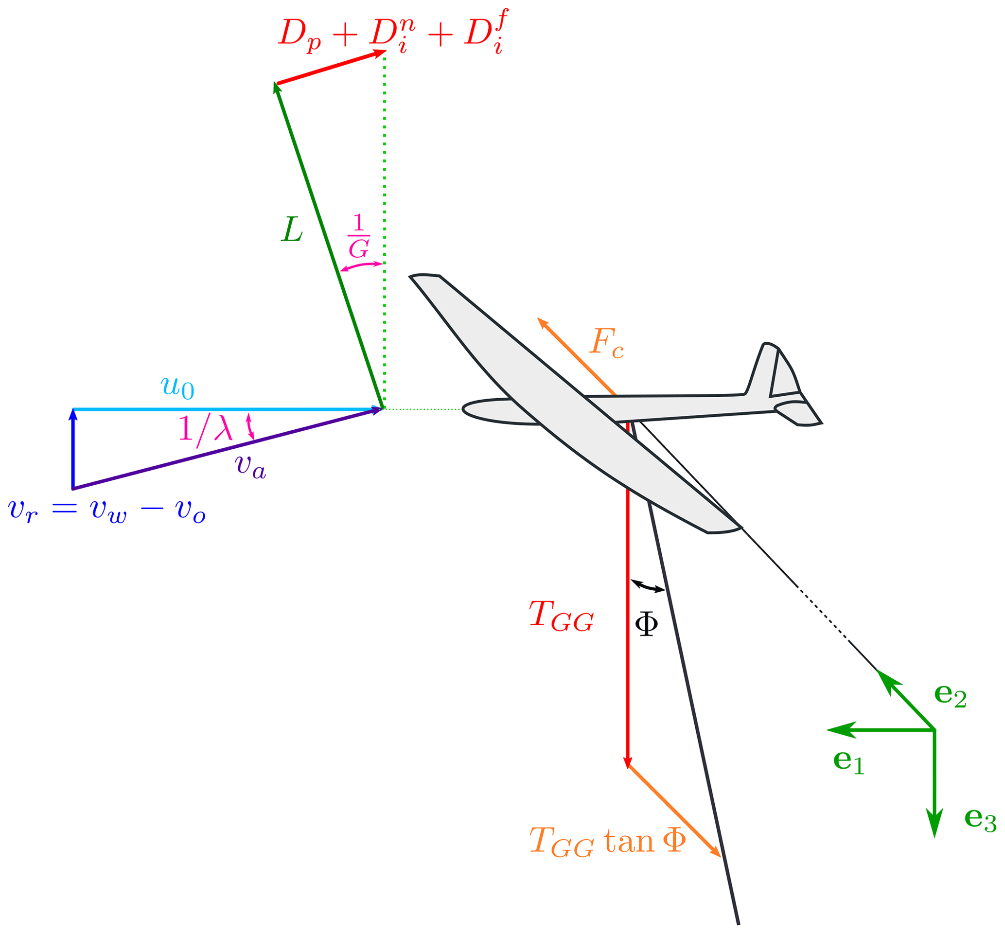
Referring to Fig. 2, the relative wind velocity is the difference between the incoming wind velocity vw and the axial component of the reel-out velocity vo. In accordance with the vortex wake model of Sect. 2, the incoming wind is assumed constant, and the gravity is neglected, which makes the problem axial symmetric. In steady state, the forces acting on the AWES need to be in equilibrium. For the force balance along e1 to be null, the lift combines with the drag such that the force balance along the AWES longitudinal direction e1 is null. As a result, the wing speed ratio λ is equal to the glide ratio G. For the force balance along e3 to be null, the axial component of the tensile force acting on the tether TGG needs to be equal to the total aerodynamic force,
where ρ is the air density, A is the wing area and is the apparent velocity. For high glide ratios G (and thus high wing speed ratio λ), TGG can then be approximated with
where is the reel-out factor (measuring how much the tether is reeled out along the axial direction with respect to the wind speed).
Looking at the force balance along e2, it exits one opening angle Φ of the cone swept by the tether over the loop for which the lift is entirely used for power production (Trevisi et al., 2020a). This condition is obtained when the centrifugal force Fc is equal to the radial component of the tether force TGGtan Φ. Writing the centrifugal force as , with m being the AWES mass plus one-third of the tether mass (Trevisi et al., 2020a) and R0=Ltsin Φ, the equation for the opening angle Φ is
The reel-out power is then the product between the axial component of the tether force TGG and the axial component of the reel-out velocity vo=vwγo:
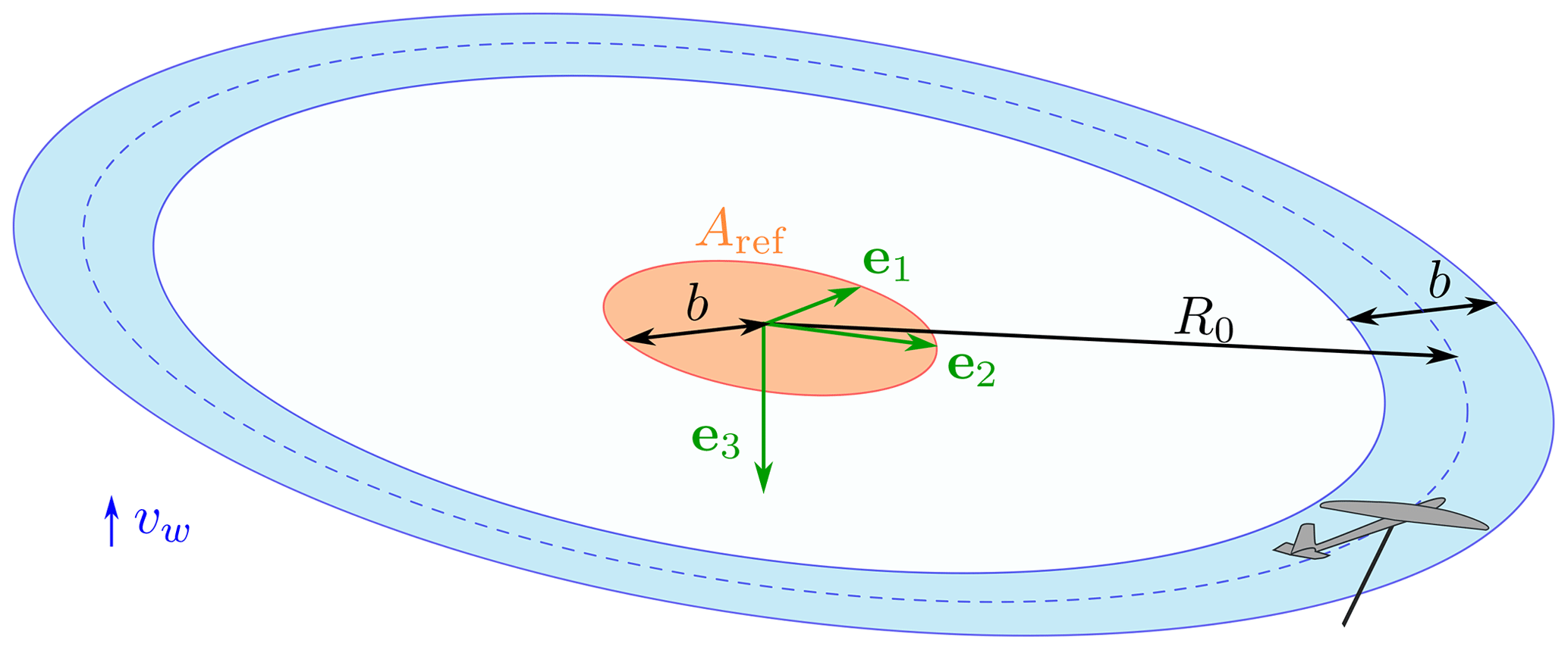
Taking inspiration from conventional wind energy, a power coefficient can be obtained by normalizing the power PGG with a reference kinetic energy per unit time, i.e., the power of the flow passing through a reference area Aref. In the case of conventional wind turbines, this reference kinetic energy rate is commonly defined by the far-field flow velocity value and the rotor disk area. In AWE, one could take as a reference area the annulus swept by the AWES Aref=2πR0b (blue area in Fig. 3). However, this area varies at different wind speeds as the turning radius R0 depends on the AWES lift coefficient CL through Eq. (11). A second option would be to take as reference area the AWES wing area Aref=A. This would lead to the power harvesting factor (PHF), as defined by Diehl (2013) and Kheiri et al. (2019). The power harvesting factor enables the comparison of AWESs for a given wing area. A third option, used in this work, is to take Aref as the area of a disk with a radius equal to the AWES wingspan Aref=πb2 (orange area in Fig. 3). With this definition, Aref is a fixed value defined by the geometry of the system, as for conventional wind turbines, and enables the comparison of AWESs for a given wingspan. Moreover, Aref is the reference area of an equivalent conventional turbine characterized by the same lifting body span (i.e., the wind turbine blades and the AWES wing have the same span). The advantage of this power coefficient definition compared to the first two is evident when analyzing the results in Sect. 5. Adopting the latter reference area definition and writing the wing area as , the power coefficient is
With the same approach, a thrust coefficient can be defined as
Since the system drag coefficient is not influenced by the relative wind speed at the AWES, CP,GG is maximized when the term γo(1−γo)2 is maximized, which is . The maximum power coefficient is then
Note that this power coefficient does not model the reel-in phase and the power losses due to the potential energy exchange.
In this section, the power equation of Fly-Gen AWESs, considering the wake model given in Sect. 2, is derived.
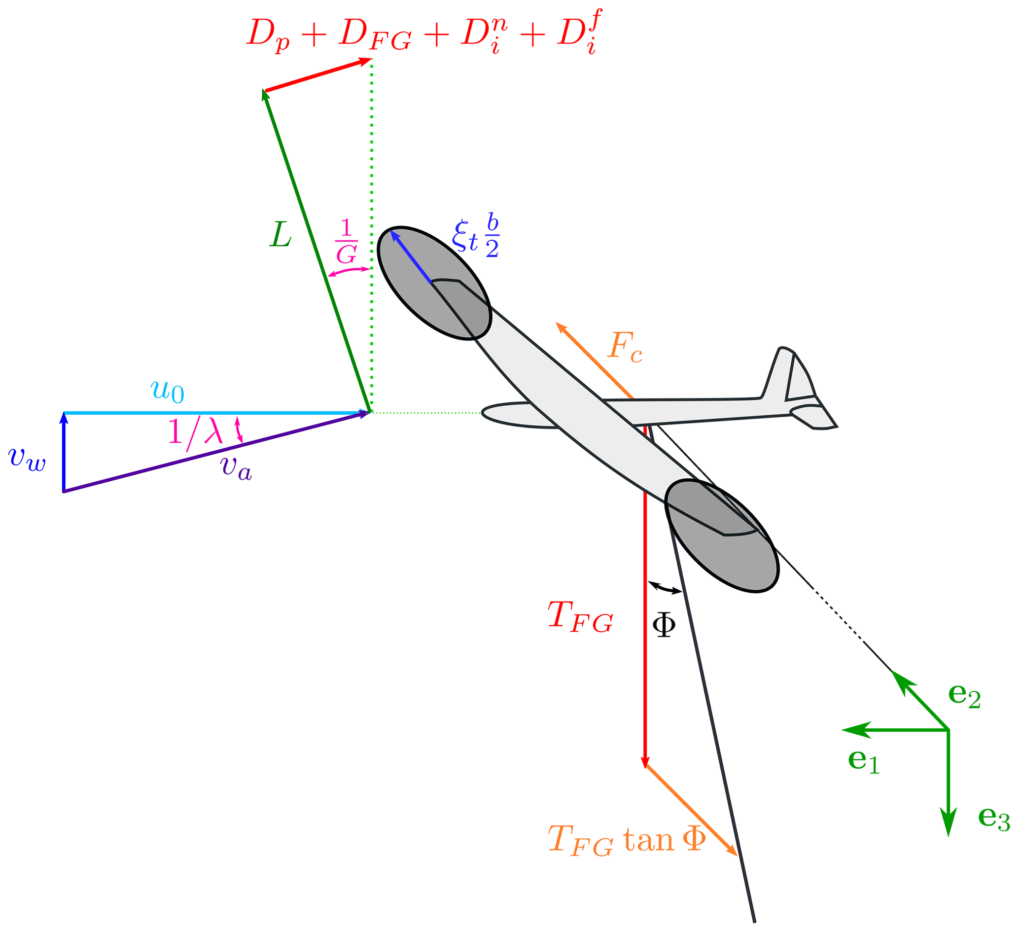
For a Fly-Gen, as no reel-out velocity is present, the relative wind speed is the actual wind speed vr=vw. The incoming wind is assumed constant, and gravity is neglected in this work such that the problem is axial symmetric. In steady state, the forces acting on the AWES need to be in equilibrium. For the force balance along e1 to be null, the lift combines with the drag such that the force balance along the AWES longitudinal direction e1 is null. As a result, the wing speed ratio λ is equal to the glide ratio G. For the force balance along e3 to be null, the axial component of the tensile force acting on the tether TFG needs to be equal to the total aerodynamic force . For high glide ratios G (and thus high wing speed ratio λ), TFG can be approximated with the aerodynamic lift L, and the apparent velocity can be approximated with the longitudinal velocity u0=G vw. TFG becomes
For the force balance along e2 to be null without contributions from the lift, Eq. (11) needs to be satisfied, as for Ground-Gen AWESs.
Assuming that the onboard turbine rotors are perpendicular to the AWES motion, the thrust force produced by the onboard wind turbines is
where CT,t is the thrust coefficient of the onboard wind turbines with respect to the wing area (and not with respect to the onboard wind turbine rotor area, as is typically done for conventional wind energy). As DFG is felt by the AWES dynamics as a drag force, CT,t should be included into the system glide ratio estimation, as in Eq. (5). CT,t can be expressed as a function of the aerodynamic drag as , where CD is the system drag. γt is then the ratio between the onboard wind turbine thrust and the aerodynamic system drag. The system glide ratio is then
The thrust power of the onboard wind turbine Pt,FG is the product between the thrust force DFG and the Fly-Gen AWES velocity u0=Gvw:
The shaft power of the onboard wind turbine PFG (i.e., the mechanical power that can be converted to electrical power) is modeled using 1D momentum theory (actuator disk). The onboard wind turbine thrust (Eq. 17) can be formulated with momentum theory:
where At is the total turbine area, and the onboard wind turbine induction at is assumed to be small. By setting Eq. (17) equal to Eq. (20), the onboard wind turbine induction is , and the shaft power is
A small value of is necessary to reduce power losses due to the onboard wind turbine induction and potential energy exchange (Trevisi et al., 2022a). The turbine radius can be expressed as a function of the wingspan as (Fig. 4). The total rotor area of the turbine is , where nt is the number of turbines, all assumed to be of the same size. To present the results in a more concise way, without losing generality, the number of turbines is assumed to be equal to two nt=2 such that .1 The shaft power can be written as
The thrust power coefficient of Fly-Gen AWES, taking the reference area as the disk with a radius equal to the AWES wingspan, is
where CD depends on γt through the far-wake induced drag (the normalized torsional parameter λ0 is a function of λ, which is a function of γt). In the case of straight wakes (κ0=0), the optimal value of γt which maximizes the thrust power Pt,FG is (Loyd, 1980). Using this value, the thrust power coefficient is
which coincides with the maximum power coefficient of Ground-Gen AWESs when κ0=0: (Eq. 15). For κ0 larger than 0, the far wake contributes in different ways for the two generation types, leading to different power coefficients. This is shown in Sect. 5.
The shaft power coefficient includes power losses due to the onboard wind turbine induction:
Note that this power coefficient does not model power losses due to the potential energy exchange. See Trevisi et al. (2022a) for more details on these losses.
The thrust coefficient can be defined as
In this section, Ground-Gen and Fly-Gen AWES performances are compared according to the mathematical models introduced in the previous sections. As a given design can be operated at lift coefficients different from the lift coefficient the AWES is designed for, the analyses are initially performed as a function of the operational AWES lift coefficient CL. Later in the section, the design lift coefficient is considered the varying parameter to study its influence on the geometrical design and on the performances.
The first study concerns Fly-Gen AWESs and addresses the effects of the size of the onboard wind turbines on their aerodynamic induction at (see parameter ξt in Fig. 4). A case with AR=20, and the inverse turning ratio is considered in this section, corresponding to the example in Trevisi et al. (2023b). Figure 5 shows the optimal values of the onboard wind turbine thrust factor γt on the left axis and the efficiency due to the onboard wind turbine induction 1−at on the right axis, as a function of the lift coefficient, for three different ξt parameters. The optimal values of γt are found by solving the optimization problem
where h is defined in Eq. (8). For low lift coefficients, the optimal value of γt is close to 0.5. For increasing lift coefficients, γt rises slightly above 0.5 to decrease the glide ratio G (Eq. 18) and consequently the normalized torsional parameter λ0. Decreasing λ0 increases the vortex ring axial distance h0 (Eq. 3) and thus decreases the induction due to the far wake. As expected, smaller onboard turbines decrease the efficiency 1−at. For the following analyses in this section, it is assumed ξt=0.15, as this is considered a reasonable value.
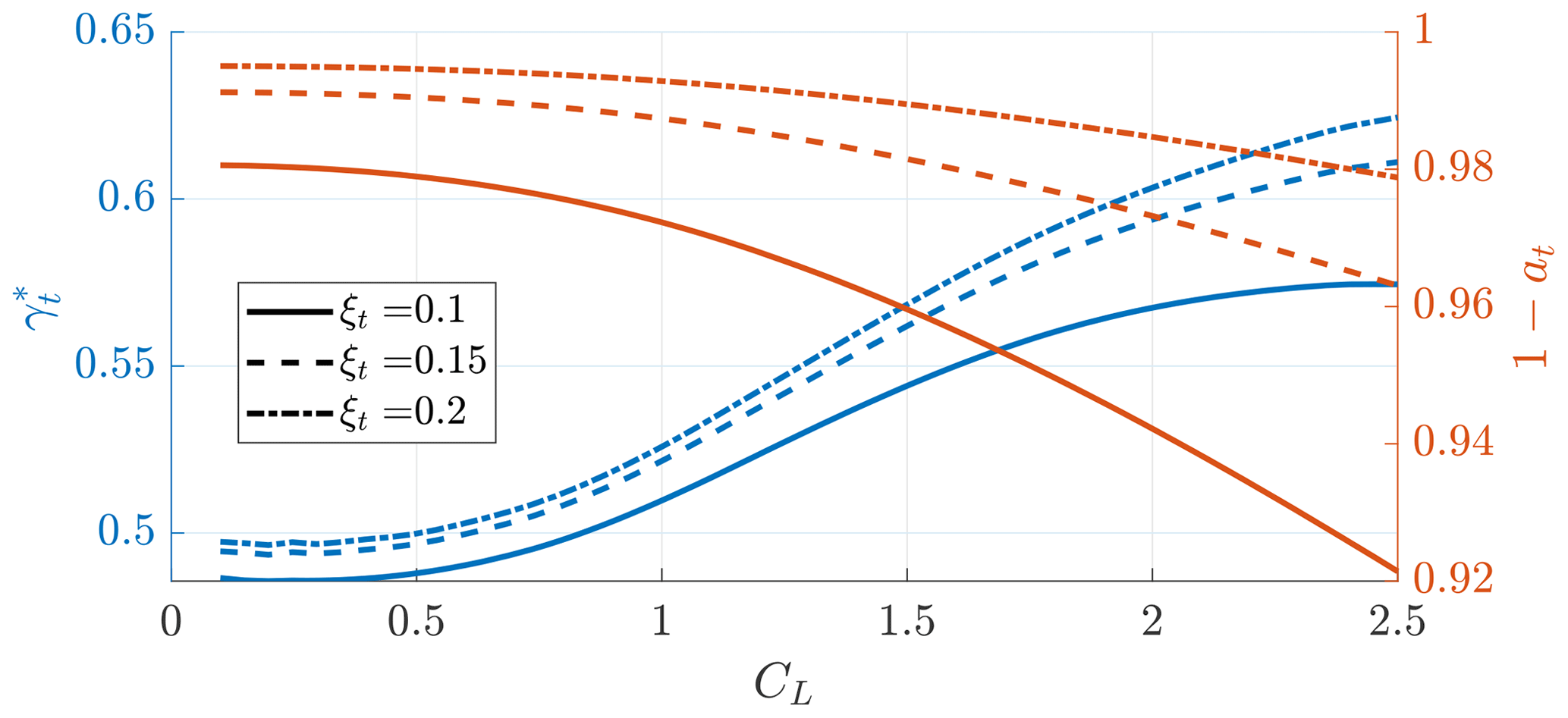
Figure 5Optimal value of γt (blue – left axis) and efficiency due to onboard wind turbine induction (red – right axis) for different onboard wind turbine non-dimensional radii ξt as a function of the operational AWES lift coefficient. Case AR=20, κ0=0.15 and .
The second study investigates the difference in the normalized torsional parameter and glide ratio for Ground-Gen and Fly-Gen AWESs, shown in Fig. 6. Ground-Gen values are found by considering the reel-out factor and numerically solving Eq. (8). Fly-Gen values are found by solving the optimization problem (27). As the onboard wind turbine thrust acts as a drag force on Fly-Gen AWESs, they have a lower glide ratio compared to Ground-Gen. The normalized torsional parameter λ0 informs with respect to the pitch of the helicoidal aerodynamic wake and is linked to the wind speed ratio λ, which is equal to the glide ratio λ=G. A larger λ0 means a lower pitch h0 of the helicoidal aerodynamic wake, according to Eq. (3), and thus higher induced velocities due to the far wake. This is due to the reel-out velocity of Ground-Gen AWESs, which makes them fly closer to their own wake.
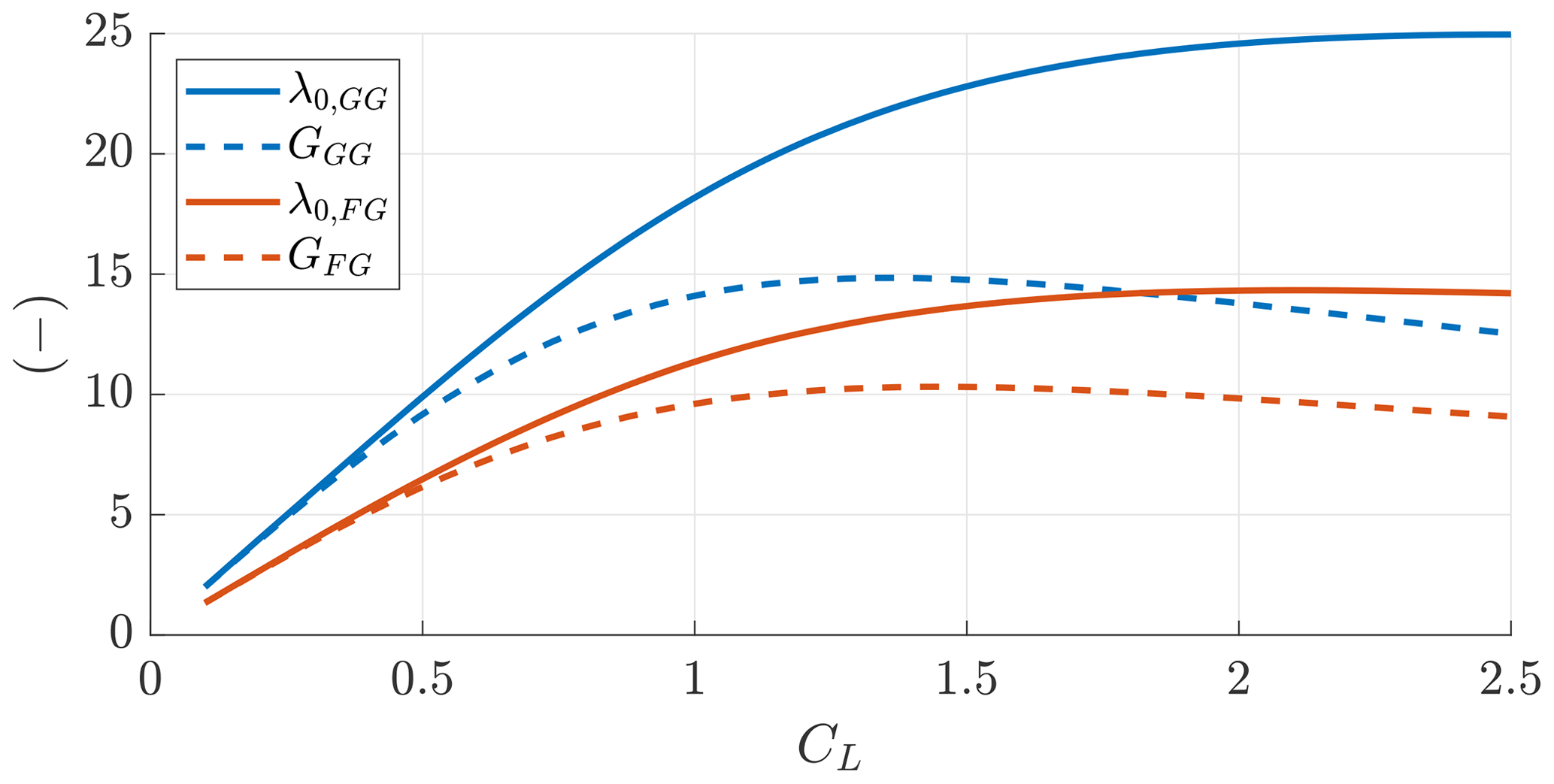
Figure 6Normalized torsional parameter for a Ground-Gen and Fly-Gen AWES (solid blue and red lines respectively) and the glide ratio (dashed blue and red lines respectively) as a function of the operational lift coefficient. Case AR=20, κ0=0.15, and ξt=0.15.
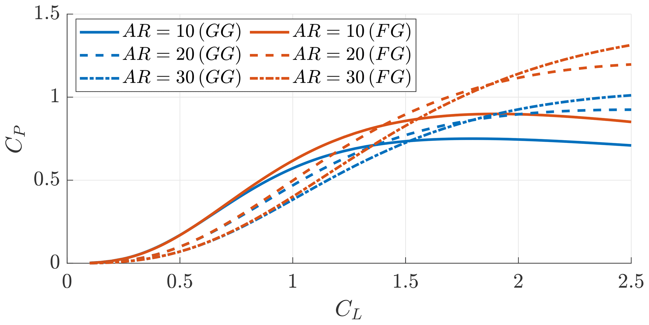
Figure 7Power coefficients of Ground-Gen (blue lines) and Fly-Gen (red lines) AWESs as a function of the operational lift coefficient. Case κ0=0.15, , ξt=0.15 and three different AR values.
The third study compares the power coefficient of Ground-Gen and Fly-Gen AWESs for varying aspect ratios as a function of the operational lift coefficient and investigates which aspect ratio is optimal as a function of the design lift coefficient. Figure 7 shows the optimal power coefficients for Ground-Gen and Fly-Gen AWESs as a function of the operational lift coefficient for three different aspect ratios. Fly-Gen can extract more aerodynamic power compared to the Ground-Gen AWESs with the same geometry due to the far-wake pitch. This is in accordance with the findings from Kheiri et al. (2019). Indeed, as discussed when analyzing Fig. 6, Ground-Gen AWESs fly closer to their own wake due to reel-out velocity. Higher power coefficients can be obtained with higher aspect ratios at high operational lift coefficients. In this comparison, if the aspect ratio is doubled (e.g., from 10 to 20), the wing area is halved, as the inverse turning ratio κ0 (and thus b) is kept constant. To find which aspect ratio maximizes the power coefficient, one could set the partial derivative of CP with respect to the aspect ratio to 0. The resultant aspect ratio can then be considered in the conceptual design phase of an AWES project. To get to an analytical solution, the wake is considered straight (κ0=0). The maximum power coefficient for Ground-Gen AWESs (, Eq. 15) and the thrust power coefficient with for Fly-Gen (Eq. 24) are considered. Under these assumptions, the power coefficients of Ground-Gen and Fly-Gen AWESs coincide: (Eqs. 15 and 24). The partial derivative of CP with respect to the aspect ratio is
where is the lift coefficient chosen for the design of the aspect ratio, and
assuming that the parasite drag coefficient CD,p is not dependent on the aspect ratio.
After a few steps, the condition which maximizes CP is found when the induced drag coefficient is equal to the parasite drag coefficient, , which results in
where the symbol ⊗ indicates an optimal quantity obtained with analytical models. This aspect ratio answers the following question: given a wingspan, which aspect ratio maximizes power? Note that this derivation would not have been possible if the power coefficient was defined as the power harvesting factor (PHF) (taking as reference area Aref in Eqs. (13) and (23) the wing area A). Indeed, by taking , one looks for the aspect ratio which answers the following question: given a wing area, which aspect ratio maximize power? The solution to this question is an infinite aspect ratio. This highlights one of the benefits of using a reference area for the power coefficient proportional to the wingspan and not to the wing area.
The aspect ratios which maximize the CP for Ground-Gen and Fly-Gen AWESs, considering the wake structure and the onboard wind turbine induction, can be found by solving two optimization problems.
For Ground-Gen AWESs, the optimal values of γo and AR can be found by solving the optimization problem
where h is defined in Eq. (8), and it does not depend on γo. Its optimal value is always (Eq. 15).
For Fly-Gen AWESs, the optimal values of γt and AR can be found by solving the optimization problem
In Fig. 8, the analytical solution (Eq. 30) is compared with the optimization problem results. For κ0=0, the optimal AR for Ground-Gen is equal to the analytical expression, while for Fly-Gen it is slightly different because Eq. (30) is derived by considering thrust power and not shaft power. By increasing κ0, the optimal aspect ratio increases by a relatively small value compared to the analytical solution. Equation (30) can then be used in design and optimization studies as an educated initial guess for the wing aspect ratio, when the design wing lift coefficient and the parasite drag coefficient are known.
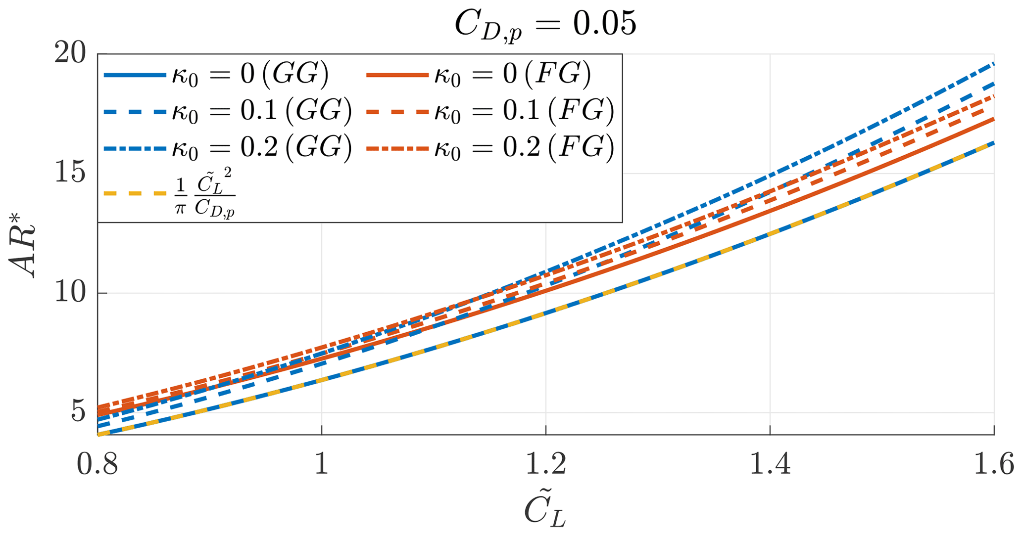
Figure 8Optimal aspect ratio found analytically (AR⊗) and numerically (AR*) for Ground-Gen (blue lines) and Fly-Gen (red lines) for different κ0 values as a function of the design lift coefficient . Case and ξt=0.15.
In the last study of this section, the optimal power coefficient is studied as a function of the design lift coefficient for different inverse turning ratios. By using the analytical expression for the optimal AR (Eq. 30), obtained with , in Eqs. (15) and (24) (the thrust power coefficient for Fly-Gen is considered), the maximum power coefficient with a straight wake (κ0=0) is
This power coefficient physically represents the upper bound of the power production of an AWES flying in a circular path with an infinite radius, for a given design lift coefficient and parasite drag coefficient.
Following a similar procedure, a corresponding thrust coefficient is found by inserting the analytical expression for AR⊗ into Eq. (14) with and Eq. (26) with and considering κ0=0:
Figure 9 shows the optimal power coefficients, found by solving the optimization problems (31) and (32), as a function of for different κ0 values. The maximum power coefficient, considering straight wakes, of Fly-Gen AWESs is slightly lower than the analytical maximum power coefficient (Eq. 33) and because of the power losses due to onboard wind turbine induction. For increasing κ0, the maximum power coefficient decreases. As noted when analyzing Fig. 7, Fly-Gen AWESs have a higher power generation potential compared to Ground-Gen AWESs. The power coefficients of Ground-Gen (Eq. 13) and Fly-Gen (Eq. 25) are defined by taking the disk with a radius equal to the AWES wingspan as the reference area. Considering this reference area, the AWES power coefficient can take values higher than the Betz limit and the unity without violating any physical laws. Note that the power coefficient for Ground-Gen AWESs neglects the reel-in phase and the losses due to the potential energy exchange, while the power coefficient for Fly-Gen AWESs neglects the losses due to the potential energy exchange.
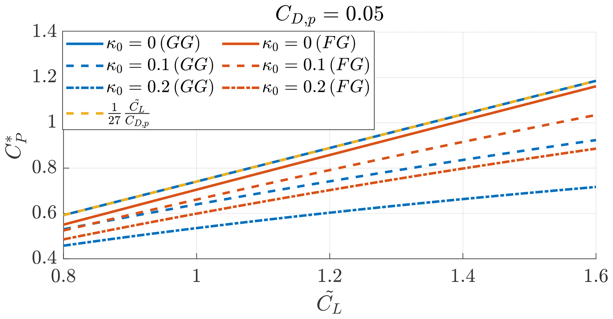
Figure 9Aerodynamic power coefficients, as a function of the design lift coefficient , of Ground-Gen (blue lines) and Fly-Gen (red lines) AWESs and the maximum aerodynamic power coefficient (dashed yellow line). Case , ξt=0.15, the optimal aspect ratio AR*, and the optimal coefficients and .
In this section, Ground-Gen and Fly-Gen AWESs, with the same geometry, are compared. Fly-Gen AWESs have smaller glide ratios because the onboard wind turbine thrust is included in the drag estimation. Ground-Gen AWESs fly closer to their own wake due to the reel-out velocity; they thus have a larger normalized torsional parameter λ0. Fly-Gen AWESs can then harvest more power because of the wake structure. If the aspect ratio is increased, higher power coefficients can be obtained at high operational lift coefficients. The aspect ratio which maximizes the power coefficient is finite, and the analytical solution for straight wakes is . This analytical expression can be used in the preliminary design phase of an AWES project. By considering the optimal aspect ratio, the maximum thrust and power coefficients can be found, and their analytical expressions for straight wakes can be obtained. The expression for the maximum power coefficient can be used to estimate the upper bound of an AWES power production.
In this section, two Ground-Gen AWESs and one Fly-Gen AWES from the literature are analyzed based on the mathematical models introduced in this paper. In particular, the inverse turning ratio, the glide ratio, the contribution from the far-wake induced drag coefficient and the power coefficients are analyzed.
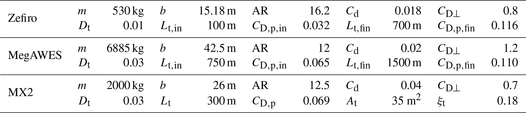
In Table 1, the parameters describing the selected AWESs are given. The flight mechanics of Zefiro, an ultralight glider, when used as Ground-Gen AWESs is studied by Trevisi et al. (2021) and its design is studied by Trevisi et al. (2022b). MegAWES refers to the AWES introduced by Eijkelhof and Schmehl (2022). As Zefiro and MegAWES operate at different tether lengths during the reel-out phase, they are studied at the initial and final tether lengths by solving Eq. (8). The Makani MX2 (Tucker, 2020) is a Fly-Gen AWES, and it is studied by solving the optimization problem (27). A detailed analysis of its power losses due to potential energy exchange is carried out by Trevisi et al. (2022a).
Table 1 Reference values for the examples. Zefiro (Trevisi et al., 2022b) and MegAWES (Eijkelhof and Schmehl, 2022) are Ground-Gen AWESs, and the Makani MX2 is a Fly-Gen AWES (Tucker, 2020).
In Fig. 10, the inverse turning ratios are shown as a function of the lift coefficient. The optimal opening angle Φ, computed with Eq. (11), is used to find the turning radius R0, and thus . The inverse turning ratio is larger for Ground-Gen AWESs at the initial tether length. Note that the vortex model assumes a fully developed wake, and this assumption does not hold when analyzing the first few loops of the reel-out phase.
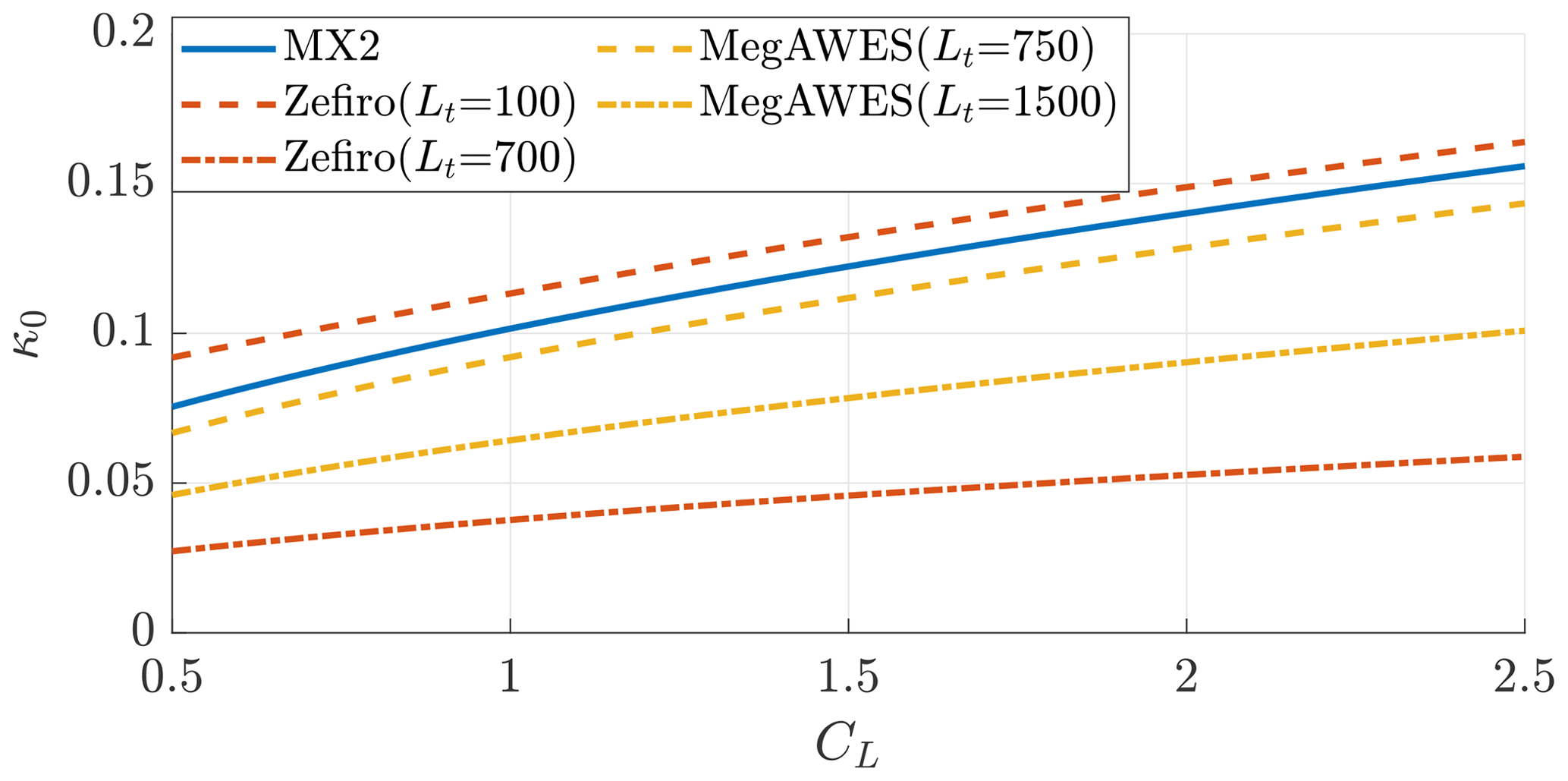
Figure 10Inverse turning ratios as a function of the lift coefficient for the examples (Table 1). The Ground-Gen AWES κ0 is shown at the initial and final tether length.
In Fig. 11, the glide ratio is shown. As noted when comparing Ground-Gen and Fly-Gen AWESs in Sect. 5, the Fly-Gen MX2 has a lower glide ratio as the onboard wind turbine thrust is included in the drag estimation. The tether length largely influences the glide ratio. At low tether lengths, the glide ratio is higher because the tether drag contributes with a small share to the parasite drag coefficient CD,p.
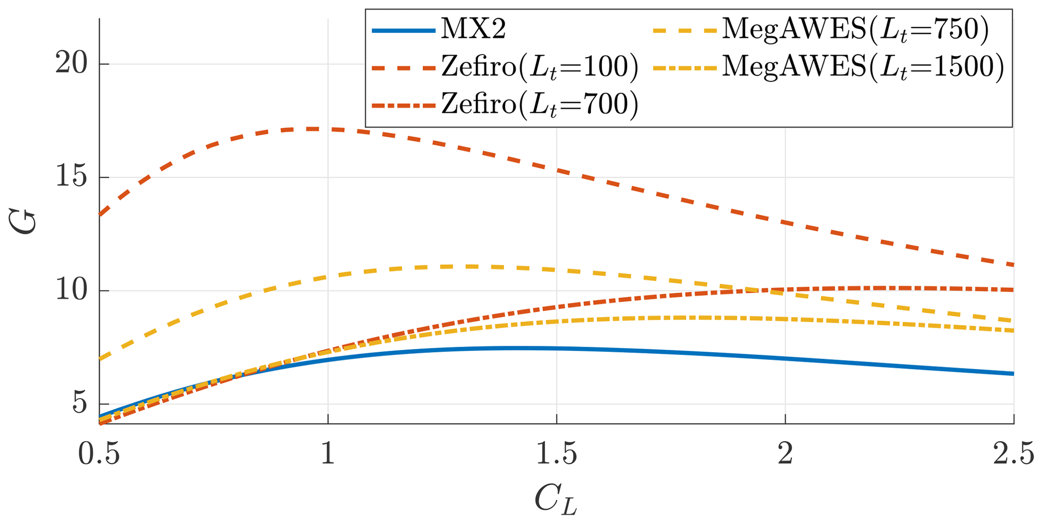
Figure 11Glide ratios as a function of the lift coefficient for the examples (Table 1). Ground-Gen AWESs G is shown at initial and final tether length.
In Fig. 12, the ratio of induced drag due to the far wake to the total induced drag is shown. For Ground-Gen AWESs, the far-wake contribution is high at low tether lengths and decreases during the reel-out as the inverse turning ratio (Fig. 10) and the glide ratio (Fig. 11) decrease.
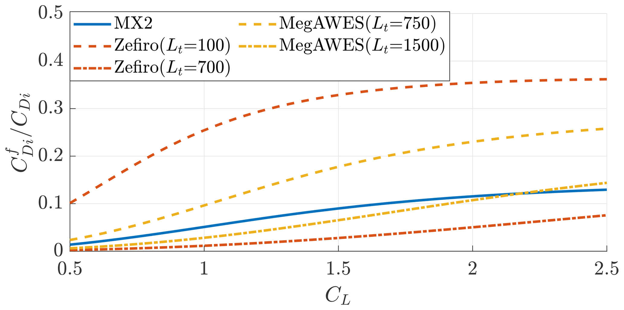
Figure 12Ratio of the induced drag due to the far wake and the total induced drag as a function of the lift coefficient for the examples (Table 1). The Ground-Gen AWES values are shown at the initial and final tether lengths.
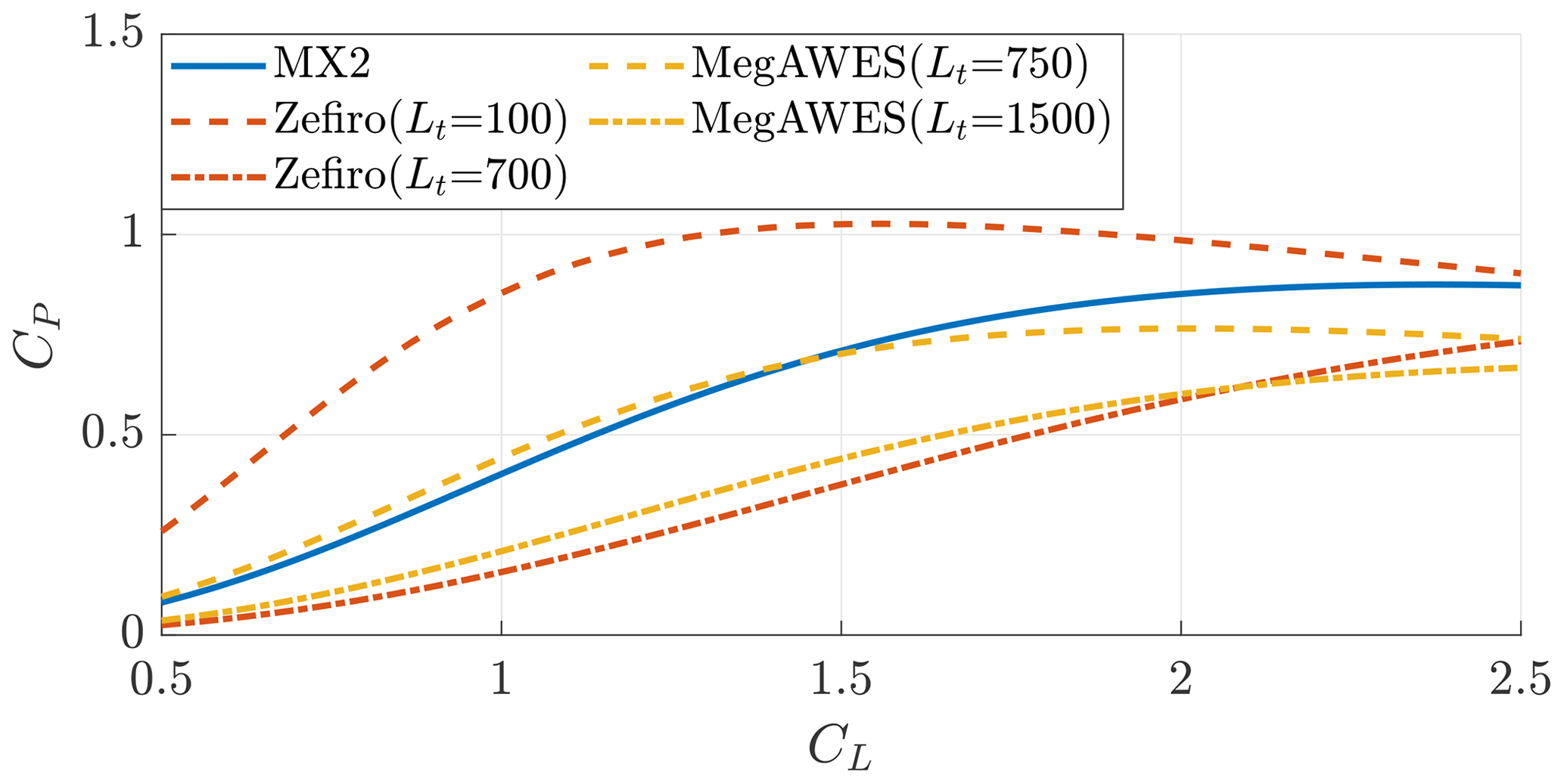
Finally, the optimal power coefficients are shown in Fig. 13. Ground-Gen AWESs at low tether lengths can achieve higher optimal CP values. At the initial tether length, Zefiro maximizes power with a lift coefficient of approximately CL≈1.5 and MegAWES of approximately CL≈2. This indicates that, from aerodynamic considerations, operating the AWES at different lift coefficients could be optimal at different tether lengths. The MX2 maximizes power with a lift coefficient of approximately CL≈2.3. This shows that higher lift coefficients could not be required for a design similar to the MX2.
In this work, the aerodynamic wake model developed by Trevisi et al. (2023b) is used to refine the power equations of Ground-Gen and Fly-Gen AWESs. The aerodynamic model assumes steady crosswind circular trajectories and a non-expanding helicoidal vortex wake. The main assumptions and equations of the wake model are reported in Sect. 2. The power equations of Ground-Gen and Fly-Gen AWESs are refined by accounting for the aerodynamic wake in the induced drag coefficient estimation. In this way, the effects of changing the aspect ratio, turning radius, lift coefficient, parasite drag coefficient, dimension of the onboard turbines (for Fly-Gen AWESs) and control quantities (reel-out velocity for Ground-Gen AWESs and onboard wind turbine thrust for Fly-Gen AWESs) on the aerodynamic performances and power production can be intuitively understood. The optimal onboard wind turbine thrust of Fly-Gen is slightly influenced by the wake structure, while the optimal reel-out velocity of Ground-Gen is not.
A novel power coefficient is defined by normalizing the aerodynamic power with the wind power passing through a disk with a radius equal to the AWES wingspan, enabling the comparison of different designs for a given wingspan. The aspect ratio which maximizes this power coefficient is found to be finite. Considering an infinite turning radius, the optimal aspect ratio is , where is the design lift coefficient and CD,p the parasite drag coefficient, and the maximum power coefficient is . For decreasing turning radii, the optimal aspect ratios increase slightly, and the maximum power coefficients decrease with respect to the analytical expressions.
By comparing power coefficients, Ground-Gen AWESs are found to have a lower power generation potential with respect to Fly-Gen AWESs with the same geometry because they fly closer to their own wake due to the reel-out velocity of the tether. Three AWESs of different sizes from the literature are studied. Two Ground-Gen AWESs are analyzed at the initial and final tether lengths of the reel-out phase, revealing that higher power coefficients can be obtained at shorter tether lengths because of the reduced tether drag. A Fly-Gen AWES is analyzed, showing that power is maximized at a finite lift coefficient.
| Latin symbols | |
| A | Wing area |
| AR | Wing aspect ratio |
| b | Wingspan |
| Cd | Wing profile drag coefficient |
| CD | System drag coefficient |
| CD,c | Drag coefficient modeling all AWES components |
| excluding the main wing and the tether | |
| CDi | Induced drag coefficient |
| Induced drag coefficient due to the far wake | |
| Induced drag coefficient due to the near wake | |
| CD,p | Parasite drag coefficient |
| CD⟂ | Drag coefficient of the tether section |
| CD,t | Equivalent tether drag coefficient |
| CL | Wing lift coefficient |
| Design wing lift coefficient | |
| CP | Power coefficient |
| CPt | Thrust power coefficient (for Fly-Gen AWESs) |
| CT | Thrust coefficient |
| CT,t | Onboard wind turbine thrust coefficient |
| with respect to the AWES wing area | |
| Dt | Tether diameter |
| G | Glide ratio |
| h0 | Helicoidal wake pitch |
| Lt | Tether length |
| m | AWES mass plus one-third of the tether mass |
| R0 | Mid-span turning radius |
| u0 | Longitudinal velocity |
| va | Apparent wind speed |
| vr | Relative wind speed |
| vw | Wind speed |
| Greek symbols | |
| γo | : reel-out factor |
| γt | : onboard wind turbine thrust factor |
| κ0 | : inverse turning ratio |
| λ | : wing speed ratio |
| λ0 | : normalized torsional parameter of the |
| helicoidal wake | |
| Φ | Opening angle of the cone swept by the tether |
| during one loop | |
| ρ | Air density |
| Symbols | |
| * | Optimal quantity |
| ⊗ | Optimal quantity found analytically |
All figures and the MATLAB code developed to generate them can be retrieved via https://doi.org/10.5281/zenodo.8210953 (Trevisi et al., 2023a). The figures can be opened with MATLAB or other open-source programming languages (e.g., Python, Octave).
FT conceptualized and developed the research methods, produced the results, and wrote the draft version of the paper. AC and CEDR supervised the research, supported the methodology conceptualization and reviewed the paper.
At least one of the (co-)authors is a member of the editorial board of Wind Energy Science. The peer-review process was guided by an independent editor, and the authors also have no other competing interests to declare.
Publisher’s note: Copernicus Publications remains neutral with regard to jurisdictional claims made in the text, published maps, institutional affiliations, or any other geographical representation in this paper. While Copernicus Publications makes every effort to include appropriate place names, the final responsibility lies with the authors.
This research has been partially supported by the MERIDIONAL project, which receives funding from the European Union’s Horizon 2020 program (grant agreement no. 101084216).
This paper was edited by Roland Schmehl and reviewed by two anonymous referees.
Anderson, J.: Fundamentals of Aerodynamics, McGraw-Hill Education, sixth edn., http://lccn.loc.gov/2015040997 (last access: 11 May 2023), 2017. a
Argatov, I. and Silvennoinen, R.: Efficiency of Traction Power Conversion Based on Crosswind Motion, in: Airborne Wind Energy, edited by: Ahrens, U., Diehl, M., and Schmehl, R., 65–79, Springer Berlin Heidelberg, Berlin, Heidelberg, https://doi.org/10.1007/978-3-642-39965-7_4, 2013. a
Bauer, F., Kennel, R. M., Hackl, C. M., Campagnolo, F., Patt, M., and Schmehl, R.: Drag power kite with very high lift coefficient, Renew. Energ., 118, 290–305, https://doi.org/10.1016/j.renene.2017.10.073, 2018. a
De Lellis, M., Reginatto, R., Saraiva, R., and Trofino, A.: The Betz limit applied to Airborne Wind Energy, Renew. Energ., 127, 32–40, https://doi.org/10.1016/j.renene.2018.04.034, 2018. a
Diehl, M.: Airborne Wind Energy: Basic Concepts and Physical Foundations, in: Airborne Wind Energy, edited by: Ahrens, U., Diehl, M., and Schmehl, R., 3–22, Springer Berlin Heidelberg, Berlin, Heidelberg, https://doi.org/10.1007/978-3-642-39965-7_1, 2013. a, b
Eijkelhof, D. and Schmehl, R.: Six-degrees-of-freedom simulation model for future multi-megawatt airborne wind energy systems, Renew. Energ., 196, 137–150, https://doi.org/10.1016/j.renene.2022.06.094, 2022. a, b
Gaunaa, M., Forsting, A. M., and Trevisi, F.: An engineering model for the induction of crosswind kite power systems, J. Phys. Conf. Ser., 1618, 032010, https://doi.org/10.1088/1742-6596/1618/3/032010, 2020. a, b, c
Kheiri, M., Bourgault, F., Saberi Nasrabad, V., and Victor, S.: On the aerodynamic performance of crosswind kite power systems, J. Wind. Eng. Ind. Aerod., 181, 1–13, https://doi.org/10.1016/j.jweia.2018.08.006, 2018. a
Kheiri, M., Saberi Nasrabad, V., and Bourgault, F.: A new perspective on the aerodynamic performance and power limit of crosswind kite systems, J. Wind. Eng. Ind. Aerod., 190, 190–199, https://doi.org/10.1016/j.jweia.2019.04.010, 2019. a, b, c
Leuthold, R., Crawford, C., Gros, S., and Diehl, M.: Engineering Wake Induction Model For Axisymmetric Multi-Kite Systems, J. Phys. Conf. Ser., 1256, 012009, https://doi.org/10.1088/1742-6596/1256/1/012009, 2019. a
Loyd, M.: Crossswind Kite Power, J. Energy, 4, 106–111, 1980. a, b
Luchsinger, R. H.: Pumping Cycle Kite Power, in: Airborne Wind Energy, edited by: Ahrens, U., Diehl, M., and Schmehl, R., 47–64, Springer Berlin Heidelberg, Berlin, Heidelberg, https://doi.org/10.1007/978-3-642-39965-7_3, 2013. a
Marten, D., Lennie, M., Pechlivanoglou, G., Nayeri, C. N., and Paschereit, C. O.: Implementation, Optimization, and Validation of a Nonlinear Lifting Line-Free Vortex Wake Module Within the Wind Turbine Simulation Code qblade, J. Eng. Gas Turb. Power, 138, 072601, https://doi.org/10.1115/1.4031872, 2015. a
Schmehl, R., Noom, M., and van der Vlugt, R.: Traction Power Generation with Tethered Wings, in: Airborne Wind Energy, edited by: Ahrens, U., Diehl, M., and Schmehl, R., 23–45, Springer Berlin Heidelberg, Berlin, Heidelberg, https://doi.org/10.1007/978-3-642-39965-7_2, 2013. a
Trevisi, F., Gaunaa, M., and Mcwilliam, M.: The Influence of Tether Sag on Airborne Wind Energy Generation., J. Phys. Conf. Ser., 1618, 032006, https://doi.org/10.1088/1742-6596/1618/3/032006, 2020a. a, b, c, d
Trevisi, F., Gaunaa, M., and Mcwilliam, M.: Unified engineering models for the performance and cost of Ground-Gen and Fly-Gen crosswind Airborne Wind Energy Systems, Renew. Energ., 162, 893–907, https://doi.org/10.1016/j.renene.2020.07.129, 2020b. a
Trevisi, F., Croce, A., and Riboldi, C. E. D.: Flight Stability of Rigid Wing Airborne Wind Energy Systems, Energies, 14, 7704, https://doi.org/10.3390/en14227704, 2021. a, b
Trevisi, F., Castro-Fernández, I., Pasquinelli, G., Riboldi, C. E. D., and Croce, A.: Flight trajectory optimization of Fly-Gen airborne wind energy systems through a harmonic balance method, Wind Energ. Sci., 7, 2039–2058, https://doi.org/10.5194/wes-7-2039-2022, 2022a. a, b, c, d
Trevisi, F., Riboldi, C. E. D., and Croce, A.: Sensitivity analysis of a Ground-Gen Airborne Wind Energy System design., J. Phys. Conf. Ser., 2265, 042067, https://doi.org/10.1088/1742-6596/2265/4/042067, 2022b. a, b
Trevisi, F., Riboldi, C. E. D., and Croce, A.: Figures and code: Refining the airborne wind energy systems power equations with a vortex wake model, Zenodo, https://doi.org/10.5281/zenodo.8210953, 2023a. a
Trevisi, F., Riboldi, C. E. D., and Croce, A.: Vortex model of the aerodynamic wake of airborne wind energy systems, Wind Energ. Sci., 8, 999–1016, https://doi.org/10.5194/wes-8-999-2023, 2023b. a, b, c, d, e, f, g
Tucker, N.: Airborne Wind Turbine Performance: Key Lessons From More Than a Decade of Flying Kites, in: The Energy Kite Part I., edited by: Echeverri, P., Fricke, T., Homsy, G., and Tucker, N., 93–224, Makani Technologies LLC, https://x.company/projects/makani/# (last access: 11 May 2023), 2020. a, b
Vander Lind, D.: Analysis and Flight Test Validation of High Performance AirborneWind Turbines, in: Airborne Wind Energy, edited by: Ahrens, U., Diehl, M., and Schmehl, R., 473–490, Springer Berlin Heidelberg, Berlin, Heidelberg, https://doi.org/10.1007/978-3-642-39965-7_28, 2013. a
Vermillion, C., Cobb, M., Fagiano, L., Leuthold, R., Diehl, M., Smith, R. S., Wood, T. A., Rapp, S., Schmehl, R., Olinger, D., and Demetriou, M.: Electricity in the air: Insights from two decades of advanced control research and experimental flight testing of airborne wind energy systems, Annu. Rev. Control, 52, 330–357, https://doi.org/10.1016/j.arcontrol.2021.03.002, 2021. a
The limiting case with ξt=1 can be obtained with the two turbines placed at the wing tips. This corresponds to the largest value of At possible, considering nt≥2.
- Abstract
- Introduction
- Vortex wake model
- Reel-out power equation of Ground-Gen AWESs
- Shaft power equation of Fly-Gen AWESs
- Comparison between Ground-Gen and Fly-Gen AWESs
- Numerical examples
- Conclusions
- Appendix A: Nomenclature
- Code and data availability
- Author contributions
- Competing interests
- Disclaimer
- Financial support
- Review statement
- References