the Creative Commons Attribution 4.0 License.
the Creative Commons Attribution 4.0 License.
 | 23 Jun 2020
Top-level rotor optimisations based on actuator disc theory
Peter Jamieson
Ahead of the elaborate rotor optimisation modelling that would support detailed design, it is shown that significant insight and new design directions can be indicated with simple, high-level analyses based on actuator disc theory. The basic equations derived from actuator disc theory for rotor power, axial thrust and out-of-plane bending moment in any given wind condition involve essentially only the rotor radius, R, and the axial induction factor, a. Radius, bending moment or thrust may be constrained or fixed, with quite different rotor optimisations resulting in each case. The case of fixed radius or rotor diameter leads to conventional rotor design and the long-established result that power is maximised with an axial induction factor, . When the out-of-plane bending moment is constrained to a fixed value with axial induction variable in value (but constant radially) and when rotor radius is also variable, an optimum axial induction of 1∕5 is determined. This leads to a rotor that is expanded in diameter 11.6 %, gaining 7.6 % in power and with thrust reduced by 10 %. This is the low-induction rotor which has been investigated by Chaviaropoulos and Voutsinas (2013). However, with an optimum radially varying distribution of axial induction, the same 7.6 % power gain can be obtained with only 6.7 % expansion in rotor diameter. When without constraint on bending moment, the thrust is constrained to a fixed value, and the power is maximised as a→0, which for finite power extraction would require R→∞. This result is relevant when secondary rotors are used for power extraction from a primary rotor. To avoid too much loss of the source power available from the primary rotor, the secondary rotors must operate at very low induction factors whilst avoiding too high a tip speed or an excessive rotor diameter. Some general design issues of secondary rotors are explored. It is suggested that they may have the most practical potential for large vertical axis turbines avoiding the severe penalties on drivetrain cost and weight implicit in the usual method of power extraction from a central shaft.
- Article
(1285 KB) - Full-text XML
-
Supplement
(201 KB) - BibTeX
- EndNote


Two quite different innovative rotor concepts have been considered previously. These are the low-induction rotor and the secondary rotor.
A low-induction rotor in optimal operation is designed to operate with lower values of axial induction than 1∕3, the ideal value according to the according to basic actuator disc (AD) theory to maximise power at a fixed chosen diameter. The primary motivation for the low-induction concept is to lower the cost of energy in scenarios where sacrificing some power in reducing design induction values leads to relatively more significant load reductions that are of overall economic benefit to the design. Discussion of the low-induction concept appears in Johnson (2019), where Christopher L. Kelly of Sandia National Laboratories, in an unpublished presentation at the Wind Energy Science Conference of 2017, had noted that the first low-induction design with constrained blade rotor bending moment was due to Ludwig Prandtl and is reproduced in Tollmien et al. (1961). Snel (2003) observed that when the power coefficient, Cp, is stationary at its maximum value associated with an axial induction of 1∕3, the thrust coefficient, Ct, is still strongly increasing. Simple actuator disc theory determines that when . There is therefore, for a very small power penalty, a relatively large reduction in thrust, and there are associated bending moments to be gained from reducing induction levels a little below the theoretical optimum for maximum power, and independent blade manufacturers have long been aware of this. The potential benefits of yet more radical reductions in induction to around 0.2 were highlighted by Chaviaropoulos and Voutsinas (2013). Work on low-induction rotors continued in the Innwind.EU project (Chaviaropoulos et al., 2013), and structural design issues of a low-induction rotor were reviewed by Chaviaropoulos and Sieros (2014). Development of lower lift aerofoils that may suit a very large rotor (Chaviaropoulos et al., 2015) was of value in addressing the problems of stability of aerofoil characteristics at a very high Reynolds number, a topic relevant for all very large rotors, but aerofoil design requirements for low-induction rotors can be better defined following the optimisation of the spanwise distribution of induction. Low-induction designs with expanded rotor diameter continued to be explored by Chaviaropoulos et al. (2013), Bottasso et al. (2014) and Quinn et al. (2016), but again all of this work including associated cost of energy analyses was predicated on non-optimum largely constant spanwise distributions of induction. The Technical University of Denmark (DTU) 10 MW reference turbine was further developed as an International Energy Agency (IEA) reference turbine by Borlotti et al. (2019). This work involved sophisticated multi-variable numerical optimisations with complex constraints, entirely appropriate for a detailed reference turbine design, but with the result that the role of reduced induction could not be clearly seen in isolation. However the rotor diameter was regarded as a free variable, and this will be shown to be of the essence of the low-induction concept.
The secondary-rotor concept involves extracting power using a rotor generator system mounted on the blades of an otherwise conventional primary turbine. The secondary rotors operate at high speed in much-elevated relative air speeds leading to much smaller and lighter power conversion equipment than with a conventional centre-shaft-based drivetrain. This idea emerged in designs such as the space frame turbine of Watson (1988) and the airborne system of Jack (1992), where the driver was to have an ultra-lightweight wind turbine. Thus the motivation for secondary-rotor systems has always been to reduce drivetrain mass and potentially also cost. The secondary-rotor concept was considered further by St-Germain (1992) and Madsen and Rasmussen (2008). Jamieson (2011) highlighted it as a possible solution to the design challenge faced by large vertical-axis wind turbines (VAWTs), where a very low optimum speed leads to high drivetrain torque, weight and cost if the power is extracted in the most usual way from the central shaft. Leithead et al. (2019) employed secondary rotors for power take-off in an innovative X-rotor VAWT design.
This paper shows that the low-induction and secondary-rotor concepts have a common origin in basic optimisations derived from actuator disc theory. As already discussed, these design concepts are not themselves new, but their fundamental connection to elementary actuator disc theory has not previously been highlighted. More significantly, once this connection is made, it much facilitates high-level analyses that can usefully guide preliminary design. A key assumption in blade element momentum theory (BEM) is that the rotor plane may be analysed as a set of annular rings that are regarded as mutually independent. This enables AD theory to be generalised to deal with a spanwise variation of induction. AD theory and BEM are very long established, and the form of equations used here often follows Jamieson (2011).
The underlying actuator disc optimisations are now presented, followed by their application to more detailed analyses guiding top-level design of the low-induction rotor and secondary rotor respectively.
2.1 Actuator disc equations
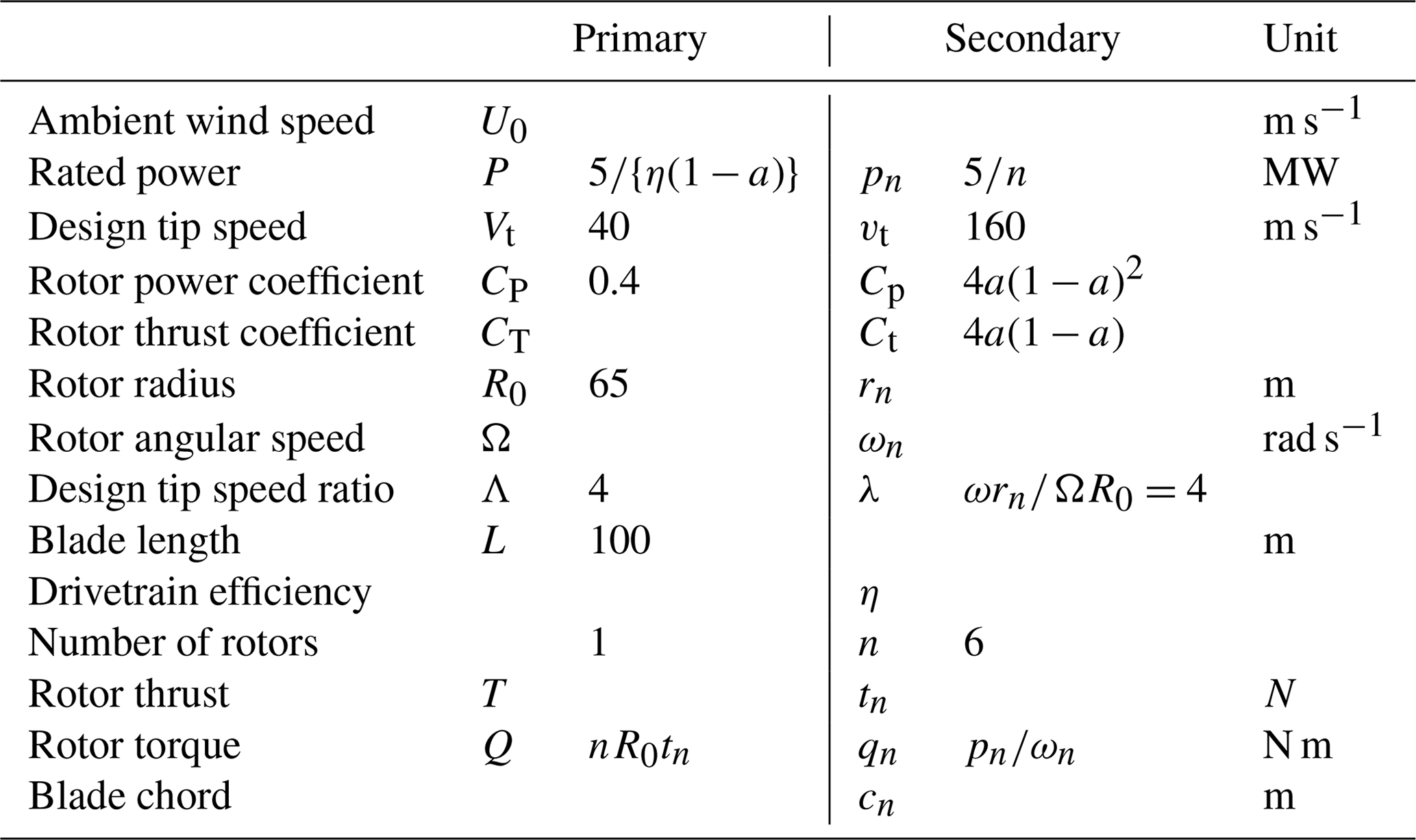
Actuator disc equations for power, thrust and out-of-plane bending moment as related to ambient wind speed, U0; air density, ρ; and rotor radius, R, are presented in Table 1. The coefficients of power and thrust, Cp and Ct, depend only on the axial induction factor, a, and are in widespread use. A companion out-of-plane bending moment coefficient, Cm, is also defined as in Jamieson (2011). The standard assumption of blade element momentum theories is that each annular ring of the actuator disc can be treated as independent. Thus, when the axial induction varies radially, rotor area-averaged values of the coefficients may be defined as in the right column of Table 1.
Table 1Basic actuator disc equations for power, thrust and out-of-plane bending moment.

Three distinct optimisations are now considered with the objective in each case of maximising power:
- a.
the rotor radius is fixed and axial induction is to be determined;
- b.
the out-of-plane bending moment is fixed but rotor radius and axial induction are variable;
- c.
the rotor thrust is fixed but rotor radius and axial induction are variable.
2.2 Optimisations with radially constant induction
The optimisations are first considered in the context of an axial induction that does not vary spanwise. Case (a) is the familiar one where, with radius R fixed and power , which is consequently maximised with . This represents conventional design and is the basis of a reference design used in subsequent comparisons. In the reference design, R=R0, P=P0, T=T0 and M=M0, where the reference values, P0, T0 and M0 are all based on R=R0 and . In case (b), the out-of-plane blade bending moment is fixed and , which on solving for R yields
Substituting for R from Eq. (1), the power equation becomes
From Eq. (2), the power, P, now varies only with a and
Differentiating P in Eq. (3) to find a maximum leads to , and hence P is maximised at . Comparing with a standard rotor design, when and P is maximum,
As in Jamieson (2018), general trends of R, P, M and T relative to unit values of the standard rotor are presented in Fig. 1.
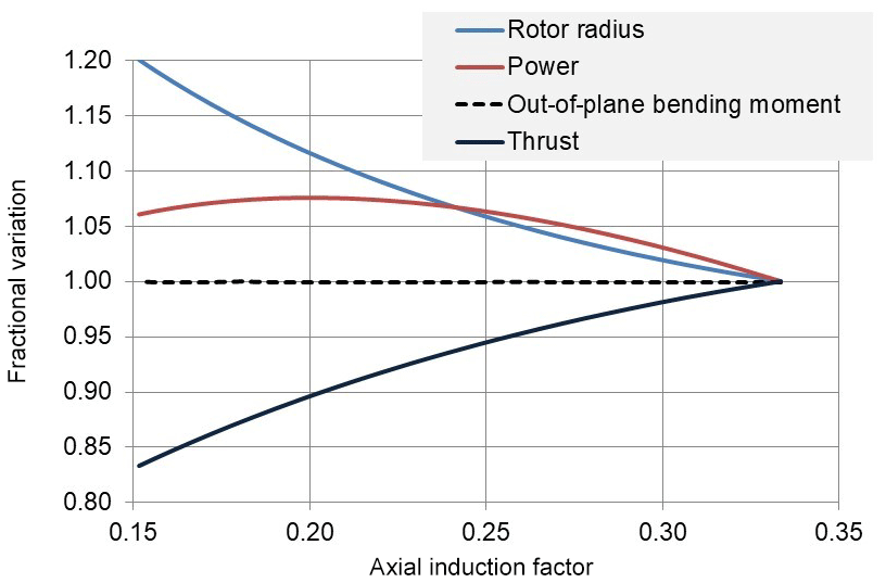
The analysis indicates that a rotor designed for an axial induction factor of 0.2 that is 11.6 % larger in diameter can operate with 7.6 % increased power and 10 % less thrust yet at the same level of blade rotor out-of-plane bending moment as the baseline design. In case (c), the thrust is maintained at a constant value, T0. Since power and is constant, it is evident that the power and is maximised as a→0. However, for the power to be finite and positive when the axial induction and hence the power coefficient are zero requires R→∞.
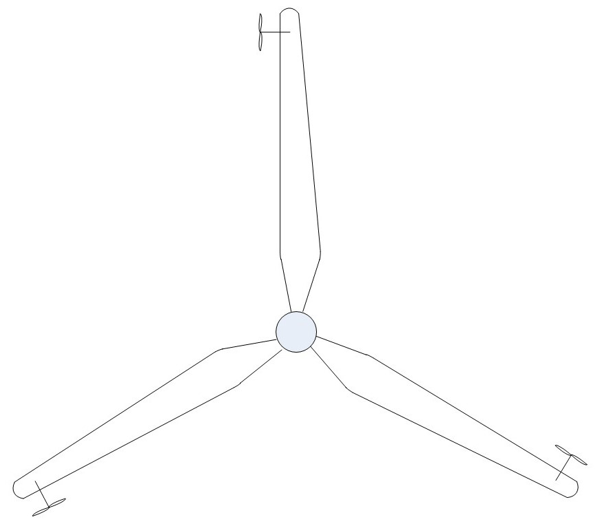
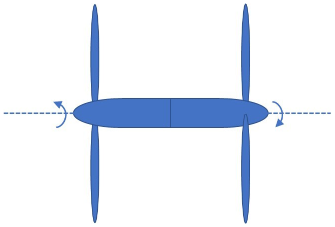
As opposed to the conventional solution of power take-off from a central shaft, additional (secondary) rotors are set on the blades or other support arms at a radial distance from the central axis of the primary rotor, thereby experiencing a high relative wind speed. The ideal optimisation at zero induction and hence infinite radius cannot be realised, but it will be shown that very low induction values are feasible without unacceptably large secondary rotors. The secondary rotor may be therefore be considered as an ultra-low-induction rotor. In the system of Fig. 2, the torque reaction to the primary rotor is provided by thrust on the secondary rotors, and a specific value of thrust on each secondary rotor is therefore required to optimise power extraction from the primary rotor. The secondary rotors are small, high-speed rotors, and the sum of design torques of all secondary rotors can be much less than the design torque associated with power take-off in the conventional way from a central shaft. This property can offer a solution to a key problem of large VAWT design where an inherently lower shaft speed than any equivalent horizontal-axis wind turbine (HAWT) puts a large premium on drivetrain torque, mass and cost.
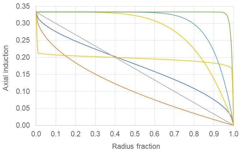
For a radially constant axial induction distribution and fixed out-of-plane bending moment, M=M0, it was established in Sect. 2 that a=0.2 maximises power, giving a 7.6 % power gain for 11.6 % radius expansion compared to conventional design. The question then arises of whether an optimised radially varying distribution of axial induction can realise greater power gains or, for example, the same 7.6 % power gain at reduced rotor expansion. Related to this is the question of what may be a suitable, efficient generalised model of the radially variable axial induction. A representation in the form is found to be versatile and highly effective. With arbitrary values of only two free variables, n and p, a wide range of distributions can be generated (Fig. 3). This even includes approximations to constant values of axial induction less than 0.333, for example, a=0.2. The curve (yellow trace) of Fig. 3 illustrates this although a much more accurate approximation than shown can be obtained. More general optimisation methods could be employed to determine optimum distributions of axial induction subject to varied constraints, but the simple approach adopted here is highly effective.
Now there can never be benefit in as the bending moment would be increased and power decreased. Also as x→0, the bending moment M→0, and so in the limit x→0, which is approaching the shaft centre, it is logical that in any design that seeks to constrain only bending moment. In the following analyses, a, n and p are all treated as free variables although, as expected, the value determined for a is usually very close to 1∕3. This tends to confirm that the optimisation, although in effect having only two free variables, n and p, is quite accurate. Polynomial representations by comparison are far inferior. A quadratic, for example, , with , would have two free variables, a2 and a1, but could only represent linear or parabolic shapes. In order to have results that are likely to be realistic for typical rotors with small finite blade numbers, a tip loss effect is introduced using the Prandtl tip loss factor, . The question of an overall maximum in power regardless of required diameter expansion is now addressed. Using the generalised forms of Cp and Cm from Table 1, the power is expressed as
Using a maximisation routine such as available in PTC Mathcad 15, an overall maximum in power P(a, n, p) is obtained, with values a=0.331, n=1.504 and p=1.125 giving an axial induction distribution as in Fig. 4. The gain in power (see Fig. 4, Pmax) is found to be 11.9 %, which is much greater than the 7.6 % for a radially constant axial induction but requiring a radial expansion of 34 %. This is too large a radial expansion to be of practical benefit considering the implications in increased tip speed or drivetrain torque. In the next analysis the radial expansion is constrained (see Fig. 4, Pcon) to a value such that the power gain is 7.6 % as for optimum constant induction. The associated axial induction distribution has parameters a=0.333, n=0.417 and p=0.136 as illustrated in Fig. 4. Note that all the distributions of Fig. 4 maintain the same constant value of out-of-plane bending moment at the shaft centre line. The striking result however is that this same power gain of 7.6 % is realised with a radius expansion of only 6.7 % (diamond marked point of Fig. 5) as opposed to the 11.6 % (triangular marked point of Fig. 5) required with a constant axial induction of 0.2.
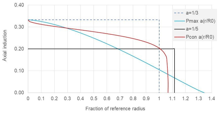
Figure 4Axial induction distributions giving rise to the same out-of-plane bending moment, M0, at rotor centre.
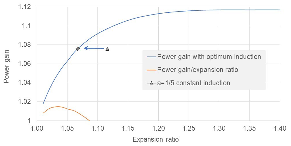
Also shown in Fig. 5 is the ratio of power gain to expansion which maximises around 3 % expansion. Above this low level, the required rotor expansion rises more rapidly than the gain in power although the most economic benefit will probably arise with power gains and rotor expansions in a 5 % to 10 % range.
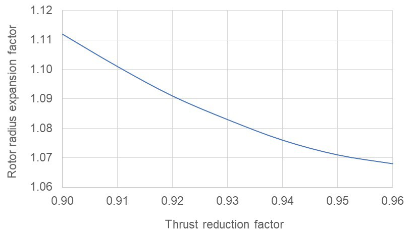
Comparing (see Fig. 4) the optimum axial induction distribution (for 7.6 % power gain) with the constant value of 0.2, it is evident that more power is being obtained over most of the span except near the blade tip. Consistent with these higher power levels, there is only a 3.5 % reduction in axial thrust for the radially variable axial distribution (Pcon in Fig. 4) as opposed to approximately 10 % reduction for constant induction at a=0.2. If cost of energy modelling suggests that there is benefit say from reduced wake impacts in a thrust reduction greater than 3.5 %, say at the same power gain of 7.6 %, with appropriate constraints on the power maximisation procedure, the necessary rotor expansion can then be related to thrust reduction as in Fig. 6.
Tip loss has no effect in comparing distributions where the axial induction is constant radially because it cancels in the power, moment and thrust ratios, provided the low-induction rotor is compared with a reference rotor having the same number of blades. It has a small effect (Fig. 7) for designs with rotor expansions below about 15 % and a more noticeable effect at large expansion ratios which however may be of little practical interest.
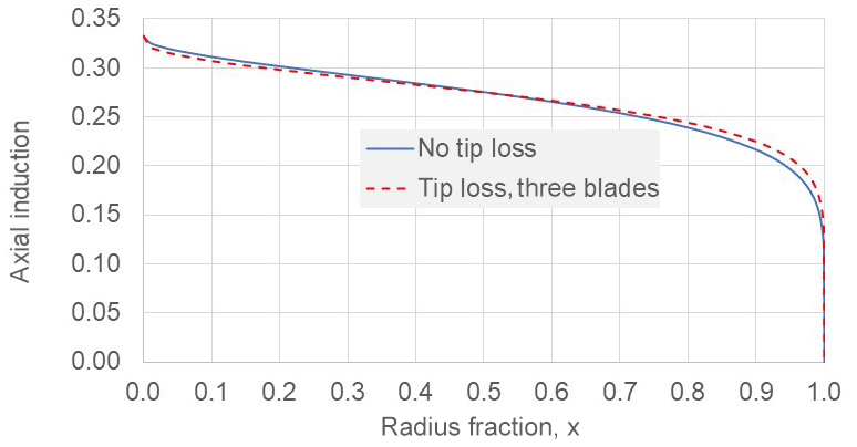
Figure 7Effect of tip loss on optimum axial induction distributions for a power gain of 7.6 %.
The distributions in Fig. 7 are very similar and that is what matters most. On account of the sensitivity of the power law relationships, the associated values of n and p will often differ considerably. For no tip loss n=0.416 and p=0.136, with tip loss n=0.295 and p=0.112. Another main issue of practical relevance is that blades are never aerodynamically active near the shaft centre line. They may become cylindrical near the root contributing only drag and connect to a hub having a conical cover or spinner. To approximate the loss of aerodynamic performance in the hub area, some of the analyses were repeated, with lower limits on integrals such as in Eq. (7) changed from 0 to 0.15. As with tip loss, effects were only very noticeable at large (impractical) expansion ratios. Figure 8 compares the results for maximum possible power gain with and without exclusion of the first 15 % of span.
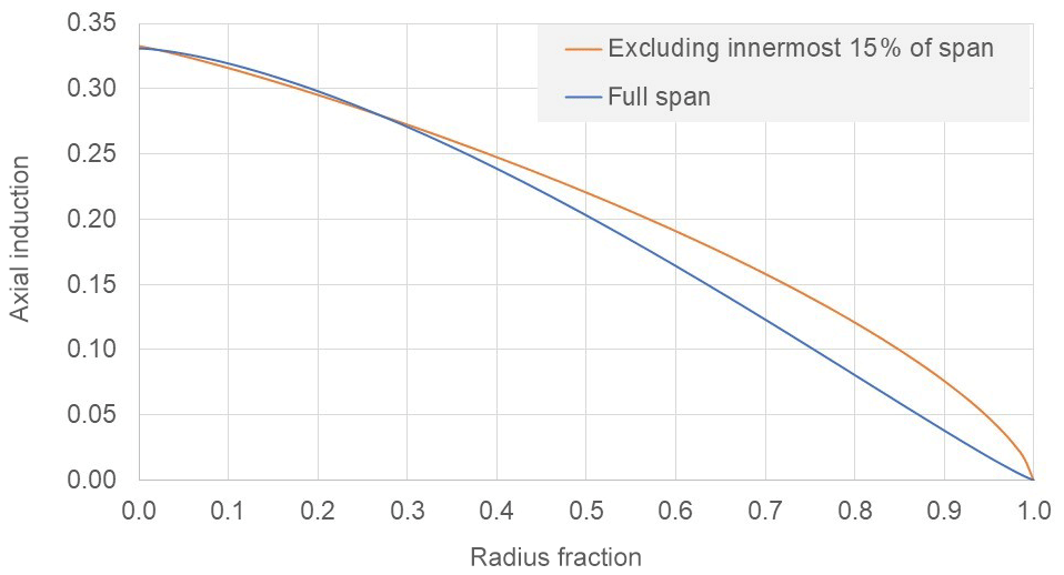
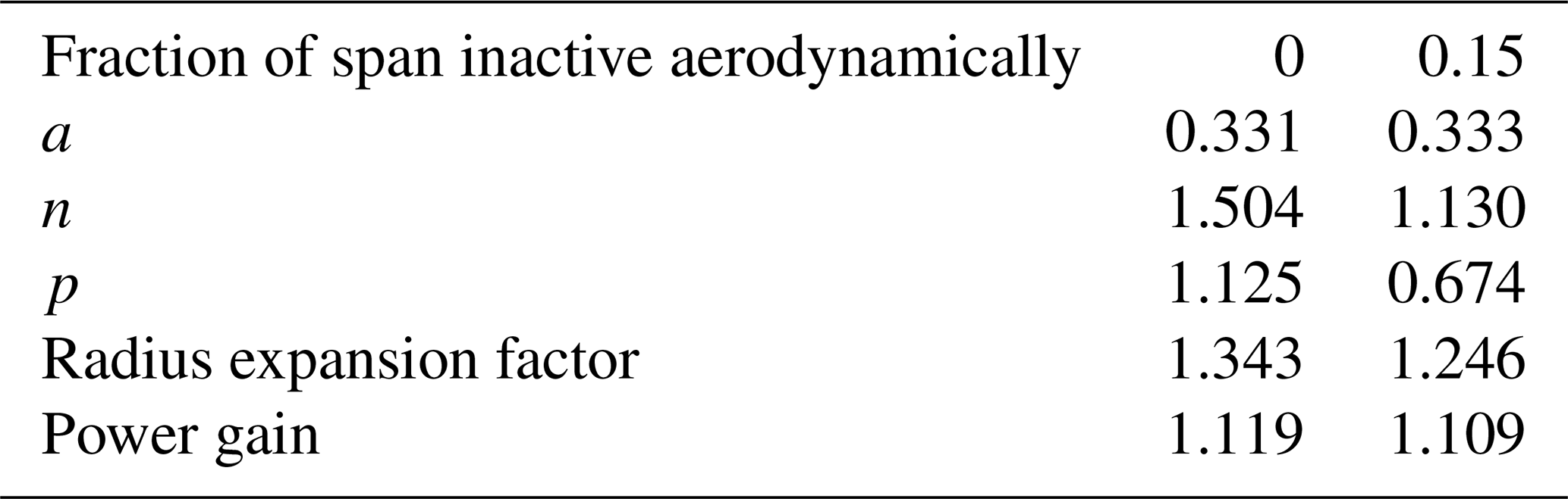
Table 2 presents data relating to axial induction distributions of Fig. 8. Although the power gains differ only ∼1 %, there is a noticeable difference in the axial induction distributions of Fig. 7 and a large difference in the rotor expansions at 34 % for the complete span being aerodynamically active and 25 % when the innermost 15 % of span is excluded. When designs in a more realistic range of parameters are considered, for example, as in Fig. 7 with power gain restricted to 7.6 %, there is no significant difference between cases with and without exclusion of the inner 15 % of the rotor.
Table 2Parameters of the distributions for maximum power gain.
4.1 Power extraction using secondary rotors
Secondary rotors near the tip of HAWT blades will experience a higher relative flow velocity and may thus be smaller in diameter than those of a VAWT of similar rated power. However the tip region of a large HAWT is subject to large deflections and a torsional stiffness that is relatively reducing with upscaling. Thus reacting the total edgewise load of a blade near the tip may pose problems for aerodynamic stability and structural stiffness. Even more problematic may be preserving alignment of secondary rotors on a pitching blade. The classic issues with VAWTs which had led to them being uncompetitive historically are (a) an intrinsically lower optimum speed leading to factors of 2 or 3 on drivetrain torque, weight and cost and (b) reduced power performance associated with intrinsically lower average lift-to-drag ratios per cycle of rotation leading to maximum power coefficients ∼0.4 when large HAWTs have power coefficients ∼0.5. Power take-off using secondary rotors may avoid the torque penalty intrinsic in a conventional VAWT design, providing a more effective drivetrain solution that may breathe new life into VAWT technology.
For these reasons the focus in the following analyses is on secondary rotors for a primary rotor of VAWT design although much of the analyses are directly relevant or easily adapted to HAWT design. The secondary rotors are always assumed to be HAWTs. In the following analyses upper case symbols refer to a primary rotor and lower case to a secondary rotor. Where there are multiple secondary rotors, the parameters of 1 of n rotors will have the subscript n. The aerodynamic torque of the primary rotor is reacted by the total thrust of the secondary rotors acting (under the present simplified assumptions) with a moment arm at the maximum radius R0 of the primary rotor. The relative wind speed incident on the secondary rotors is equal to the tip speed of the VAWT ∼40 m s−1, and as a further simplification, the ambient wind speed which is small in comparison is ignored. The power generated by the primary rotor is then
The total power, p, extracted by the secondary rotors is then
Now with the usual assumption that each annular ring of the actuator disc can be analysed independently, then Eq. (9) applies to the elemental power and thrust contributions of each annulus, and a radially varying axial induction, a(x), will have exactly the same performance as a constant induction of , the area-averaged value of a(x). For this reason only radially constant values of axial induction are considered although, in a detailed design embracing all aspects of structure and loads, there may be some benefits from radially varying axial induction. This result is of course quite different from the case of the low-induction rotor where the bending moment is constrained and radial variation of axial induction is very significant. As an example, to focus discussion of secondary-rotor design issues, parameters as in Table 3 are selected for a VAWT rated at 5 MW.
Table 3Parameters of a primary H type VAWT rotor and of secondary HAWT rotors.
4.2 Sizing of secondary rotors
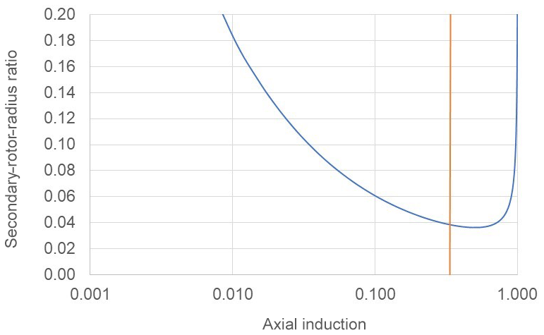
The power produced by the primary (VAWT) rotor is , and the total power extracted by n secondary rotors is . For each secondary rotor, . Hence the ratio of radius of one of n secondary rotors to that of the primary rotor can be expressed as
The ratio of secondary- to primary-rotor radius defined by Eq. (10) is shown in Fig. 9 as based on the data of Table 3. The curve is symmetrical about a=0.5 although this is not obvious as a logarithmic scale is employed in order to show more clearly the variation of rn∕R0 at very low axial induction values. The vertical line of Fig. 9 marks a=0.333. There is no interest in greater values of a, and the optimum design value for an effective system will certainly be much less than 0.333 as this would imply a sacrifice of 1∕3 of primary-rotor power. In the data of Table 3 the number of secondary rotors is chosen as six, which may be two on each of three blades or three on each of two. A value of a of 0.05 is chosen for further illustration of secondary-rotor design issues. This implies a sacrifice of 5 % of primary-rotor power, and the associated radius fraction is 0.084. Each secondary rotor then has a radius (∼5 m) that is 8.4 % of the primary-rotor radius (60 m).
4.3 Torque benefit of secondary rotors
A major issue with large VAWTs especially is a very high level of drivetrain torque. In a conventional drivetrain solution with power take-off from a central shaft, the torque, Q, of the primary rotor would drive mass and cost of the drivetrain. To assess the benefit in secondary-rotor power take-off the ratio of the sum of secondary-rotor torques to Q is now compared.
For a design with a=0.05 and parameters otherwise as in Table 3, the torque ratio has a value showing that the sum of secondary-rotor torques is th of primary-rotor torque. As a power take-off system, each secondary-rotor system comprises both bearings and generator but also an aerodynamic rotor system. The estimates of secondary-rotor diameter and torque reduction factor are realistic, provided it is accepted that at a=0.05 the fraction of available primary-rotor power extracted will be less than 95 % to an extent, depending on the effect of parasitic drag losses. For conventional large HAWTs and possibly more so for VAWTs, rotor cost is generally less than the drivetrain cost, but even at ratios 2∕50th, 3∕50th or much more, there are potentially very large savings in cost and weight of power conversion with secondary rotors. The further benefits of multiple rotors are in rn reducing as , with the torque ratio of Eq. (11) similarly reducing.
4.4 Design characteristics of secondary rotors
Does the design of the secondary rotor differ much from conventional HAWT designs considering the unusually high relative wind speed and unusually low design levels of axial induction? This is initially assessed by deriving an equation for rotor solidity. From Jamieson (2011) a non-dimensional lift distribution, with Cld as design lift coefficient (lift value at maximum lift-to-drag ratio), is determined as
In Eq. (12) the tangential induction factor, á, is determined as
Considering an annular ring of the rotor swept area of spanwise width, dr, the local solidity is the sum of planform elemental areas of B blades within the ring as a ratio of the complete swept area of the ring. Thus the local solidity at radius r is given as
and the solidity of the whole rotor is then
The right-hand side of Eq. (15) is obtained using Eq. (12) to substitute for cn in Eq. (14). A tip loss factor, F(x), appropriate to a three-bladed rotor is applied; the inner rotor region where the solidity would become infinite is omitted; and a typical aerofoil design lift coefficient, Cld, of 0.8 is assumed. An estimate of secondary-rotor solidity with a=0.05 and otherwise consistent with the values of Table 3 is determined as
The dependence of rotor solidity on aerofoil design lift coefficient is illustrated in Fig. 10. An aerofoil such as NACA 63-418 has been used on wind turbines and (with some variation according to data sources) may provide a lift-to-drag ratio of ∼125 at Cld∼1. According to Fig. 10 this may yield a solidity ∼6 % at a design axial induction ∼0.05, which is only a little higher than values of 4 %–5 % most common in large HAWT designs. Thus the secondary rotor need not differ much from conventional designs of large HAWTs in respect of solidity. Light loading from a very low design axial induction value and very high relative flow velocities have mutually compensating impacts on rotor solidity, whereas a secondary-rotor design for the usual design values of axial induction, , would have solidity ∼30 %.

The next consideration for secondary-rotor design is the range of Reynolds number, Re. For a solidity ∼0.07 as in Eq. (16), the chord at around 80 % span will be
and the associated Reynolds number is
Considering the high tip speed of the secondary rotor, using vt as the resultant velocity in the estimate of Eq. (18), and by implication neglecting the ambient wind speed, will give a good approximation. Equation (18) shows that Re values of the secondary rotor will be in a normal range for medium to large HAWTs although the rotor diameter is small ∼10 m.
Another important design consideration is the level of operational loads on the secondary rotor. Assuming a rated wind speed of Ur=11 m s−1, and a relative wind speed for the secondary rotors of 160 m s−1, then, compared to a conventional rotor of similar diameter, rotor thrusts and out-of-plane bending moments are both in the same ratio:
This is a huge increase in steady operational loading compared to conventional design. Also the steady and turbulent components of the ambient wind speed will introduce cyclic and random disturbances to secondary-rotor inflow, which may increase available power (Leithead et al., 2019) but will inevitably introduce fatigue loading. Now it is vital for the secondary rotors to minimise parasitic drag in the hub region as torque from this will absorb power from the primary rotor that cannot be recovered. It is of no benefit to have a spinner that may deflect the central flow outwards, augmenting flow over the inboard blade sections, and, equally, it is of no benefit to have ducted secondary rotors that produce any flow augmentation. This is because any augmentation contributes to added thrust (drag) on the spinner or the duct that will consume irrecoverable primary-rotor power. This suggests that the secondary-rotor system may benefit from having blades of more ideal profile than is usual near the hub centre line not because any very significant gain in secondary-rotor power can be obtained but in order to minimise drag in that area. In this scenario the blades would twist to near 90∘ out of plane, bringing the blade roots very close each other and to the axis of rotation. The large chord widths nearly parallel to the axis would be exploited for structural strength of the whole rotor, which would most probably use a lot of carbon in its construction and have titanium leading-edge erosion protection. Another idea aiming to reduce parasitic drag, perhaps too far-fetched, would be to engineer a rotor generator system with a hollow centre although there would still be issues of drag on the internal surfaces.
4.5 Secondary rotors on a common axis
Returning to actuator disc theory, the idea of twin rotors counterrotating on a common axis enabling a doubling of relative velocity at the generator air gap has been considered (Shen, 2017, and Rosenberg et al., 2014). According to simple actuator disc theory, the ideal maximum Cp with the twin rotors in series, assuming they are sufficiently apart for complete pressure recovery near the downstream rotor, increases from the Betz limit of 0.593 only to 0.64 (see Newman, 1986) or decreases to 0.32 if the swept area of both rotors is accounted for. The situation is very different for very lightly loaded secondary rotors (Fig. 11) where the downstream rotor may operate almost as efficiently as the upstream. The potential benefit of a secondary-rotor pair in a series arrangement is not only that the design torque and weight of the power train may be reduced compared to a single equivalent rotor but perhaps that a slimmer generator and hence a slimmer centre body with less parasitic drag may be realised. Any kind of multi-rotor, secondary-rotor system has obvious advantages in torque and weight reduction, but having a physical arrangement of support structure and connection to the primary rotor that minimises parasitic drag will be very important.
Based on wind tunnel tests on actuator discs represented as porous screens, Newman (1986) concluded that his theory for multiple actuator discs in series, in the particular case of two actuator discs, became inaccurate only at spacings closer than a disc radius. This gives confidence that at the very low disc loadings applicable to a pair of secondary rotors in series, spaced about a diameter apart, there should be complete pressure recovery between the rotors. A single rotor of radius 5 m could be replaced by two rotors side by side as in a multi-rotor arrangement of radius m. When the rotors are twins in series on the same axis, the radius required to have the same total thrust at an equivalent axial induction of 0.05, thereby extracting 95 % of primary-rotor power, is related to the velocity recovery approaching the downstream twin. In the analysis following, pressure recovery is assumed and the velocity approaching the downstream turbine is taken as the far wake velocity of the upstream turbine, ΩR0{1−δ}, where the velocity deficit ratio is δ and would be 2a=0.1 for a single ideal actuator disc in inviscid flow. The axial induction factors are selected in an optimisation constrained so that the twin rotors provide the specific total thrust required for primary-rotor power extraction and also extract the same total power as a single secondary rotor with the design axial induction value, a=0.05. This is accomplished as follows. The thrust, t1, on a single rotor that would be replaced by the twin system is proportional to the square of the radius, r1; the square of the relative velocity, Vt=ΩR0; and a thrust coefficient based on the axial induction, . Consider now the equivalent twin rotor system, with axial induction au on the upstream turbine, ad on the downstream turbine, relative velocity Vt on the upstream turbine and on the downstream turbine. The wake velocity deficit ratio is , where z is a factor measuring the extent of velocity recovery being 0 when, as for a single actuator disc far wake, the deficit is 2a and 1 if there is complete velocity recovery. For the twin to produce the same total thrust as the single rotor with thrust, t1, requires
In addition, if the same total power is required, then, with power being proportional to the square of the radius, to the power coefficient and to the cube of the relative velocity,
For given values of z, Eqs. (20) and (21) are solved with the additional assumption that the upstream and downstream rotors have the same radius, ru=rd, that is to be minimised.
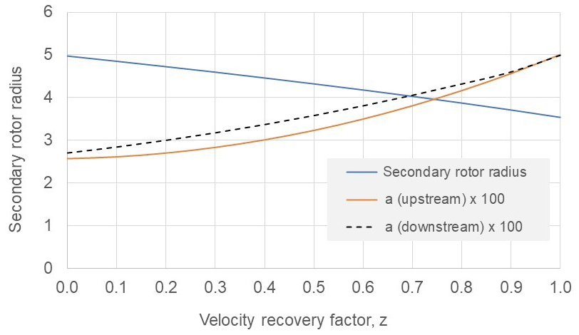
The results in Fig. 12 show the variation of secondary-rotor radius; upstream rotor induction factor, au; and downstream rotor induction factor, ad, with velocity recovery factor, z. Conventional wake models, such as assessed in a comparative study of velocity deficit by Luong et al. (2017), suggest little velocity recovery will take place between rotors 2 to 3 radii apart. However such models may be conservative and it is also difficult to gauge their applicability. The very high relative wind speed would imply a very low turbulence intensity, which would not assist velocity recovery. However, the loading on the secondary rotors is necessarily very light to avoid too much loss of primary-rotor power, and the weak wake may be skewed by centrifugal force. Quite close spacings ∼1 radius may be beneficial because of the interaction of the rotating wake which is not accounted for in any simple actuator disc modelling. A considerable amount of research into various counterrotating rotor systems has taken place since Newman (1986). Tests on a small 6 kW contra-rotating rotor discussed in Shen et al. (2017) indicated that, at the relative high loadings of conventional turbines, 30 % more power (as opposed to 8 % on the basis of an ideal Cp of 0.593 rising to 0.64) can be obtained. Numerical modelling (also Shen et al., 2017) of a counterrotating pair of Nordtank 500 kW wind turbines using the EllipSys3D code developed at the Technical University of Denmark (DTU) with reference to a particular site predicted 43.5 % more energy than for a single turbine. None of the existing literature considers the very light loadings appropriate to a pair of secondary rotors, but experiments and computational fluid dynamics (CFD; Koehuan et al., 2017) analyses generally provide encouragement that performance in real flow will exceed, sometimes greatly exceed, the performance predicted by simple actuator disc inviscid flow models. Even with little velocity recovery where the required diameter of the twin rotors approaches that of a single equivalent rotor, there may be still be net advantage from lighter blade loading, lower generator torque and reduced generator diameter with associated reduced centre body drag. The velocity recovery that may occur is evidently speculative and may only be better assessed by CFD modelling of a specific design arrangement.
Three quite distinct design directions have emerged from optimisations relating to basic loads predicted by actuator disc theory. These are (a) conventional design with rotor radius predetermined, which has been used as a reference; (b) the low-induction rotor arising from constraint on out-of-plane bending moment; and (c) the secondary-rotor concept arising from constraint on rotor thrust loading.
In comparison to conventional design, the design challenges in realising a low-induction rotor are not radically new. The present work highlights that the power gain in relation to required rotor expansion (a cost) and thrust reduction (a benefit for turbine loads and wind farm wake impacts) is sensitive to the radial distribution of axial induction and discusses optimisation around these factors. In particular it is shown that the same power gain of 7.6 % with an optimum radially constant axial induction of 0.2 that required a rotor expansion of 11.6 % can be achieved with an expansion of only 6.7 % when the axial induction varies radially and is optimised. The modelling developed here enables the definition of a space of all self-consistent combinations of power gain, rotor expansion and thrust reduction with each associated axial induction distribution. This could enable a preliminary determination of an overall optimum axial induction distribution using a combined wind turbine and wind farm cost of energy model.
An expanded rotor of standard design could be operated at low induction using pitch control, thereby restricting the steady-state blade root bending moment, but this would not be satisfactory. It is vital to contain all loads of the expanded rotor, steady state, dynamic and loads when idling in extreme wind conditions by limiting the lift and drag of the rotor to the levels of the non-expanded reference rotor. This calls for lower lift aerofoils or reduced solidity or both. There is much less of a design challenge in the low-induction rotor with a radially varying optimised axial induction distribution (Fig. 4) as compared to the constant induction of 0.2. The required rotor expansion is much less, and the progressive reduction of axial induction towards the blade tip is sympathetic to blade structural design with a natural taper in strength and solidity from rotor to tip. The graded reduction in spanwise axial induction is also much more favourable than a global reduction to 0.2 for limiting tip deflection to maintain acceptable tower clearance without having undue added cost in stiffening the blade.
Overall the results suggest there may be great value in treating the axial induction distribution and rotor diameter as free variables in a basic system optimisation for the lowest cost of energy where direct power gains, rotor loading and reduced wake effects from thrust reduction can all be traded in the design optimisation.
Secondary rotors have not been used on an operational wind turbine although a design is now being developed (Leithead et al., 2019). The main aim in using secondary rotors is to have a drivetrain with much reduced design torque compared to the usual transmission system based on power take-off from a central shaft. That can certainly be achieved, with torque reduction of 1 to 2 orders of magnitude being possible depending on specific design choices. Although the design of secondary rotors is much more demanding than that of conventional rotors of the same diameter, the design torque reduction is so great that it seems certain that substantial savings in drivetrain cost can be realised. The focus of the secondary-rotor design exploration is on VAWTs as the primary rotor rather than HAWTs because it solves a key problem with VAWTs of relatively low shaft speed leading to high drivetrain torque and expensive drivetrains, whereas, as applied to HAWT design, it could introduce major problems for primary-rotor blade design. It emerges that the radial distribution of axial induction is not critically important for secondary-rotor design as all distributions with the same area-averaged axial induction will lead to the same size of secondary rotor. The high relative wind speed compensates for relatively small rotor diameter and very low design axial induction in a way that for primary rotors in the multi-megawatt range maintains a Reynolds number ∼106 and suggests a solidity only a little higher than that typical of large HAWTs is required. However with secondary rotors, very high tip speeds are desirable to limit drivetrain torque and to limit the overall scale of the rotor and generator system. Also steady-state operational loads are exceptionally high in relation to rotor diameter. Having multiple secondary rotors (more than one per blade) has the usual benefits of multi-rotors (Jamieson, 2011) in reducing net torque, weight and cost of secondary-rotor systems, but, as was mentioned, it is particularly important with secondary rotors to minimise losses from parasitic drag or degradation of primary blade performance depending on their physical mounting arrangement. The idea of realising multi-rotors as a twin set in series on a common axis looks promising considering the very low axial induction levels required of secondary rotors to avoid wasting primary-rotor power. Whether this is a particularly good idea cannot be resolved without evaluating specific design arrangements and developing a greater understanding of the flow field around the twin secondary-rotor system.
The preliminary evaluation of the X-rotor VAWT design (Leithead et al., 2019) suggests that use of secondary rotors will lead to more competitive VAWT designs. Another innovative VAWT design, the DeepWind VAWT of Paulsen et al. (2015), has major savings through integration of the rotor blade shaft and support structure into a single element. On the other hand, substantial challenges remain for the design and maintenance of the underwater electrical generating system. Could an adapted variation of this design with modular secondary rotors that can form a more economical power train to be accessed and maintained above sea level be advantageous?
In summary, three quite different rotor optimisations are shown to arise naturally from long-established actuator disc equations and can usefully guide high-level design of the innovative rotor systems described as the low-induction rotor and the secondary rotor.
No data sets were used in this article.
The supplement related to this article is available online at: https://doi.org/10.5194/wes-5-807-2020-supplement.
The author declares that he has no conflict of interest.
This article is part of the special issue “Wind Energy Science Conference 2019”. It is a result of the Wind Energy Science Conference 2019, Cork, Ireland, 17–20 June 2019.
The author acknowledges the support of the Centre for Doctoral Training in Wind and Marine Energy of the University of Strathclyde, Glasgow.
This paper was edited by Katherine Dykes and reviewed by two anonymous referees.
Bortolotti, P., Tarres, H. C., Dykes, K., Merz, K., Sethuraman, L., Verelst, D., and Zahl, F.: IEA Wind Task 37 on Systems Engineering in Wind Energy, WP2.1 Reference Wind Turbines, available at: https://www.osti.gov/biblio/1529216/ (last access: 12 June 2020), 2019.
Bottasso, C. L., Croce, A., and Sartori, L.: Free-form design of low induction rotors, in: Sandia Wind Turbine Blade Workshop, Albuquerque, New Mexico, USA, August 2014.
Chaviaropoulos, P. K. and Sieros, G.: Design of low induction rotors for use in large offshore wind farms, in: EWEA Conf., 10–13 March 2014, Barcelona, 2014.
Chaviaropoulos, P. K. and Voutsinas S. G.: Moving towards larger rotors – is that a good idea?, in: EWEA Conf., 4–7 February 2013, Vienna, 2013
Chaviaropoulos, T., Sieros, G., Irisarri, A., Martinez, A., Munduate, X., Grasso, F., Ceyhan, O., Madsen, H. A., Bergami, L., Rasmussen, F., and Zahle, F.: Innwind.EU, WP2. New aerodynamics rotor concepts specifically for very large offshore wind turbines, Deliverable 2.11, edited by: Madsen, H. A., Bergami, L., and Rasmussen, F., European Commission, http://www.innwind.eu/publications (last access: 12 June 2020), 2013.
Chaviaropoulos, P. K., Sieros, G., Prospathopoulos, J., Diakakis, K., and Voutsinas, S.: Design and CFD-Based Performance Verification of a Family of Low-Lift Airfoils, EWEA Conf., Paris, 2015.
Jack, C.: Free rotor, patent WO/1992/020917, November 1992.
Jamieson, P.: Innovation in wind turbine design, 1st Edn., Wiley and Sons Ltd., UK, 2011.
Jamieson, P.: Innovation in wind turbine design, 2nd Edn., Wiley and Sons Ltd., UK, 2018.
Johnson, N., Bortolotti, P., Dykes, K., Barter, G., Moriarty, P., Carron, S., Wendt, F., Veers, P., Paquette, J., Kelly, C., and Ennis, B.: Investigation of Innovative Concepts for the Big Adaptive Rotor Project, Technical Report NREL/TP-5000-73605, avalable at: https://www.nrel.gov/docs/fy19osti/73605.pdf (last access: 12 June 2020), 2019.
Koehuan, V. A., Sugiyono, and Kamal, S.: Investigation of counter-rotating wind turbine performance using computational fluid dynamics simulation, IOP Conf. Ser.: Mater. Sci. Eng., 267, 012034, https://doi.org/10.1088/1757-899X/267/1/012034, 2017.
Leithead, W., Camciuc, A., Kazemi Ameri, A., and Carroll, J.: The X-rotor wind turbine concept, in: Deepwind Conf., 16–18 January 2019, Trondheim, 2019.
Luong, N. G., Maeda, T., Vu, M. P., Nguyen, B. K., Ho, B. N., and Bui, T. T.: Comparative study of velocity deficit calculation methods for a wind farm in Vietnam, IOSR J. Eng., 7, 2250–3021, 2017.
Madsen, H. A. and Rasmussen, F.: Wind turbine having secondary rotors, European Patent Specification EP 1390615 B1, April 2008.
Newman, B. G.: Multiple actuator-disc theory for wind turbines, J. Wind Eng. Indust. Aerodynam., 24, 215–225, 1986.
Paulsen, U. S., Borg, M., Madsen, H. A., Pedersen, T. F., Hattel, J., Ritchie, E., Ferreira, C. S., Svensen, H., Berthelsen, P. A., and Smadja, C.: Outcomes of the DeepWind conceptual design, Energ. Proced., 80, 329–341, https://doi.org/10.1016/j.egypro.2015.11.437, 2015.
Quinn, R., Bulder, B., and Schepers, G.: An investigation into the effect of low induction rotors on the levelized cost of electricity for a 1 GW offshore wind farm, in: EERA DeepWind Conf., Trondheim, January 2016.
Rosenberg, A., Selvaraj, S., and Sharma, A.: A novel dual-rotor turbine for increased wind energy capture, IOP Publishing Ltd., in: J. Physics: Conference Series, Vol. 524, The Science of Making Torque from Wind 2014 (TORQUE 2014), 18–20 June 2014, Copenhagen, Denmark, 2014.
Shen, W. Z., Zakkam, V. A. K., Sørensen, J. N., and Appa, K.: Analysis of counter-rotating wind turbines, IOP Publishing Ltd., in: J. Physics: Conference Series, Vol. 75, The Science of Making Torque from Wind, 28–31 August 2007, Technical University of Denmark, 2017.
Snel, H.: Review of aerodynamics for wind turbine, Wind Energy, 6, 203–211, 2003.
St-Germain, J.: Wind machine with electric generators and secondary rotors located on rotating vertical blades, US Patent 5,151,610, September 1992.
Tollmien, W., Schlichting, H., Görtler, H., and Riegels, F. W.: Über Tragflügel kleinsten induzierten Widerstandes, in: Ludwig Prandtl Gesammelte Abhandlungen, edited by: Riegels, F. W., Springer, Berlin, Heidelberg, https://doi.org/10.1007/978-3-662-11836-8_40, 1961.
Watson, W. K.: Space frame wind turbine, US Patent 4,735,552, April1988.