the Creative Commons Attribution 4.0 License.
the Creative Commons Attribution 4.0 License.
 | 05 Mar 2021
Condition monitoring of roller bearings using acoustic emission
Daniel Cornel
Francisco Gutiérrez Guzmán
Georg Jacobs
Stephan Neumann
Roller bearing failures in wind turbines' gearboxes lead to long downtimes and high repair costs, which could be reduced by the implementation of a predictive maintenance strategy. In this paper and within this context, an acoustic-emission-based condition monitoring system is applied to roller bearing test rigs with the aim of identifying critical operating conditions before bearing failures occurs. Furthermore, a comparison regarding detection times is carried out with traditional vibration-based condition monitoring systems, with a focus on premature bearing failures such as white etching cracks. The investigations show a sensitivity of the acoustic-emission system towards lubricating conditions. In addition, the system has shown that a damaged surface can be detected at least ∼ 4 % (8 h, regarding the time to failure) earlier than by using the vibration-based system. Furthermore, significant deviations from the average acoustic-emission signal were detected up to ∼ 50 % (130 h) before the test stop and are possibly related to sub-surface damage initiation and might result in an earlier damage detection in the future.
- Article
(1532 KB) - Full-text XML
- BibTeX
- EndNote


A large part of downtimes and repair costs of wind turbines (WTs) is caused by gearbox roller bearing failures (Sheng, 2015). The most cost-effective solution to these standstills is to prevent catastrophic failure involving on the one hand the premature detection of damage pre-stages and on the other hand the identification of critical operating conditions and to adapt the operating strategy accordingly. Typically, condition monitoring systems (CMSs) in wind turbines monitor vibration, temperatures and oil contamination (Tchakoua et al., 2014). These parameters are very well suited to detect any macroscopic damages of individual components such as gearbox bearings. The classical CMSs are, however, not applicable to the detection of damage pre-stages, like crack initiation or propagation, nor are they applicable to the identification of critical operating conditions, such as low-lubrication regimes or excessive sliding. For this purpose, the use of acoustic emission (AE) could be a suitable solution. This technology has already proven itself for crack detection on pressure tanks (DGZfP, 2011), and its applicability for the monitoring of rotating components is being researched with promising results. Nonetheless, there are still several challenges to be addressed, such as ambient noises or the differentiation between individual, overlapping signals of individual components like bearings, gears and couplings (Elasha et al., 2017). Therefore, to exploit AE's capabilities at the component or system level, it is necessary to gain further experience regarding operating conditions and system behaviour for certain events like surface damages.
Within this context, investigations were carried out in this study at the component level using both a downscaled radial-bearing and thrust bearing test rig with installed AE sensors. The current work is separated into two parts. The first part addresses the analysis of the AE system sensitivities towards operating conditions causing roller bearing failures. Within the second part it is intended to give a statement regarding damage detection times using AE and typical WT vibration sensors in order to assess the potential of AE for premature detection of bearing damages. In addition, it is discussed whether the development of sub-surface-initiated rolling-bearing damage can be detected by the AE system. It should also be mentioned that the first part refers to a test series which has already been published (Cornel et al., 2020). Within the framework of this work, a slightly more detailed examination of possible causes for the previously presented AE system behaviour and, in addition, an assignment of the results towards typical roller bearing failure mechanisms are carried out. The second part is based on unpublished research (statement regarding damage detection times).
The use of AE CMSs is the subject of current research. A differentiation of published research can be carried out using the test level used by the corresponding authors:
-
model level, e.g. on tensile, compression or four-point bending specimens or disc tribometers
-
component level, e.g. on roller bearings, plain bearings or gear wheels
-
subsystem or system level, e.g. using gears or wind turbines.
In contrast to component and system levels, investigations at the model level offer the advantage that useful or interfering signals can be better identified. For this reason, these investigations provide a first contribution to the analysis of the AE signals regarding the identification, characterisation and classification of signals at the component and system level. For example, by using tensile and compression tests at the model level, it was found that the occurrence of AE signals correlates more with the applied stress intensity than with the crack growth rate and is thus more related to the plastic volume at the crack tip (Morton et al., 1973). In further investigations, AE signal properties, e.g. counts (Roberts and Talebzadeh, 2003; Bruzelius and Mba, 2004; Singh et al., 2007; Han et al., 2011; Marfo et al., 2013; Zohora, 2016; Zhang et al., 2017a), could be correlated with crack growth and thus with the state of the tensile specimen.
In addition to demonstrating the applicability of AE CMSs for the detection of damage pre-stages, current research on the component level focuses on the use of AE CMSs to evaluate the prevailing operating conditions. Particularly in the field of rolling-bearing technology, a large number of investigations are concerned with the comparison of AE signals of undamaged and artificially damaged bearing components, followed by the assignment to the extent of damage. AE CMS peak values, kurtosis (measure of the “tailedness” of the probability distribution) and root mean square (RMS) of the AE signals often allow the aforementioned distinctions (Shiroishi et al., 1997; Choudhury and Tandon, 2000; Morhain and Mba, 2003; Al-Ghamd and Mba, 2006). With regard to the analysis of the operating condition, AE CMSs have so far shown that, for example, the AE RMS or energy values are related to speed and load levels, and thus to the lubrication condition (expressed by the specific lubricating film height), but partly with conflicting results regarding the interactions (Cockerill et al., 2016; Cornel et al., 2020; Couturier and Mba, 2008; Morhain and Mba, 2003; Ferrando Chacon et al., 2015). Investigations between the AE signals and the degree of lubricant contamination on rolling bearings have shown that it is possible to distinguish between contaminated and clean lubricants (Schnabel et al., 2017; Miettinen and Andersson, 2000). Furthermore, the monitoring of service life tests of rolling bearings shows an increase in the AE signals towards the end of the service life and, in comparison with the classical vibration-based CMSs, provides significantly earlier indications of damage (Eftekharnejad et al., 2011; Barteldes et al., 2014). While shaft speeds of at least 300 rpm were frequently used in the aforementioned investigations, the monitoring of slow-running rolling bearings with shaft speeds < 300 rpm is in the focus of current research. For example, the observations regarding the increase in AE signals towards the end of the service life and the higher sensitivity to vibration-based CMSs have already been confirmed at rotating speeds of < 100 rpm (Elforjani, 2018) and < 60 rpm (van Hecke et al., 2016). For further information regarding this speed range, the summary in Caesarendra et al. (2016) is recommended.
Compared to the AE investigations on rolling bearings, the results related to plain bearings are significantly more advanced regarding the usability of the signals. This may be due to the lower number of contacts and components. In plain bearing applications, for example, it is possible to map the Stribeck curve using AE RMS or AE energy values and thus to identify the prevailing lubrication condition compared to investigations on rolling bearings (Mirhadizadeh et al., 2010; Mokhtari et al., 2017; Fritz et al., 2001). These results were confirmed in Mokhtari et al. (2018), and furthermore it was found that the kurtosis values of the AE signals and the consideration of the mean frequencies can be used for a distinction between mixed-friction and full-lubrication regimes. In addition, a regular comparison of the Stribeck curves generated by AE RMS values allows a statement regarding the progress of wear and the remaining service life (Mokhtari et al., 2018). Recent studies, e.g. by Poddar and Tandon (2019), show that the AE RMS and AE energy values in plain bearings can also be correlated with the degree of contamination of the oil and the particle size of the contamination.
In addition to the mentioned applications in the rolling- and plain-bearing area, other areas are also considered in the literature, for example, the monitoring of gears regarding tooth damage (Christian Scheer et al., 2007); the monitoring of cutting processes with regard to cutting forces, surface quality and tool condition (Venkata Rao and Murthy, 2018; Filippov et al., 2017; Ferrari and Gómez, 2015); and the monitoring of shafts with regard to alignment, crack initiation and crack propagation (Ferrando Chacon et al., 2014; Elforjani and Mba, 2009, 2011).
In summary, the results show that the evaluation of AE signals enables both the detection of component damage and an evaluation of the present operating condition. With a change from model level to component level, however, the number of interfering signals increases so that further research is required in the field of signal processing and signal assignment. Regarding the analysis of subsystem or system levels, the work in connection with AE often focuses on (planetary) gears with the aim of localising the signal origin and correlating it with the degree of damage of the affected component. Using a 2 kW spur gear it could be shown, for instance, that the degradation of the gear could be correlated by means of AE RMS values, and it offers a significantly better signal-to-noise ratio compared to vibration sensors (Qu et al., 2014). In planetary gears on a laboratory scale, a relative error of five teeth on average was achieved in the localisation of damage during operation using four AE sensors (Zhang et al., 2017b). When considering power classes that are more relevant for wind turbines, it was possible to locate the AE source with an accuracy of up to two teeth at stationary 850 kW and 1.5 MW planetary gears using at least three AE sensors (Leaman et al., 2019).
This brief overview shows that AE CMSs are a subject of research in a variety of areas and thus of general interest. Focussing on rolling-bearing applications, it could be stated that there is a lot of work related to the detection of artificial damages without monitoring the overall damage development. In this context, AE CMSs appear to be more sensitive to the detection of artificial damage than vibration-based CMSs. The research on monitoring the operating conditions shows that AE CMSs offer further possibilities than other CMSs. However, it appears that these sensitivities are achieved on single-bearing test rigs or disc tribometers and therefore are often system-specific with limited transferability.
Within the scope of this work, the analysis of the AE system sensitivities towards operating conditions causing roller bearing failures, the assessment of AE regarding the potential for premature detection of bearing damages and the application of AE to multi-bearing test rigs shall contribute to the state of the art.
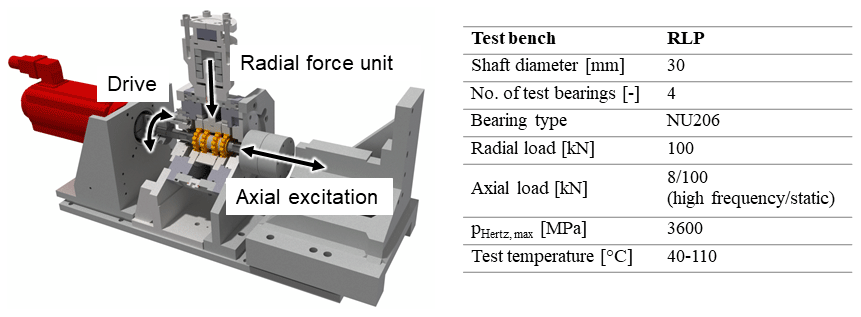
Four-bearing test bench: the investigations regarding the detection of operating conditions were conducted on a four-bearing test bench (Fig. 1). This test rig consists mainly of a drive unit, a radial-load unit, an oil chamber and four test bearings of type NU206-TVP2 with a bore diameter of 30 mm. The radial-load unit consists of a disc spring stack, which can be statically pre-loaded. The radial load is applied through the two middle test bearings. The test bearings are mounted on a shaft, which is driven by an electric motor (max. 6000 rpm). The loaded shaft itself is mounted in the test head by the outer test bearings, which are each arranged symmetrically to each other, ensuring a symmetrical load distribution on the test bearings.
Thrust bearing test bench: the fatigue-related tests in this work were carried out using cylindrical roller thrust bearings of type 81212 in an FE8-type test rig (Deutsches Institut für Normung e. V., 2016; see Fig. 2). The standard FE8 uses a constant load spring system, designed for bearing loads up to 100 kN. Using an electrical drive, it is possible to set up a shaft speed between 7.5–300 rpm. If a limit bearing temperature or vibration level is exceeded (e.g. caused by a pitting), the test will be stopped automatically. Two test bearings are used for each test run. These are often distinguished on the basis of their position within the test rig. Thus, there is a bearing at the motor side and a bearing at the housing side of the test rig. Each bearing consists of two washers, a cage and the rolling elements. One washer is mounted on the shaft and is driven, while the other one is stationary and placed in the housing.
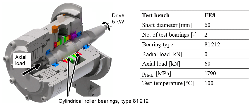
Figure 2FE8-type test rig with test bearings of type 81212 according to the Deutsches Institut für Normung e. V (2016).
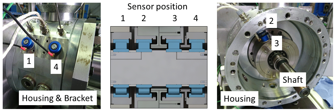
Acoustic-emission sensors: beside classic vibration sensors, acoustic-emission sensors were used. The sensors are broadband sensors (Model: QWT-MCX) of the company QASS and shown in Fig. 3. Unfortunately, no frequency response diagram of the sensor was available at the time of publication.

Although both methods rely on the same operating principle, the acoustic-emission (AE) sensors have no seismic mass. As a result, AE sensors can be used in higher frequency bands (Cockerill, 2017), often with range of 100 to 1000 kHz. On the other hand, vibration sensors operate in a band between 0 and 50 kHz. Therefore, AE operates outside the frequency range of classic machine vibrations and is less sensitive towards typical background noises such as the test bench cooling system (Physical Acoustics Corporation, 2015). Nevertheless, our own research has shown that a variety of high frequencies cause noise that reduces the signal-to-noise ratio. To increase the accuracy, the sensors need to be installed as close as possible to the rolling contacts.
In the case of the four-bearing test bench, four sensors were installed. For the middle test bearings (nos. 2 and 3) the sensors can be easily installed within the test head, as shown in Fig. 4. In the case of the outer test bearings (nos. 1 and 4) the sensors need to be installed outside the housing due to lack of space.
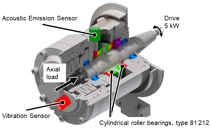
For use on the thrust bearing test rig, the sensors had to be installed outside the housing again due to the lack of space. The actual installation position of the sensors is shown in Fig. 5. While the vibration sensor is preferably placed in the direction of excitation, our own preliminary investigations show that AE sensors mounted in the displayed position provide the best results due to the short distance to the roller bearings. A positioning in direct proximity to the vibration sensor would be technically possible but results in a significant increase in the required component crossings and the distance to the bearings in general and thus in a change in and lowering of the AE signals.
The aim of this work is to investigate sensitivities of the AE system towards operating conditions causing roller bearing failures on one hand and on the other hand to investigate the differences regarding the detection time of AE and typical WT vibration sensors in order to assess the potential of AE for premature detection of bearing damages. In addition, it is discussed whether the development of sub-surface-initiated rolling-bearing damage can be detected by the AE system
4.1 AE sensitivities towards the detection of operating conditions
Typical failure modes of roller bearings in wind turbine gearboxes are micro-pitting, smearing (scuffing, rehardening) and white etching cracks, as shown in Sheng (2015). A short explanation of these failure modes can be found in previous work (Cornel et al., 2020). In addition, the following literature is recommended for more detailed insight: Bongardt (2015), van Lier (2015), Gutiérrez Guzmán et al. (2018, 2020).
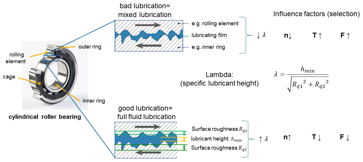
Generally speaking, the operating conditions of a bearing depend on the load (F), the shaft speed (n), the resulting bearing temperature (T), the lubricant and the roughness of bearing components. In this work a ISO VG 100 lubricant was used. Furthermore, it was ensured that the roughness of the used bearings was between 0.03 and 0.08 µm. The aforementioned factors are used to calculate the specific lubricant film thickness λ, which is used as a quantitative indicator of the lubricating conditions prevailing in the contact area. Values of λ≥3 indicate full-fluid-lubrication conditions, values of λ≤1 indicate boundary lubrication conditions, and the range between is referred to as a mixed-lubrication regime (Czichos and Habig, 2015). An operation under full fluid lubrication is intended in general. For the calculation of lubricant film thickness, the reader is referred to the work of Dowson and Higginson (Dowson and Higginson, 1966). In Fig. 6, the main influencing parameters are briefly highlighted.
It should be noted that the possible influence of static and dynamic load levels, slide–roll ratio, stillstand and current passage is consciously neglected in this work.
The abovementioned failure modes (micro-pitting, smearing, white etching cracks) are among other things promoted by boundary and mixed-lubrication conditions. Under full-fluid-lubrication conditions, the surfaces are completely separated, and the maximum stress shifts further below the surface, which is a prerequisite for typical rolling-contact fatigue damage. Using the influencing factors on the specific film thickness such as e.g. shaft speed, temperature and load, specific lubricating conditions can be set on a test bench.
The following experiment regarding the influence of the lubrication regime was part of a test series presented in previous work (Cornel et al., 2020). Due to the strong dependence of the specific lubricant film thickness on the oil, temperature was used to adjust different lubrication conditions. To expand the parameter field, two different shaft speeds – 500 and 3000 rpm – were used. The investigations were carried out at a constant pressure of 2.0 GPa, while the temperature itself was varied between 30 and 130 ∘C.
Figure 7 shows the results of the experiments.

Figure 7Influence of the lubrication regime and the shaft speed on the AE Energy level. Arb. unit: arbitrary unit.
It can be observed that the amplitude of the AE signals increases as lambda decreases. This is especially noticeable in the areas around λ = 0.5–2. At 500 rpm (Fig. 7, left) and λ > 2 the amplitude remains almost constant. The results meet the expectations that an increasing separation of the surfaces, defined by an increasing lambda, leads to decreased acoustic signals due to the missing interaction of roughness asperities within the contact. On the other hand, at 3000 rpm (Fig. 7, right) the effect of the AE amplitude remaining constant can only be seen by the external sensors, 1 and 4, at λ values > 5. Sensors 2 and 3 still show a significant decrease in the amplitude with an increasing lambda. This could be explained as follows: the transfer path of the acoustic signals to the externally mounted sensors has two additional component transitions due to the test rig design and is about 350 % longer compared to the internally mounted sensors. This consideration can lead to the fact that the signals become weaker and may no longer be detected. Regarding the significant decrease in the amplitude with an increasing lambda at 3000 rpm, it is assumed that due to the significantly higher shaft speed, the whole system is excited (e.g. the vibration of the test rig itself, increase in the bearing over rolling frequencies) much more, therefore resulting in a higher amplitude of the signals. Figure 8 arranges the results with the conducive conditions of the aforementioned failure modes. In conclusion it can be said that for a known system or test bench, the magnitude of the AE amplitude can be used to approximately determine the rotation speed range of the system.
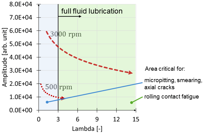
In addition, it is possible to distinguish between mixed friction and full fluid lubrication for the corresponding speed level. Therefore it can be concluded that a first analysis of the criticality of the prevailing conditions accompanied by an estimation of the expected failure mechanism could be carried out by using a CMS based on AE as long as the system is known from previous investigations, or a measurement phase is implemented during the set-up process.
4.2 Development of roller bearing damage
In order to compare the time to failure detection of CMSs based on AE and vibration under known conditions, the thrust bearing test rig (“FE8”) introduced in Sect. 3 was used. This test rig was chosen because it allows the generation of bearing damage within a short period of time. Due to the recent relevance, conditions were chosen which additionally lead to white etching crack (WEC) damage. WEC-induced bearing failure can occur after 5 %–20 % of the L10 nominal lifetime (Evans, 2015) and is therefore considered to be particularly critical. Further information can be found in the work of Danielsen et al. (2017). The testing was carried out within a short period of time (< 500 h) using well-known operating conditions. The test conditions are characterised by an axial load of 60 kN, a shaft speed of 300 rpm and a bearing temperature of 100 ∘C. These conditions have been previously used in further FE8-related WEC studies such as Danielsen et al. (2019). As shown in the work of Danielsen et al. (2019) these conditions usually lead to failures between 100 and 300 h.
During testing and as aforementioned, the signals of a vibration sensor and an AE sensor were monitored continuously during testing. Figure 9 shows both averaged signals from one test over the total test time of ∼ 261 h. The signal of the vibration sensor, shown as a red line, is plotted as the root mean square (RMS) and therefore marked as RMS. In contrast the AE signal, plotted as a green line, shows the amplitude average and is marked as AE average. The test was stopped after 261 h due to the vibration signal exceeding the vibration threshold (20 % above the RMS value after run-in). Post-testing analysis confirmed pitting damage as the source of the increased vibration.
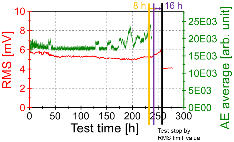
Figure 9Comparison of vibration and AE signal over the test time. Arb. unit: arbitrary unit.
Regarding the signal behaviour, both show a decreasing tendency within the first 50 h. This tendency can be correlated with typical running-in processes (e.g. smoothing of the roughness peaks on the bearing surface). Subsequently, the vibration signal stays at an almost-constant level before it rises significantly approx. 16 h before the threshold is exceeded. In contrast, the averaged AE signal shows the first indications of a deviation from its constant level after a test time of 125 h. These deviations increase significantly from about 150 and 175 h onwards. Unfortunately, it should be noted that the last 16 h of the AE signal are missing due to a recording error. In comparison with the vibration sensor, it can be concluded that significant activities of the AE system are visible at least 8 h before the vibration signal rises (referring to the latest peak of the AE signal before the test stop). It is assumed that the latest AE signal activities together with the increased AE signal level in general can be traced back to the formation of the pitting or to the outbreak of the surface. The preceding activities are possibly caused by sub-surface damage initiation and propagation. These deviations were detected up to ∼ 50 % (130 h) before the test stop and are potentially related to sub-surface damage initiation and might result in an earlier damage detection in the future. In general, AE signals can be associated, on a model level (see Sect. 2), to damage pre-stages, such as crack initiation, crack propagation or structural changes inside the bearing components. As described in Sect. 2, the correlation of the AE signals to specific phenomena is however still a research subject. As a basis for the future investigation of the topic, the signals should be examined for characteristic attributes and validated in further experiments.
In the conducted work two key aspects were covered: on the one hand, to analyse the sensitivities of the acoustic-emission (AE) system towards operating conditions causing failures at radial roller bearings and on the other hand to give a statement regarding pre-warning times for upcoming damages using AE and typical WT vibration sensors. In addition, it is discussed whether the development of sub-surface-initiated rolling-bearing damage can be detected by the AE system.
The investigations on the radial-bearing test bench have shown that the magnitude of the AE amplitude can be used to roughly determine the rotation speed range of a known system. In addition, it is possible to distinguish between an operation under a mixed-friction and full-fluid-lubrication regime for the corresponding rotation speed. Therefore, this study offers a first analysis of the theoretical criticality of the prevailing conditions accompanied by an estimation of the expected failure mechanism.
The investigations regarding the damage detection using a thrust bearing test rig (FE8) have shown that pitting damage could be detected by the AE system at least ∼ 4 % (8 h) in advance of the vibration-based system. Furthermore, noticeable deviations in the AE signal were detected up to ∼ 50 % (130 h) before the test stop and are possibly associated with damage pre-stages, such as crack initiation, crack propagation or structural changes inside the bearing components, and might result in an earlier damage detection in future. Besides, it was found that the AE system and the vibration-based system are capable of detecting the run-in period of a test run.
In the next step, the results are going to be validated on WT-size bearings. For this purpose a new four-bearing test bench with a shaft diameter of 180 mm will be used. Furthermore, it will be attempted to analyse the signals on a more detailed level to obtain further and more general information.
The underlying data of the acoustic-emission sensors are no longer available due to a hard disk defect in the acoustic emission system. The processed data can be taken from the graphs.
The concept and method of the present study were developed by DC, FGG and SN. DC performed the experiments as well as the initial text creation and visualisation. DC and FGG reviewed and edited the document. GJ and SN were responsible for supervision and final approval. GJ and SN acquired the funding. All authors have read and agreed to the published version of the paper.
The authors declare that they have no known competing financial interests or personal relationships that could have appeared to influence the work reported in this paper.
This article is part of the special issue “Wind Energy Science Conference 2019”. It is a result of the Wind Energy Science Conference 2019, Cork, Ireland, 17–20 June 2019.
The authors would like to thank the European Union and the German federal state of North-Rhine Westphalia (NRW) for the financial funding. They would also like to thank the Leitmarktagentur.NRW for the academic and administrative project support and all industrial partners for the good teamwork.
This research has been supported by the EFRE (grant no. EFRE-0800565).
This open-access publication was funded
by the RWTH Aachen University.
This paper was edited by Raimund Rolfes and reviewed by three anonymous referees.
Al-Ghamd, A. M. and Mba, D.: A comparative experimental study on the use of acoustic emission and vibration analysis for bearing defect identification and estimation of defect size, Mech. Syst. and Signal Pr., 20, 1537–1571, https://doi.org/10.1016/j.ymssp.2004.10.013, 2006.
Barteldes, S., Walther, F., and Holweger, W.: Wälzlagerdiagnose und Detektion von WEC mit Barkhausen-Rauschen und Hochfrequenz-Impuls-Messung, https://doi.org/10.13140/2.1.3910.3047, 2014.
Bongardt, C.: Wälzlagergraufleckigkeit, Dissertation, Verlagsgruppe Mainz GmbH, Aachen, ISBN 978-3-95886-089-6, 2015.
Bruzelius, K. and Mba, D.: An initial investigation on the potential applicability of Acoustic Emission to rail track fault detection, NDT&E Int., 37, 507–516, https://doi.org/10.1016/j.ndteint.2004.02.001, 2004.
Caesarendra, W., Kosasih, B., Tieu, A. K., Zhu, H., Moodie, C. A. S., and Zhu, Q.: Acoustic emission-based condition monitoring methods: Review and application for low speed slew bearing, Mech. Syst. Signal Pr., 72–73, 134–159, https://doi.org/10.1016/j.ymssp.2015.10.020, 2016.
Choudhury, A. and Tandon, N.: Application of acoustic emission technique for the detection of defects in rolling element bearings, Tribol. Int., 33, 39–45, https://doi.org/10.1016/S0301-679X(00)00012-8, 2000.
Cockerill, A., Clarke, A., Pullin, R., Bradshaw, T., Cole, P., and Holford, K. M.: Determination of rolling element bearing condition via acoustic emission, P. I. Mech. Eng. J-J. Eng., 230, 1377–1388, https://doi.org/10.1177/1350650116638612, 2016.
Cockerill, A.: Damage Detection of Rotating Machinery, available at: http://orca.cf.ac.uk/id/eprint/105671 (last access: 29 June 2019), 2017.
Cornel, D., Guzmán, F. G., Jacobs, G., and Neumann, S.: Acoustic Response of Roller Bearings Under Critical Operating Conditions, in: Engineering Assets and Public Infrastructures in the Age of Digitalization, Lecture Notes in Mechanical Engineering, edited by: Liyanage, J., Amadi-Echendu, J., and Mathew, J., Springer, Cham, https://doi.org/10.1007/978-3-030-48021-9_82, 2020.
Couturier, J. and Mba, D.: Operational Bearing Parameters and Acoustic Emission Generation, J. Vib. Acoust., 130, 24502, https://doi.org/10.1115/1.2776339, 2008.
Czichos, H. and Habig, K.-H.: Tribologie-Handbuch: Tribometrie, Tribomaterialien, Tribotechnik, Springer Fachmedien Wiesbaden, Wiesbaden, 794 pp., 2015.
Danielsen, H. K., Gutiérrez Guzmán, F., Dahl, K. V., Li, Y. J., Wu, J., Jacobs, G., Burghardt, G., Fæster, S., Alimadadi, H., Goto, S., Raabe, D., and Petrov, R.: Multiscale characterization of White Etching Cracks (WEC) in a 100Cr6 bearing from a thrust bearing test rig, Wear, 370–371, 73–82, https://doi.org/10.1016/j.wear.2016.11.016, 2017.
Danielsen, H. K., Gutiérrez Guzmán, F., Muskulus, M., Rasmussen, B. H., Shirani, M., Cornel, D., Sauvage, P., Wu, J., Petrov, R., and Jacobs, G.: FE8 type laboratory testing of white etching crack (WEC) bearing failure mode in 100Cr6, Wear, 434–435, 202962, https://doi.org/10.1016/j.wear.2019.202962, 2019.
Deutsches Institut für Normung e. V.: Testing of lubricants – Mechanical-dynamic testing in the roller bearing test apparatus FE8: Part 1: General working principles, Beuth Verlag GmbH, Berlin, 11 pp., 2016.
DGZfP: Kompendium Schallemissionsprüfung Acoustic Emission Testing (AT): Grundlagen, Verfahren und praktische Anwendung, available at: http://www.dgzfp.de/Portals/24/PDFs/FA/KompendiumAT.pdf (last access: 11 July 2019), 2011.
Dowson, D. and Higginson, G. R.: Elastohydrodynamic lubrication: The Fundamentals of Roller and Gear Lubrication, Pergamon Press, London, 124 pp., https://doi.org/10.1016/0043-1648(67)90018-X, 1966.
Eftekharnejad, B., Carrasco, M. R., Charnley, B., and Mba, D.: The application of spectral kurtosis on Acoustic Emission and vibrations from a defective bearing, Mech. Syst. Signal Pr., 25, 266–284, https://doi.org/10.1016/j.ymssp.2010.06.010, 2011.
Elasha, F., Greaves, M., Mba, D., and Fang, D.: A comparative study of the effectiveness of vibration and acoustic emission in diagnosing a defective bearing in a planetry gearbox, Appl. Acoust., 115, 181–195, https://doi.org/10.1016/j.apacoust.2016.07.026, 2017.
Elforjani, M.: Diagnosis and prognosis of slow speed bearing behavior under grease starvation condition, Struct. Health Monit., 17, 532–548, https://doi.org/10.1177/1475921717704620, 2018.
Elforjani, M. and Mba, D.: Detecting natural crack initiation and growth in slow speed shafts with the Acoustic Emission technology, Eng. Fail. Anal., 16, 2121–2129, https://doi.org/10.1016/j.engfailanal.2009.02.005, 2009.
Elforjani, M. and Mba, D.: Condition Monitoring of Slow-Speed Shafts and Bearings with Acoustic Emission, Strain, 47, 350–363, 2011.
Evans, M.-H.: An updated review: White etching cracks (WECs) and axial cracks in wind turbine gearbox bearings, Mater. Sci. Tech., 32, 1133–1169, 1–37, https://doi.org/10.1080/02670836.2015.1133022, 2015.
Ferrando Chacon, J. L., Artigao Andicoberry, E., Kappatos, V., Asfis, G., Gan, T.-H., and Balachandran, W.: Shaft angular misalignment detection using acoustic emission, Appl. Acoust., 85, 12–22, https://doi.org/10.1016/j.apacoust.2014.03.018, 2014.
Ferrando Chacon, J. L., Kappatos, V., Balachandran, W., and Gan, T.-H.: A novel approach for incipient defect detection in rolling bearings using acoustic emission technique, Appl. Acoust., 89, 88–100, https://doi.org/10.1016/j.apacoust.2014.09.002, 2015.
Ferrari, G. and Gómez, M. P.: Correlation Between Acoustic Emission, Thrust and Tool Wear in Drilling, Proc. Mater. Sci., 8, 693–701, https://doi.org/10.1016/j.mspro.2015.04.126, 2015.
Filippov, A. V., Rubtsov, V. E., and Tarasov, S. Y.: Acoustic emission study of surface deterioration in tribocontacting, Appl. Acoust., 117, 106–112, https://doi.org/10.1016/j.apacoust.2016.11.007, 2017.
Fritz, M., Burger, W., and Albers, A.: Schadensfrüherkennung an geschmierten Gleitkontakten mittels Schallemissionsanalyse, Tribologie Fachtagung, 1. Jg., p. 30-1, 2001
Gutiérrez Guzmán, F., Özel, M., Jacobs, G., Burghardt, G., Broeckmann, C., and Janitzky, T.: Influence of Slip and Lubrication Regime on the Formation of White Etching Cracks on a Two-Disc Test Rig, Lubricants, 6, 8, https://doi.org/10.3390/lubricants6010008, 2018.
Gutiérrez Guzmán, F., Sous, C., van Lier, H., and Jacobs, G.: An energetic approach for the prognosis of thermally induced white etching layers in bearing steel 100CrMn6, Tribol. Int., 143, 106096, https://doi.org/10.1016/j.triboint.2019.106096, 2020.
Han, Z., Luo, H., Cao, J., and Wang, H.: Acoustic emission during fatigue crack propagation in a micro-alloyed steel and welds, Mat. Sci. Eng. A, 528, 7751–7756, https://doi.org/10.1016/j.msea.2011.06.065, 2011.
Leaman, F., Hinderer, S., Baltes, R., Clausen, E., Rieckhoff, B., Schelenz, R., and Jacobs, G.: Acoustic Emission Source Localization in Ring Gears from Wind Turbine Planetary Gearboxes, Forsch. Ingenieurwes., 83, 43–52, https://doi.org/10.1007/s10010-018-00296-4, 2019.
Marfo, A., Chen, Z., and Li, J.: Acoustic emission analysis of fatigue crack growth in steel structures, Journal of civil engineering and construction Technology, 2013, 4. Jg., Nr. 7, 239–249, 2013.
Miettinen, J. and Andersson, P.: Acoustic emission of rolling bearings lubricated with contaminated grease, Tribol. Int., 33, 777–787, https://doi.org/10.1016/S0301-679X(00)00124-9, 2000.
Mirhadizadeh, S. A., Moncholi, E. P., and Mba, D.: Influence of operational variables in a hydrodynamic bearing on the generation of acoustic emission, Tribol. Int., 43, 1760–1767, https://doi.org/10.1016/j.triboint.2010.03.003, 2010.
Mokhtari, N., Grzeszkowski, M., and Gühmann, C.: Vibration Signal Analysis for the Lifetime-Prediction and Failure Detection of Future Turbofan Components, J. Eng. Mech., 37, 422–431, https://doi.org/10.24352/UB.OVGU-2017-118, 2017.
Mokhtari, N., Gühmann, C., and Nowoisky, S.: Approach for the Degradation of Hydrodynamic Journal Bearings based on Acoustic Emission Feature Change: 11–13 June 2018, IEEE, Piscataway, NJ, 1–5, 2018.
Morhain, A. and Mba, D.: Bearing defect diagnosis and acoustic emission, Proceedings of the Institution of Mechanical Engineers, Part J: Journal of Engineering Tribology, 217, 257–272, https://doi.org/10.1243/135065003768618614, 2003.
Morton, T. M., Harrington, R. M., and Bjeletich, J. G.: Acoustic emissions of fatigue crack growth, Eng. Fract. Mech., 5.3, 691–697, 1973.
Physical Acoustics Corporation: Acoustic Emission Measurement training materials, available at: https://www.physicalacoustics.com/, last access: 12 November 2015.
Poddar, S. and Tandon, N.: Detection of particle contamination in journal bearing using acoustic emission and vibration monitoring techniques, Tribol. Int., 134, 154–164, https://doi.org/10.1016/j.triboint.2019.01.050, 2019.
Qu, Y., He, D., Yoon, J., van Hecke, B., Bechhoefer, E., and Zhu, J.: Gearbox tooth cut fault diagnostics using acoustic emission and vibration sensors – a comparative study, Sensors, 14, 1372–1393, https://doi.org/10.3390/s140101372, 2014.
Roberts, T. M. and Talebzadeh, M.: Fatigue life prediction based on crack propagation and acoustic emission count rates, J. Constr. Steel Res., 59, 679–694, https://doi.org/10.1016/S0143-974X(02)00065-2, 2003.
Scheer, C., Reimche, W., and Bach, F.-W.: Early fault detection at gear units by acoustic emission and wavelet analysis, J. Acoust. Emiss, 25, 331–340, 2007.
Schnabel, S., Marklund, P., Larsson, R., and Golling, S.: The detection of plastic deformation in rolling element bearings by acoustic emission, Tribol. Int., 110, 209–215, https://doi.org/10.1016/j.triboint.2017.02.021, 2017.
Sheng, S.: Wind turbine gearbox reliability database, condition monitoring, and operation and maintenance research update, No. NREL/PR-5000-66028, National Renewable Energy Lab. (NREL), Golden, CO, United States, 2015.
Shiroishi, J., Li, Y., Liang, S., Kurfess, T., and Danyluk, S.: Bearing condition diagnostics via vibration and Acoustic Emission measurements, Mech. Syst. and Signal Pr., 11, 693–705, https://doi.org/10.1006/mssp.1997.0113, 1997.
Singh, P. J., Mukhopadhyay, C. K., Jayakumar, T., Mannan, S. L., and Raj, B.: Understanding fatigue crack propagation in AISI 316 (N) weld using Elber's crack closure concept: Experimental results from GCMOD and acoustic emission techniques, International Journal of Fatigue, 29, 2170–2179, https://doi.org/10.1016/j.ijfatigue.2006.12.013, 2007.
Tchakoua, P., Wamkeue, R., Ouhrouche, M., Slaoui-Hasnaoui, F., Tameghe, T., and Ekemb, G.: Wind Turbine Condition Monitoring: State-of-the-Art Review, New Trends, and Future Challenges, Energies, 7, 2595–2630, https://doi.org/10.3390/en7042595, 2014.
van Hecke, B., Yoon, J., and He, D.: Low speed bearing fault diagnosis using acoustic emission sensors, Appl. Acoust., 105, 35–44, https://doi.org/10.1016/j.apacoust.2015.10.028, 2016.
van Lier, H.: Neuhärtungsgefährdung von Radial-Zylinderrollenlagern durch Lastaufschaltungen in Betriebspunkten mit Käfigschlupf, Zugl.: Aachen, Techn. Hochsch., Diss., Mainz, Aachen, 108 pp., 2015.
Venkata Rao, K. and Murthy, P. B. G. S. N.: Modeling and optimization of tool vibration and surface roughness in boring of steel using RSM, ANN and SVM, J. Intell. Manuf., 29, 1533–1543, https://doi.org/10.1007/s10845-016-1197-y, 2018.
Zhang, L., Ozevin, D., Hardman, W., and Timmons, A.: Acoustic Emission Signatures of Fatigue Damage in Idealized Bevel Gear Spline for Localized Sensing, Metals, 7, 242, https://doi.org/10.3390/met7070242, 2017a.
Zhang, Y., Lu, W., and Chu, F.: Planet gear fault localization for wind turbine gearbox using acoustic emission signals, Renew. Energ., 109, 449–460, https://doi.org/10.1016/j.renene.2017.03.035, 2017b.
Zohora, F.: Evaluation of material crack using acoustic emission technique, Doctoral dissertation, Queensland University of Technology, Queensland, 123 pp., 2016.