the Creative Commons Attribution 4.0 License.
the Creative Commons Attribution 4.0 License.
 | 05 Jan 2022
Evaluation of the impact of active wake control techniques on ultimate loads for a 10 MW wind turbine
Alessandro Croce
Stefano Cacciola
Luca Sartori
Wind farm control is one of the solutions recently proposed to increase the overall energy production of a wind power plant.
A generic wind farm control is typically synthesized so as to optimize the energy production of the entire wind farm by reducing the detrimental effects due to wake–turbine interactions. As a matter of fact, the performance of a farm control is typically measured by looking at the increase in the power production, properly weighted through the wind statistics. Sometimes, fatigue loads are also considered in the control optimization problem. However, an aspect which is rather overlooked in the literature on this subject is the evaluation of the impact that a farm control law has on the individual wind turbine in terms of maximum loads and dynamic response under extreme conditions.
In this work, two promising wind farm controls, based on wake redirection (WR) and dynamic induction control (DIC) strategy, are evaluated at the level of a single front-row wind turbine. To do so, a two-pronged analysis is performed. Firstly, the control techniques are evaluated in terms of the related impact on some specific key performance indicators, with special emphasis on ultimate loads and maximum blade deflection. Secondarily, an optimal blade redesign process is performed with the goal of quantifying the modification in the structure of the blade entailed by a possible increase in ultimate values due to the presence of wind farm control. Such an analysis provides for an important piece of information for assessing the impact of the farm control on the cost-of-energy model.
- Article
(3901 KB) - Full-text XML
- BibTeX
- EndNote


So far, the majority of the works devoted to wind farm control have been aimed at evaluating the effectiveness of such techniques as means of power harvesting maximization. Among all, one can mention the methodologies based on wake steering (see Fleming et al., 2019; Gebraad et al., 2017, 2016), steady axial induction (see Annoni et al., 2016) and dynamic induction control, also called active wake mixing (see Munters and Meyers, 2018, 2017). When it comes to farm control synthesis, the energy production is typically viewed as the most significant merit figure, and seldom are the fatigue loads on a single wind turbine (WT) considered within the control optimization problem (Bossanyi, 2018; Knudsen et al., 2015).
The quantification of the impact of wind farm control set point on turbine fatigue, needed for any load assessment process, has been the object of extensive research in recent years, especially in relation to yawed operations (Cardaun et al., 2019; Ennis et al., 2018; White et al., 2018). All works suggested that the impact of misalignment depends strongly on ambient conditions (such as vertical shear and turbulence intensity).
Boorsma (2012) evaluated the fatigue loads of a 2.5 MW turbine operating in misaligned conditions using different aerodynamic models and compared the results with field measurements. It was shown that the combination of vertical shear layer and misalignment may lead to an increase or decrease in fatigue loads, depending on the sign of the yaw misalignment angle.
A similar study, based on a dedicated and systematic field test campaign, for a 1.5 MW turbine, yielded similar conclusions (Damiani et al., 2018).
Zalkind and Pao (2016) analyzed the impact of wake redirection control in terms of fatigue loads considering a simple two-turbine cluster and a reference wind rose. The aggregate damage equivalent loads were computed from the actual yaw misalignment angles which the upstream turbine would experience for maximizing the total power of the cluster. In such an ideal case, the impact of wake redirection control resulted in being small due to the large amount of time spent with no yaw misalignment.
Mendez Reyes et al. (2019) and Kanev et al. (2018) considered the problem of quantifying the fatigue loads of downstream turbines impinged by the wakes shed by upstream machines. Both studies concluded that, in terms of loading, impinging wakes are typically more detrimental than operations with yaw misalignment. Consequently, wake redirection is expected to reduce the overall lifetime fatigue thanks to the mitigation of rotor–wake interactions.
Finally, Frederik et al. (2020b) provided the first evaluation of the impact of dynamic induction control on fatigue, considering a reference 5 MW turbine model.
Despite the availability of such relevant results, the question over the actual impact of farm control on rotor design is still an open question. In fact, while fatigue loads may even decrease in controlled farms, ultimate values for loads and blade tip deflections, typically coming from extreme events like gusts or faults, may significantly increase due to the different wind turbine operating conditions connected to the wind farm control. Ultimate loads, maximum tip displacements and fatigue loads participate together in the definitions of the constraints to which a machine is subject during the design phase. Hence, the possible increase in machine ultimate values due to wind farm control could determine whether a turbine structure is to be redesigned, with an eventual increase in its mass and cost, or not.
As expected, the advantages (i.e., the increased power production at farm level) and the disadvantages (i.e., the possible increased loading at turbine level) of a farm control should be combined to determine their impact in terms of cost of energy (CoE). In order to show this concept, one may consider the simple definition of the CoE of a single turbine, reported in Fingersh et al. (2006),
where FCR is the fixed charge rate; ICC the initial capital cost, consisting mainly of the turbine cost; and AOE the annual operating expenses (expressed per unit energy yield), which may include land or sea lease, operation and maintenance costs. Clearly, the AEP of a single turbine may be reduced or increased by the farm control according to the fact that a machine operates mainly upstream or downstream. The sum of the AEPs of all turbines belonging to the farm increases for a farm control neatly designed.
In addition, given a specific wind farm control technique, the component loading should be evaluated at the turbine level, so as to clarify if a generic turbine within a “controlled farm” would need a dedicated design. If so, the farm control, in addition to an expected increase in farm AEP, will also have an influence in terms of ICC.
The scope of this paper is twofold. First, we quantify the impact of wake steering and dynamic induction control at the level of the front-row turbine through some indicators strictly connected to machine design, which are the ultimate loads and the maximum blade tip deflection, computed according to the present standards. To the best of the authors' knowledge, the implications of farm control in terms of these indicators have never been addressed; hence this part of the work represents the major source of novelty of the paper. Second, in order to provide an insight into the impact of farm control on the cost of the rotor, an optimal blade redesign process is performed, which takes into consideration the possible influence that wind farm control has on blade ultimate loads and maximum blade tip deflections.
A complete procedure for a wind turbine design should, in principle, consider all the machines of the farm. To do so, it would be necessary to know the farm layout and the wind rose. This complex and site-specific procedure is out of the scope of this research activity, and hence the present analyses will focus only on the front-row wind turbine, i.e., the one which is subject to the undisturbed wind and has to operate according to the farm control inputs.
Clearly, in a single farm, there is a subset of machines which see a clean flow most of the time, i.e., the outermost ones exposed according to the most probable wind direction, and another subset of turbines, the innermost ones, which sometimes see a waked flow. In this scenario, since different turbines may be exposed to different flows on average, it is certainly interesting to evaluate a possible usage of partially customized or totally different turbines in a single farm, depending on the specific machine location. In such a case, the turbines proposed for some farm locations could be characterized by more competitive designs thanks to the farm control. Although extremely interesting, this idea falls out of the scope of the present paper. However, the final design process presented in Sect. 4.4 supports this investigation, providing a preliminary indication on the potential impact of farm controls on the rotor design of the front-row wind turbines.
Finally, in this work, all analyses are performed on the INNWIND.EU 10 MW wind turbine (Bak et al., 2013), which can be considered a generic reference model for present and future machines proposed for the exploitation of on- and offshore resources.
The paper is organized as follows. Sections 2 and 3 deal with the explanation of the methodologies adopted to evaluate the impact of wind farm control at the single wind turbine level. These sections include the definition of the wind turbine used in the analysis and its controller, along with the description of the multibody software employed for the aeroservoelastic simulations and the optimal rotor design tool. In Sect. 4, a sensitivity analysis on the effects of two wind farm control techniques (i.e., WR and DIC) is considered. Specifically, ultimate loads and maximum blade tip deflection are evaluated considering different settings of the controls (e.g., different yaw misalignment angles for wake redirection) in order to find the most impacting conditions for the turbine. Such sensitivity analysis is viewed as a preliminary step for the optimal blade design process which is described in Sect. 4.4. Finally, Sect. 5 concludes the paper by listing the main findings and possible outlooks of the work.
Having an overview of the effects that a wind farm control may have on a single wind turbine and eventually quantifying its impact on the design of the rotor is not an easy task. In fact, when dealing with an entire wind farm, the problem of analyzing wind turbine performance becomes highly site-specific because the inputs of the farm control will depend on many factors, such as the farm layout, the wind distribution and rose, and the turbulence intensities. In such a scenario, deriving conclusions of general validity without focusing too much on a specific case is rather difficult.
Moreover, wind turbines are designed according to international standards, which prescribe the computation of fatigue and ultimate loads in a certain number of conditions, e.g., for specific wind speeds and turbulence intensity levels.
A recent position paper on certification and standardization issues of wind farm control considers, among all, the problem of the integration of this new technology into the current regulatory framework (FarmConners deliverable D2.1, 2020). According to that position paper, although existing standards do not explicitly cover the wind farm control case, they can be used for this aim following three practical approaches, based on long-term measurements, risk-based certifications or temporary allowance to test novel control applications. Additionally, standards offer some tools that could be useful to handle design of wind turbines operating in a controlled farm. For example, IEC (2005) suggests either (a) verifying that the specific flow conditions at single turbine locations are covered by the reference wind statistics or (b) simulating the site-specific loads through the straightforward added-turbulence Frandsen model (Frandsen, 2007). The recently published IEC (2019), in order to assist load assessment of a specific turbine, also proposes a wake meandering model, which is expected to be more adequate than added-turbulence techniques.
Notwithstanding the present regulatory framework that offers such possibilities, the authors of the position paper admit that applying the current standards to a specific project can be challenging and that a fast and accurate calculation of loads is needed for designing turbines in all positions of the farm in case a wind farm control law is implemented. In this scenario, the possible increase in fatigue and ultimate loads certainly represents a risk to carefully handle for the future practical usage of wind farm controls.
This discussion highlights the topicality of the object of the present work, mainly focused on the impact of farm controls on ultimate loads. In fact, as already mentioned in Sect. 1, much has been done in terms of fatigue but, at the same time, much is still to be done for quantifying if and how the farm control modifies ultimate loads and maximum tip deflections, which are typical drivers for component design of modern wind turbine blades.
Although the response of downstream machines is surely influenced by the presence of wind farm controls, it is important to first provide a preliminary quantification of such an impact on upstream machines, i.e., those implementing a wake control logic. In this work, we will analyze only this case, and consequently the obtained results apply to only front-row wind turbines. This clearly represents a strong simplification of the problem, as one does not have to model the in-farm flow. In this regard, one could stress that real turbines operating in real farms typically experience wake interaction phenomena. Despite that, when a wind farm comes to its end of service, most turbines still have some residual life to exploit (Ziegler et al., 2018), even if wake impingement represents a significant source of loading (Mendez Reyes et al., 2019; Kanev et al., 2018). On the other side, operating according to the farm control, e.g., in prolonged misalignment conditions, also represents a clear source of risk for front-row turbines in light of the present regulatory framework. Accordingly, the choice of focusing only on the upstream turbines is not to be viewed as a limitation of the analysis but rather as a further step towards a comprehensive knowledge of positive and negative aspects of wind farm control in terms of its implication on the design of the machines.
Looking at the sole front-row wind turbines leads to a simplified analysis which takes into account only the well-known list of design load cases (see IEC, 2005, Sect. 7.4), to be neatly modified so as to include the operations under wind farm control inputs. In this regard, the work of this paper considers only a wind speed dependency of the control and imposes as a limit for its activation 15 m s−1 no matter the turbulence intensity (TI).
In order to have an indication of general validity, which may support further activities on the same topic, the analyses have been conducted as sensitivity studies. The effects of the wind farm control are considered functions of some important parameters. For example, the study of the wake redirection was carried out for different values of yaw misalignment, whereas that of the DIC was carried out for different frequency and amplitude values of the pitch oscillation. From this point of view, such a sensitivity analysis can be used as input for the synthesis and fine tuning of a farm control by reducing its authority in conditions which could be critical from the loading side.
For example, since a turbine operating in yawed conditions may be more exposed to extreme events (i.e., gusts or extreme shear), it could be interesting to bound the operational range of the controller within certain values of misalignment, in order to limit the increase in the design-driving loads.
Similarly, the amplitude and the frequency of the pitch motion for dynamic induction control can also be chosen by looking at the effect of fatigue and actuator duty cycle. This possibility, although interesting, is not considered in this paper, as it is out of its scope and will be further investigated as a follow-up of this work.
The next sections will show that, even if only the front wind turbine is investigated, the design loads, coming from extreme events, may increase under these wind farm control inputs.
Clearly, determining how much the loads could increase when considering the “internal” wind turbines is not possible with the present approach. Such an investigation is beyond the scope of this work.
To further investigate the effect of these wind farm controls, in the last section, a state-of-the-art procedure in which the rotor blades have been redesigned with the DIC algorithm enabled is presented. The goal of this last analysis is to quantify the changes in internal blade geometry required when the wind farm control is operating on the wind turbine itself. The subsequent increase in mass, and thus blade cost, is, in fact, an important and direct indicator of the impact of the wind farm control as discussed previously.
In this work we use the INNWIND.EU 10 MW wind turbine (Bak et al., 2013) as a reference for all parametric analyses and design activities.
All dynamic simulations are run by our in-house multibody solver Cp-Lambda (Bottasso and Croce, 2009–2018; Bottasso et al., 2006). This tool allows one to model the flexibility of blades, tower and shafts through a geometrically exact beam model (Bauchau, 2011), whose sectional structural properties are rendered through fully populated 6×6 stiffness matrices. Aerodynamics is rendered via the classical blade element momentum (BEM) theory with hub and tip losses and tower shadow. First- and second-order dynamical models are employed to include respectively generator and pitch actuator dynamics.
The control of the turbine in operating conditions is managed by the CL-WINDCON standard controller (CL-Windcon, 2016–2019; IK4 Research Alliance, 2016), while non-operating conditions like faults, startups, shutdowns and parking are all managed by the POLI-Wind Supervisor (Riboldi, 2012), which also supervises the transitions between different operating states.
The design and optimization activities are run by Cp-Max, a tool for the integrated design of wind turbines, jointly developed by Politecnico di Milano and the Technische Universität München. A detailed description of the algorithm, along with some design applications, is provided by Sartori (2019) and by Bortolotti et al. (2016).
Thanks to its multi-level architecture, Cp-Max is able to both optimize the main features of the turbine (rotor diameter, tower height, tilt and cone angle) and conduct specific optimization of turbine subcomponents like blades, tower and generator. This double capability is achieved through the coupling among a macro design loop (MDL) and several design submodules.
In this work, we only use the structural design submodule (SDS), whose workflow is shown in Fig. 1.
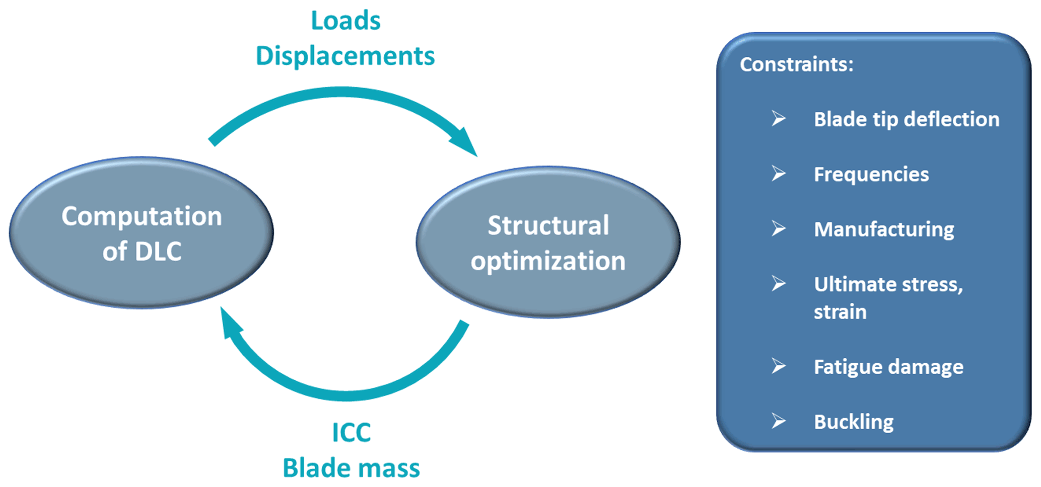
The purpose of the SDS is to manage the structural design of the rotor through a dedicated optimization in which the thicknesses of all structural components are sized to minimize the turbine ICC. As shown in Fig. 1, the structural optimization is conducted through a multi-step procedure: initially, an arbitrarily large set of design load cases (DLCs) is performed with Cp-Lambda to extract the driving loads and displacements from fully resolved aeroelastic simulations. Once maximum loads and displacements are computed, the structural optimization begins and the internal thicknesses are modified until a converged solution is found. Then, if the optimal blade mass is significantly different from the initial, the whole process (DLC and structural design) is repeated, so that the design can always account for the updated load spectra. Throughout this process, structural integrity constraints are enforced according to international certification guidelines. Those account for maximum deflections, stiffness, strength, possible manufacturing limitations, fatigue and buckling.
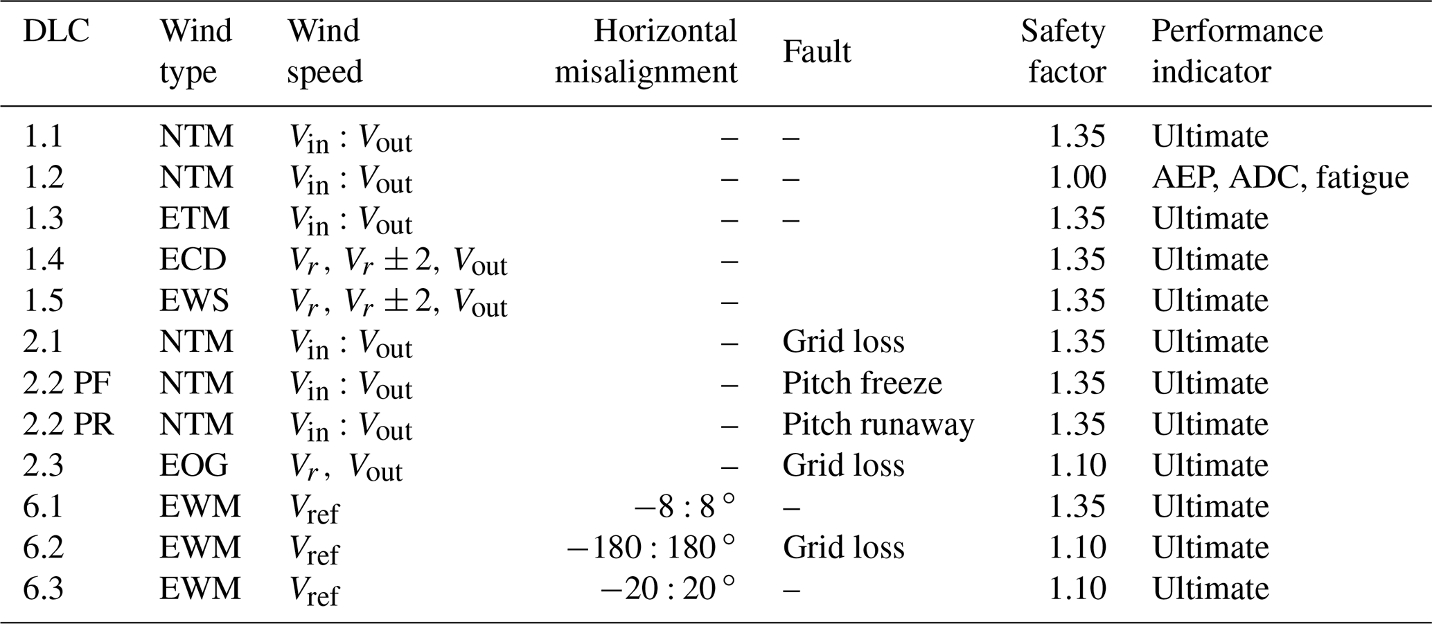
Given the complexity of the problem at hand, any design-oriented activity should be carefully planned out so as to identify the best trade-off between modeling accuracy, computational effort and design scope. In this view, we introduced some assumptions in order to find a good balance between scope and CPU time. Our first choice was to limit the redesign effort to the optimization of the blade structure. In fact, although wind farm controller may impact other parts of the turbine and possibly also blade shape, it is reasonable to expect that it mainly affects the driving loads, with important implications for rotor structure. As a consequence, the macro parameters of the wind turbine like the rotor radius and tower height have not been modified. Similarly, the aerodynamic shape of the rotor has been kept constant and coherent to that of the baseline. It must be noticed that, by introducing this scope limitation, it was possible to include a large set of fully resolved DLCs directly in the design, without the need to adopt any simplification on the load spectra. In particular, it was possible to use the set of DLCs listed in Table 1, defined according to the chosen standards (IEC, 2005). The entire set includes about 130 load cases, for a total computational time of 26–28 h on a common desktop.
As is clear from the fifth column of Table 1, the analyses performed in this work considered only failure modes related to the single turbine, without analyzing possible implications of malfunctions of wind farm control and its supporting technology. The relevant problem of wind farm control failure modes is currently an open topic to study. In general, as suggested in a recent report (CL-Windcon deliverable D4.7, 2019), a wind farm control can be practically implemented so as to minimize the impact that its possible failures may have on turbine operating conditions. In fact, in the case of conflict between the individual turbine regulators and farm controllers, the priority should be given to the former. Moreover, like any modern turbine has its own protection system, which can shut the machine down in case of critical conditions (e.g., strong wind and high vibrations), it is reasonable to think that farm controllers may also be equipped with similar devices: in case failures are detected, the farm controller is disengaged, and nominal operations based on greedy control are restored. This suggests that, at least for the goal of this work, although an interesting topic, the failure modes of farm control can be neglected within the DLC list.
Table 1Definition of the DLCs considered in the analyses. NTM: normal turbulence model; ETM: extreme turbulence model; ECD: extreme coherent gust with direction change; EWS: extreme wind shear; EOG: extreme operating gust; EWM: extreme wind speed model.
The standards require a turbine to be designed under a full list of load cases which include normal operative conditions, situations where the machine undergoes extreme events or faults and cases in which the turbine is parked. Obviously, in order to have a correct evaluation of the impact of farm control on ultimate loads, one has to also simulate those cases in which the farm control is certainly not active (e.g., parked conditions). In fact, one may imagine a situation in which, without wind farm control, a specific sub-component is sized on the basis of a particular ultimate load, noted U∗, coming from a parked condition (DL6.n). In this case, even if wind farm control entails an increase in machine loading in other operative conditions, unless such an increase is not enough to exceed U∗, the presence of wind farm control is irrelevant to that ultimate value and, in turn, to the design of that sub-component.
Along with the list of DLCs, it is necessary to select the range in which the wind farm control is active. Clearly, the activation of the wind farm control is based on the specific implementation of the control scheme and may depend on wind speed, turbulence intensity, geometry of the farm and even on combinations of the previous factors. In this very complex scenario, in order to simplify the analysis, the farm control is considered active only up to a given speed, chosen here as 15 m s−1, no matter the turbulence intensity or other factors.
4.1 Evaluation of the impact of wake redirection technique
In this section the effects of the wake redirection control on wind turbine loads and blade deflections are investigated.
The wind farm control based on the wake redirection technique consists in yawing an upstream turbine by a specific amount in order to deflect its wake out of one or more downstream turbines (Fleming et al., 2019; Gebraad et al., 2017, 2016). Within such a wind farm control scenario, while the upstream machine experiences a loss of power, due to the wind misalignment, the downstream ones produce more power thanks to a reduced wake impingement.
In this work, the turbine misalignment is reproduced in the simulations by rotating the nacelle. Positive angles are associated with counterclockwise rotations of the nacelle viewed from above. Hence, the turbine experiences positive yaw misalignment when the wind is coming from the right side, for an observer sitting on the hub and looking at the wind. In the reference configuration (i.e., for a null yaw angle) the wind is assumed to blow from north to south, and, accordingly, the nacelle is oriented towards north.
The study is then carried out as a sensitivity analysis, where the effects of different steady yaw misalignment angles between −30 and 30∘ are evaluated in terms of turbine fatigue, ultimate loads and maximum blade tip deflections.
The 10 MW INNWIND.EU model, implemented through the software Cp-Lambda, was subjected to the full list of DLCs described in Table 1. As already explained in Sect. 1, DLC6.n series was simulated only for the reference turbine (i.e., without misalignment), whereas DLC1.n and 2.n were simulated for reference and for four other different yaw misalignment angles (±15, ±30 ∘).
Once all load conditions have been calculated for each yaw angle, ultimate values are extracted for each wind turbine sub-component, having previously considered the relative safety factor as defined in Table 1. As explained above, the DLC6.n series are computed only for the baseline case, but maximum load and blade tip displacement values coming from those cases are also included in the ranking related to all misalignment angles.
As an example of this analysis, Fig. 2 shows in the top plots the ultimate load increment at different yaw angles for the blade root combined moment (a) and for the tower base combined moment (b). The text above each bar indicates the DLC which has generated such maximum loads. In terms of blade, the effect of yaw misalignment is limited with just a small increase of about 1 % at 30∘. Tower loading seems to suffer a bit more at high misalignment angles with an increase of 7.5 % at 30∘, due to a strong increment in the maximum load experienced in DLC1.4. On the other side, at lower angles, the ultimate value stays the same as it occurred in parking conditions (DLC6.2), no matter the presence of the farm control.
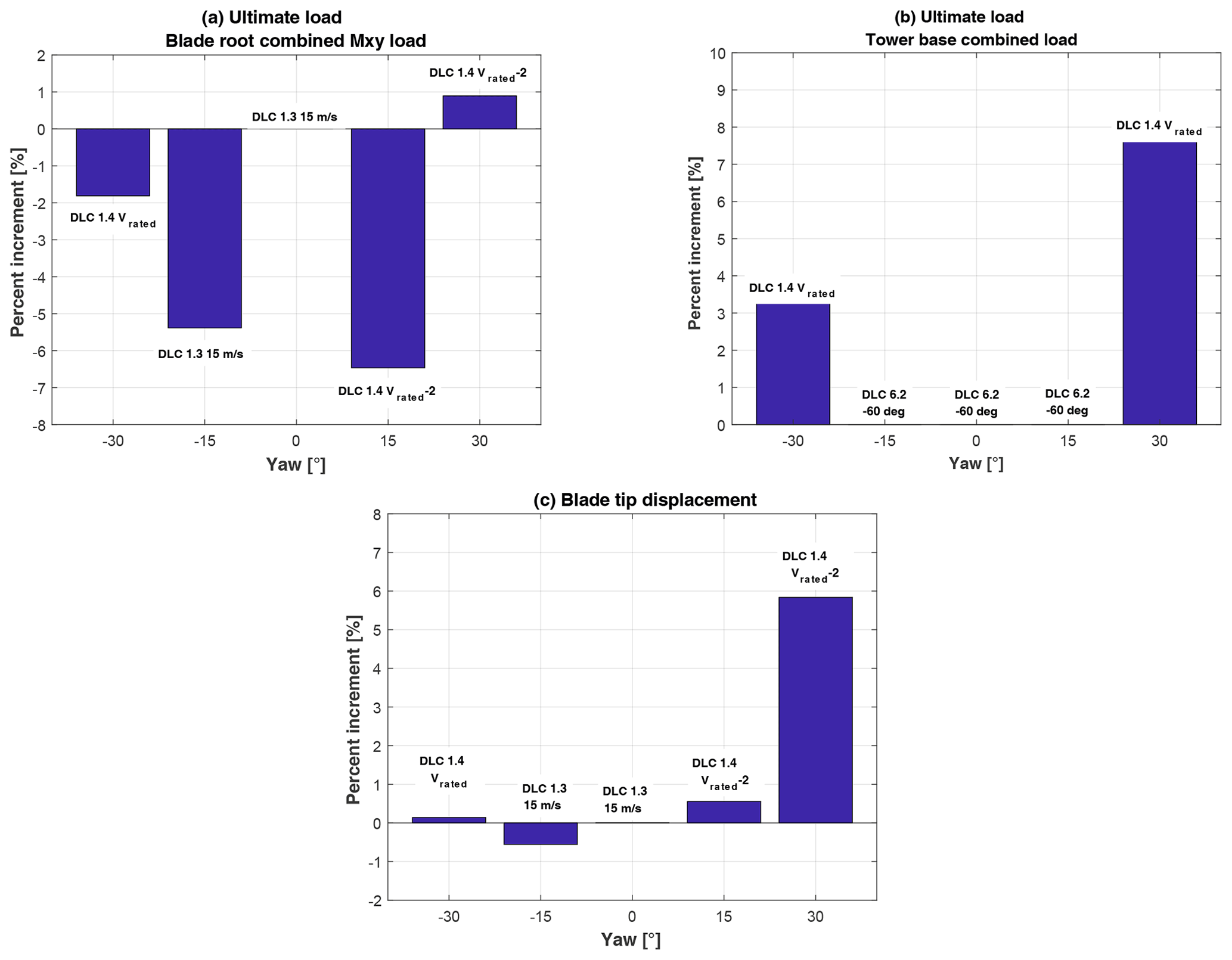
Figure 2Comparison of ultimate loads and maximum tip deflection. (a) Blade root combined moment. (b) Tower base combined moment. (c) Maximum blade tip displacement.
Similarly, the misalignment angle of 30∘ is also associated with an increase of about 6 % in the maximum blade tip displacement (see Fig. 2c). This increment, although apparently small, deserves special attention. In fact, often, the blade design is constrained by the maximum blade tip deflection, which is to be bounded in order to avoid dramatic blade-tower collision. Since the maximum tip deflection typically enters in the design process as a constraint, it is possible that even a small increment of this value may lead to a violation of this constraint and in turn to the need for a blade redesign. In this specific case, the maximum blade deflection occurred during the DLC1.4, i.e., during the ECD gust (extreme coherent gust with direction change), where an increase in the wind speed is coupled with a direction change. This combination causes the rotor to experience a much higher axial wind anytime the rotor itself is initially oriented as the direction the gust is coming from.
Finally, fatigue analysis is carried out on the basis of DLC1.2. Even if such analysis would require a more sophisticated approach, possibly, including all turbines in a farm, we briefly present here the direct effect of the wind farm controller on damage equivalent load (DEL) of the first-row wind turbine, i.e., the yawed one.
Figure 3a shows the blade root flap-wise DEL increment associated with the wake redirection for different yaw angles. All DELs have been computed in power production with turbulent wind from the cut-in to the cut-out wind speed (DLC1.2) and then weighted with the Weibull probability function for class IA (IEC, 2005). In this analysis, and in the following ones, an equivalent frequency corresponding to 10 M cycles in 20 years has been considered. Moreover, m=10 and m=3 have been used as inverse SN-curve slope (i.e., Wöhler exponent) values, for composite blades and the steel tower, respectively. It is important to stress here that only for wind speed lower than 15 m s−1 is the wind farm controller (i.e., the wake steering) active, so that at higher wind speeds there is no difference between the performance of baseline and wind-farm-controlled ones. As a side remark, limiting the activity of the farm control to 15 m s−1 is reasonable for controllers aimed at maximizing the power production. It is however possible to also have a farm control activity beyond this wind speed for downstream turbine fatigue mitigation, as proposed in Urbán et al. (2018). The same figure shows that the overall effect of the yaw misalignment on the cumulated DEL is limited, with an increase of slightly more than 3 % at −15∘. The reduction experienced in most of the positive misalignment range is due to the coupling between vertical shear layer and lateral flow velocity induced by yaw misalignment. In fact, vertical shear layer increases the blade loads when it is upward and decreases them when downward, generating a load oscillation at the rotor frequency. A lateral component of the wind is similarly responsible for oscillating loads, but with the difference that the increment may occur when the blade is upward or downward depending on whether the misalignment angle is positive or negative. As a consequence, the impact of yaw misalignment may be summed up to or subtracted from the one of the shear layer. This behavior is not new, as was also analyzed in Boorsma (2012) and Ennis et al. (2018).
Figure 3 shows the increment in the maximum directional DEL for the tower base as a function of the yaw angle. In this case these DELs have been computed looking for the worst direction as typically done for axial-symmetric structures. Again, operating in yawed conditions (for wind speed below 15 m s−1) does not seem critical in terms of fatigue for the tower base.
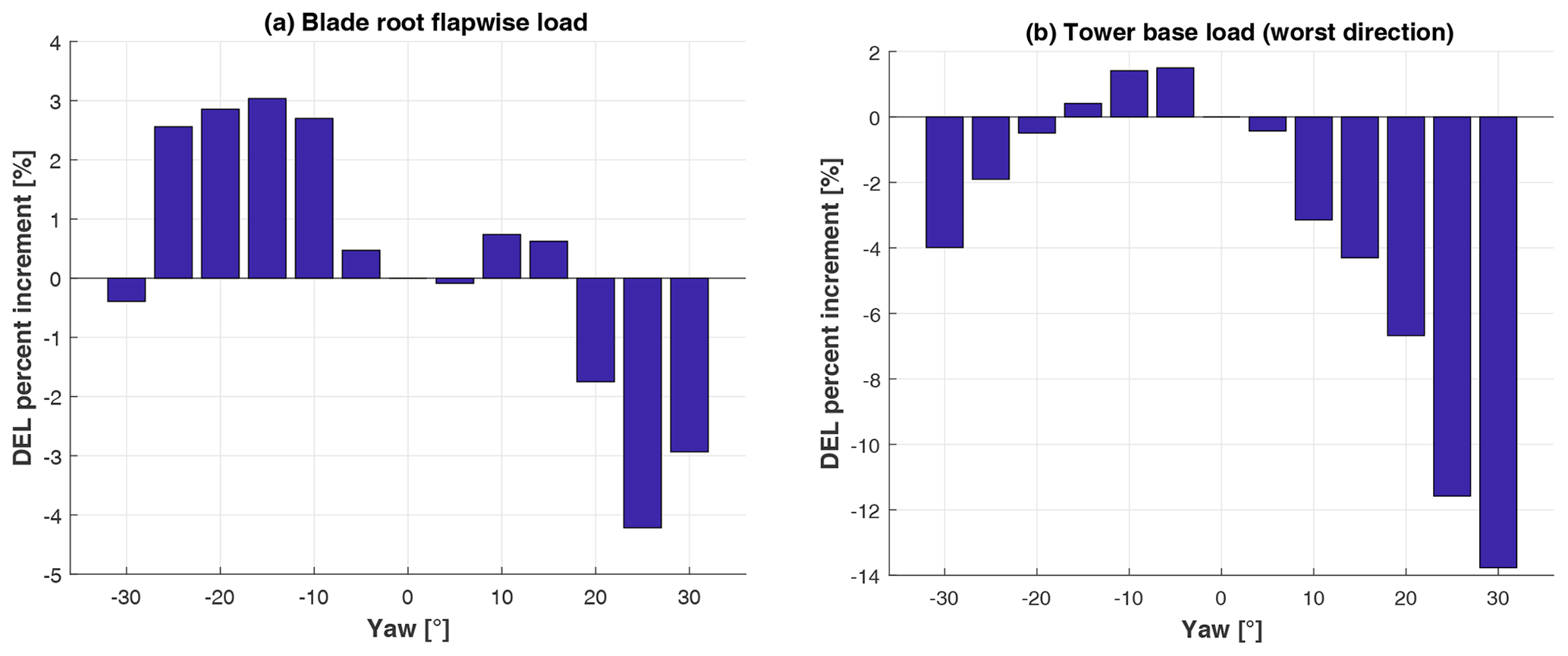
Figure 3Comparison of blade root flap-wise DEL (a) and tower base maximum directional DEL (b).
By looking at these results, one may also conclude that avoiding operating at very high misalignment (i.e., at 30∘) may be beneficial. In fact, up to , the increment of ultimate loads and blade deflections seems essentially limited. The sensitivity analysis shown in this section allows the designer to also estimate the extreme parameters of this wind farm control technique to be applied to already existing wind farms. These limits are defined by the design loads of the single wind turbine: the wind farm operators may apply a specific farm controller as far as the induced loads do not exceed the design ones.
Clearly, this last consideration is not utterly new. In fact, most of the field testings that have been conducted so far (see Fleming et al., 2019) considered only one-sided wake steering. This practice can be useful to cope with the increased loading expected for a specific range of misalignment angles. In a broader sense, one may even think that the conditions, to be avoided because they are considered critical in terms of loading, might comprise complex combinations of speeds, TI levels, yaw angles and shear layers.
4.2 Evaluation of the impact of dynamic induction control
4.2.1 Review of dynamic induction control
Another interesting means of increasing the total wind farm power consists of the so-called dynamic induction control (DIC). Specifically, the upstream wind turbine, when its wake impinges on a downstream machine, modulates the thrust in a periodic way. The modulation can be performed by collectively or cyclically pitching the blades at a specific frequency or by changing the rotor speed. Clearly, the most effective action is to enforce a periodic collective motion (PCM) of the blade pitch angles. The effect of the PCM is to dynamically vary the induction of the rotor and, hence, to increase the mixing level inside the wake. The wake itself results in being energized by such fluctuating induction and recovers in a faster way. DIC was recently studied through computational fluid dynamics (CFD) simulations (Munters and Meyers, 2017, 2018) and validated in a scaled wind tunnel experimental campaign (Frederik et al., 2020b).
The DIC technique studied here is a pure PCM at a single frequency, as described by
where βPCM is the pitch setting imposed by PCM to be summed up to the pitch of the trimmer, APCM is the related amplitude, fPCM is the frequency, t is the time and φPCM is the possible phase.
Despite the limited number of studies devoted to PCM, especially if compared with the amount of literature available about wake redirection technique, it is already possible to highlight some important concepts.
-
PCM seems effective in increasing the total wind farm power output by some percent, as demonstrated by both simulations and wind tunnel experimentation.
-
The increase in wind farm power depends strongly on the amplitude and frequency of the rotor thrust variation.
-
Rather than in terms of frequency f, the effect of the PCM technique is to be viewed in terms of the dimensionless Strouhal number St, defined as
where D is the rotor diameter and U∞ the undisturbed wind velocity.
-
The optimal Strouhal number was found to be 0.25 in CFD simulation (see Munters and Meyers, 2018), whereas in a wind tunnel it was possible to verify significant power increases in a wider range between 0.17 and 0.45 (see Frederik et al., 2020b).
4.2.2 Effect of PCM amplitude and Strouhal number on turbine loading
In order to perform a detailed analysis concerning the ultimate loads, different combinations of amplitude βPCM and Strouhal number St were considered: the range in amplitude was set between 1 and 4∘, whereas the range of the Strouhal number was set between 0.2 and 0.5, according to the findings of an experimental campaign in a wind tunnel (see Frederik et al., 2020b).
It was primarily observed that the phase of the oscillation φPCM is of paramount importance. Consider for example the set of DLCs including extreme conditions. By chance, it is possible that a particular extreme event, like a gust or a fault, occurs at a time in which the PCM control is increasing the collective pitch, thereby reducing the rotor loading. In this case, the peak of the load involved by the extreme event could be smoothed. Conversely, if the extreme event had occurred for decreasing collective pitch angles, the effect of the control would have been that of increasing the load. This is due to the difference between the characteristic time of these extreme events (a few seconds) with respect to the PCM period (tens of seconds). For this reason, in order to find the worst case, i.e., that condition which maximizes the increase in the load, eight different 45∘ spaced phases have been considered. Consequently, the full set of DLCs in Table 1 were simulated, for each couple of amplitude–Strouhal number, eight times, by varying the phase φPCM.
Following the same analyses of Sect. 4.1, it is possible to quantify the effects of this control technique, extracting, for each combination of Strouhal number and pitch amplitude, the maximum loads in the wind turbine sub-components of interest.
Figure 4 shows the ranking of DLC generating the highest peak load (including the related safety factor as reported in Table 1) for blade root flap-wise moment without PCM (a) and with a PCM control characterized by St=0.5 and βPCM=2∘ (b). The ultimate loads are generated in a DLC1.3 (extreme turbulence conditions) at 15 m s−1, and the PCM has the effect of increasing this load by about 6 %.
A different situation is experienced for tower base combined load, reported in Fig. 5. The two subplots are organized as in the previous case. The first place in the ranking is taken by a case in which the PCM is not active, DLC6.2 (b). When the PCM is active (b), the DLC1.4 at Vr increases its position in the ranking, from fourth to third but it is not enough to get to the first position. From this discussion one can conclude that the effect of PCM is null in terms of tower base fore–aft ultimate load.
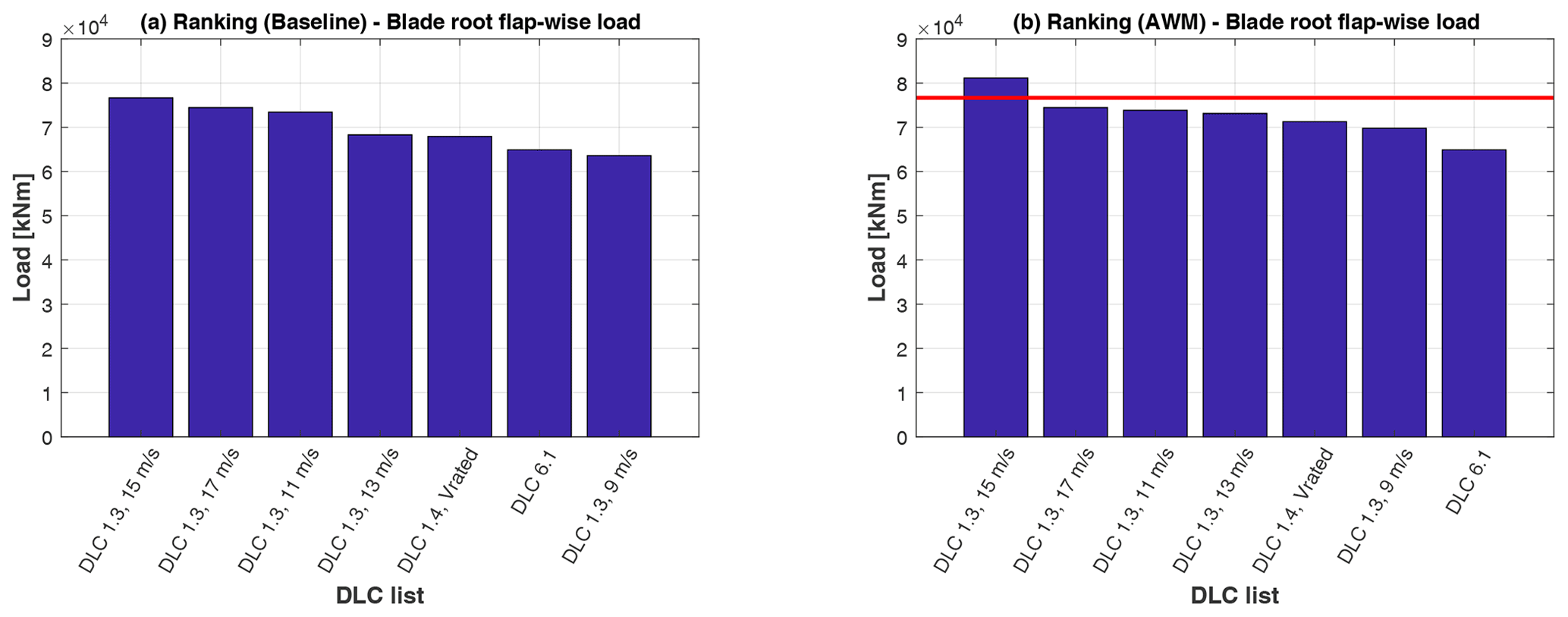
Figure 4Ranking of ultimate loads for blade root flap-wise load for baseline (b) and PCM (a) in the case of St=0.5 and βPCM=2∘. The red line shows the baseline ultimate load.
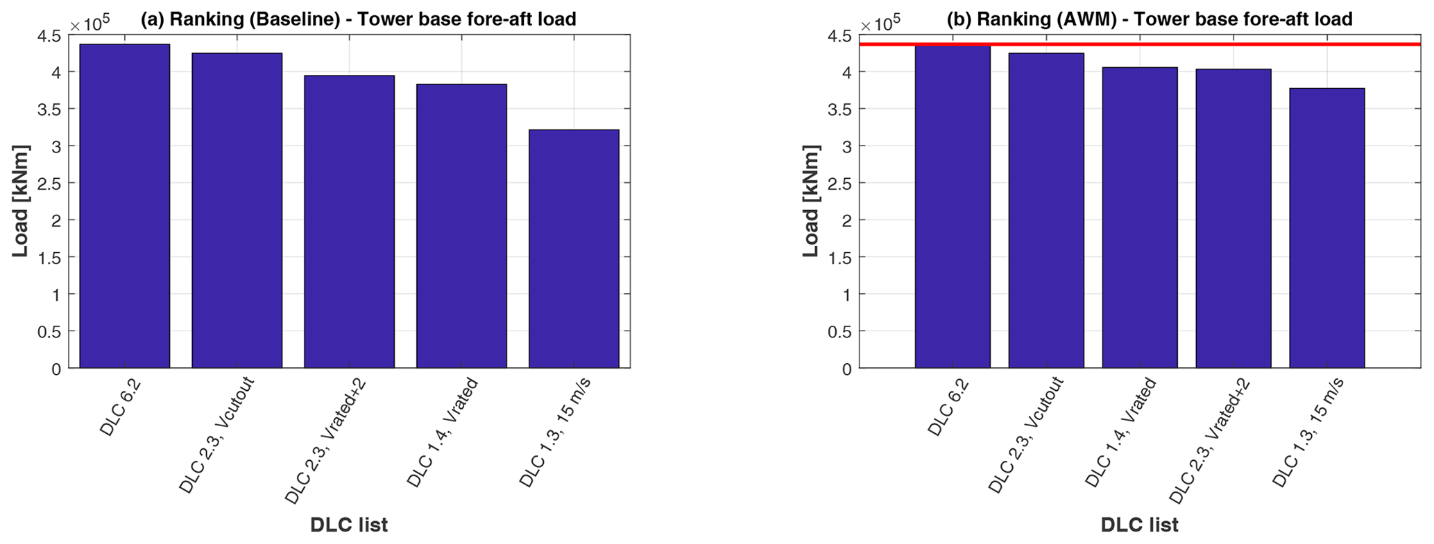
Figure 5Ranking of ultimate loads for blade root flap-wise load for baseline (b) and PCM (a) in the case of St=0.5 and βPCM=2∘. The red line shows the baseline ultimate load.
Figure 6 shows the percentage increment for different combinations of Strouhal number and amplitude for blade root combined moment (a), tower base combined moment (b) and hub combined moment (c). Above each bar, a text indicates the DLC which has generated that maximum load. Significant increases are only associated with blade loads, whereas the hub and tower are not affected by PCM.
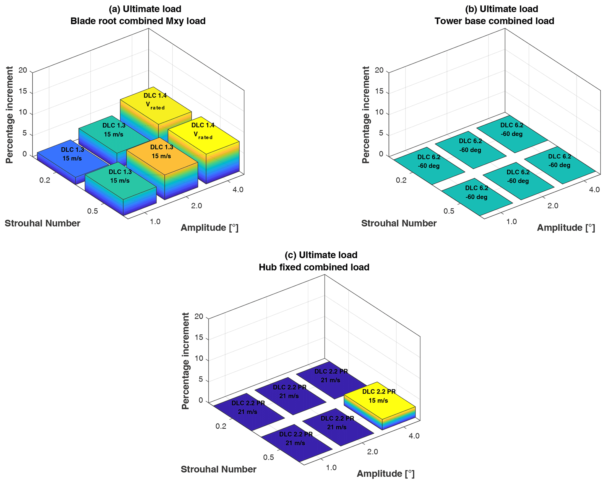
Figure 6Maximum load increases as function of amplitude and Strouhal number. (a) Blade root combined moment. (b) Tower base combined moment. (c) Hub combined moment.
A sensitivity analysis was also conducted so as to compute the variation in maximum blade tip displacement. An increase up to 12 % is measured for βPCM=4∘, as shown in Fig. 7. This indication is extremely important as the maximum tip deflection typically enters as an active constraint into the design of the blade, affecting the thickness of its structural elements, as already seen for the wake redirection technique. If one excludes the highest PCM amplitude (i.e., 4∘), the maximum tip deflection increases only 3 %, which may correspond to a lower impact on blade design.
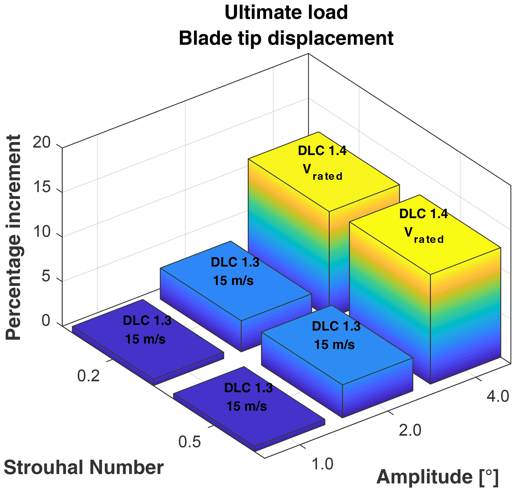
Figure 7Blade tip maximum displacement increase as a function of amplitude and Strouhal number.
From DLC1.2 it is also possible to estimate the actuator duty cycle (ADC) and the impact that PCM may have on it. Especially in the context of PCM, this indicator is important as the pitch ADC may be a driving input for the actuator design. Considering St=0.5 and a full year of operation, the increase in the ADC results equal 77 % and 143 % respectively for βPCM=2 and 4∘. Such numbers appear rather high, but, since they refer to a full year of operation with farm control, they have to be considered as maximum limits. Clearly, a turbine is expected to operate only part of its life following wind farm control inputs. Consequently, the increase in ADC is to be scaled down according to the actual time spent with PCM active.
Finally, Fig. 8 shows the percentage DEL increment for the different combinations of Strouhal number and amplitude for blade root flap-wise (a) and tower base (b). As expected, the highest increases are associated with larger pitch amplitudes and higher Strouhal numbers.
For both blade flap-wise and tower base, the effects are significant and may amount to 20 % and 30 %, respectively, in the worst cases (βPCM=4 and St=0.5). However, if one excludes the highest amplitude limiting the authority of PCM to 2∘, the detrimental effect of PCM in terms of fatigue seems acceptable, being equal to about 10 % for both loads.

Figure 8Weibull weighted DEL increases as a function of amplitude and Strouhal number. (a) Blade root flap-wise moment. (b) Tower base FA moment.
Particular attention should be devoted to the impact of PCM on downstream rotor loading. The change of thrust, in fact, results in a higher in-wake velocity but also creates a low-frequency flow traveling downwind. The impact of such a pulsating flow with downstream machines can be significant in terms of turbine loads and aeroservoelasticity. This particular topic, out of the scope of the present paper, is currently under investigation, and preliminary results are available in Cacciola et al. (2020).
4.3 Comparison between periodic collective motion and wake redirection for the 10 MW INNWIND.EU turbine
To summarize the previous results, Table 2 shows a comparison between the worst cases of WR control and PCM for this 10 MW INNWIND.EU turbine.
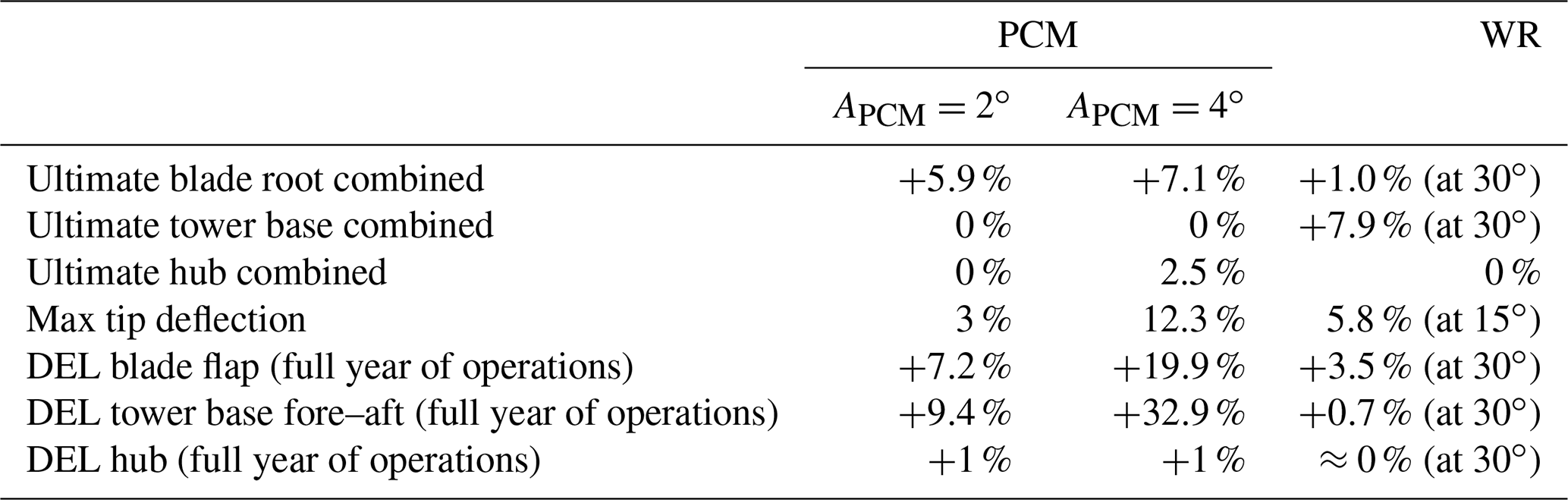
At first sight, PCM control with an amplitude of 4∘ appears to be extremely impactful in terms of ultimate loads and blade deflections, with an increase of more than 10 % in the maximum tip displacement, which could be considered excessive, at least for the present machine whose design is constrained by this value. Excluding the previous case, the impact in terms of fatigue, computed for the first-row wind turbine, appears limited for both control techniques, especially if one considers the assumption that the wind farm control is always active no matter the wind direction and TI. As noted in Zalkind and Pao (2016), in realistic farms, the amount of time spent with non-null inputs coming from the farm control layer can be rather small, yielding an even lower impact on fatigue.
If one considers, on the other hand, only the PCM with an amplitude of 2∘, the impact of PCM and WR becomes comparable, even though the latter seems less impactful, especially for fatigue. In terms of ultimate loads, PCM has a higher impact on blade loads and null on tower, while the opposite happens for blade redirection.
Maximum tip deflection needs special attention as both control techniques entail a significant increase in this quantity. In fact, for a typical glass-fiber blade, the blade-to-tower clearance is often an active constraint of the structural design (Sartori, 2019; Bortolotti et al., 2019; Sartori et al., 2020). Moreover, the load case associated with this ultimate displacement is DLC1.4 (ECD), which is a deterministic wind case. This suggests that an ECD may happen regardless of the turbulence intensity, which justifies, at least for the present study, the initial choice of neglecting a dependency between the TI and the activation of the wind farm controller.
4.4 Evaluation of the impact of wind farm control on rotor design
In the previous sections, different wind farm control strategies have been analyzed with the aim of computing the related effect on wind turbine ultimate loads, as well as on other important design parameters, such as the maximum blade deflection and actuator duty cycles. The performed analyses showed that WR and PCM have an impact on both ultimate loads and maximum tip deflection. The latter, in particular, is a typical driver for blade design, meaning that the maximum blade tip displacement is severely enforced in the design process in order to maintain a suitable clearance between the tip of the blades and the tower.
For this reason, this section on the design can be considered the subsequent step with respect to the previous sensitivity analysis. The goal here is to quantify the possible modifications on the structural design of the blade when the wind farm control is considered. A possible increase in blade mass and turbine cost will be considered concise indicators of the impact of wind farm control on blade design. Since the focus of this study is on the macroscopic impact of wind farm controllers on the design rather than to provide a fully feasible structural layout, we limited our analysis to the aeroelastic optimization loop of Fig. 1.
Moreover, in order to perform a fair comparison where the effects of the sole wind farm control are highlighted, all redesigned rotors should be “optimal”, in the sense that they should all be coming from an equal optimal design process characterized by the very same cost function and constraints, otherwise, it would be impossible to split the effects of the wind farm controller from those of the specific optimization strategy in the final comparison. To this end, the reference INNWIND.EU 10 MW wind turbine is firstly redesigned with Cp-Max following the procedure described in Sect. 3, yielding the “baseline” rotor. Then, the baseline configuration will be updated by the same optimization process but this time including the presence of the wind farm control. The design process of the baseline generated an optimal solution compliant to all optimization constraints, with a structure mildly different with respect to the nominal INNWIND.EU.
Fatigue loads also deserve special attention. It is well known that fatigue loads are critical to the design of a wind turbine and hence are included in the design of the “baseline” rotor, resulting in a blade whose sub-components (especially reinforcements and shear webs) are also sized for fatigue. When one has to also consider the wind farm controllers, as discussed in the previous sections, the fatigue load analysis depends heavily on the wind direction, on the TI and on other factors. Additionally, the sensitivity analyses performed previously for the front-row wind turbine have shown that the impact in terms of fatigue appears limited, even if considering that the wind farm control is always active. In realistic farms, the amount of time spent with non-null inputs coming from the farm control layer can be rather small, yielding an even lower impact on fatigue. For these reasons, in the process of rotor redesign, the fatigue loads, usually included and updated in the Cp-Max environment, are kept frozen and equal to those of the baseline case. Again, this approach allows for better highlighting the impact of the sole ultimate loads due to wind farm controllers on rotor design.
In this section, only the PCM with St=0.5 and will be considered for the redesign. Sartori et al. (2020) report a rotor design comparison which also includes the WR control.
Focusing only on the seems reasonable, since is associated with an excessive increment in the turbine loading status, as reported in Table 2. Moreover, this choice is further justified by the results of a previous experimentation in a wind tunnel with a simple three-turbine farm (Frederik et al., 2020b). In that campaign, the amplitude of the PCM associated with the highest increase in overall farm power output was equal to 1.7∘, a value rather close to that used in the present work.
Obviously, the possible usage of PCM with higher amplitude, if one really needed it, would depend on the balance between the power boost potentially achievable and the detrimental impact on turbine loading.
The structural optimization was then performed by taking into account both the standard DLCs set from Table 1 and all the DLCs in which the turbine is controlled with the PCM. Different phase angles of the PCM were included in the ultimate load and displacement analysis. Once again, the entire set of DLCs was recomputed at each structural iteration to make sure that as the structural design evolves the loads are updated accordingly.
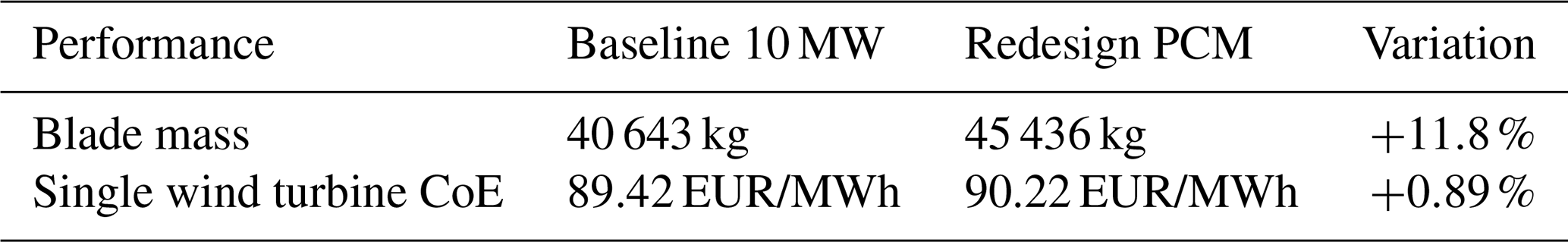
The main results of the redesigned rotor with the PCM are summarized in Table 3. As shown, the introduction of the wind farm controller leads to an overall deterioration of all key performance indicators. It must be stressed, however, that all indicators refer to the individual, front-row turbine as the current release of Cp-Max implements a turbine-specific cost model, and a proper assessment of the impact of the PCM on the cost of energy should be evaluated at the wind farm level.
Table 3Comparison between the KPIs of the Baseline 10 MW and the redesigned rotor.
A complete comparison of the ultimate loads of the Redesign PCM rotor against the baseline 10 MW is also given in Fig. 9, in which all the loads are made dimensionless through the corresponding values of the baseline 10 MW. Here, flp identifies flap-wise, edg is edgewise, trs is torsion, thr is thrust, nod is nodding, yaw is yawing, FA and SS are, respectively, fore–aft and side-side loads, and, finally, the tag cmb identifies multi-directional combined loads. From the diagram it is possible to notice how the blade loads are globally increased by the combination of PCM and higher blade mass. When it comes to the other sub-components, however, the impact is mixed. On the one side, the side–side bending and torsional moments at the tower base are slightly increased, while the fore–aft bending moment is significantly reduced. Based on this limited analysis, then it is possible to conclude that the introduction of the PCM as a wind farm controller would require a redesign of the rotor but, likely, would not affect the structural integrity of hub and tower.
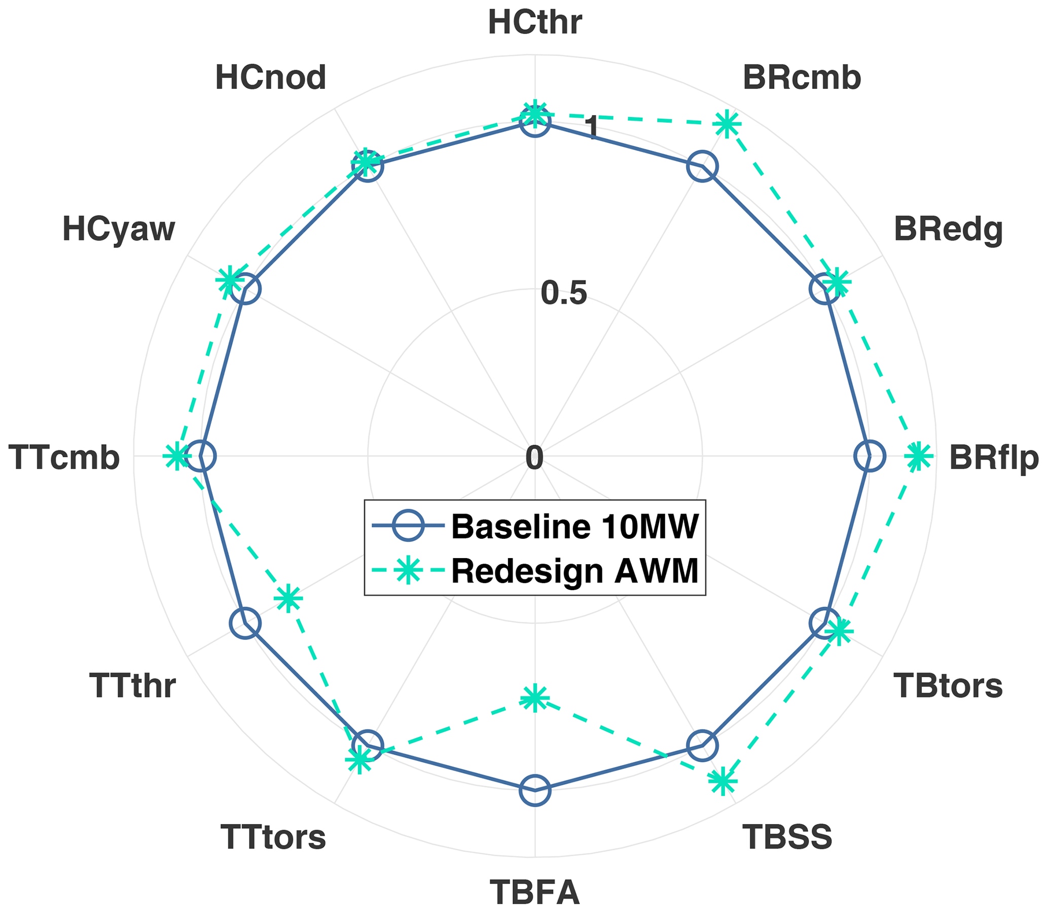
Figure 9Ultimate loads resulting after the redesign process including PCM. BR is blade root, HC is hub center, TT is tower top, and TB is tower base.
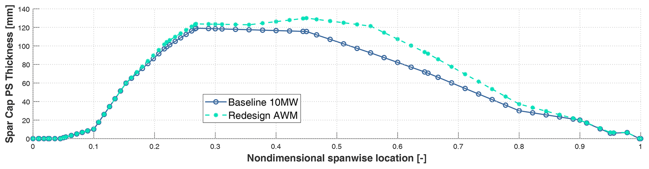
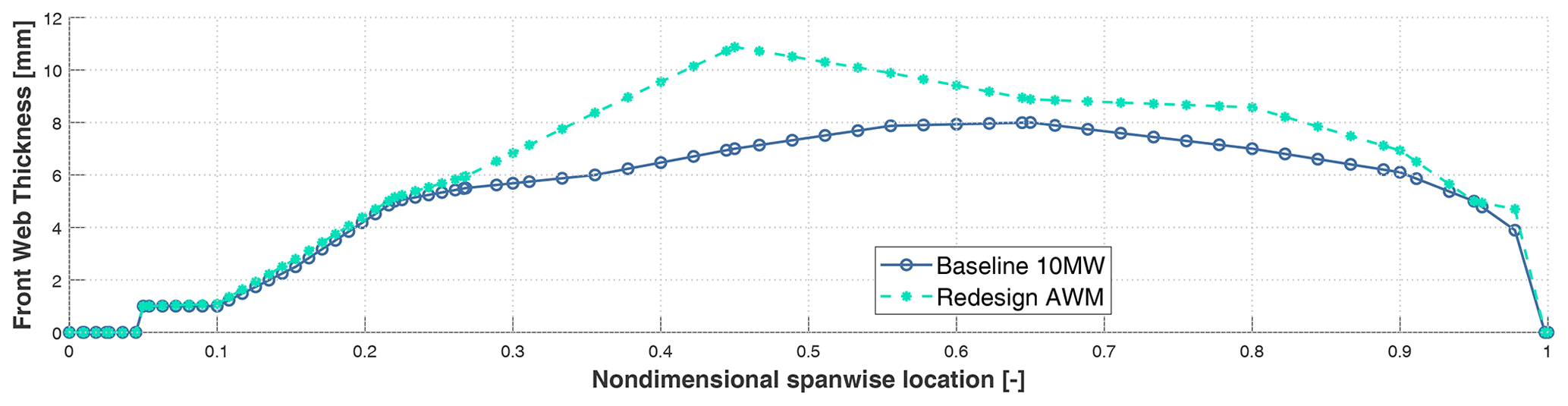
From a structural perspective, as expected, the introduction of the PCM resulted in an about 12 % higher blade mass. This result comes from a combination of the above higher loads and higher displacements introduced by the wind farm controller. Specifically, the increased blade deflection required a heavy redesign of the spar caps in order to avoid the violation of the constraint related to the maximum blade tip displacement. The optimal distribution of spar cap thickness is shown for both the baseline and the redesigned rotor in Fig. 10. It is worth mentioning that, due to the increased flap-wise stiffness, at the end of the optimization, the maximum displacement of the redesigned rotor is almost identical to that of the baseline, and, most importantly, it does not exceed the allowed blade–tower clearance.
Qualitatively similar results have been obtained in the redesign process for the WR case, which was performed in Sartori et al. (2020). The blade redesigned under the WR control was characterized by thicker spars and webs, and, in turn, blade mass increased by 12.6 %. Also in this case, the update of the structural elements was mainly needed to compensate for the increase in the maximum tip deflection, which was experienced in DLC 1.4 for very high misalignment angles (see Fig. 2).
In this paper, a procedure to evaluate the effects of wind farm control techniques on a single wind turbine has been developed. Two different control methods (dynamic induction control and the wake redirection) have been considered and tested on a reference 10 MW wind turbine. The study is conducted by simulating the main design load cases prescribed by the standards with the inclusion of the chosen wind farm control. In this strategy, an explicit dependency of the wind farm control on the turbulence intensity was neglected, whereas the value of turbulence intensity was always defined according to the turbine's class. Although this limits the validity of the conclusions for the turbine under investigation, it allows us to obtain results which are compatible with current standards, and which are not site-specific.
The study has been performed through two steps. At first, the impact of the controls is evaluated in terms of the turbine KPIs (maximum loads, maximum blade tip deflection, AEP, ADC). The study has been conducted as a sensitivity analysis where all indicators are computed as functions of the wind farm control parameters. At this step, we were able to quantify the impact of the control techniques on the performance of an existing turbine and, at the same time, to define the operational limits of the wind farm controller to not exceed the original load spectra. In a second step, a dedicated structural redesign of the rotor has been performed in order to quantify how much the design would have changed if a wind farm control had been considered from the beginning.
From the analyses performed in this work the following conclusions can be derived.
-
The most impactful control seems to be the one based on the dynamic induction, especially if higher amplitudes of the blade pitch angles are considered. However, if the amplitude is maintained below 2∘, the potential increase in fatigue is limited.
-
Tower ultimate loads are particularly affected by wake redirection, with the ECD condition being the most impactful DLC.
-
The blade loads, on the other hand, are mostly affected by dynamic induction control.
-
Both controls lead to an increase in the maximum tip displacements. Since the turbine considered in this study is heavily constrained by tip deflection, this results in a significant mass increase when the rotor is redesigned. It must be noticed that different design concepts (or materials) could result in different sizing loads and, therefore, different impacts on the redesign.
-
The redesign process, due to the abovementioned higher blade deflection, led to an increased rotor mass.
-
In this study, focused on maximum loads, a simplified fatigue load assessment was also made. The impact of these fatigue loads, computed for the first-row wind turbine under the hypothesis the wind farm control is always active, no matter the wind direction and TI, is limited but not negligible. However, in realistic farms, the amount of time spent with non-null inputs coming from the farm control layer can be rather small, yielding an even lower impact on fatigue.
It is important to stress that these findings only apply to the considered 10 MW wind turbine and may be different for other machines. The parametric analyses and the design process have considered only the front-row wind turbine, and, hence, the obtained results cannot be viewed as conclusive unless downstream turbines, together with the wind farm layout and wind rose, are included in the procedure. However, the proposed design provides an important indication on the potential impact of farm controls on the sizing of those turbine components, whose design is driven by ultimate rather than fatigue loads. Moreover, the hypothesis that the wind farm controllers are always active, no matter the wind direction and TI, is surely severe for the fatigue loads, but not for the ultimate ones. In fact, even if the wind farm controls may be activated only for a very short period of time, it is essential to consider that in this time frame extreme events may occur.
Future developments of this work will try to investigate this aspect by considering different turbine classes, design concepts and materials. In addition, it would also be interesting to include in the redesign of the rotor the aerodynamic shape together with the internal structure. Connected to the design, it could also be interesting to consider a different dynamic induction control strategy based on individual pitch control, which entails a lower variation in thrust and which could in turn have a milder impact on blade loading (Frederik et al., 2020a).
In terms of extensions of the present research, the evaluation of the impact of farm control on ultimate and fatigue loads of downstream turbines is certainly an interesting topic, which deserves dedicated analyses with more sophisticated tools than those used in the present work to simulate the wind farm flow, e.g., CFD or dynamic wake models (Cacciola et al., 2020).
Additionally, the analyses conducted in this work considered that a possible failure of wind farm control laws does not significantly affect the ultimate loads of the single wind turbines, because the turbine controller has priority over the farm one. Clearly, such an assumption, reasonable for the goal of this paper, would deserve a dedicated treatment.
Another important direction for future works deals with the assessment of the economic impact of wind farm control at the wind-farm level. To this end, specific studies will be done to consider not only the impact of the chosen wind farm control on the turbine loads but also the beneficial effects that the chosen wind farm control has on the wind farm power production and, possibly, on its cost of energy.
The data and the numerical tools used in this analysis may be obtained by contacting the corresponding author.
All authors provided fundamental input to this research work through discussions, feedback and analyses of the state of the art. AC and SC conducted the sensitivity analysis with the WR control, SC conducted the sensitivity analysis with the PCM, LS performed the structural design, and AC developed the main idea behind this work and supervised the research activities. SC, AC and LS wrote the manuscript.
The contact author has declared that neither they nor their co-authors have any competing interests.
Publisher’s note: Copernicus Publications remains neutral with regard to jurisdictional claims in published maps and institutional affiliations.
The authors want to thank the former student Paride De Fidelibus for his help in the model setup for the WR control.
This research has been partially supported by the CL-Windcon project, which receives funding from the European Union Horizon 2020 research and innovation program (grant no. 727477).
This paper was edited by Carlo L. Bottasso and reviewed by Vasilis A. Riziotis and three anonymous referees.
Annoni, J., Gebraad, P. M., Scholbrock, A. K., Fleming, P., and v. Wingerden, J.-W.: Analysis of axial-induction-based wind plant control using an engineering and a high-order wind plant model, Wind Energy, 19, 1135–1150, 2016. a
Bak, C., Zahle, F., Bitsche, R., Kim, T., Yde, A., Henriksen, L. C., Hansen, M. H., Blasques, J. P. A. A., Gaunaa, M., and Natarajan, A.: The DTU 10-MW Reference Wind Turbine, available at: https://backend.orbit.dtu.dk/ws/portalfiles/portal/55645274/The_DTU_10MW_Reference_Turbine_Christian_Bak.pdf (last access: 29 October 2021), 2013. a, b
Bauchau, O. A.: Flexible Multibody Dynamics, 1st edn., Solid Mechanics and Its Applications, 176, Springer, Netherlands, 978-94-007-0335-3, 2011. a
Boorsma, K.: Power and loads forwind turbines in yawed conditions – Analysis of field measurements and aerodynamic predictions, ECN-E–12-047, Energy reserach Center of the Netherlands (ECN), Tech. Rep., available at: https://publicaties.ecn.nl/PdfFetch.aspx?nr=ECN-E--12-047 (last access: 29 October 2021), 2012. a, b
Bortolotti, P., Bottasso, C. L., and Croce, A.: Combined preliminary–detailed design of wind turbines, Wind Energy Sci., 1, 71–88, https://doi.org/10.5194/wes-1-71-2016, 2016. a
Bortolotti, P., Bottasso, C. L., Croce, A., and Sartori, L.: Integration of multiple passive load mitigation technologies by automated design optimization – The case study of a medium-size onshore wind turbine, Wind Energy, 22, 65–79, https://doi.org/10.1002/we.2270, 2019. a
Bossanyi, E.: Combining induction control and wake steering for wind farm energy and fatigue loads optimisation, J. Phys. Conf. Ser., 1037, 032011, https://doi.org/10.1088/1742-6596/1037/3/032011, 2018. a
Bottasso, C. L. and Croce, A.: Cp-Lambda user manual, Dipartimento di Scienze e Tecnologie Aerospaziali, Politecnico di Milano, Milano, Italy, Tech. Rep., available at: https://www.aero.polimi.it/index.php?id=304&uid=22&L=0 (last access: 29 October 2021), 2009–2018. a
Bottasso, C. L., Croce, A., Savini, B., Sirchi, W., and Trainelli, L.: Aero-servo-elastic modeling and control of wind turbines using finite element multibody procedures, Multibody Syst. Dyn., 16, 291–308, 2006. a
Cacciola, S., Bertozzi, A., Sartori, L., and Croce, A.: On the dynamic response of a pitch/torque controlled wind turbine in a pulsating dynamic wake, J. Phys. Conf. Ser., 1618, 062033, https://doi.org/10.1088/1742-6596/1618/6/062033, 2020. a, b
Cardaun, M., Roscher, B., Schelenz, R., and Jacobs, G.: Analysis of Wind-Turbine Main Bearing Loads Due to Constant Yaw Misalignments over a 20 Years Timespan, Energies, 12, 1768, https://doi.org/10.3390/en12091768, 2019. a
CL-Windcon: Closed Loop Wind Farm Control, available at: http://www.clwindcon.eu/ (last access: 29 October 2021), 2016–2019. a
CL-Windcon deliverable D4.7: Closed Loop Wind Farm Control – Review on Standards and Guidelines, Tech. Rep., available at: http://www.clwindcon.eu/public-deliverables/ (last access: 29 October 2021), 2019. a
Damiani, R., Dana, S., Annoni, J., Fleming, P., Roadman, J., van Dam, J., and Dykes, K.: Assessment of wind turbine component loads under yaw-offset conditions, Wind Energy Sci., 3, 173–189, https://doi.org/10.5194/wes-3-173-2018, 2018. a
Ennis, B. L., White, J. R., and Paquette, J. A.: Wind turbine blade load characterization under yaw offset at the SWiFT facility, J. Phys. Conf. Ser., 1037, 052001, https://doi.org/10.1088/1742-6596/1037/5/052001, 2018. a, b
FarmConners deliverable D2.1: Position paper on certification, standardisation, and other regulatory issues of Wind Farm Control, Tech. Rep., available at: https://www.windfarmcontrol.info/ (last access: 29 October 2021), 2020. a
Fingersh, L., Hand, M., and Laxson, A.: Wind Turbine Design Cost and Scaling Model, National Renewable Energy Laboratory, Tech. Rep. NREL/TP-500-40566, available at: https://www.nrel.gov/docs/fy07osti/40566.pdf (last access: 20 December 2021), 2006. a
Fleming, P., King, J., Dykes, K., Simley, E., Roadman, J., Scholbrock, A., Murphy, P., Lundquist, J. K., Moriarty, P., Fleming, K., van Dam, J., Bay, C., Mudafort, R., Lopez, H., Skopek, J., Scott, M., Ryan, B., Guernsey, C., and Brake, D.: Initial results from a field campaign of wake steering applied at a commercial wind farm – Part 1, Wind Energy Sci., 4, 273–285, https://doi.org/10.5194/wes-4-273-2019, 2019. a, b, c
Frandsen, S. T.: Turbulence and turbulence-generated structural loading in wind turbine clusters, Forskningscenter Risø, Denmark, Tech. Rep. Risø-R no. 1188, available at: https://backend.orbit.dtu.dk/ws/portalfiles/portal/12674798/ris_r_1188.pdf (last access: 29 October 2021), 2007. a
Frederik, J. A., Doekemeijer, B. M., Mulders, S. P., and van Wingerden, J.-W.: The helix approach: Using dynamic individual pitch control to enhance wake mixing in wind farms, Wind Energy, 23, 1739–1751, https://doi.org/10.1002/we.2513, 2020a. a
Frederik, J. A., Weber, R., Cacciola, S., Campagnolo, F., Croce, A., Bottasso, C., and van Wingerden, J.-W.: Periodic dynamic induction control of wind farms: proving the potential in simulations and wind tunnel experiments, Wind Energy Sci., 5, 245–257, https://doi.org/10.5194/wes-5-245-2020, 2020b. a, b, c, d, e
Gebraad, P., Thomas, J. J., Ning, A., Fleming, P., and Dykes, K.: Maximization of the annual energy production of wind power plants by optimization of layout and yaw-based wake control, Wind Energy, 20, 97–107, 2017. a, b
Gebraad, P. M. O., Teeuwisse, F. W., van Wingerden, J. W., Fleming, P. A., Ruben, S. D., Marden, J. R., and Pao, L. Y.: Wind plant power optimization through yaw control using a parametric model for wake effects – a CFD simulation study, Wind Energy, 19, 95–114, https://doi.org/10.1002/we.1822, 2016. a, b
IEC: Wind Turbines – Part 1: Design requirements, 3rd edn., The International Electrotechnical Commission, Tech. Rep. International Standard 61400-1:2005, 2005. a, b, c, d
IEC: Wind Energy generation systems – Part 1: Design requirements, 4th edn., The International Electrotechnical Commission, Tech. Rep. International Standard 61400-1:2019, 2019. a
IK4 Research Alliance: IK4 Baseline controller for INNWIND 10 MW wind turbine, GitHub, available at: https://github.com/ielorza/OpenDiscon (last access:29 October 2021), 2016. a
Kanev, S., Savenije, F., and Engels, W.: Active wake control: An approach to optimize the lifetime operation of wind farms, Wind Energy, 21, 488–501, https://doi.org/10.1002/we.2173, 2018. a, b
Knudsen, T., Bak, T., and Svenstrup, M.: Survey of wind farm control—power and fatigue optimization, Wind Energy, 18, 1333–1351, https://doi.org/10.1002/we.1760, 2015. a
Mendez Reyes, H., Kanev, S., Doekemeijer, B., and van Wingerden, J.-W.: Validation of a lookup-table approach to modeling turbine fatigue loads in wind farms under active wake control, Wind Energy Sci., 4, 549–561, https://doi.org/10.5194/wes-4-549-2019, 2019. a, b
Munters, W. and Meyers, G.: An optimal control framework for dynamic induction control of wind farms and their interaction with the atmospheric boundary layer, Philos. T. R. Soc. A, 375, 20160 100–1–19, 2017. a, b
Munters, W. and Meyers, G.: Towards practical dynamic induction control of wind farms: analysis of optimally controlled wind-farm boundary layers and sinusoidal induction control of first-row turbines, Wind Energy Sci., 3, 409–425, 2018. a, b, c
Riboldi, C. E. D.: Advanced control laws for variable-speed wind turbines and supporting enabling technologies, PhD thesis, Politecnico di Milano, Italy, available at: https://www.politesi.polimi.it/bitstream/10589/56887/1/2012_03_PhD_Riboldi.pdf (last access: 23 December 2021), 2012. a
Sartori, L.: System design of lightweight wind turbine rotors, PhD thesis, Politecnico di Milano, Italy, available at: https://www.politesi.polimi.it/bitstream/10589/144667/3/2019_01_PhD_Sartori_b.pdf (last access: 29 October 2021), 2019. a, b
Sartori, L., De Fidelibus, P., Cacciola, S., and Croce, A.: Wind turbine rotor design under wind farm control laws, J. Phys. Conf. Ser., 1618, 042027, https://doi.org/10.1088/1742-6596/1618/4/042027, 2020. a, b, c
Urbán, A. M., Larsen, T. J., Larsen, G. C., Held, D. P., Dellwik, E., and Verelst, D.: Optimal yaw strategy for optimized power and load in various wake situations, J. Phys. Conf. Ser., 1102, 012019, https://doi.org/10.1088/1742-6596/1102/1/012019, 2018. a
White, J., Brandon, E., and Herges, T. G.: Estimation of Rotor Loads Due to Wake Steering, in: Wind Energy Symposium 2018, Kissimmee, Florida, USA, 8–12 January 2018, https://doi.org/10.2514/6.2018-1730, 2018. a
Zalkind, D. S. and Pao, L. Y.: The fatigue loading effects of yaw control for wind plants, in: 2016 American Control Conference (ACC), Boston, MA, USA, 6–8 July 2016, 537–542, https://doi.org/10.1109/ACC.2016.7524969, 2016. a, b
Ziegler, L., Gonzalez, E., Rubert, T., Smolka, U., and Melero, J. J.: Lifetime extension of onshore wind turbines: A review covering Germany, Spain, Denmark, and the UK, Renew. Sust. Energ. Rev., 82, 1261–1271, https://doi.org/10.1016/j.rser.2017.09.100, 2018. a
- Abstract
- Introduction and motivation
- Methodology
- Analysis and design framework
- Sensitivity analysis about the effects of wind farm control on turbine level
- Conclusion and outlook
- Code and data availability
- Author contributions
- Competing interests
- Disclaimer
- Acknowledgements
- Financial support
- Review statement
- References