
the Creative Commons Attribution 4.0 License.
the Creative Commons Attribution 4.0 License.
 | 12 Aug 2026
A multi-parametric composite approach for the optimization of wind turbine blades using Double-Double laminates
Gustavo Nunes Ribeiro
Sascha Dähne
Lennart Tönjes
David Zerbst
Christian Hühne
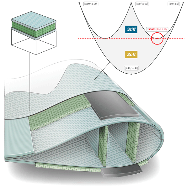
As wind turbines scale to meet growing energy demands, blade structures face increasingly demanding performance requirements. This work addresses this challenge by extending the design space of composite blades through the substitution of traditional triaxial laminates with Double-Double (DD) laminates. While triaxial laminates are widely used due to their convenient lay-up and manufacturability, they are rarely scrutinized in literature and often lead to suboptimal structural performance. To enable this substitution, a multi-parametric composite modeling approach is developed and integrated into a gradient-based optimization framework. This architecture enables the coexistence of discrete and continuous laminate formulations within a single panel, allowing for detailed, skin-wise optimization of sandwich structures. The approach is applied to a modified blade design of the IEA-15-240 reference wind turbine. Results demonstrate that DD laminates provide a more effective design, resulting in significant mass savings in the shell structure.
- Article
(9266 KB) - Full-text XML
- BibTeX
- EndNote


As wind turbines evolve to support greater energy supply, scaling rotor size has become essential to maximizing power output. The annual energy production (AEP) increases proportionally to the square of the blade radius (Gasch and Twele, 2012), whereas blade mass scales to the power of around 2.4 with the blade radius (Rosemeier and Krimmer, 2022). This imbalance creates a structural challenge: increasing blade length raises the aerodynamic potential but also increases mass and loads.
Composite materials have been fundamental in counteracting these trends. Beyond a high strength-to-weight ratio, their mechanical response can be tailored to the dominant load paths through ply orientation and stacking sequence. Unlike isotropic metallic alloys, fiber-reinforced laminates enable control of directional stiffness and coupling, improving structural efficiency. As a result, modern blades rely predominantly on composites, which account for approximately 93 % of their structural weight (Liu and Barlow, 2017).
Although reinforced plastics offer significant potential for weight reduction, they also introduce challenges in design, analysis, optimization, and manufacture. Beyond selecting the fiber composition and matrix material, the lay-up configuration must be defined, including ply angles, stacking order, and thickness distributions.
In practice, blades are often designed using predefined laminate families, which are then treated as homogenized single layers for design and analysis. Following this practice, the blade designs of International Energy Agency (IEA) reference wind turbines (RWTs) make use of a set of laminates with pre-established angles and thicknesses (fabrics). This is also motivated by manufacturability because more complex lay-ups significantly increase cost, defect sensitivity, and tapering effort. Standardized families, particularly when produced with fabrics, reduce variability and simplify both production and structural modeling.
Aligned with industry trends and the demand for a new baseline in the 10–20 MW range, the IEA Wind TCP Task 37 introduced the IEA 15 MW RWT in March 2020 – an offshore turbine intended to push the state of the art (Gaertner et al., 2020). To accommodate higher power capture, the blade length and mass were scaled to 117 m and 65 t, respectively. Structurally, the design follows a traditional layout with two main spars and spar caps, complemented by shear webs that extend from 10 % to 95 % of the blade span. The triaxial glass laminate covers most of the structure, while the shear webs are reinforced with biaxial glass fibers. The internal volume, apart from key load-bearing components, is filled with medium-density foam in a sandwich configuration to limit weight. The trailing and leading edges feature a uniaxial glass laminate, while the spar caps employ uniaxial carbon laminate as the core material. The structural concept is shown in Fig. 1.
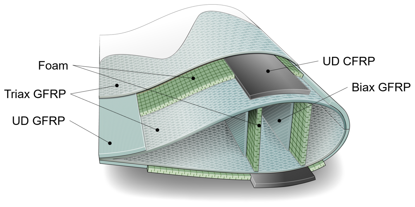
Figure 1IEA 15 MW structural concept. Source: Werthen et al. (2023).
Beyond the specific architecture of the IEA 15 MW, the selection of laminate materials reflects a consistent trend across successive reference models – dominated by triaxial laminate applications. Early designs, such as the NREL 1.5, 3, and 5 MW reference wind turbines (Rinker and Dykes, 2018), extensively employed triaxial glass laminates, wrapping both the shell and spar webs. More recent baselines, including the DTU 10 MW (Bak et al., 2013), IEA 10 MW (Bortolotti et al., 2019), IEA 15 MW (Gaertner et al., 2020), and IEA 22 MW (Zahle et al., 2024), retain triaxial laminates primarily on the shell, while the spar webs employ biaxial laminates. Despite this evolution, triaxial materials still represent a substantial share of the overall blade mass.
A typical triaxial lay-up follows the sequence , comprising roughly 50 % unidirectional (0°) and 50 % off-axis (±45°) plies (Camarena et al., 2022). This configuration is attractive for its balanced response under general loading, providing in-plane shear resistance, bending stiffness, and improved buckling performance (Castro, 2018). However, its near-generic character limits the tailoring of stiffness and directional coupling. For this reason, triaxial laminates are often adopted in less optimized industrial contexts due to their simplicity and generality (Samborsky and Mandell, 1996).
Building on the reference models, several studies explored blade optimization under different design settings. Sjølund and Lund (2018) optimized only the thickness of a variety of layers on a 73.5 m blade and achieved a 19.4 % mass reduction. Serafeim et al. (2022) tailored spar-cap stiffness by rotating the unidirectional (UD) fibers, obtaining a 5.8° off-axis solution and an 8.3 % reduction on the DTU 10 MW blade. Hayat et al. (2022) conducted material and thickness optimization of the spar caps (glass, hybrid, carbon), reporting a reduction of up to 26.4 %, consistently with the spanwise strategy adopted in the IEA 15 MW baseline. Scott et al. (2022) optimized the IEA 15 MW using thickness laws, material mix, and spar-cap position; however, under frozen loads, they required a 34.7 % mass increase to recover stability. Extending stiffness tailoring, Couto et al. (2023) used region-wise laminate optimization with discrete angle sets but remained constrained by the limited orientations.
The vast, discrete design space of composite laminates intrinsically motivates simplifications in their description and design. Most commonly, ply orientations are fixed, and only thickness is scaled (e.g., Sjølund and Lund, 2018; Hayat et al., 2022; Scott et al., 2022); in other cases, the space is restricted to a small discrete set of angles, reducing tailoring margin (e.g., Couto et al., 2023). A similar pattern appears in aeronautics, where quad-laminates – an extension of Triax with an added 90° ply – are widely used; they deliver behavior closer to metallic alloys but at the cost of a more complex design and optimization pipeline (Tsai, 2021).
To address these limitations, Tsai (2021) introduced the Double-Double (DD) laminate class. A DD is defined by two angles (Φ,Ψ) forming the four-ply building block repeated r times. This yields a continuous, balanced parametrization with straightforward homogenization, making design and optimization less complex. A key advantage is tapering: building blocks can be dropped to transition between neighboring panels without symmetry constraints, a common practice in the blade industry, thereby not introducing any complexity into the current standpoint. From a manufacturing standpoint, Kappel and Tsai (2024) demonstrated DD laminates using prepregs and vacuum infusion, predominantly prepregs with off-the-shelf materials, which can be transferred to wind turbine blade production with new types of fabrics.
Almeida et al. (2025) surveyed the use of DD laminates across applications and discussed their implications. Notably, Garofano et al. (2023) compared DD laminates with conventional lay-ups in fuselage structures and reported a 34 % weight reduction. Riccio et al. (2024) conducted this comparison for composite aeronautical components and reported mass savings of up to 50 %. Zerbst et al. (2025) integrated a DD plate formulation into a gradient-based optimization environment for composite structures called lightworks (Dähne et al., 2024) and validated it on a wing-box case. These results highlight the weight-saving potential of DD laminates across aerospace structures and their initial integration into lightworks.
Extending this capability to wind turbine blades requires higher modeling fidelity as blade panels are typically sandwich structures composed of multiple materials through the thickness. In practice, outer face sheets may follow a continuous DD description, whereas cores remain discrete laminates. Representing such combinations requires a clear parametrization strategy, in which each constituent material defines its own design variables, while consistently contributing to the overall panel response. To support this requirement, a modular and multi-parametric plate formulation is introduced. It allows for the independent parametrization of sub-components and their integration into a unified structural layer. This approach accommodates both continuous and discrete laminates within the same stack and enables replacement of conventional triaxial skins with DD laminates. This way, the design space is expanded towards more adaptable stiffness behavior.
1.1 Objectives
In light of the above, the central objective of this study is to enlarge the design space for sandwich composite panels in the context of structural mass optimization for large wind turbine blades. This is achieved by introducing DD laminates in place of the predefined stiffness-fixed triaxial laminates.
To make this substitution viable within sandwich panels, a multi-parametric composite approach is introduced and implemented in the lightworks optimization environment. The approach models sandwich structures as modular assemblies of independently parameterized sub-composites, enabling materials with different structural foundations, such as layer-based and continuous formulations, to coexist across the panel thickness.
This work naturally follows as a continuation of the study by Werthen et al. (2023), who employed lightworks for large-scale blade optimization using a simplified sandwich representation, in which each component (e.g., a triaxial laminate) was modeled as a single equivalent layer in the stack. In contrast, the present approach expands the formulation to incorporate DD laminates, which is demonstrated on the CRC-15-240 blade, an in-house modified version of the IEA-15-240 reference wind turbine. This constitutes the first application of DD laminates in wind turbine blade design and represents a step forward in advancing composite optimization for the wind industry.
1.2 Structure of the paper
The development of this work is organized into three consecutive phases, each addressing a distinct layer of the proposed methodology. All implementations are subjected to verification and testing, with feedback loops guiding refinements at each stage.
The first phase focuses on DD laminates as replacements for the Triax. It includes reviewing the mechanical role and limitations of triaxial laminates, characterizing the stiffness and failure behavior of DD configurations, performing parametric load studies, and implementing a restricted “hard” variant with fixed Φ = 0° for intermediate optimization tests.
The second phase extends the lightworks structural model to support multi-parametric composites. This involves developing a class to handle modular stacking, implementing algorithms for stiffness assembly and load distribution through the thickness, and integrating the formulation into the structural and optimization pipeline.
The third phase applies the methodology to the CRC-15-240 blade, demonstrating the practical use of the multi-parametric framework and DD laminates in large-scale optimization. This involves adapting auxiliary tools to the framework and analyzing outcomes in terms of mass reduction, design space expansion, and material property distribution along the span.
The subsequent sections of this study are organized as follows. Section 2 investigates DD laminates in comparison to triaxial laminates. Section 3 introduces the multi-parametric approach and demonstrates it through a single-panel case. Section 4 applies the methodology to the CRC-15-240 blade, detailing the optimization setup. Section 5 presents a comparative assessment of results. Finally, Sect. 6 summarizes the key findings.
The DD laminate concept, introduced by Tsai (2021), represents a significant advancement in the efficient design of composite structures. Based entirely on the classical laminate theory (CLT), its formulation requires no additional assumptions and, notably, removes the need for mid-plane symmetry, traditionally imposed to avoid bending–extension coupling, simplifying design and manufacturing constraints.
A typical DD laminate is composed of repeated building blocks (BBs), each containing four plies arranged in two balanced angle pairs of Φ and Ψ. Among the possible stacking options, the configuration has been shown to yield superior homogenization characteristics (Tsai, 2021) and is therefore adopted throughout this work. The complete laminate is formed by repeating this block r times through the thickness, resulting in the configuration , where the subscript T denotes the total stack, following the Nettles convention (Nettles, 1994).
2.1 Homogenization
The main advantage of DD laminates lies in their potential for homogenization: as the number of building blocks increases, the bending and extensional stiffness matrices ([D] and [A]) approach proportionality, while the coupling matrix ([B]) tends towards zero. The resulting structure exhibits a layer-position-independent response with minimal coupling between in-plane and out-of-plane behaviors.
As reported in Zerbst et al. (2025), the normalized matrices exhibit characteristic dependencies on r. These trends indicate that, with increasing r, the off-diagonal terms of [B*] decay as , while specific coupling terms in [D*] vanish at a rate of . To formalize this, Tsai (2021) elaborated two conditions to be met for assumed homogenization:
where α is a prescribed fraction of the Tsai modulus, defined as the trace of the ply stiffness matrix [Q] (TSAI = Tr[Q]). Acting as a threshold to define acceptable levels of coupling and stiffness mismatch, Tsai (2021) recommends α = 0.02.
Once these conditions are met, the laminate behavior can be approximated using only the extensional stiffness matrix [A], and the bending stiffness [D] can be derived as follows:
where denotes the transformed reduced stiffness matrix of the kth ply in the building block, dependent on ±Φ or ±Ψ.
Figure 2 shows that Tsai's homogenization criterion is satisfied for both the Triax and two DD laminates at four repetitions r. Since a DD laminate is defined by two angle pairs , a Triax fabric can be interpreted as a DD laminate with as a single repetition r. The criterion depends solely on the number of repetitions and not on individual ply thickness as the [ABD*] matrices are normalized by the laminate thickness tlam.
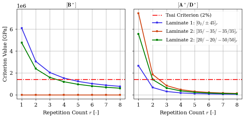
Figure 2Homogenization criterion values for Triax and two DD laminates as a function of repetition count r.
2.2 Design space
According to Tsai and Melo (2015), any laminate can be described through lamination parameters: a continuous stiffness representation grounded in invariant theory. To characterize the design space of DD laminates relative to conventional triaxial configurations, their formulation is briefly recalled.
The general formulation of the lamination parameters can be expressed as follows, in accordance with Zerbst et al. (2025):
where zk is the distance from the kth ply to the laminate mid-plane, and Wx denotes trigonometric functions of the ply angle θ.
For a homogenized DD laminate, this formulation is simplified considerably. All coupling-related lamination parameters vanish, and, due to the proportional nature of [A] and [D], the bending parameters equal the extensional ones (). The resulting formulation is thus reduced to four unique values, among which only and (and their bending counterparts) vary with the fiber angles Φ and Ψ:
Thus, the entire design space of a DD laminate can be visualized in the – plane, where each admissible combination of the angle pair {Φ,Ψ} maps to a specific point. Figure 3 illustrates the full DD design space, as mathematically described in Zhao et al. (2023).
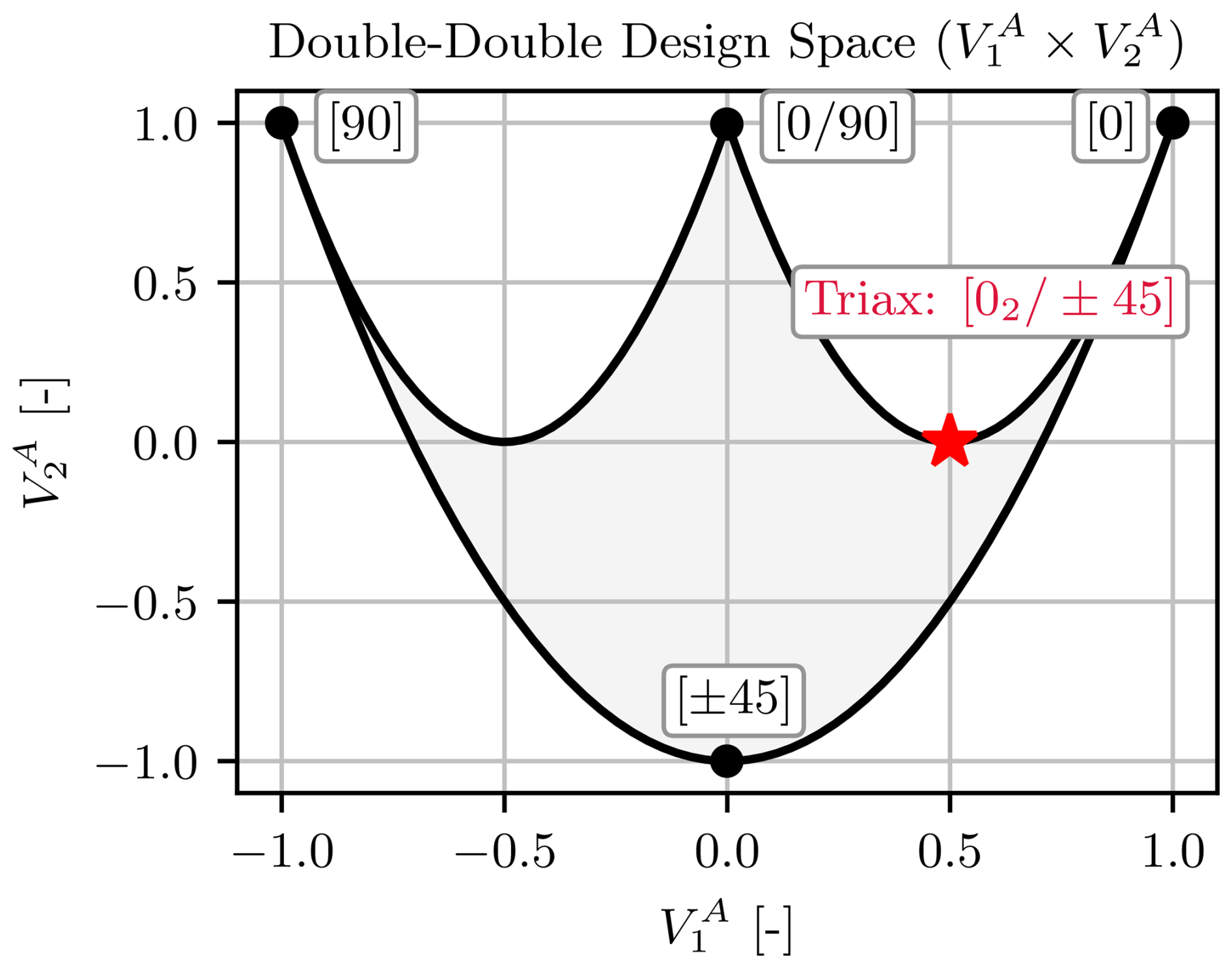
An important aspect to highlight is the role of the lamination parameter . Laminates with ≥ 0 are classified as hard laminates due to their greater resistance to normal stresses, whereas those with < 0 are called soft laminates, exhibiting improved shear and buckling performance.
A typical triaxial laminate can be interpreted as a particular case of the DD configuration, though with a stacking arrangement that is not optimal for homogenization (Tsai, 2021). Owing to its position along the vertical axis of the design space, the triaxial laminate lies within the hard region. Nevertheless, the inclusion of ±45° plies determines a hybrid character, improving its shear and buckling resistance. Despite their practicality, triaxial laminates are ill-suited to optimization: they are fixed at a single point in the lamination–parameter space, enforcing a predefined normal–shear compromise. As a result, their capacity to adapt to specific load cases is limited unless the optimal solution coincidentally aligns with the same fiber orientations.
2.3 Strength criterion
For discrete laminates, strength evaluations are typically performed at the ply level (i.e., Tsai-Wu criterion). However, when employing a continuous homogenized formulation, ply-level evaluation becomes inconsistent with the design representation. In this context, a laminate-level failure criterion is essential to maintain continuous formulation without lay-up reconstruction.
One laminate-level alternative is the strain-based omni-envelope criterion proposed by Tsai and Melo (2015). This method is derived from the classical quadratic failure criterion in stress space and is reformulated in strain space. The general form of the failure condition is expressed as follows:
where Hij and Hi are material-dependent coefficients derived from strain invariants. These coefficients depend on the stiffness matrix and ply orientation, and their derivation is detailed in Kappel (2023).
The omni-envelope extends the ply-level criterion by superimposing the strain space envelopes of unidirectional plies across all fiber orientations present in the laminate, following the Tsai-Wu criterion (Kappel, 2022). The result is a global strain envelope that represents the union of all individual failure surfaces. Zerbst et al. (2025) discuss its use for DD laminates using lightworks.
2.4 Design space exploration under in-plane loads
Under distinct loading conditions, DD laminates adjust their angles to optimize the response in relation to a specific objective (e.g., mass), exploring the full design space capacity previously shown in Fig. 3. This analysis considers only strength constraints, provided by the omni-envelope criterion, and disregards any stability assessment. The focus remains exclusively on material-level response.
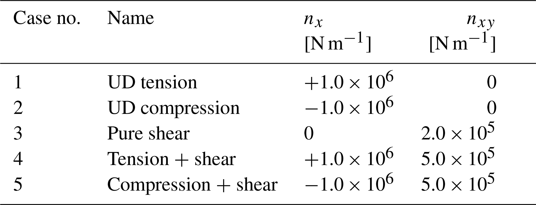
The exploration includes pure and combined loading conditions involving uniaxial (nx) and shear loads (nxy): a scenario similar to the wind turbine blade application explored in this study. The load cases are summarized in Table 1.
Table 1In-plane load combinations used for design space exploration.
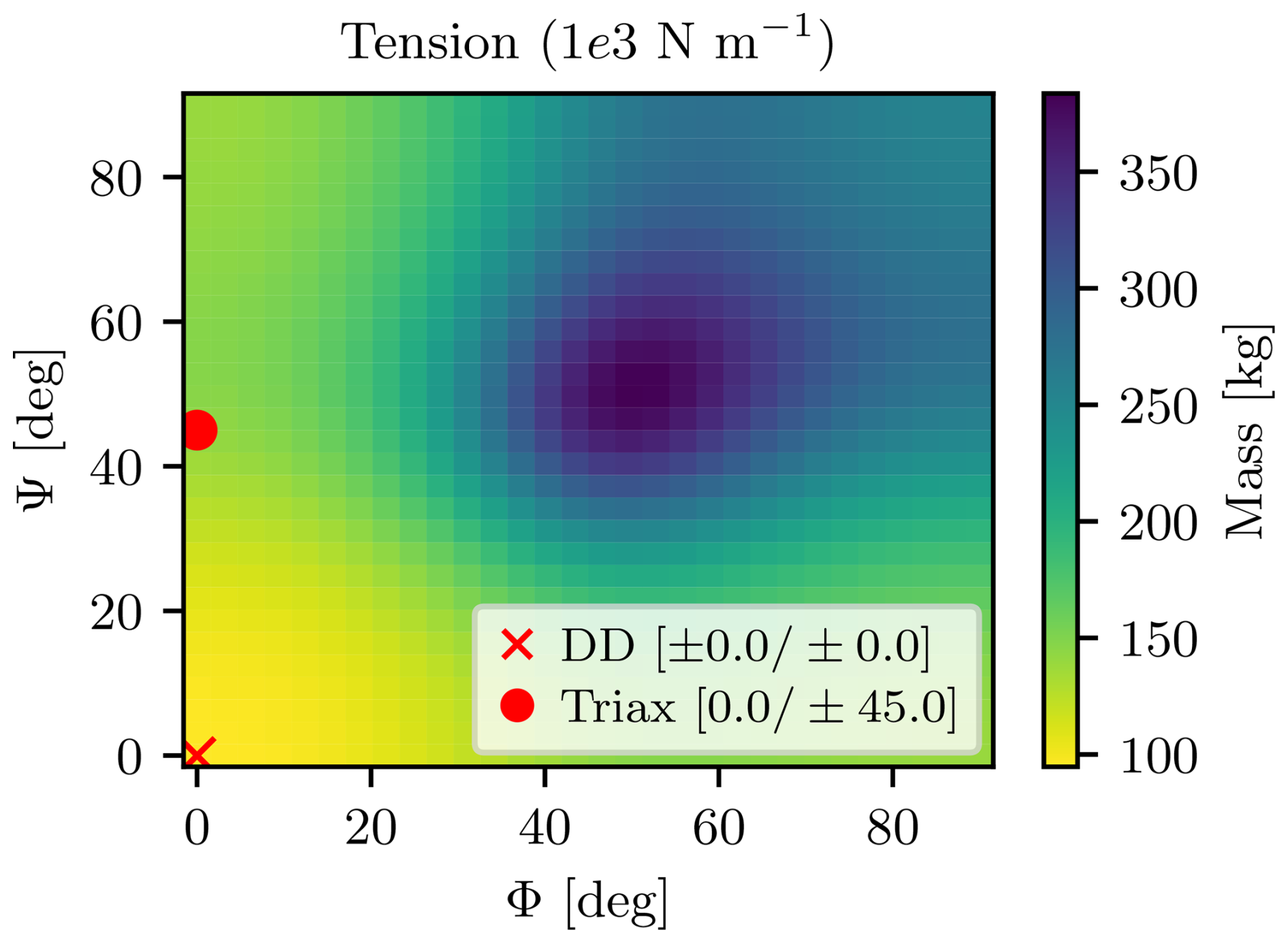
Under axial tension and compression (cases 1 and 2), the optimized DD laminate aligns both fiber angles with the load direction, defined here as Φ = Ψ = 0°, since the fibers act as the primary load carriers. Figure 4 illustrates the resulting mass distribution across different angle combinations: while the DD laminate converges to the optimal alignment, the triaxial configuration remains fixed, with one angle aligned with the load and the other offset by 45°, resulting in a mass increase. The compressive case exhibits nearly identical behavior, differing only in terms of allowable limits due to the material's higher tensile strength.
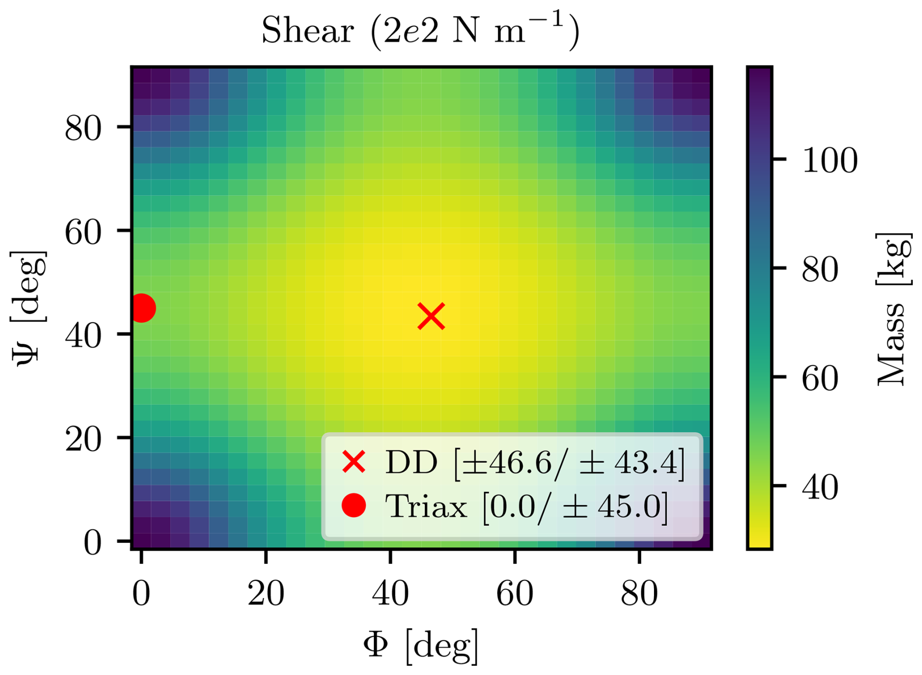
When subjected to pure shear (case 3), the optimal stacking shifts towards intermediate angles, with 45° emerging as the dominant orientation, as shown in Fig. 5. This response reflects classical shear mechanics, where maximum shear stress (τ12) is resolved along θ = 45° planes, producing a corner-driven deformation mode that is best resisted by fibers oriented in those directions. Once more, the Triax shows mass increase due to additional non-optimized 0° plies.
In the tension–shear case (case 4), shown in Fig. 6, the optimal fiber angles shift towards lower values, corresponding to the hard-laminate region. The solution remains offset from the (0,0) coordinate, with both Φ and Ψ lying between 0 and 45°. This trend is consistent with the pure tension and pure shear responses previously observed in Figs. 4 and 5.
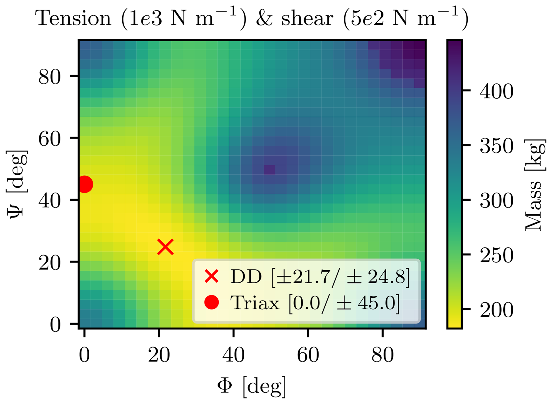
Figure 6Optimized mass distribution for the DD laminate under combined tension and shear loading.
Conversely, the compression–shear interaction (case 5), illustrated in Fig. 7, produces a markedly different result. The optimized angles shift towards higher values, which increases the off-axis orientation and, as a consequence, generates larger transverse normal stress σ2.
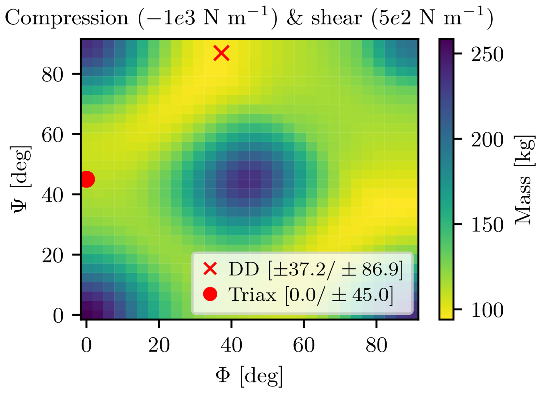
Figure 7Optimized mass distribution for the DD laminate under combined compression and shear loading.
This behavior follows directly from the Tsai–Wu interaction terms, shown in Fig. 8: the shear strength is coupled with the transverse normal stress, such that moderate compression in the transverse direction increases the effective shear strength. Physically, this corresponds to the fibers being laterally constrained by the matrix, which delays shear-driven failure. However, once σ2 becomes sufficiently large, the quadratic compression term dominates, and the allowable shear strength drops again. This mechanism explains why the proportion is critical for determining the optimal angle shift in this case.
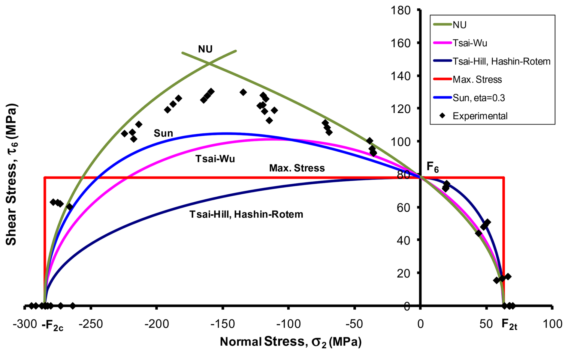
Figure 8Tsai-Wu τ12–σ2 failure envelope. Source: Daniel et al. (2011).
These results underscore that stiffness-based tailoring, even in its simplified form, captures design freedoms that are unexplored by triaxial laminates, whose fixed fiber arrangement constrains their ability to adapt to varying loads.
Conventional structural models in structural optimization, such as those used in previous large-blade studies, describe each panel through a set of homogenized layers (e.g., Sjølund and Lund, 2018; Hayat et al., 2022; Scott et al., 2022; Werthen et al., 2023). While efficient, this approach simplifies the internal composition of sandwich structures into equivalent layers within a laminate, typically limited to three homogenized materials.
The multi-parametric formulation introduces a modular description of composite panels (Fig. 9). Each panel is decomposed into a stack of independently parameterized sub-composites, each retaining its own material model and design variables. This structure allows, for example, Double-Double laminates to coexist with unidirectional or foam components within the same stack. Design variables are defined at the composite level, enabling independent control of each sub-component's parameters, such as fiber angles and thickness, without constraining them to a single, homogenized behavior. Whereas conventional models assemble stiffness from individual laminate layers, the new approach computes and superimposes the stiffness of each composite sub-component, maintaining analytical consistency while expanding the design space available for optimization.
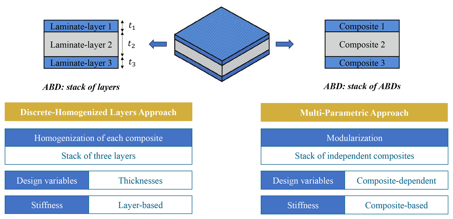
Figure 9Conceptual comparison between the discrete–homogenized and multi-parametric formulations.
3.1 Stiffness superposition
To enable a generalized treatment of stiffness for any combination of composite formulations, the stack must be interpreted as a sequence of materials, each characterized solely by its stiffness matrix, thickness, and position across the panel's thickness. This abstraction enables the creation of a global stiffness matrix [ABD]global from various combinations of materials, regardless of whether the underlying model is discrete or continuous. As long as each material supplies its individual stiffness matrix [ABD]local and total thickness, the modular integration remains intact.
The core principle enabling stiffness superposition is the analytical shift of the reference plane for each component, from its original mid-plane, as defined in classical laminate theory, to a common reference shared across all material blocks. This alignment allows for the consistent transformation of stiffness contributions, enabling their direct summation into a global stiffness matrix. The entire process is fully grounded in the CLT without introducing any additional assumptions.
Figure 10 illustrates the concept of an arbitrary reference plane shift for a single laminate.
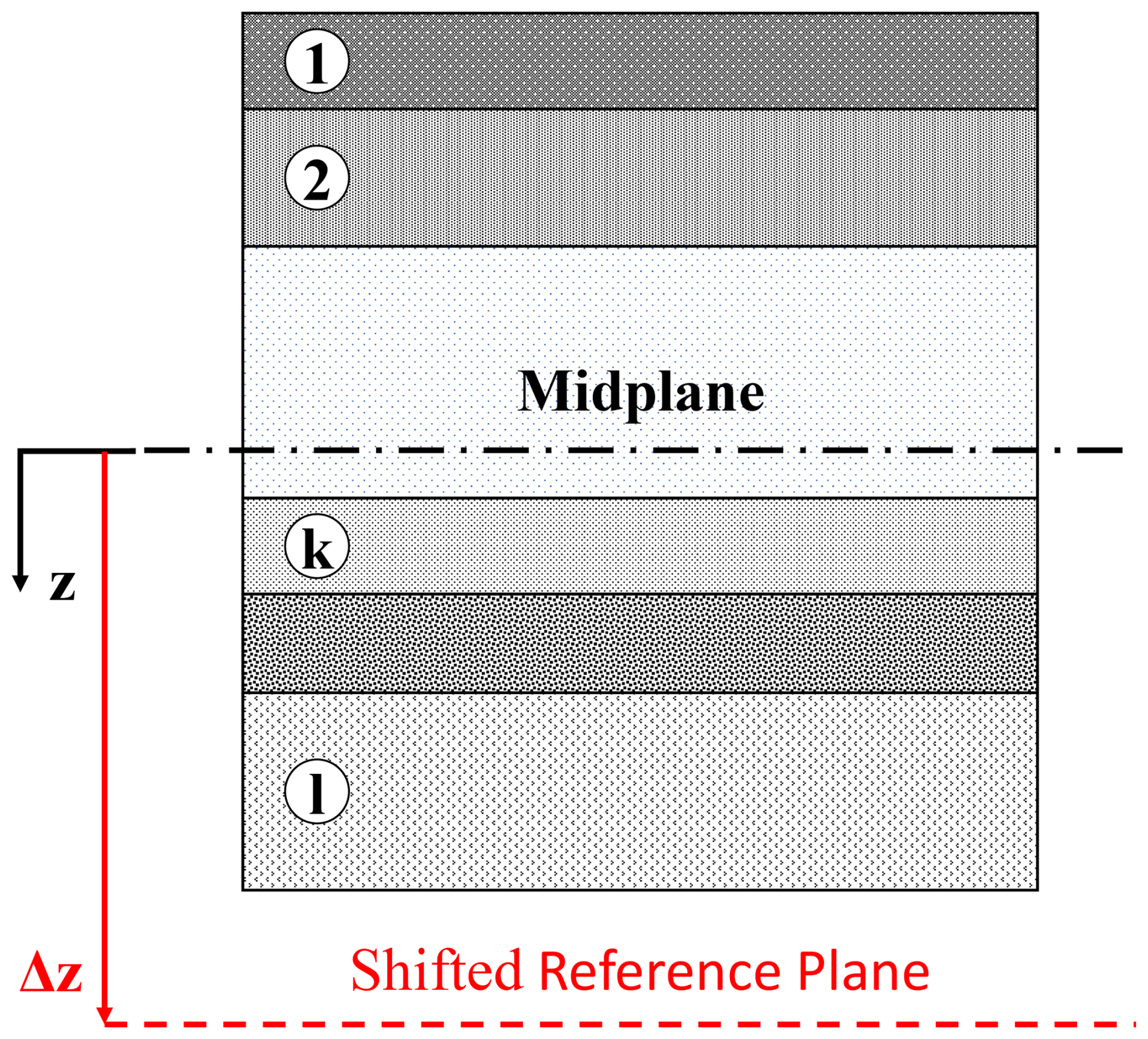
For such a shift, the position of any point along the thickness can be expressed as follows:
where z0 is the coordinate with respect to the original reference plane, Δz is the signed offset between the planes, and znew is the transformed coordinate relative to the new reference.
Using this definition, the transformed stiffness matrices [Anew], [Bnew], and [Dnew] can be defined as follows:
By substituting Fig. 11 into Eqs. (12), (13), and (14) and expanding each term, the transformed stiffness matrices can be written as functions of the original matrices (0) and the shift Δz. The resulting transformations are shown below, while their derivations are provided in Appendix A.
Once the [ABD] formulation is derived with respect to an arbitrary reference plane, the superposition of multiple composites can be consistently established. Figure 11 illustrates a generic stack composed of multiple material blocks, each contributing to the overall stiffness, given the plane shift to a common one.
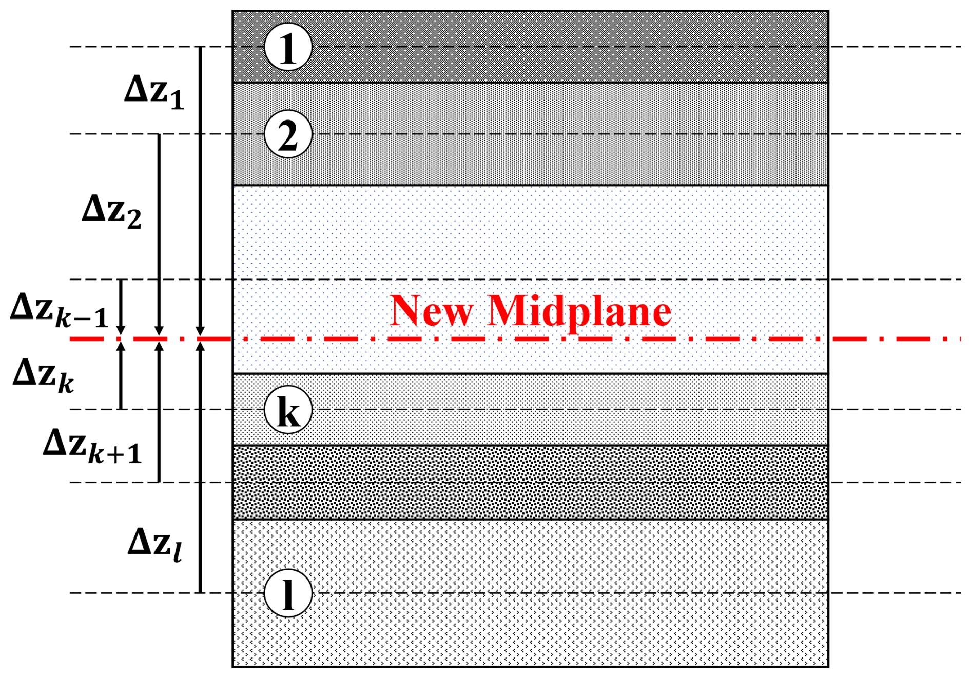
In general, the mold (and aerodynamic) surface should be used as the reference plane along the z axis to avoid overestimation of the bending stiffness. In the present study, the reference is set to coincide with the mid-plane of the whole stack, consistently with the plate formulation in which loads and deformations are defined relative to the mid-plane. The resulting superposition is given in Eqs. (16), (17), and (18).
3.2 Load distribution
In the context of structural assessment, stability and strength evaluations operate at distinct hierarchical levels. Stability is assessed at the panel level based on the global geometry, stiffness matrix, and applied loads. Once the governing criterion is defined, the procedure follows a fixed analytical pipeline dependent solely on these macroscopic parameters. Strength evaluation, in contrast, is performed at the material level to capture the behavior of each constituent composite. This requires distributing the global load state across the components of the stack so that each sub-composite is assessed independently based on its local strain field and failure criterion.
From the solver, each panel receives a set of membrane forces and bending moments, which serve as input loads for subsequent evaluations. For strength assessment, these loads are converted into strain quantities through inversion of the [ABD] matrix, following the plate stiffness relation described in Verein Deutscher Ingenieure (VDI) (2014).
The blade analyzed in this study is based on the structural layout of the IEA-15-240 reference wind turbine. This reference configuration features a blade span of approximately 117 m and a total mass of 65 t. Structurally, the blade comprises two main spars, along with leading-edge (LE) and trailing-edge (TE) reinforcements, all extending from 10 % to 95 % of the span.
Internally, the structure combines triaxial glass fiber laminates in the outer shell with core materials that vary along span and circumference. UD carbon laminates are used in the spar caps to provide high bending stiffness with minimal added mass, while UD glass layers reinforce the leading and trailing edges under edgewise loading. Foam cores occupy the space between spar caps and edge reinforcements beyond the root, improving buckling resistance and bending stiffness. The shear webs are also built as sandwich panels, using biaxial glass face sheets bonded to foam. Figure 12 illustrates this composition at four representative cross-sections along the blade span.
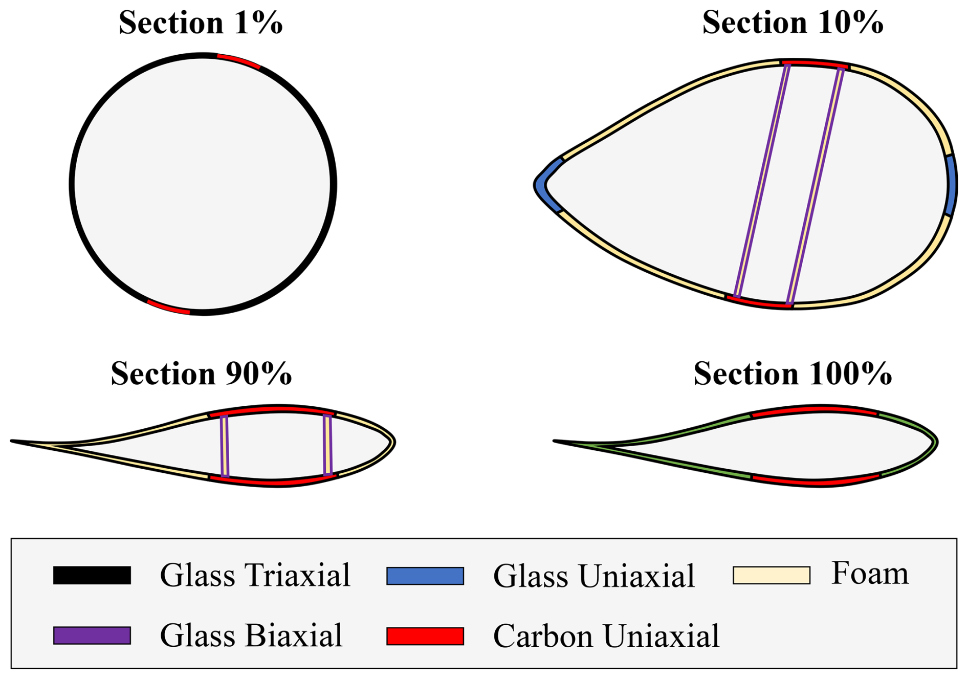
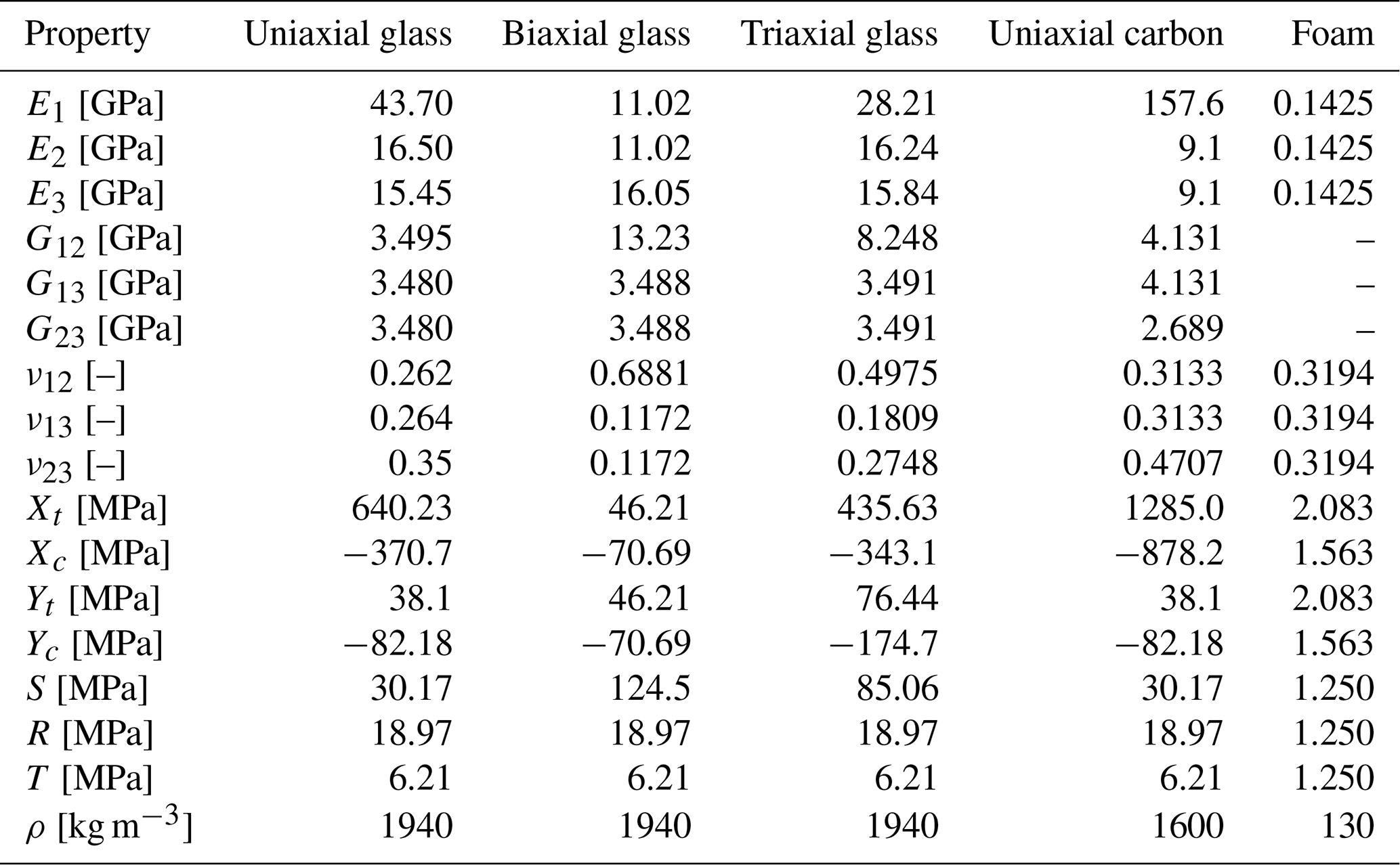
The IEA-15-240 material dataset provides a solid reference basis but contains a few undefined parameters, including Poisson's ratios for biaxial and triaxial glass laminates, as well as some missing properties for the unidirectional carbon material. To enable a comprehensive structural assessment, the CRC-15-240 blade utilizes the material definitions from the IEA-22-240 reference wind turbine (Zahle et al., 2024), which provides an updated dataset developed by Camarena et al. (2022). For all laminates, the material coordinate system is defined such that the E1 direction is oriented spanwise, tangentially to the shell reference surface. The values used in this study are summarized in Table 2.
Table 2Mechanical properties of composite and isotropic materials used in the CRC-15-240 blade. Composite values from Camarena et al. (2022).
Moreover, panel-level analyses of the baseline model reveal localized instability near the blade tip, where spar caps taper and the leading- and trailing-edge reinforcements are discontinued, as reported by Scott et al. (2022). To mitigate this effect and increase bending stiffness in these regions, the CRC-15-240 model introduces foam cores where the reinforcements are absent, thereby maintaining a continuous sandwich configuration along the blade span.
The following sections describe the complete simulation and optimization framework employed for the CRC-15-240 blade. “Simulation setup” details the aeroelastic analyses, load processing procedures, and the solver–optimizer integration environment. “Structural model initialization” introduces the spanwise and circumferential discretization of the blade. “Loading and boundary conditions” summarizes the design load cases and the procedure for extracting the load envelopes. “Coupling and constraints” specifies the structural requirements imposed during the optimization process. Finally, “Parametrization and optimization setup” presents the parametrization strategies adopted in the analysis and provides an overview of the optimization workflow.
4.1 Simulation setup
The simulation and optimization of the CRC-15-240 blade are conducted using a modular pipeline that integrates aeroelastic simulation, load processing, structural modeling, and gradient-based optimization. The overall workflow is shown in Fig. 13, illustrating the data exchange between the main tools involved.
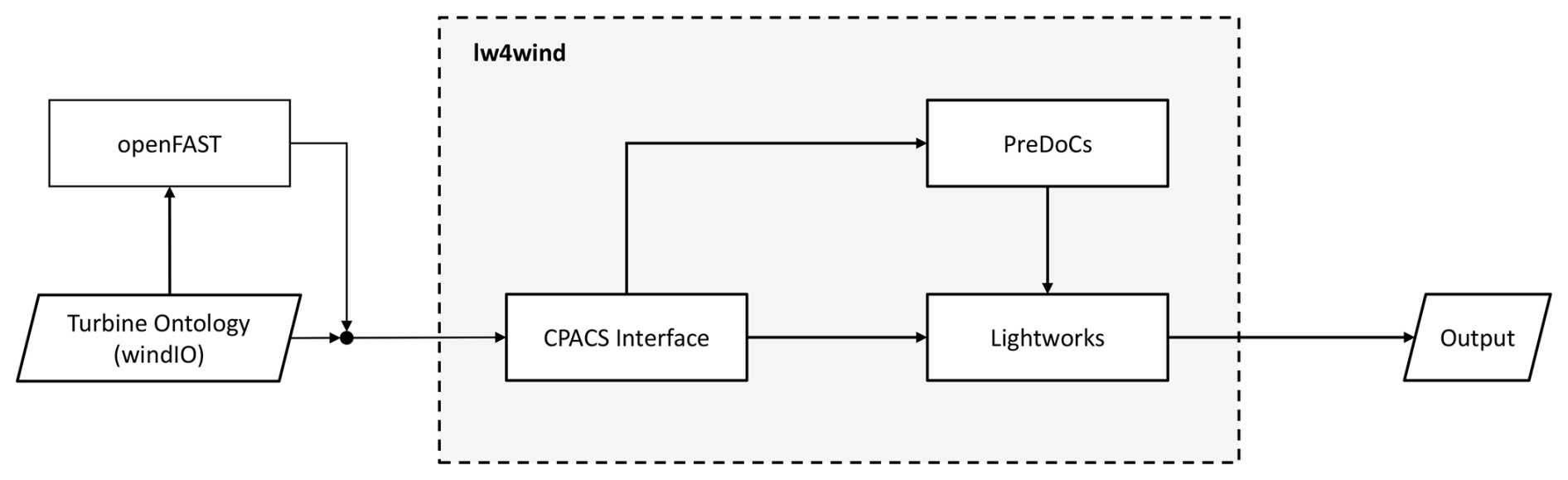
At the core of this process lies the lw4wind1 environment, which manages communication between all modules. The simulation begins with an aeroelastic analysis in OpenFAST, generating time series of aerodynamic and inertial loads along the blade span. These results are then embedded into a WindIO file (Bortolotti et al., 2022), an ontology scheme that defines the storage of wind turbine engineering parameters in a hierarchical yaml structure.
After load embedding, the pipeline proceeds to the structural modeling stage. The WindIO file is parsed through the CPACS interface, which performs the format conversion and initializes the structural solver PreDoCS (Preliminary Design of Composite Structures, Werthen et al., 2024). This stage defines the spanwise structural representation of the blade and sets up the optimization problem.
PreDoCS performs the structural analysis of the blade as a continuous anisotropic beam governed by Timoshenko theory. During initialization, the blade span is discretized into cross-sectional stations, for which section properties and fully coupled 7 × 7 stiffness matrices are assembled. The solver computes the spanwise displacement field under applied external loads, from which internal loads are recovered using the cross-sectional stiffness relations described by Jung and Nagaraj (2002).
Once initialized, lightworks takes over the local structural representation, mapping each beam section to a detailed set of composite panel models. During optimization, PreDoCS and lightworks operate in parallel: PreDoCS provides the individual panel load states, while lightworks evaluates local stiffness, strength, and stability responses. Following convergence, the optimization results are post-processed.
4.2 Structural model initialization
After conversion of the blade geometry into the CPACS format, the model is segmented into structural panels. Circumferentially, each cross-section is divided into regions following WindIO conventions, which define the structural layout illustrated in Fig. 12 for different span positions.
In the spanwise direction, the blade is discretized using a two-zone uniform scheme. From the root (0 %–23 % span), panels are spaced at 2.60 m to capture the highly loaded root region and the transition from the cylindrical base to the main blade with spars. Beyond 23 % span, a coarser spacing of 4.50 m is applied up to the tip, reducing computational cost while maintaining geometric continuity and manufacturability, given that taper plays an important role in composite-panel design. The model comprises 30 cross-sections in total. Since internal loads are evaluated analytically, a finer discretization is not required. A maximum envelope criterion is applied for load selection, ensuring conservative results.
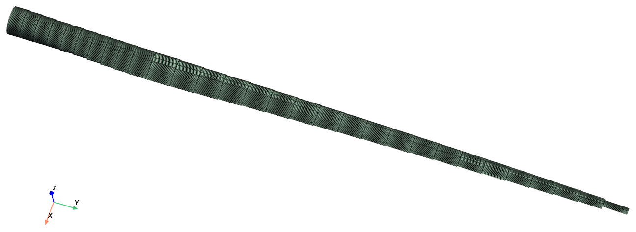
In addition to spatial control, the sections are aligned with the blade's actual load axis, which follows the curved blade geometry. The resulting model is visualized in Fig. 14.
4.3 Loading and boundary conditions
The loads used in this analysis represent the transient response of the nominal IEA-15-240 reference model. Aero-servo-elastic simulations are performed in OpenFAST using the ElastoDyn module, which applies an Euler–Bernoulli beam formulation with two bending modes: flapwise and edgewise deflections (Rinker et al., 2020). Building upon the structural analysis of the scaled 22 MW blade presented by Werthen et al. (2023), a reduced subset of design load cases is defined in accordance with the guidelines of DNVGL-ST-0376 (DNV GL, 2015). The selected load cases are summarized in Table 3.
Table 3Design load cases and corresponding wind speeds used in the simulation.

For each load case, time series of aerodynamic and inertial loads are post-processed to extract the critical design conditions. Following the DNVGL-ST-0376 guideline (DNV GL, 2015), envelopes of all force and moment components are generated by evaluating their minimum and maximum values, including additional bending moments computed in the flap–edgewise plane at 30° intervals from 0 to 180°. The corresponding time steps associated with the maximum flapwise and edgewise tip deflections are also included.
4.4 Coupling and constraints
The model is subject to five categories of constraints: coupling, strength, stability, taper, and deflection. A safety factor of 1.5 is applied to all evaluated constraints, whereas coupling relations are enforced directly and therefore excluded from this factor, following the definitions adopted by Werthen et al. (2023).
-
Coupling relations are applied to ensure consistent material behavior across the blade. Intra-panel coupling enforces symmetry through the sandwich thickness, mirroring the outer composite about the mid-plane while maintaining the uniqueness of the core. Inter-panel coupling links corresponding composites between the upper and lower shells, ensuring material symmetry despite their geometric differences. These relations remain fixed throughout the optimization.
-
Strength constraints are applied at the composite level and depend on the specific class of each material. For those modeled as single-ply laminates, the Tsai-Wu criterion (Amabili, 2018) is employed, widely used in structural analysis and optimization studies due to its computational efficiency and limited material parameter requirements. For DD laminates, the Omni-Envelope criterion is adopted, as detailed in Sect. 2.3. Finally, the foam cores, due to their isotropic behavior, are evaluated using the von Mises criterion.
-
Fatigue constraints are applied to the laminates as a simplified maximum strain criterion, based on strain limits considered to be sufficiently conservative for use without material testing (DNV GL, 2015):
where γm is the material safety factor, and Rd is the design value of the material property. These limits are verified for all four ply orientations of the DD laminate at each optimization step.
-
Stability constraints are evaluated at the panel level to account for local buckling under axial compression and in-plane shear. Assuming an orthotropic and symmetric laminate, the critical buckling load per unit width under compression is given by Industrie Ausschuss Struktur Berechnungsunterlagen (IASB) (2009) (HSB-45112-02) as
and that for shear-dominated buckling is given by Industrie Ausschuss Struktur Berechnungsunterlagen (IASB) (2009) (HSB-45111-08) as
Here, and denote the laminate’s effective bending-stiffness terms, while kx and ks are the buckling coefficients for compression and shear, respectively. These coefficients are interpolated from the provided curves, assuming simply supported boundary conditions for all panel edges to yield conservative estimates.
To account for through-thickness shear effects in the buckling analysis of sandwich panels, both critical buckling loads (compression and shear) are modified following Kassapoglou (2013):
where tc and Gc denote the core thickness and transverse shear modulus, respectively, and k is the shear correction factor, set to k ≈ 1. This choice is conservative for sandwich panels, where the core shear stiffness is low relative to that of the face sheets (Kassapoglou, 2013).
Since both axial and shear loads act simultaneously, the overall stability assessment combines the two modes through the interaction criterion proposed by Peters (1954):
where R denotes the ratio between the applied and critical load for each mode.
-
Tapering constraints prevent abrupt thickness variations between adjacent panels. All materials satisfy the DNVGL-ST-0376 requirements (DNV GL, 2015), except for the shell face sheets, which show a localized acute thickness drop near the root–mid-span transition where spars and reinforcements are introduced. Following Tsai (2021), a specific constraint is applied to the DD laminates, allowing taper ratios up to 7.5 : 1.
-
Deflection constraints are added to all use cases to limit the maximum allowable blade tip displacement under extreme load cases. These constraints ensure the tower clearance of the blades.
4.5 Parametrization and optimization setup
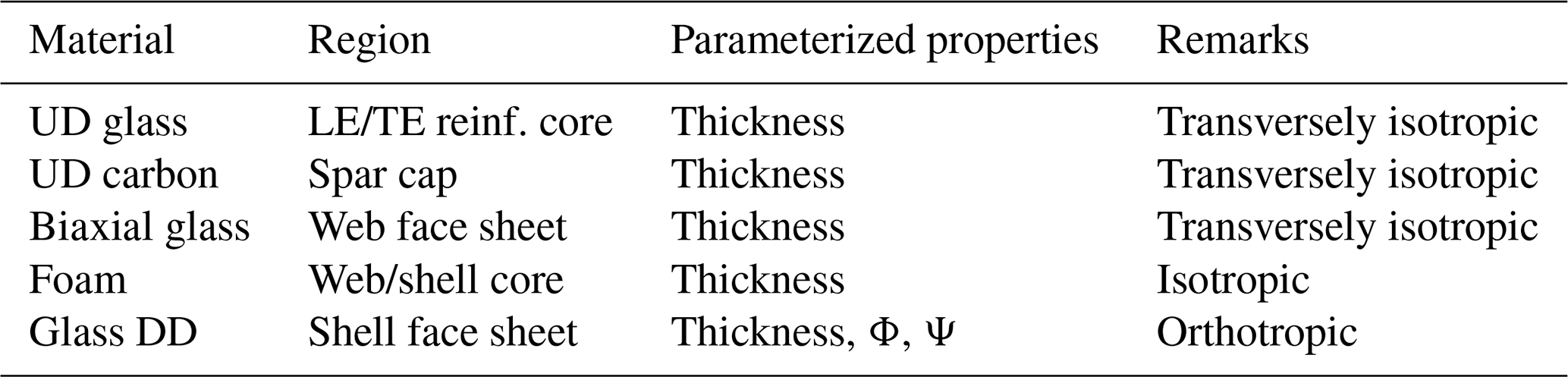
Each panel in the blade is initialized with a multi-parametric scheme that enables multi-layer sandwich configurations composed of distinct sub-components, allowing each layer to be parameterized independently. Glass unidirectional, biaxial, and unidirectional carbon laminates are modeled as transversely isotropic single plies, while the foam core is treated as isotropic. These composites are optimized solely by their thicknesses across different panels.
The main innovation is the substitution of the triaxial glass laminates with Double-Double laminates, moving from a homogenized stacking to a configuration composed of unidirectional glass plies, which can be tailored in terms of thickness and stiffness through the ply angles (Φ,Ψ). To ensure consistent comparison, the baseline case also employs the DD formulation with fixed angles , equivalent to the nominal triaxial stacking and part of the DD design space (Fig. 3). This substitution removes inconsistencies in material properties and strength criteria, allowing all configurations to be assessed within a unified modeling approach.
Building upon this baseline, a series of simulation cases is defined with increasing levels of design freedom regarding the DD skin parametrization. The different optimization scenarios are shown in Table 4.
Table 4Comparison of DD laminate configurations and variable definitions.
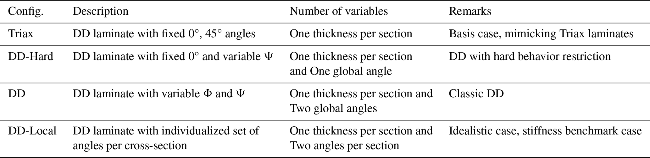
In all cases except DD-Local, the fiber angles are uniform across all panels, meaning each panel adopts the same globally optimized orientation. Only the laminate thicknesses vary along the blade span. The locally optimized case is introduced to explore the potential of angle tailoring per cross-section along the blade in response to localized structural demands. While not directly manufacturable, this configuration provides insights into the maximum achievable performance through local stiffness adaptation.
An overview of the materials employed in the CRC-15-240 blade and their corresponding parametrization strategies is presented in Table 5.
Table 5Material models and parametrization strategies in the CRC-15-240 optimization.
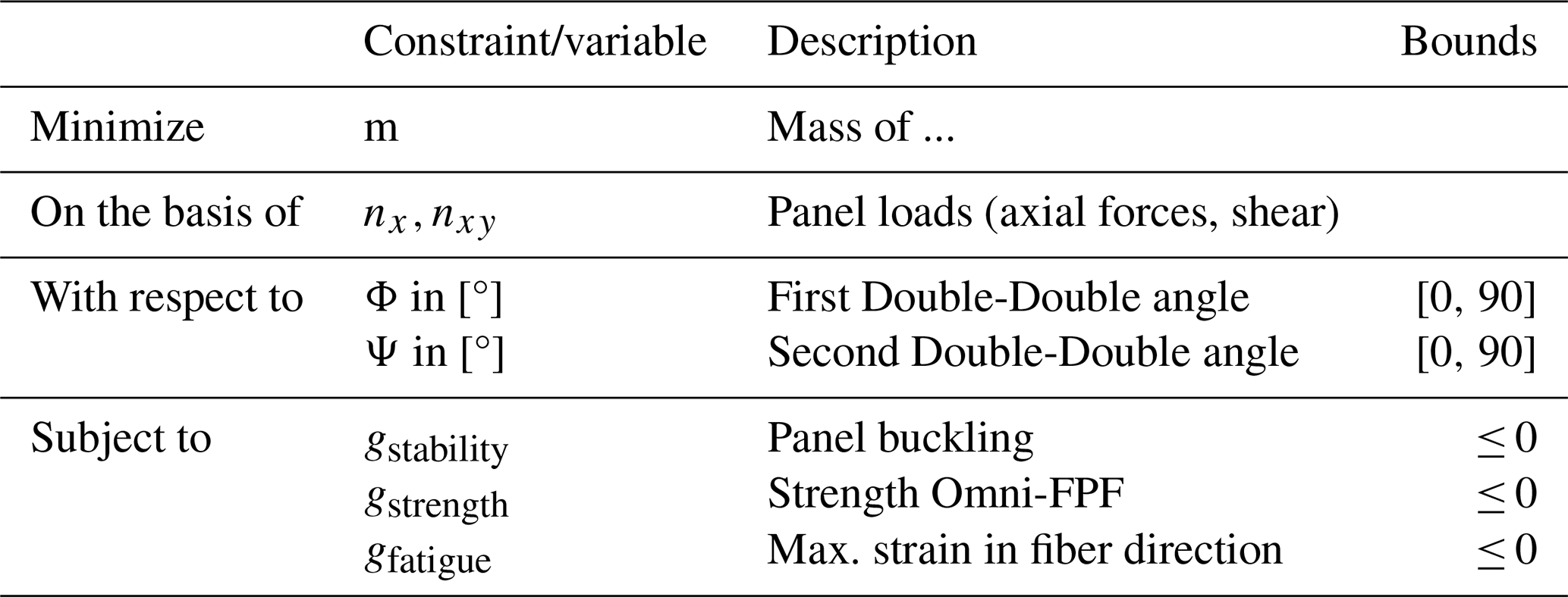
The optimization aims to minimize the total structural mass of the blade, subject to strength, simplified fatigue, stability, taper, deflection, and coupling constraints. The problem is solved using the Sparse Nonlinear OPTimizer (SNOPT), a gradient-based sequential quadratic programming algorithm that solves large-scale constrained problems through iterative quadratic approximations. Preliminary tests showed that SNOPT achieved more robust convergence than the Interior Point Optimizer (IPOPT) and the Method of Moving Asymptotes (MMA). The solver parameters follow standard definitions, except for the feasibility and optimality tolerances, which are set to 10−4. For the usage of gradients, a check of the robustness of the results against varying initialization and perturbations has to be performed. Optimizations are started from different DD angle combinations like those described in Zerbst et al. (2025). The mass optimum could be achieved with a reliability of over 90 %. The overall optimization framework is summarized in Table 6.
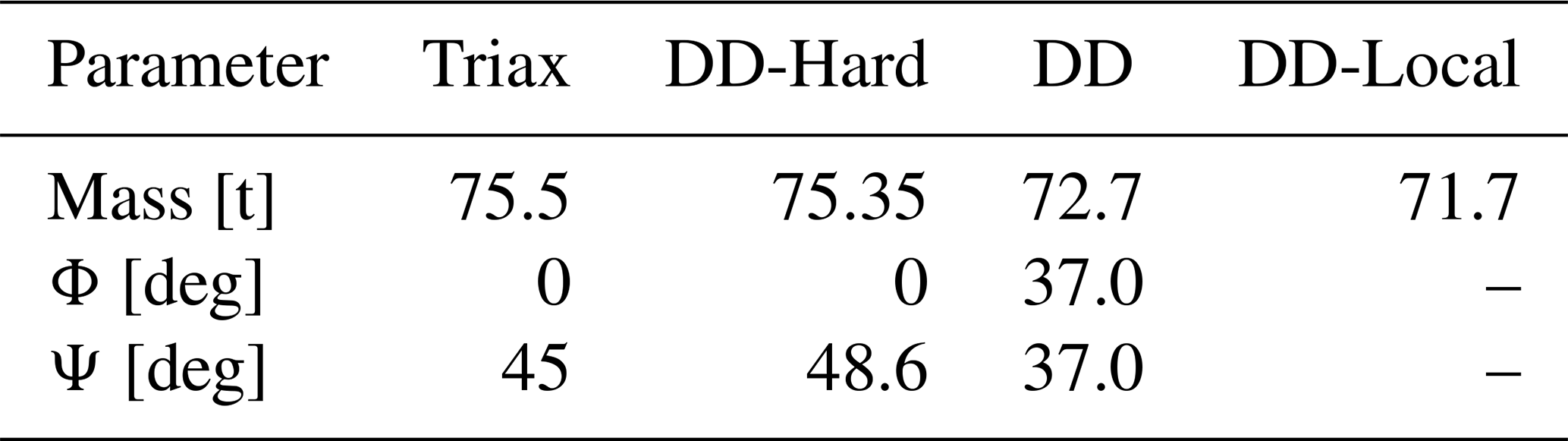
The optimization outcomes for all design cases are summarized in Table 7. The triaxial and DD-Hard configurations yield nearly identical masses, which indicates that the 0° plies dominate the overall stiffness, while the second angle exerts only a minor influence. In contrast, introducing full angular freedom in the DD case results in a mass reduction of 4 % (2800 kg) relative to the triaxial baseline, highlighting the relevance of full directional control of the fiber orientations. The DD-Local case, which permits section-wise variation of Φ and Ψ, achieves an additional improvement of 1.38 % (1000 kg) compared to the DD case.
Table 7Comparison of mass and optimized angles for each design case.
The optimized fiber orientations show a general shift towards softer laminates in the direction of ±45°, reflecting a compromise between spanwise stiffness and buckling resistance. This trend is illustrated in Fig. 15, which maps each configuration onto the lamination parameter design space.
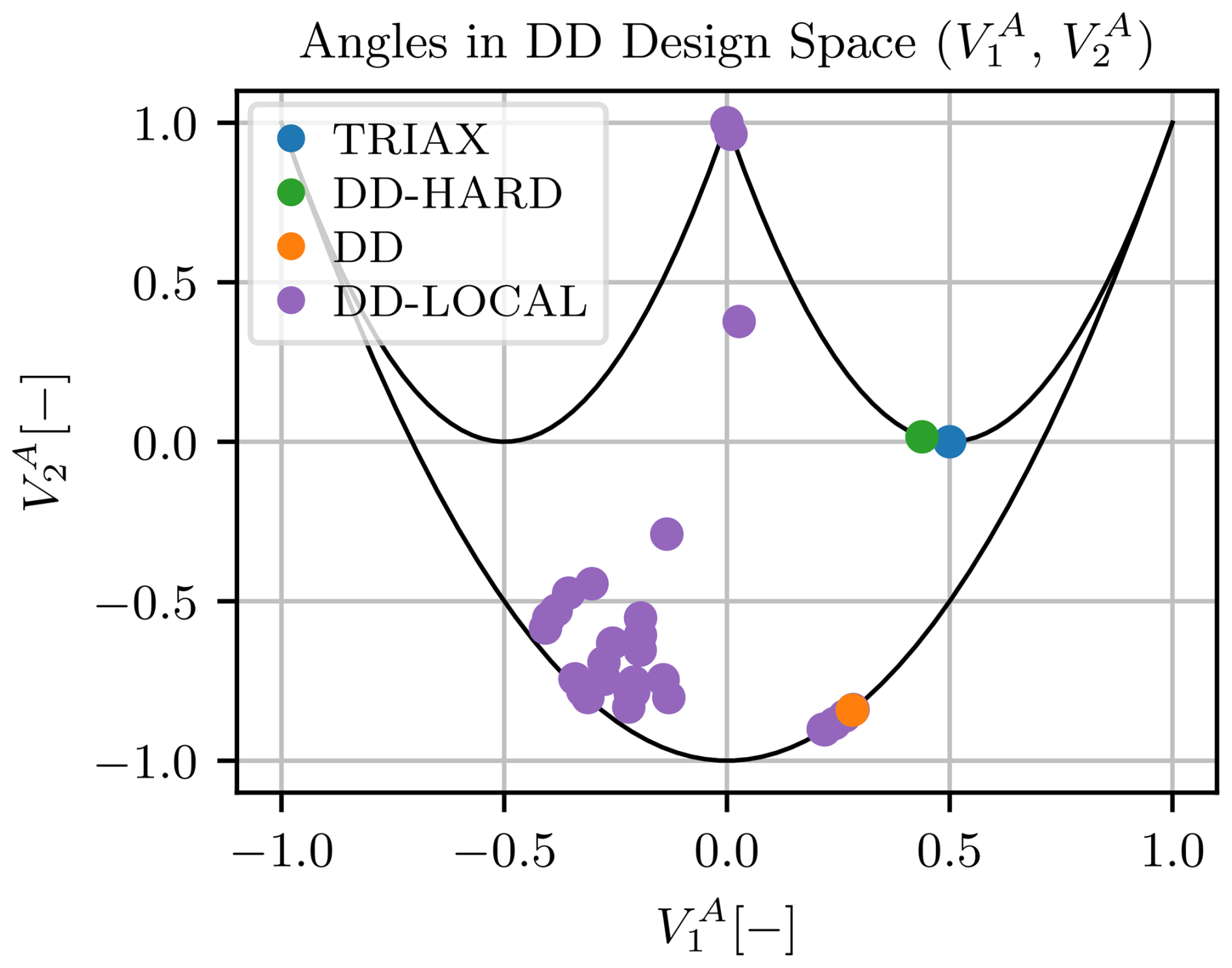
The Triax configuration remains fixed, while the DD-Hard model increases the second angle slightly to reduce axial stiffness along the span. Despite this adjustment, both configurations exhibit similar stiffness behavior, positioned within the “hard” region identified by Tsai (2021). This explains the marginal difference in their optimized masses as the limited variation of approximately 3.5° in the second angle produces only minimal changes in stiffness.
In contrast, the DD case, where both angles are freely optimized, is driven towards the softer region of the lamination parameter space, near the ±45° boundary of the feasible domain. This reflects a structural preference for combining spanwise stiffness with shear and buckling resistance, with Φ and Ψ converging to approximately 37°. The DD-Local case follows a similar trend for most panels, though softer angles are adopted in the trailing-edge panels of the rear shell to prevent local buckling, and 90° orientations appear near the maximum chord region (at 27 m), contributing edgewise bending stiffness in this region.
The spanwise mass distribution for all configurations is presented in Fig. 16. The influence of laminate stiffness tailoring is evident: shell stiffness directly governs the structural mass profile. The Triax and DD-Hard cases exhibit nearly identical distributions.
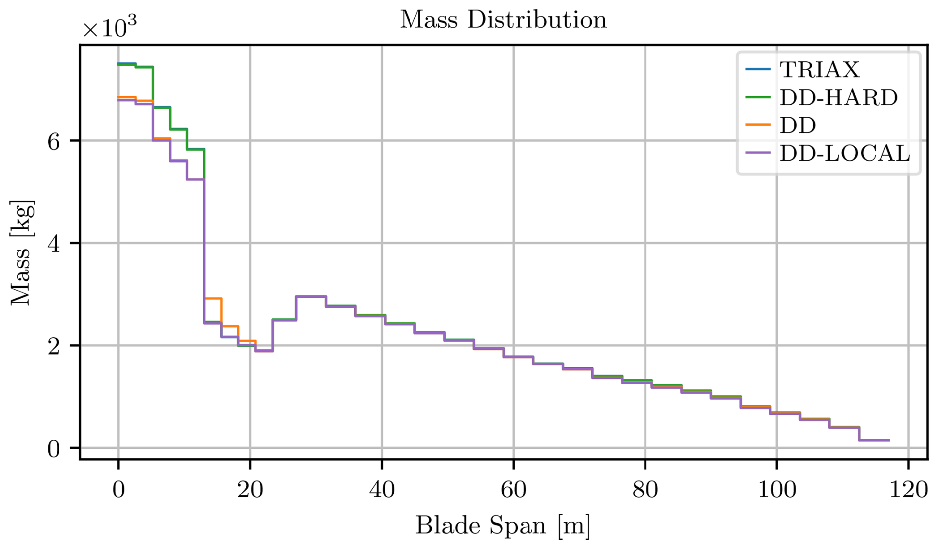
Nevertheless, the total mass difference between the Triax and DD cases amounts to 2800 kg. The root region, marked by a significant mass drop, accounts for approximately 70 % of the total reduction (1960 kg), while the remaining 30 % (840 kg) is distributed along the mid-span and tip. This concentration of mass reduction near the root highlights its dominant role in the optimization, driven by the region's structural simplicity and exposure to high loads. It consists solely of two spar-cap cores and two face-sheet layers, making it highly sensitive to stiffness adjustments.
Between the DD and DD-Local models, a distinct trend emerges: the DD-Local configuration achieves a lower mass between the root and max chord. This behavior reflects the additional flexibility of the DD-Local setup, which allows localized stiffness adaptation.
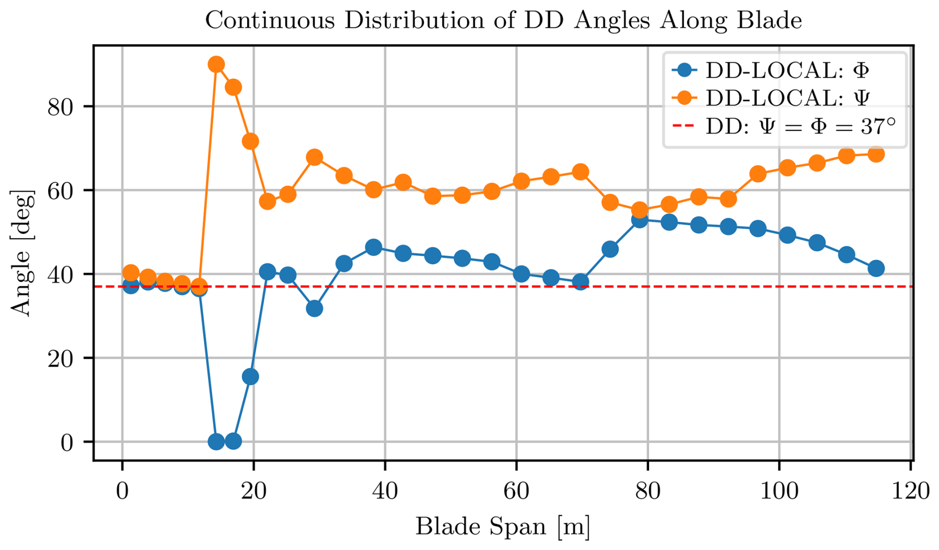
This is further evidenced by Fig. 17: in the cylindrical root region, the DD-Local angles cluster around 37°, coinciding with the globally optimized DD solution. Since this region contributes the largest share of mass savings, it dominates the global optimum for the DD case – when a single angle pair is enforced across the entire blade, the optimizer converges to the value that minimizes mass in the most weight-critical zone. Beyond the root, where spars and reinforcements assume the primary load-bearing role, the DD-Local case adapts its angles to local structural demands and diverges from the one-angle solution.
Figure 17 shows that, in the cylindrical root region, the DD-Local angles cluster around 37°, coinciding with the globally optimized DD solution. Since this region contributes the largest share of mass savings, it explains the global optimum for the DD case: a single angle pair enforced across the entire blade naturally converges to the value that is most beneficial in the most weight-critical zone. Beyond the root, where spars and reinforcements assume the primary load-bearing role, the DD-Local case adapts its angles to local structural demands, and the two solutions diverge. Nevertheless, 37° remains the most effective uniform configuration overall.
Given that the DD-Hard configuration shows limited gains relative to the triaxial baseline, it confirms that restricting Φ = 0° leaves little room for stiffness tailoring. As DD-Hard and DD-Local serve as boundary references – the former being a near-triaxial constraint and the latter being an idealized stiffness benchmark – the following analysis focuses on the Triax and DD cases as the most meaningful comparison.
5.1 Comparative analysis of triaxial and DD configurations
The thickness profiles provide a direct physical interpretation of how laminate architecture influences mass distribution. Figure 18 compares the spar-cap and shell-skin thicknesses for the Triax and DD configurations. Near the root, within the cylindrical section, the lay-up exhibits a 7 % greater shell-skin thickness than the configuration. Conversely, the DD lay-up requires a 2 %–6 % greater spar-cap thickness through the transition region towards maximum chord. This trade-off highlights how laminate orientation affects not only its own stiffness but also the material demand in adjacent structural components.
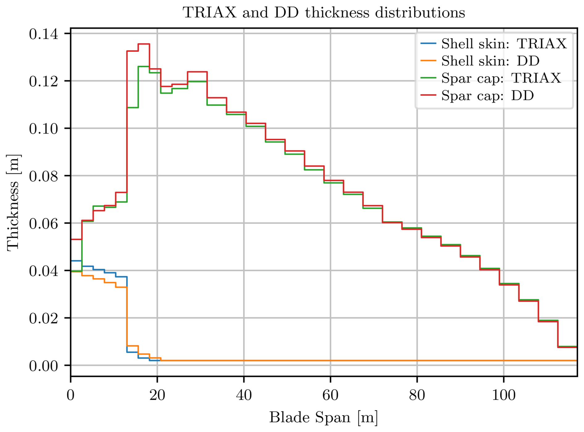
After the cylindrical sections, the shell-skin thickness shows a progressive loss in structural relevance as spars and edge reinforcements assume the primary load-bearing function. A marked reduction occurs at the sixth section (sixth step in Fig. 18), limited by the tapering ratio of 7.5. For the triaxial skin, the thickness decreases from 37.3 to 5.5 mm over the local span; for the DD configuration, it decreases from 32.7 to 8.2 mm, both matching the allowable slope. By the ninth section, both skins attain their minimum allowable thicknesses of 2.0 mm.
Given the root section's significant mass contribution and the strong influence of DD angles, this region is analyzed in more detail. The stiffer the laminate is in the direction of load application, the greater the expected concentration of membrane forces. This effect is evident in Fig. 19, where axial loads Nx concentrate within the spar-cap region due to the thick unidirectional CFRP layers.
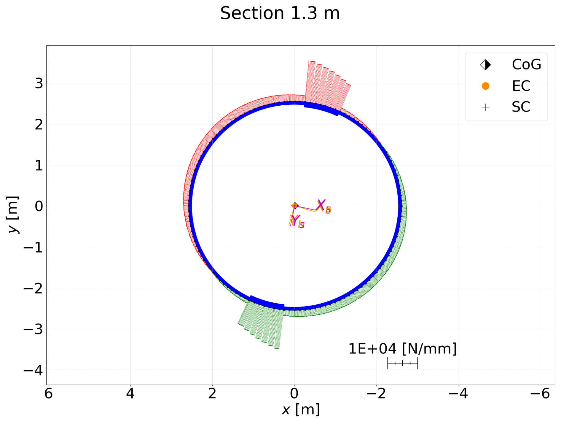
Figure 19Axial force distribution (Nx) for the critical minimum edgewise moment case (Triax and DD).
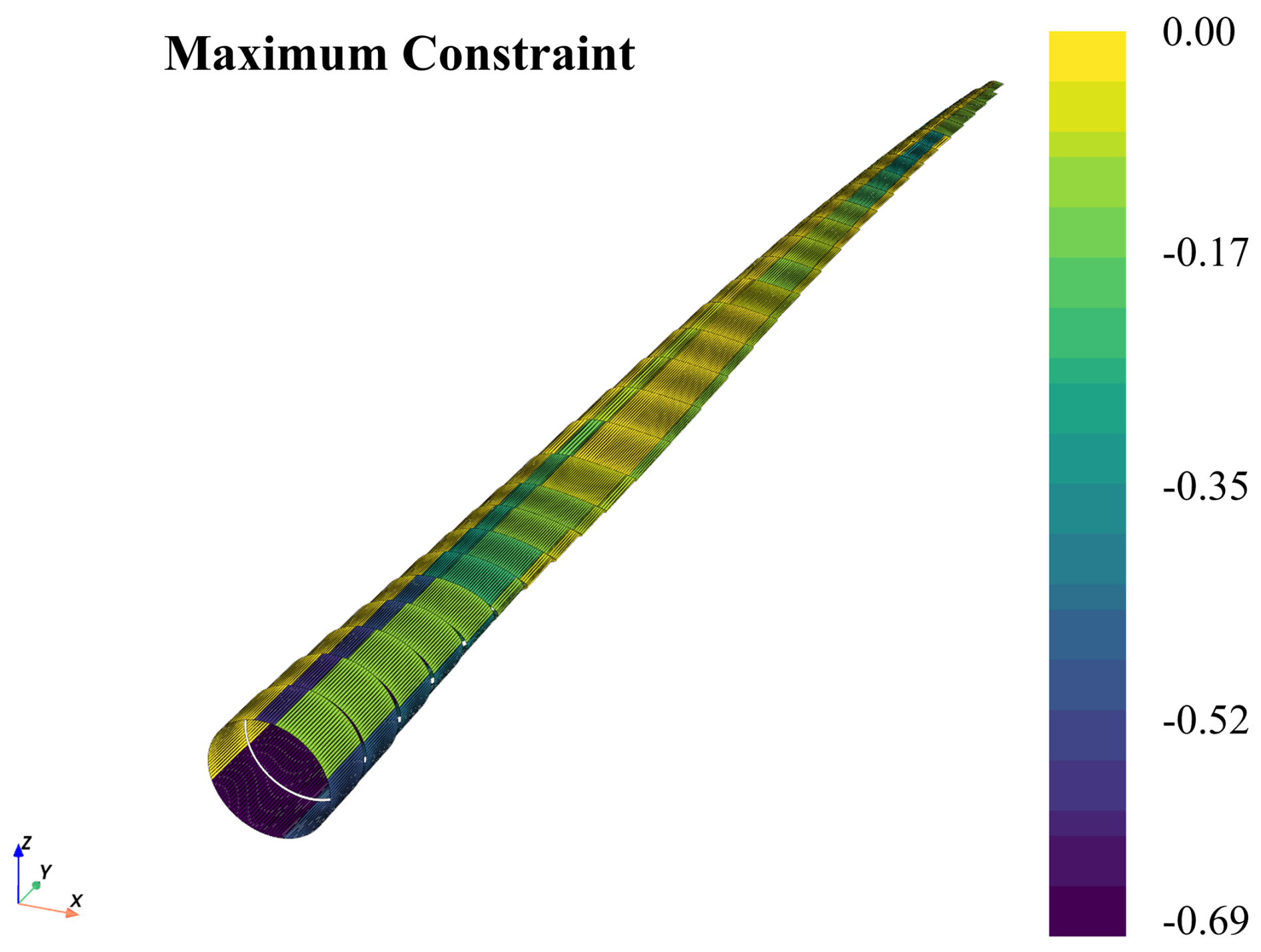
However, the triaxial laminates contain a larger portion of 0° plies, which concentrate excessive axial stiffness in the face sheets. Considering the superior strength-to-weight ratio of CFRP and the structural role of the spar cap, this behavior contradicts the most efficient stiffness distribution. As shown in Fig. 20, the spar cap remains far from the constraint threshold of 0, while the shell operates at its limits. Consequently, the optimizer first increases the spar-cap thickness to relieve part of the load carried by the shell, which acts as a sinking component. In addition, the 0°-dominated lay-up provides poor buckling resistance, further requiring local thickening of both the spar-cap and shell face sheets.
In terms of trailing- and leading-edge reinforcements, as shown in Fig. 21, they follow a similar overall trend for both the Triax and DD configurations. Reinforcements are generally thinner in the Triax case, primarily due to the additional axial stiffness provided by the 0° plies in the skin. In contrast, the DD configuration lacks this axial reinforcement from the skin, and the UD core must compensate for this, resulting in thicker reinforcements.
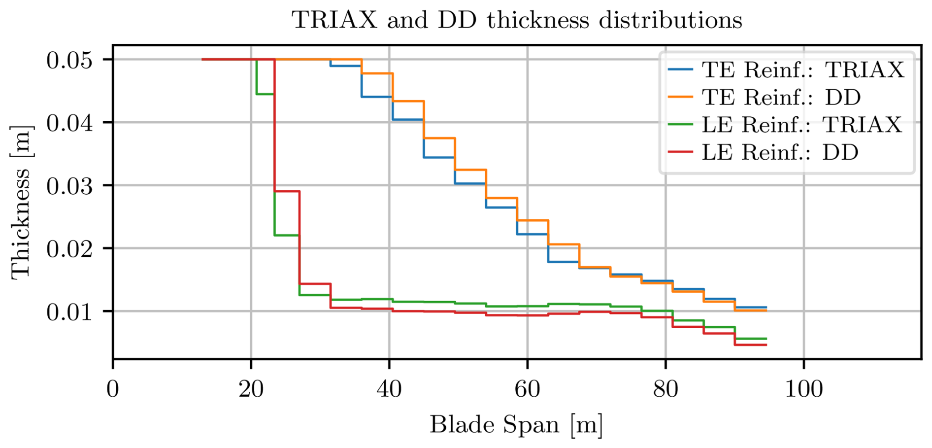
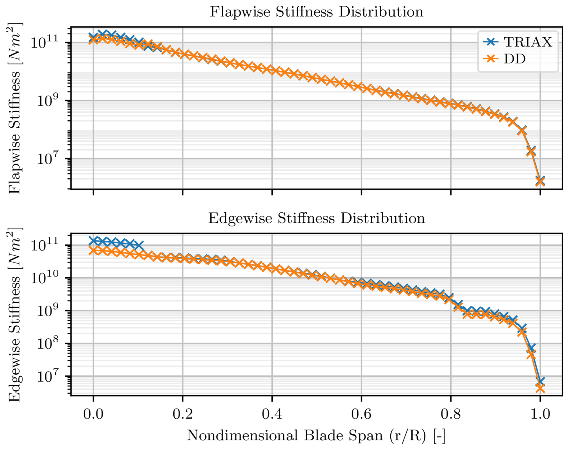
Figure 22Flapwise (upper) and edgewise (lower) stiffness distributions for both configurations.
Given the redistribution of loads between shell skins, spar-cap cores, and LE and TE reinforcements, spanwise variations in blade stiffness can occur. As shown in Fig. 22, some minor change in flapwise stiffness occurs near the root, where the DD is softer due to its reduced spar-cap thickness. Beyond this region, the spar-cap thicknesses in both configurations converge, leading to similar stiffness trends along the remaining span. In contrast, the edgewise stiffness distribution exhibits a larger root region offset, even though both configurations converge along the span. In edgewise bending, the spar cap contributes less to stiffness, shifting the dominant role to the reinforcements and shell skins. The Triax skin, with its higher axial stiffness, therefore provides greater support, particularly at the root and near the tip where LE and TE reinforcements terminate. In these regions, the skin dominates the edgewise response.
5.2 In-depth analysis of the optimized DD blade
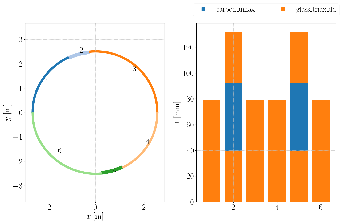
Near the root (Fig. 23), the configuration reveals a structurally simple yet heavily reinforced section. The high material density in this region reflects its critical role in load transfer, particularly through the spar cap and shell skin. The skin plays a dominant role in this area and benefits the most from optimization, as previously discussed.
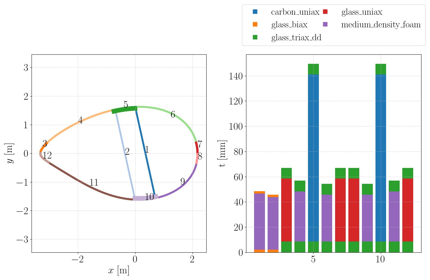
Progressing outward, Fig. 24 illustrates the transition in structural composition with the introduction of foam cores, UD glass reinforcements, and the shear webs. Among the lay-ups originating from the root, only the spar cap maintains the same thickness distribution trend. In contrast, the shell skin rapidly decreases in thickness and structural relevance, in line with the shift towards spar- and reinforcement-dominated load paths. The foam core has its highest thickness value at 19 % of the span shown in Fig. 25.
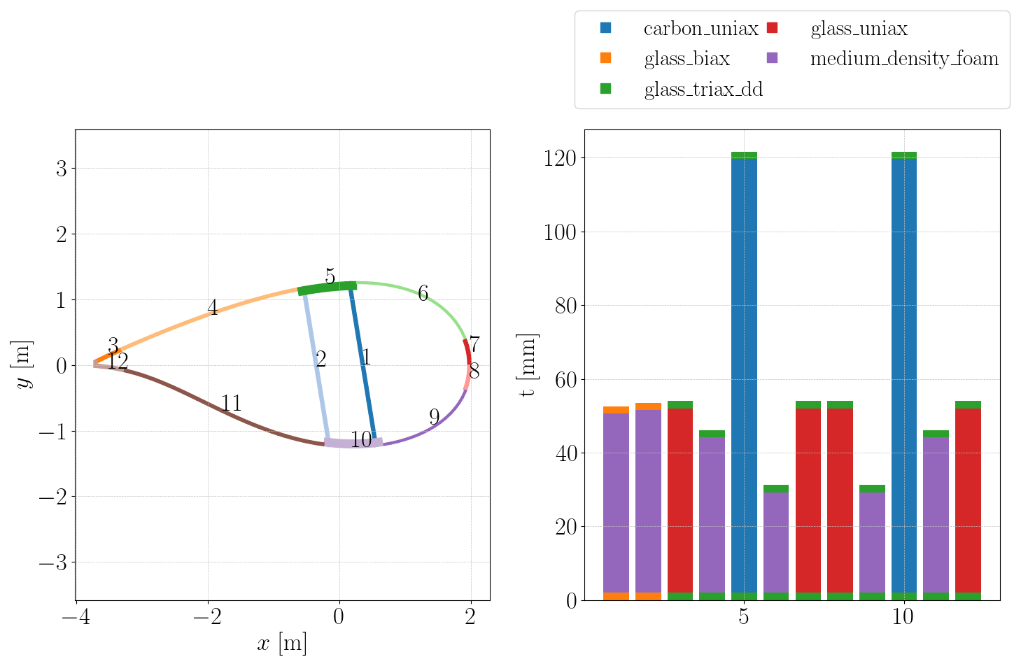
The section at 83 % span, shown in Fig. 26, illustrates the increasingly simplified structural layout of the blade as it approaches the tip. The introduction of foam at the leading and trailing edges reflects a modification incorporated into the CRC-15 blade to enhance local bending stiffness in a region where the UD glass is already tapered out. Notably, the foam cores are not reduced to their minimum allowable thickness, indicating their structural relevance in mass saving.
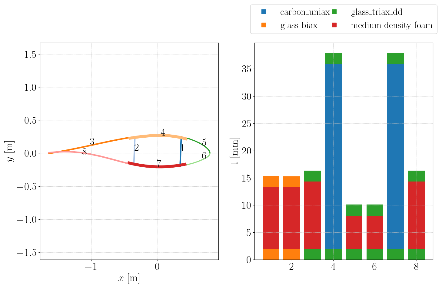
A key characteristic of the IEA-15-240 design is its material symmetry between the pressure and suction sides. Although the outer geometry is aerodynamically asymmetric, each upper-surface structural panel has a mirrored counterpart on the lower surface. Under asymmetric operational loading, particularly flapwise bending, the suction side experiences higher compressive stresses, and, therefore, buckling can become a critical factor in some areas, as reported in Ullah et al. (2020).
In the CRC simulations, the suction side governs structural sizing along the span due to the dominant compressive demand from bending. The spar caps are constrained by the peak flapwise moment, while the leading and trailing edges are governed by combined flapwise–edgewise load cases. The leading edge is placed in compression under the 150° moment orientation, whereas the trailing edge is compressed under the 30° orientation, which reverses the tension–compression distribution between the two regions.
In the CRC simulations, the suction side governs structural sizing along the span due to the dominant compressive demand from bending. The spar caps are constrained by the peak flapwise moment, while the leading and trailing edges are governed by combined flapwise–edgewise load cases. The leading edge is placed in compression under the 150° moment orientation, whereas the trailing edge is compressed under the 30° orientation, reversing the tension–compression distribution between the two regions.
Maximum strain is the primary sizing mechanism across most of the suction side, with compression-induced buckling becoming critical on the quarter-cylindrical shell at the leading edge and in some trailing-edge panels towards the rear of the blade. The tailored ±37° laminate finds a better compromise between these two failure modes than the triaxial lay-up: by reducing axial stiffness in the skin, it redistributes load more effectively towards the spar caps and edge reinforcements, which are better suited to carry it.
This work introduced a multi-parametric panel approach and incorporated it into the blade-optimization workflow, enabling sandwich panels to be represented as modular assemblies with independently parameterized materials. The formulation was verified through stiffness, load-path, and tapering consistency tests, establishing its suitability for applying continuous composite descriptions. This capability enabled the examination of DD laminates as viable replacements for conventional triaxial skins in a large-scale optimization setting.
The optimization of the CRC-15-240 blade using DD laminates on the shell resulted in a mass reduction of 4 % (2800 kg) compared to the baseline triaxial configuration, achieved through the substitution of the triaxial skins with a DD lay-up.
In general, 0° plies minimize spanwise strain, while 45° plies maximize buckling resistance. The optimized configuration strikes a compromise between these two demands, shifting the skin response from an axially stiff regime towards a softer one that better balances shear and buckling resistance against strain limits. This also redistributes axial stiffness from the shell to the spar caps and edge reinforcements, resulting in increased spar-cap thickness. In turn, the optimizer maximizes the structural contribution of the unidirectional carbon fiber, which offers superior strength-to-weight performance in the flapwise direction.
Beyond the spar caps, the suction-side shell emerged as the dominant sizing region. This area experienced the highest stress levels, particularly in compression, which were identified as the primary failure mode.
From a stiffness perspective, the aeroelastic response was only moderately affected. The most significant variations occurred near the blade root, where local mass reductions reached approximately 70 %. Despite these changes, all flapwise and edgewise displacements remained within the operational limits defined in Gaertner et al. (2020), confirming the structural viability of the optimized design.
From a manufacturing standpoint, the optimized DD skins integrate seamlessly into existing blade production practices. In a manner consistent with triaxial laminates, they can be assembled as repeating blocks, but with two selected fiber angles arranged according to the DD stacking pattern. This configuration remains fully compatible with current fabrics and vacuum-infusion processes and introduces no additional lay-up complexity. Consequently, the DD concept offers a practical approach to achieving weight savings while maintaining the established workflow used for conventional triaxial skins.
Future work
Several additional research directions naturally arise from this work. While the present study focused on preliminary investigations of DD laminates as a novel structural concept, future studies can evaluate its performance with higher-fidelity models and analyses, creating a basis for subsequent detailed design stages.
-
Fatigue modeling is a key area for further work. Although DD laminates are relatively new and lack extensive experimental data, their long-term cyclic performance remains uncertain. Future research should integrate fatigue degradation models into the optimization process and support experiments to characterize endurance. These data would allow direct fatigue constraints in the design space and, when needed, guide limits on allowable configurations. Nevertheless, preliminary tension–compression fatigue tests, such as those in Vasconcelos et al. (2025), indicate that DD laminates retain structural integrity under cyclic loading, supporting their long-term use.
-
Matrix-dominated damage mechanisms could be exhibited for the present DD case with ±37° since it lacks a third fiber orientation and is therefore not statically determined. A first study considering a constraint that enforces a minimum difference between the DD angles (here 30°) indicates a mass increase of 0.8t compared to the ±37° DD case while still maintaining a 2t mass advantage over the triax configuration. Further research on double-double laminates is needed to better understand their susceptibility to matrix-dominated damage mechanisms.
-
Through-thickness shear effects were incorporated into the buckling criterion in a simplified manner (k=1; see Fig. 4.4). A more rigorous treatment should adopt advanced lamination theories such as the first-order shear deformation theory (FSDT) or Mindlin–Reissner theory, which better capture shear deformation in thicker sandwich laminates. Additionally, the reference plane should be set to the mold surface rather than the mid-plane to improve the accuracy of the predicted bending stiffness.
-
Higher-fidelity strength criteria such as LaRC03 or Puck describe a physically based failure mechanism and capture specific mechanisms (e.g., matrix cracking).
-
A fully coupled aeroelastic analysis integrated into the optimization pipeline would enable more accurate prediction of stiffness-induced load redistribution. The current formulation assumes fixed aerodynamic loading and therefore does not capture secondary effects arising from skin softening or stiffness variation.
-
Extension stiffness:
-
Bending–extension stiffness:
-
Bending stiffness:
| Abbreviation | Description |
| AEP | Annual energy production |
| BB | Building block |
| CFRP | Carbon fiber reinforced plastic |
| CLT | Classical laminate theory |
| DD | Double-Double |
| DD-Hard | DD laminate with fixed 0° and variable Ψ |
| DD-Local | DD laminate with individualized angles per cross-section |
| IEA | International Energy Agency |
| RWT | Reference wind turbine |
| Triax | DD laminate with fixed 0°, 45° angles |
| UD | Unidirectional |
| Symbol | Description |
| [A] | Extensional stiffness matrix |
| [B*] | Coupling stiffness matrix normalized by laminate thickness |
| b | Panel width |
| [D] | Bending-stiffness matrix |
| Effective bending-stiffness term | |
| g | Constraint (e.g., stability, strength) |
| Gc | Shear modulus of sandwich core |
| k | Shear correction factor |
| kx, ks | Buckling coefficients (compression, shear) (Structural Analysis Working Group I, 2009) |
| m | Mass |
| Nx,cr, Nxy,cr | Critical buckling loads |
| nx | Uniaxial load |
| nxy | Shear load |
| [Q] | Ply stiffness matrix |
| r | Number of repeats |
| R | Ratio of applied to critical load |
| ρ | Density |
| σ1 | Normal stress |
| σ2 | Transverse normal stress |
| τ12 | Shear stress |
| tc | Sandwich core thickness |
| tlam | Thickness of the laminate |
| T | Total stack (following Nettles convention, Nettles, 1994) |
| TSAI | Trace of the ply stiffness matrix (Tr[Q]) |
| , , | Lamination parameters (Zerbst et al., 2025) |
| Wx | Trigonometric functions of ply angle θk |
| zk | Distance of the kth ply to the laminate mid-plane |
| α | Fraction of the Tsai modulus |
| θ | Ply angle orientation |
| ϕ, Φ | First Double-Double angle |
| ψ, Ψ | Second Double-Double angle |
The raw data required to reproduce these findings are available under the following repository: https://doi.org/10.5281/zenodo.17965770 (Werthen, 2025).
EW and GNR developed the methodology and software code, did the analyses, and wrote the paper. SD and LT supported the implementation of the approach into the lightworks framework. DZ and CH revised the paper and provided scientific supervision.
The contact author has declared that none of the authors has any competing interests.
Publisher's note: Copernicus Publications remains neutral with regard to jurisdictional claims made in the text, published maps, institutional affiliations, or any other geographical representation in this paper. The authors bear the ultimate responsibility for providing appropriate place names. Views expressed in the text are those of the authors and do not necessarily reflect the views of the publisher.
We would like to acknowledge the funding by the Deutsche Forschungsgemeinschaft (DFG, German Research Foundation) under Germany´s Collaborative Research Center – CRC 1463/2 - Integrated design and operation methodology for offshore megastructures – project ID no. 434502799.
This research has been supported by the Deutsche Forschungsgemeinschaft (grant no. 434502799).
The article processing charges for this open-access publication were covered by the German Aerospace Center (DLR).
This paper was edited by Julie Teuwen and reviewed by three anonymous referees.
Almeida, J. H. S., Balonek, E., and Castro, S. G.: Beyond Double-Double theory: n-Directional stacking sequence optimisation in composite laminates, Compos. Struct., 373, 119586, https://doi.org/10.1016/j.compstruct.2025.119586, 2025. a
Amabili, M.: Composite, Sandwich and Functionally Graded Materials: Advanced Nonlinear Shell Theories, Cambridge University Press, 90–123, 2018. a
Bak, C., Zahle, F., Bitsche, R., Kim, T., Yde, A., Henriksen, L., Hansen, M., Blasques, J., Gaunaa, M., and Natarajan, A.: The DTU 10-MW Reference Wind Turbine, DTU Wind Energy, Technical University of Denmark, DTU Wind Energy Report-I-0092, 138 pp., https://rwt.windenergy.dtu.dk/dtu10mw/dtu-10mw-rwt (last access: 24 June 2026), 2013. a
Bortolotti, P., Tarrés, H., Dykes, K., Merz, K., Sethuraman, L., Verelst, D., and Zahle, F.: IEA Wind TCP Task 37: Systems Engineering in Wind Energy-WP2.1 Reference Wind Turbines, National Renewable Energy Laboratory (NREL), https://doi.org/10.2172/1529216, 2019. a
Bortolotti, P., Bay, C., Barter, G., Gaertner, E., Dykes, K., McWilliam, M., Friis-Moller, M., Pedersen, M. M., and Zahle, F.: System Modeling Frameworks for Wind Turbines and Plants: Review and Requirements Specifications, Tech. rep., NREL/TP-5000-82621, National Renewable Energy Laboratory (NREL), https://doi.org/10.2172/1868328, 2022. a
Camarena, E., Anderson, E., Paquette, J., Bortolotti, P., Feil, R., and Johnson, N.: Land-based wind turbines with flexible rail-transportable blades – Part 2: 3D finite element design optimization of the rotor blades, Wind Energ. Sci., 7, 19–35, https://doi.org/10.5194/wes-7-19-2022, 2022. a, b, c
Castro, O.: Fatigue strength of composite wind turbine blade structures, PhD thesis, DTU Wind Energy, Denmark, https://doi.org/10.11581/00000037, 2018. a
Couto, L. d. L., Moreira, N. E., Saito, J. Y. d. O., Hallak, P. H., and Lemonge, A. C. d. C.: Multi-Objective Structural Optimization of a Composite Wind Turbine Blade Considering Natural Frequencies of Vibration and Global Stability, Energies, 16, https://doi.org/10.3390/en16083363, 2023. a, b
Dähne, S., Werthen, E., Zerbst, D., Tönjes, L., Traub, H., and Hühne, C.: Lightworks, a scientific research framework for the design of stiffened composite-panel structures using gradient-based optimization, Struct. Multidiscip. O., 67, 70, https://doi.org/10.1007/s00158-024-03783-1, 2024. a
Daniel, I., Werner, B., and Fenner, J.: Strain-rate-dependent failure criteria for composites, Compos. Sci. Technol., 71, 357–364, https://doi.org/10.1016/j.compscitech.2010.11.028, 2011. a
DNV GL: DNVGL-ST-0376: Rotor Blades for Wind Turbines, Standard, Proposal No. 2015-218, Final Draft for Hearing, DNV GL Renewables Certification, 2015. a, b, c, d
Gaertner, E., Rinker, J., Sethuraman, L., Zahle, F., Anderson, B., Barter, G., Abbas, N., Meng, F., Bortolotti, P., Skrzypinski, W., Scott, G., Feil, R., Bredmose, H., Dykes, K., Sheilds, M., Allen, C., and Viselli, A.: Definition of the IEA 15-Megawatt Offshore Reference Wind Turbine, Tech. rep., NREL/TP-5000-75698, International Energy Agency, https://doi.org/10.2172/1603478, 2020. a, b, c
Garofano, A., Sellitto, A., Acanfora, V., Di Caprio, F., and Riccio, A.: On the effectiveness of double-double design on crashworthiness of fuselage barrel, Aerosp. Sci. Technol., 140, 108479, https://doi.org/10.1016/j.ast.2023.108479, 2023. a
Gasch, R. and Twele, J.: Wind Power Plants: Fundamentals, Design, Construction and Operation, Springer Berlin Heidelberg, Berlin, Heidelberg, 2nd edn., ISBN 978-3-642-22937-4, 2012. a
Hayat, K., Siddique, S., Sultan, T., Ali, H. T., Aloufi, F. A., and Halawani, R. F.: Effect of Spar Design Optimization on the Mass and Cost of a Large-Scale Composite Wind Turbine Blade, Energies, 15, https://doi.org/10.3390/en15155612, 2022. a, b, c
Industrie Ausschuss Struktur Berechnungsunterlagen (IASB): Luftfahrttechnisches Handbuch (LTH): Handbuch für Strukturberechnung (HSB), IASB, München, Germany, 2009. a, b
Jung, S. and Nagaraj, V. T.: Structural Behavior of Thin- and Thick-Walled Composite Blades with Multi-Cell Sections, in: 43rd AIAA/ASME/ASCE/AHS/ASC Structures, Structural Dynamics, and Materials Conference, American Institute of Aeronautics and Astronautics, AIAA 2002-1432, https://doi.org/10.2514/6.2002-1432, 2002. a
Kappel, E.: Double–Double laminates for aerospace applications – Finding best laminates for given load sets, Composites Part C: Open Access, 8, 100244, https://doi.org/10.1016/j.jcomc.2022.100244, 2022. a
Kappel, E.: On invariant combinations of Qij coefficients and a novel invariant IQ, Composites Part C: Open Access, 10, 100335, https://doi.org/10.1016/j.jcomc.2022.100335, 2023. a
Kappel, E. and Tsai, S. W.: Double-Double Laminates – A Review on the Status Quo in Spring 2024, Tech. rep., DLR (German Aerospace Center), https://doi.org/10.57965/g2cb-8t21, 2024. a
Kassapoglou, C.: Design and Analysis of Composite Structures, Wiley, https://doi.org/10.1002/9781118536933, 2013. a, b
Liu, P. and Barlow, C. Y.: Wind turbine blade waste in 2050, Waste Management, 62, 229–240, https://doi.org/10.1016/j.wasman.2017.02.007, 2017. a
Nettles, A. T.: Basic mechanics of laminated composite plates, Tech. rep., National Aeronautics and Space Administration, Huntsville, AL, United States, George C. Marshall Space Flight Center, https://www.osti.gov/biblio/6880327 (last access: 23 June 2026), 1994. a, b
Peters, R. W.: Buckling of Long Square Tubes in Combined Compression and Torsion and Comparison with Flat-plate Buckling Theories, Technical Note NACA-TN-3184, National Advisory Committee for Aeronautics (NACA), NTRS Document ID: 19930083964, https://ntrs.nasa.gov/citations/19930083964 (last access: 23 June 2026), 1954. a
Riccio, A., Caprio, F. D., Tsai, S., Russo, A., and Sellitto, A.: Optimization of composite aeronautical components by Re-designing with double-double laminates, Aerosp. Sci. Technol., 151, 109304, https://doi.org/10.1016/j.ast.2024.109304, 2024. a
Rinker, J. and Dykes, K. L.: WindPACT Reference Wind Turbines, Tech. rep., National Renewable Energy Laboratory (NREL), Golden, CO, United States, https://doi.org/10.2172/1432194, 2018. a
Rinker, J., Gaertner, E., Zahle, F., Skrzypiński, W., Abbas, N., Bredmose, H., Barter, G., and Dykes, K.: Comparison of loads from HAWC2 and OpenFAST for the IEA Wind 15 MW Reference Wind Turbine, J. Phys. Conf. Ser., 1618, 052052, https://doi.org/10.1088/1742-6596/1618/5/052052, 2020. a
Rosemeier, M. and Krimmer, A.: Rotorblattstruktur, in: Einführung in die Windenergietechnik, edited by: Schaffarczyk, A. P., Carl Hanser Verlag GmbH & Co. KG, 3rd edn., Chap. 5, 169–220, https://doi.org/10.1007/978-3-446-47322-5, ISBN 9783446473225, 2022. a
Samborsky, D. D. and Mandell, J. F.: Fatigue resistant fiberglass laminates for wind turbine blades, American Society of Mechanical Engineers (ASME), New York, NY, United States, OSTI ID: 372115, https://www.osti.gov/biblio/372115 (last access: 23 June 2026), 1996. a
Scott, S., Greaves, P., Macquart, T., and Pirrera, A.: Comparison of blade optimisation strategies for the IEA 15MW reference turbine, J. Phys. Conf. Ser., 2265, 032029, https://doi.org/10.1088/1742-6596/2265/3/032029, 2022. a, b, c, d
Serafeim, G. P., Manolas, D. I., Riziotis, V. A., Chaviaropoulos, P. K., and Saravanos, D. A.: Optimized blade mass reduction of a 10MW-scale wind turbine via combined application of passive control techniques based on flap-edge and bend-twist coupling effects, J. Wind Eng. Ind. Aerod., 225, 105002, https://doi.org/10.1016/j.jweia.2022.105002, 2022. a
Sjølund, J. H. and Lund, E.: Structural Gradient-Based Sizing Optimization of Wind Turbine Blades with Fixed Outer Geometry, Compos. Struct., 203, 725–739, https://doi.org/10.1016/j.compstruct.2018.07.031, 2018. a, b, c
Tsai, S. W.: Double–Double: New Family of Composite Laminates, AIAA J., 59, 4293–4305, https://doi.org/10.2514/1.J060659, 2021. a, b, c, d, e, f, g, h, i
Tsai, S. W. and Melo, J. D. D.: Composite Materials Design and Testing: Unlocking Mystery with Invariants, Stanford Aeronautics & Astronautics, ISBN 9780986084515, https://books.google.de/books?id=pLxsrgEACAAJ (last access: 23 June 2026), 2015. a, b
Ullah, H., Ullah, B., and Silberschmidt, V. V.: Structural integrity analysis and damage assessment of a long composite wind turbine blade under extreme loading, Compos. Struct., 246, 112426, https://doi.org/10.1016/j.compstruct.2020.112426, 2020. a
Vasconcelos, T. B., Alves, J. L. C., da Costa Ferreira, E. P., Júnior, R. C. S. F., and Melo, J. D. D.: Static and fatigue behavior of double-double glass/epoxy laminates, J. Compos. Mater., 59, 119–133, https://doi.org/10.1177/00219983241261065, 2025. a
Verein Deutscher Ingenieure (VDI): Faserverbundwerkstoffe: Berechnung und Anwendung von Faserverbundstrukturen, 1. Auflage, VDI Verlag GmbH, VDI 2014 Blatt 3, 158 pp., https://www.vdi.de/ (last access: 23 June 2026), 2014. a
Werthen, E.: CRC1463 Blade designs with double-double laminates for the CRC15-240 turbine, Version v1, Zenodo, https://doi.org/10.5281/zenodo.17965770, 2025. a
Werthen, E., Ribnitzky, D., Zerbst, D., Kühn, M., and Hühne, C.: Aero-structural coupled optimization of a rotor blade for an upscaled 25 MW reference wind turbine, J. Phys. Conf. Ser., 2626, 012012, https://doi.org/10.1088/1742-6596/2626/1/012012, 2023. a, b, c, d, e
Werthen, E., Hardt, D., Balzani, C., and Hühne, C.: Comparison of different cross-sectional approaches for the structural design and optimization of composite wind turbine blades based on beam models, Wind Energ. Sci., 9, 1465–1481, https://doi.org/10.5194/wes-9-1465-2024, 2024. a
Zahle, F., Barlas, A., Lønbæk, K., Bortolotti, P., Zalkind, D., Wang, L., Labuschagne, C., Sethuraman, L., and Barter, G.: Definition of the IEA Wind 22-Megawatt Offshore Reference Wind Turbine, Tech. Rep. DTU Wind Report E-0243, Technical University of Denmark, https://doi.org/10.11581/DTU.00000317, ISBN 978-87-87335-71-3, 2024. a, b
Zerbst, D., Tönjes, L., Dähne, S., Werthen, E., Kappel, E., and Hühne, C.: Equivalent plate formulation of Double–Double laminates for the gradient-based design optimization of composite structures, Compos. Struct., 354, 118786, https://doi.org/10.1016/j.compstruct.2024.118786, 2025. a, b, c, d, e, f
Zhao, K., Kennedy, D., Miravete, A., Tsai, S. W., Featherston, C. A., and Liu, X.: Defining the Design Space for Double–Double Laminates by Considering Homogenization Criterion, AIAA J., 61, 3190–3203, https://doi.org/10.2514/1.J062639, 2023. a
Short for “Lightworks for Wind”
- Abstract
- Introduction
- Characterization of DD and triaxial laminates
- Multi-parametric composites
- CRC-15-240 blade optimization
- Results
- Conclusions
- Appendix A: Derivation of plane-shifted stiffness matrices
- Appendix B: List of symbols and abbreviations
- Data availability
- Author contributions
- Competing interests
- Disclaimer
- Acknowledgements
- Financial support
- Review statement
- References
- Abstract
- Introduction
- Characterization of DD and triaxial laminates
- Multi-parametric composites
- CRC-15-240 blade optimization
- Results
- Conclusions
- Appendix A: Derivation of plane-shifted stiffness matrices
- Appendix B: List of symbols and abbreviations
- Data availability
- Author contributions
- Competing interests
- Disclaimer
- Acknowledgements
- Financial support
- Review statement
- References