the Creative Commons Attribution 4.0 License.
the Creative Commons Attribution 4.0 License.
 | 24 Apr 2023
Prognostics-based adaptive control strategy for lifetime control of wind turbines
Edwin Kipchirchir
M. Hung Do
Jackson G. Njiri
Dirk Söffker
Variability in wind profiles in both space and time is responsible for fatigue loading in wind turbine components. Advanced control methods for mitigating structural loading in these components have been proposed in previous works. These also incorporate other objectives like speed and power regulation for above-rated wind speed operation. In recent years, lifetime control and extension strategies have been proposed to guarantee power supply and operational reliability of wind turbines. These control strategies typically rely on a fatigue load evaluation criteria to determine the consumed lifetime of these components, subsequently varying the control set point to guarantee a desired lifetime of the components. Most of these methods focus on controlling the lifetime of specific structural components of a wind turbine, typically the rotor blade or tower. Additionally, controllers are often designed to be valid about specific operating points and hence exhibit deteriorating performance in varying operating conditions. Therefore, they are not able to guarantee a desired lifetime in varying wind conditions. In this paper an adaptive lifetime control strategy is proposed for controlled aging of rotor blades to guarantee a desired lifetime while considering damage accumulation level in the tower. The method relies on an online structural health monitoring system to vary the lifetime controller gains based on a state-of-health (SoH) measure by considering the desired lifetime at every time step. For demonstration, a 1.5 MW National Renewable Energy Laboratory (NREL) reference wind turbine is used. The proposed adaptive lifetime controller regulates structural loading in the rotor blades to guarantee a predefined damage level at the desired lifetime without sacrificing the speed regulation performance of the wind turbine. Additionally, a significant reduction in the tower fatigue damage is observed.
- Article
(4731 KB) - Full-text XML
- BibTeX
- EndNote


Growing demand for wind energy has led to the development of large wind turbines. However, these turbines are less tolerant to system performance degradation and faults (Gao and Liu, 2021). To ensure utility-scale wind turbines operate with respect to their design lifetime, advanced control strategies have been developed in recent years to reduce structural loading of blades and the tower. Most of these incorporate additional objectives such as power optimization and rotor speed regulation. The objective of the lifetime control of wind turbines using prognostics-based load mitigation strategies has become more important in recent years. Most of the proposed methods focus on controlling the lifetime of one structural component of a wind turbine, typically the rotor blade or the tower, without considering the fatigue damage level in other components. These lifetime controllers are also designed to be valid regarding specific operating points.
A control strategy for extending the maintenance interval of wind turbine blades under assumed crack initiation, detected using a data filtering algorithm, is proposed (Beganovic et al., 2015). In Beganovic et al. (2018) and Njiri et al. (2019), a set of switching controllers with varying degrees of load mitigation are engaged sequentially based on the accumulated damage obtained from an online damage evaluation model to extend the lifetime of rotor blades. An adaptive lifetime controller is proposed in Do and Söffker (2020) to guarantee the desired lifetime of the tower. Depending on the damage accumulation and the predicted lifetime provided by an online damage evaluation model, the weights of the lifetime controller are varied. However, in Beganovic et al. (2015), Beganovic et al. (2018), Njiri et al. (2019), and Do and Söffker (2020), fatigue damage is considered in only one turbine component. The lifetime controllers used are not adaptive to varying wind conditions. In recent times, resilient control has been proposed in Acho et al. (2016), Azizi et al. (2019), El Maati and El Bahir (2020), and Jain and Yamé (2020) to minimize the effect of unanticipated faults or unexpected dynamics to maintain the operation of a wind turbine within a limited degradation tolerance bound. However, resilient control does not address the problem of controlling life consumption in wind turbine components to avoid early fatigue failures. Although new concepts like operational modal analysis (OMA), which relies on measurement data to analyze vibrating structures, are becoming the industry standard for condition monitoring and diagnosis especially for offshore wind turbines (Kim et al., 2019; Bajrić et al., 2018; Dong et al., 2018; Pegalajar-Jurado and Bredmose, 2019), these concepts have yet to be integrated for prognosis and lifetime control of wind turbines.
In this work an adaptive lifetime control strategy is proposed for controlling the aging of rotor blades to guarantee a desired lifetime while considering damage accumulation level in the tower. A robust disturbance accommodating control (RDAC) proposed in Do and Söffker (2022) is used for rotor speed regulation and load mitigation in the tower, while a prognostics-based adaptive independent pitch control (aIPC), which adapts to wind speed variation, is used for lifetime control of rotor blades. By monitoring the accumulated damage using an online structural health evaluation model, the load mitigation level in the blades is controlled by varying the control gains in the respective IPC controllers based on a threshold evaluation of the estimated lifetime. As an improvement to the approaches in the aforementioned contributions, the proposed adaptive lifetime control strategy regulates fatigue loading in the rotor blades to reach a predefined damage limit at the desired lifetime with subsequent reduction in tower damage accumulation. This is realized without trade-off in speed and power regulation performance. Although the proposed lifetime control strategy is applied to wind turbine operations in above-rated operation, this concept can be extended for lifetime control in below-rated operation with suitable objectives including reducing structural loads while ensuring maximum power extraction as proposed in Do and Söffker (2020).
The paper is organized as follows. In Sect. 2, a theoretical background on wind turbine health monitoring is given. In Sect. 3, the design of the primary RDAC for rotor speed regulation and tower load mitigation, as well as the prognostics-based aIPC lifetime controller for controlled aging of rotor blades, is outlined. The proposed prognostics-based adaptive lifetime control strategy, which incorporates the primary and lifetime controllers, as well as an online damage evaluation model, is described in Sect. 4. In Sect. 5, simulation results based on the performance evaluation of the proposed prognostics-based adaptive lifetime control strategy on a reference wind turbine are discussed. Lastly, a summary and conclusions are given in Sect. 6.
Wind speed variability subjects wind turbine components like blades and the tower to cyclic loading. This causes damage to be accumulated in these components over time causing gradual degradation until failure occurs. Therefore, structural health monitoring of wind turbines is important in preventing the occurrence of fatigue failure before reaching the related design lifetime. Information on the damage evolution in a component can be utilized as a health indicator for failure detection, as well as for developing control measures to guarantee the desired lifetime. This section outlines the methods used for estimating the damage accumulation in wind turbine components.
2.1 Evaluation of damage accumulation
A wind turbine endures varying and complex load conditions over its lifetime. Fatigue analysis is therefore important in determining the consumed lifetime of its components. Component degradation starts at microscale as micro-cracks resulting from irreversible changes in the microstructure and propagates gradually until it fails. Assumptions of underlying damage evolution laws are often used to estimate the actual damage level, as well as to predict the remaining useful life (RUL) of a component. Component-specific high-cycle fatigue experiments are used to generate S–N curves (Wöhler curve), which describe the relationship between applied stress amplitude S and the number of load cycles N that would cause failure. This forms the basis for the mathematical relation for fatigue analysis in wind turbine components expressed as
where s denotes the stress range amplitude and m the Wöhler exponent (typically 3 for steel materials like the tower and 10 for composites like the blade; Ragan and Manuel, 2007). The material parameter of fatigue damage at failure K, e.g., ultimate tensile strength, is related to the number of load cycles N.
Wind turbine components are designed for a service lifetime of at least 20 years according to the International Electrotechnical Commission (IEC) standard, with these structural components facing roughly between 108 and 109 fatigue load cycles (Ziegler et al., 2018). The component lifetime is typically arrived at using the projected number of fatigue cycles and average wind conditions it will encounter in its lifetime. Additionally, the IEC standard specifies that a wind turbine component should be designed to maintain its structural integrity in case it experiences 50-year extreme wind events during its lifetime.
Fatigue damage in components can be assessed using linear damage accumulation theory based on Miner's rule or nonlinear damage accumulation theories (Yuan et al., 2015). Due to its simplicity, Miner's rule (Miner, 1945) is widely used. Wind speed variability induces a varying-amplitude load spectrum on wind turbine components. To use Miner's rule, the complex spectrum of varying load is often transformed using the rain-flow counting (RFC) algorithm first proposed by Matsuishi and Endo (1968) into simple uniform loading, from which stress range histograms can be extracted and used to assess the accumulated damage. A schematic of this procedure is shown in Fig. 1.
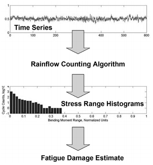
By combining RFC and Miner's rule, damage accumulation Dk is calculated as
where k denotes the total number of related stress range histograms, di the incremental damage at the ith stress range histogram, ni the number of applied load cycles in each histogram bin, Ni the number of cycles to failure at the ith stress range histogram, and si the applied load amplitude in each histogram bin. With continual load application, damage in a component progresses from an undamaged state Dk=0 to the point it is considered to have reached its end of life when the accumulated damage Dk=1. In this case, the component is considered to have exhausted its structural reserves. Although other cycle counting algorithms including level crossing counting, peak counting, and simple range counting exist, RFC algorithms are the most widely applied for fatigue analysis (Musallam and Johnson, 2012).
2.2 Online rain-flow counting
Most standard RFC algorithms generate equivalent load cycles from complex load spectra by pairing local minimum and maximum points using the three-point counting rule. Therefore, the entire load history is needed beforehand for the equivalent cycles to be generated. This process is computationally inefficient because the algorithm has to process all the stored loading data. Therefore, standard RFC cannot be used for real-time monitoring or control of life consumption of a component (Musallam and Johnson, 2012).
In Musallam and Johnson (2012), a real-time implementation of the RFC algorithm is proposed. By employing a three-point counting rule recursively, the extremal points of time-series loading data are processed and stored in two flexible stacks as they occur to pick out the full and half cycles. For each identified cycle and using Miner's rule, the life consumption of a component is then calculated and incremented online. This allows for the online determination of the consumed life of a component, as well as implementation of lifetime control. In this paper, the online damage evaluation algorithm (Musallam and Johnson, 2012) is adopted for evaluating the accumulated damage in rotor blades and the tower. This information is then used to adapt the lifetime controller to guarantee a predefined service life of the wind turbine components.
In this paper, the robust disturbance accommodating controller (RDAC) (Do and Söffker, 2022), proposed for rotor speed regulation and mitigation of tower fore–aft bending moments, is extended to include an adaptive independent pitch controller (aIPC), which is used as a dynamic lifetime controller for reducing blade flapwise bending moments in a wind turbine operating in an above-rated wind speed region. In this section the description of the reference wind turbine (RWT) is outlined. Additionally, the description of the adaptive robust observer-based controller, which is adapted for lifetime control, is summarized.
3.1 Wind turbine model description
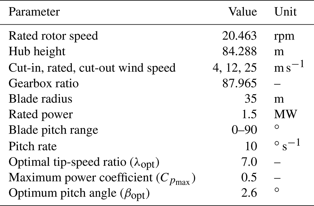
A 1.5 MW WindPACT reference wind turbine developed by the National Renewable Energy Laboratory (NREL) (Rinker and Dykes, 2018), which is available in fatigue, aerodynamics, structures, and turbulence (FAST) design code (Jonkman and Buhl, 2005), is chosen as the test bed for the design and simulation of the proposed adaptive lifetime control strategy. This onshore wind turbine model was developed based on a real-life commercial wind turbine used in the WindPACT program. The specifications of this turbine are summarized in Table 1. It is a three-bladed, upwind, horizontal-axis wind turbine, having 24 degrees of freedom (DoFs) describing its flexibility. However, a few DoFs are enabled to obtain reduced-order linear-time-invariant (LTI) models used for controller design.
Table 1The 1.5 MW WindPACT reference wind turbine specifications.
The nonlinear generalized equation of motion for the wind turbine is expressed as
where M denotes the mass matrix containing inertia and mass components and f is a nonlinear function of the enabled DoFs q and their first derivative , as well as the control input u, the disturbance input ud, and time t. The nonlinear model Eq. (3) available in FAST is linearized with respect to an operating point in the above-rated region. By enabling the DoFs, which capture the most important wind turbine dynamics of interest, and specifying the operating point defined by a constant hub-height wind speed, pitch angle, and rotor speed, linearization is carried out numerically in FAST yielding periodic (azimuth-dependent) matrices of LTI models.
3.2 Controller for load mitigation and speed regulation
An adaptive robust observer-based controller, which in combination with an online damage evaluation model used for lifetime control of wind turbine components, is briefly outlined.
3.2.1 Robust disturbance accommodating controller
The RDAC, proposed in previous work (Do and Söffker, 2022), is briefly outlined for principal understanding. To obtain an LTI model for controller design while avoiding unnecessary complexity in the linear model, six DoFs including tower fore–aft bending in first mode; drivetrain torsional displacement; blades 1, 2, and 3 flapwise displacements in first mode; variable speed generator; and drivetrain rotational flexibility are chosen. These DoFs capture the most important dynamics corresponding to the desired closed-loop performance with respect to load mitigation in wind turbine blades and the tower, as well as generator speed regulation assuming also a flexible drivetrain. The linear model is obtained by linearizing the nonlinear model Eq. (1) with respect to an operating point in the above-rated wind speed region defined by a steady hub-height wind speed of vop=18 m s−1, a pitch angle of βop=20∘, and a rotor speed of ωop=20.463 rpm. The states x used for controller design are
The obtained reduced-order LTI model is expressed in state-space form as
where , and C denote the state-space system; u the control input, which is the collective pitch angle; x the states; d the wind disturbance; and y the measured outputs, which include rotor speed and tower-top fore–aft bending moment.
The model Eq. (5) is augmented with a pitch actuator model, which accounts for the slow pitch actuator dynamics. To counteract wind disturbance effects, the model is extended with an assumed step disturbance waveform (Wright, 2003; Wright and Fingersh, 2008), which approximates sudden uniform rotor effective wind velocity fluctuations. To meet the rotor speed regulation objective with zero steady-state tracking error, the model is further extended with a partial integral action.
To ensure closed-loop system stability, robustness, and optimality, a mixed-sensitivity H∞ norm of the closed loop transfer function is used as a cost function to optimize the disturbance accommodating controller (DAC) parameters including observer gain Lx, state controller Kx, disturbance rejection controller Kd, and the integral gain Ki in a single step. The mixed sensitivity H∞ optimization problem is formulated as
where R* denotes the optimized controller and ℛ a set of controllers R that stabilize the plant. The weighting functions W1, W2, and W3 are introduced to ensure desired robust performance, while S, RS, and T denote the related sensitivity, control effort, and complementary sensitivity functions, respectively. The problem to find an optimal RDAC, RDAC*, is formulated as
where ℛ𝒟𝒜𝒞 denotes a set of controllers RDAC that stabilize the generalized plant P, and Gzd is the transfer function from the exogenous inputs d to the controlled outputs z.
Nonsmooth H∞ synthesis proposed in Apkarian and Noll (2006), used for problems with structural and stability constraints, is applied to find an optimal controller RDAC* with robust gains L and K for tower load mitigation and rotor speed regulation. It is implemented in MATLAB using the hinfStruct command (Apkarian and Noll, 2017). In Fig. 2 the application of the RDAC to the 1.5 MW NREL RWT is shown. An actuator transfer function is included in the generalized plant P, to account for the blade pitch actuator dynamics. Hub-height wind disturbance d excites the wind turbine dynamics in above-rated operation. Measurement outputs including rotor speed ω and tower fore–aft bending moment ζ are fed to the RDAC, which generates a collective pitch angle β as a control signal for regulating rotor speed at the rated value and for reducing tower fore–aft bending moment oscillations. The RDAC is robust against modeling errors and wind disturbances. The desired trade-off between robust stability and performance is achieved by choosing suitable weighting functions W11, W12, and W2. To effect rotor speed response and ensure robustness against wind disturbances, W11 is designed as an inverted low-pass filter. To reduce the first mode of tower fore–aft oscillation, W12 is designed as an inverted notch filter centered at 2.56 rad s−1. To reduce controller activity at high frequencies thereby increasing robustness, W2 is chosen as the high-pass filter.

Both objectives of rotor speed regulation and tower load reduction for wind turbines operating in an above-rated wind speed region are met while ensuring robustness against modeling errors and wind disturbances. However, RDAC* is only valid within its design operating point and suffers performance deterioration outside this envelop. Additionally, its control input signal is a collective pitch angle, hence cannot be applied for reducing blade oscillations due to vertical wind shear, which can only be achieved through IPC.
3.2.2 Adaptive independent pitch controller
This controller is desired to counteract periodic aerodynamic loading of the rotor blades due to vertical wind shear. It is designed to reduce 1P (once per revolution; 0.333 Hz) blade flapwise oscillations and is adaptive to change in the operating point due to horizontal wind speed fluctuations. Five IPC controllers, each designed to be operational over a particular wind speed bin in the above-rated wind speed region, together with a switching mechanism based on the incoming wind speed, are used to realize aIPC. The linear models, used for designing respective IPC controllers, are extracted from the nonlinear wind turbine model Eq. (1) at different operating points as shown in Table 2. It is important to note that the steady wind speeds (together with associated pitch angle and rated rotor speed) are only used to define operating points for extracting linear state-space models used for designing each of the IPC controllers. However, a stochastic wind profile is used for excitation of the closed-loop dynamic response of the wind turbine. Predefined wind speed bins are only used for thresholding based on the incoming hub-height stochastic wind speed to establish the appropriate IPC controller to be utilized in continuous operation.

To capture the most important dynamics with respect to blade load mitigation and speed regulation, four DoFs including blade flapwise displacement for each blade in the first mode and variable speed generator are chosen. Correspondingly, seven states x are included in the linear model used for designing the aIPC controller. To capture periodicity due to vertical wind shear, 24 equispaced azimuth positions are selected for linearization. To integrate this periodicity in controller design, multi-blade coordinate (MBC) transformation proposed in Bir (2010) is used to transform blade dynamics from the rotating to the non-rotating frame. The MBC-transformed reduced-order models are then averaged to obtain a weakly periodic LTI model described in state-space form as
where , and C denote the state-space system, u=[Δβ1Δβ2Δβ3]T denotes the perturbed independent pitch angles, and d is the wind disturbance. The measurements y, which include the blade root flapwise bending moment for each blade, are assumed to be distorted with noise v.
Using a linear quadratic Gaussian (LQG) control method, Eq. (8) is used to design an observer-based controller. The full-state feedback controller K is designed using a linear quadratic regulator (LQR) technique by minimizing the cost function:
while solving the algebraic Riccati equation (ARE) , assuming (A,B) is fully controllable. Here Q and R denote the state and control input weighting matrices, respectively, whose elements are tuned to achieve the desired dynamic response with respect to blade load mitigation and rotor speed regulation, while P is the solution to the ARE. To implement optimal full-state feedback control using estimated states , a Kalman state estimator is used to design the observer gain L by minimizing the state estimation covariance error while solving the ARE , assuming (A, C) is fully observable. Here, Qf and Rf are process disturbance and measurement noise covariance matrices, respectively, while Pf is the solution to the ARE.
Figure 3 illustrates the implementation of one of the five IPC controllers. The wind profile d excites the dynamics of the wind turbine in the above-rated wind speed region. The perturbed blade root flapwise bending moment measurements Δy are transformed from the rotating to the fixed coordinate frame of controller design using an inverse MBC transformation matrix T(ψ)−1, which relies on real-time rotor azimuth angle measurements ψ. The perturbed independent pitch angles Δβi are obtained by transforming the control input u back to the rotating frame using the MBC transformation matrix T(ψ). By summing Δβi and the collective pitch angle βc from the RDAC, the IPC signal βi is obtained.
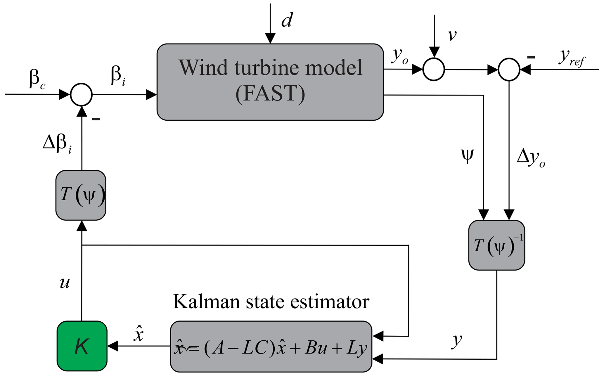
The five IPC controllers are designed following this procedure, each at a predefined operating point, to cover the entire range of operation in the above-rated regime. A switching mechanism is implemented to activate each controller at a predefined operating range based on the incoming hub-height wind speed for system excitation using a stochastic wind profile.
To control the lifetime consumption in wind turbine blades, the adaptive robust observer-based controller (RDAC+aIPC), implemented using two control loops, is combined with an online damage evaluation model as shown in Fig. 4. A wind profile excites the wind turbine dynamics in the above-rated regime. The RDAC (Do and Söffker, 2022), which is robust against modeling errors generates the primary collective pitch controller (CPC) signal for rotor speed regulation and tower load mitigation, while aIPC is used as the lifetime controller to dynamically control the damage accumulation of the rotor blades. The IPC angles are perturbed with respect to the CPC signal from RDAC, forming the control input u to the wind turbine.
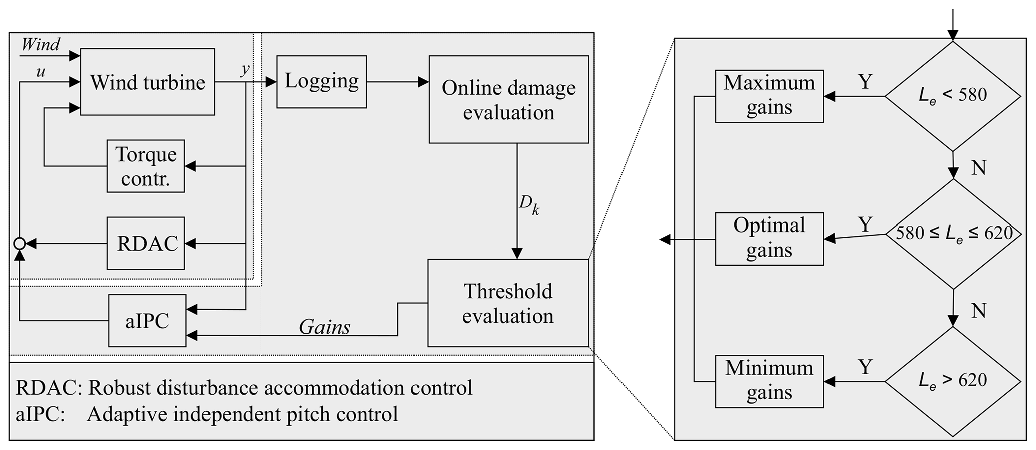
The blade-root flapwise bending moment measurements y are logged into memory during simulation. The online damage evaluation model based on the real-time implementation of the RFC algorithm (Musallam and Johnson, 2012) calculates the accumulated damage at every time step Dk. The estimated lifetime of the blade Le used as a state-of-health (SoH) indicator is calculated as
where Tk denotes the current time step, while Dd denotes the accumulated damage at the design lifetime. At every time step Tk, the estimated RUL can be calculated as
Based on the threshold evaluation of Le, the load mitigation level in the respective IPC controllers is controlled by selecting the appropriate gains L and K every 10 ms, which is the time interval chosen for lifetime threshold evaluation. For illustrative purposes a lifetime of 600 s is chosen. Three threshold levels are set such that if Le is below the lower limit of the desired lifetime (Le < 580), maximum gains of respective IPC controllers are selected to increase the blade load mitigation level. If Le falls within a range of the desired lifetime (), optimum gains, which strike a balance between load mitigation and speed regulation, are selected. On the other hand, if the value of Le is higher than the desired lifetime (Le > 620) and hence blade load mitigation level can be compromised, minimum gains are chosen.
It is important to note that two levels of switching are implemented as illustrated in Fig. 5. The first level, used for switching between different IPC controllers, is defined based on the incoming hub-height stochastic wind speed. Highly uncertain wind turbine anemometer measurements should suffice, as strict accuracy is not required for switching. Predefined wind speed bins are used for thresholding and activating a suitable IPC controller from the designed bank of controllers. This ensures that an appropriate IPC controller is used for the prevailing operating conditions. The second level of switching relies on a lifetime estimate of the blades obtained from the online damage evaluation model to adapt both the full-state feedback gain K and observer gain L of the IPC controller activated in the first level of switching to achieve the targeted lifetime. The combined switching constitutes aIPC lifetime control.

This section presents and discusses the simulation results obtained from evaluating the adaptive lifetime control strategy using the 1.5 MW NREL RWT in FAST design code. Following the IEC 61400-1 recommendation for fatigue load evaluation, a 600 s stochastic wind profile generated using TurbSim software (Jonkman and Kilcher, 2012) is used for closed-loop system excitation. The full-field IEC Kaimal type A wind profile shown in Fig. 6a has a mean hub-height wind speed of 18 m s−1, a turbulence intensity of 16 % at 15 m s−1, and vertical wind shear with a power-law exponent of 0.2. Although such a high wind speed has a low occurrence probability, it drives the dynamics of the wind turbine from near-rated to cut-off wind speeds. Therefore, it is useful for demonstrating the performance of the proposed control strategy over a wide range of wind turbine operations. While blade edgewise (E–W) and tower side–side (S–S) bending moments contribute to the total fatigue damage of the respective components, in this contribution, blade flapwise (F–W) and tower fore–aft (F–A) bending moments are chosen since they are the main structural loads that drive fatigue damage of respective components in above-rated turbine operation. This sufficiently demonstrates the application of lifetime estimation of wind turbine components as a state-of-health indicator to establish a trade-off between load mitigation and speed regulation to guarantee a given damage at a desired lifetime.
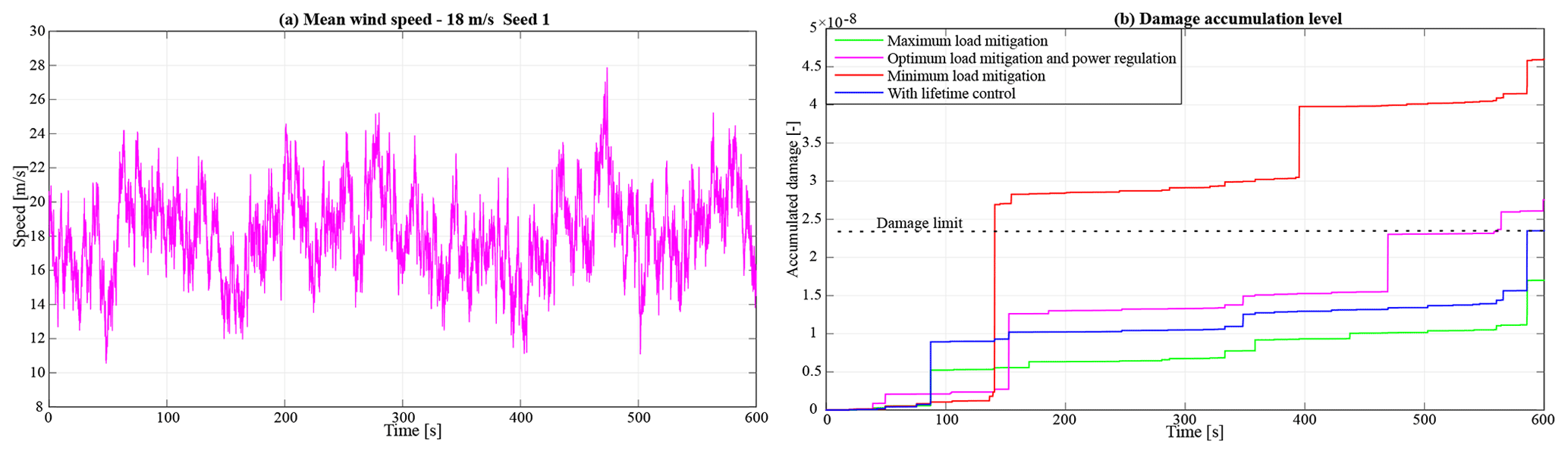
The performance of the lifetime control scheme in different blade load mitigation scenarios is shown in Fig. 6b. As shown, the adaptive lifetime control strategy controls the damage accumulation in the blades to reach the predefined damage limit at the desired lifetime of 600 s. While the control strategy with maximum load mitigation achieves the same desired result, the lifetime control scheme spreads the incremental damage accumulation over the entire operation window by dynamically switching between the different load mitigation levels.
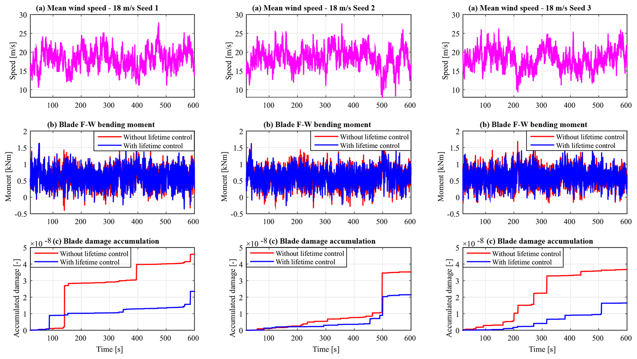
The baseline controller (without lifetime control) used for comparisons is RDAC combined with aIPC without lifetime control, whereby switching in aIPC is only based on incoming wind speed. To evaluate the proposed controller in varying wind fields, six profiles with mean wind speeds of 18 and 14 m s−1, each having three seeds, are used. The three wind profiles having a mean wind speed of 18 m s−1 are shown in Fig. 7a. A comparison in blade F–W bending moment load mitigation performance is shown in Fig. 7b. On average (for the three wind fields), an adaptive lifetime controller achieves a 9.39 % reduction in standard deviation compared with the baseline controller. Additionally, there is significant reduction in the accumulated damage as shown in Fig. 7c.
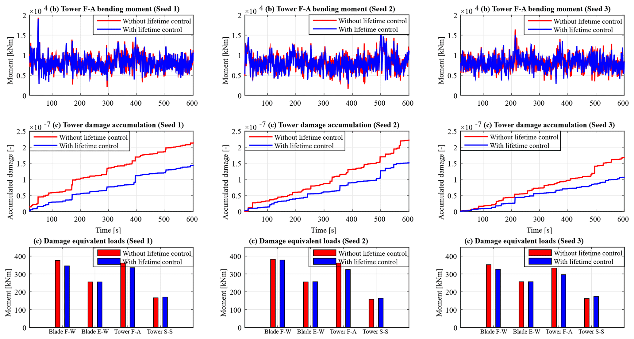
The performance of the adaptive lifetime control strategy in mitigating tower loads is also evaluated. As illustrated in Fig. 8a, a significant reduction in tower F–A oscillation is observed, with the average standard deviation reducing by 6.58 %. A reduction in tower damage accumulation can be seen in Fig. 8b. This shows that the lifetime control of blades, which reduces 1P fatigue loads, leads to reduced damage accumulation in the tower due to 3P fatigue loads. To evaluate the performance of the proposed lifetime control scheme in load mitigation in different tower and blade load channels, damage equivalent load (DEL) analysis is carried out using MLife software (Hayman, 2012). Based on fatigue analysis carried out with results obtained using the 10 min stochastic wind profile shown in Fig. 7a, the lifetime controller reduces DELs in the blade F–W and tower F–A as illustrated in Fig. 8c. No noticeable change in blade E–W DEL is achieved. However, a slight increase is seen in tower S–S DEL, which is attributed to a slight increase in pitch activity for improved load reduction.
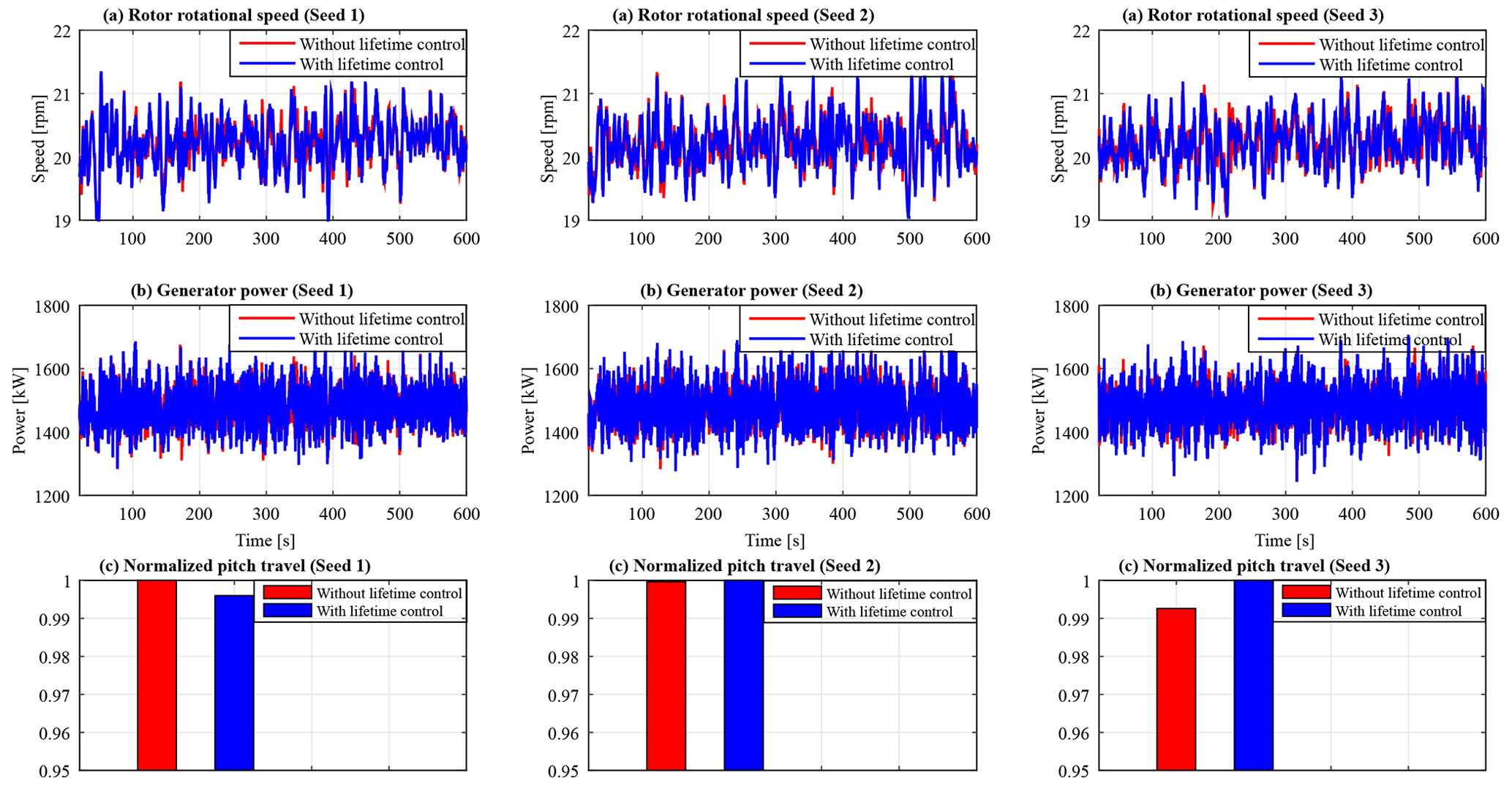
Despite the adaptive lifetime controller achieving improved performance in reducing damage accumulation in both rotor blade and tower, it is important to ascertain that this does not compromise the speed and power regulation performance. To illustrate this, the rotor speed and generator power are evaluated as shown in Fig. 9. With lifetime control, no notable change is realized with respect to rotor speed regulation. Although a slight increase of 8.7 % in power standard deviation is noted, the generated power fluctuates within acceptable limits. The mean power is identical at 1560.13 and 1559.97 kW for the baseline and lifetime controllers, respectively. Improvement in both load mitigation and rotor speed regulation is achieved with insignificant additional pitch activity as illustrated in Fig. 9c. The average total pitch travel marginally increases by 0.13 %.
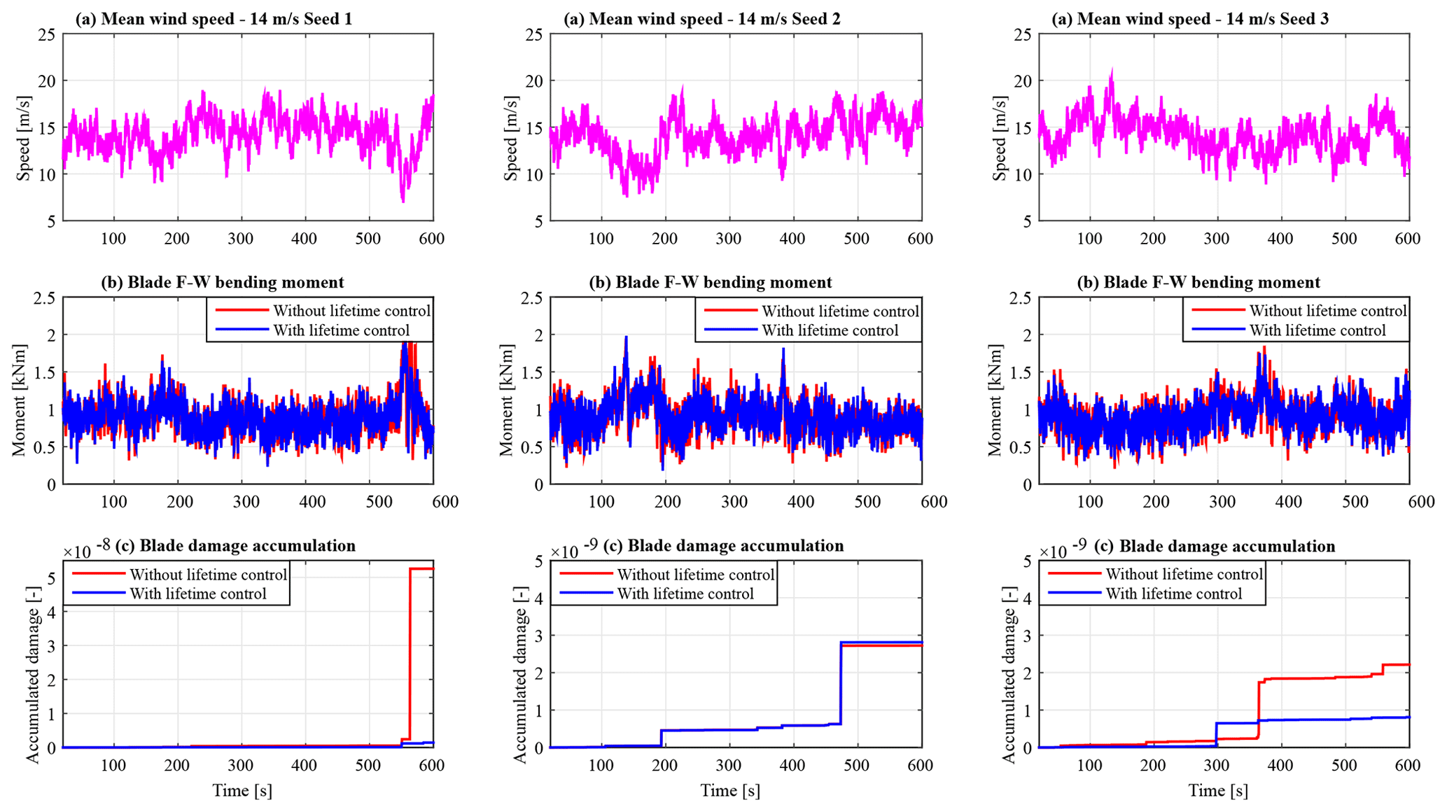
Given that an 18 m s−1 wind field realization has a low occurrence probability since wind turbines spend most of the time operating in near-rated wind conditions, the proposed adaptive lifetime control strategy is evaluated using a near-rated wind profile. For this, three IEC type C stochastic wind field realizations shown in Fig. 10a, each with a mean speed of 14 m s−1 and a turbulence intensity of 12 % at 15 m s−1, are used. Fatigue load mitigation performance of the proposed lifetime controller in the blades is evaluated against the baseline controller as illustrated in Fig. 10b. The lifetime controller achieves a 10.1 % reduction in standard deviation in blade F–W bending moment. Additionally, significant reduction in the accumulated damage is achieved.
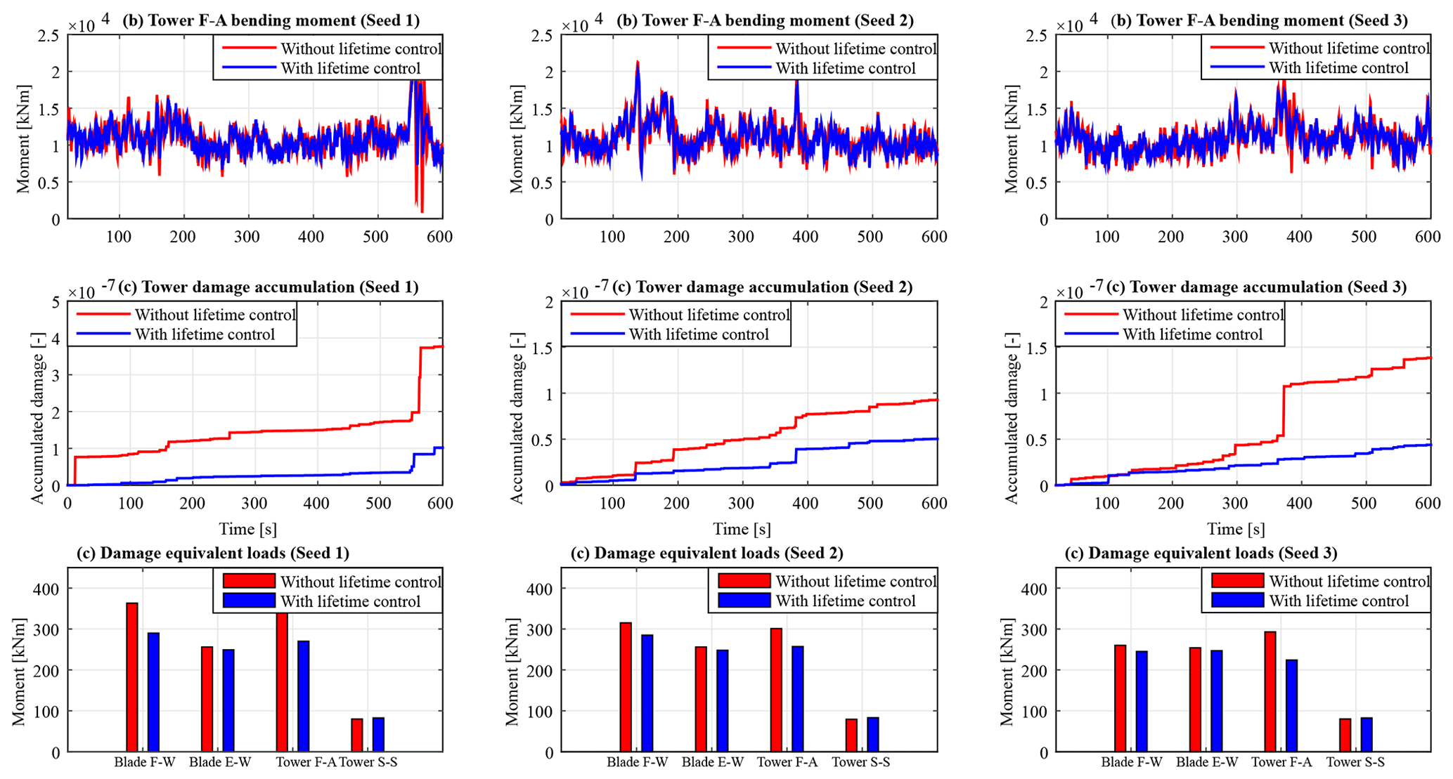
A reduction in tower fore–aft loading and damage accumulation is realized as shown in Fig. 11a. The standard deviation in tower loading is reduced by 11.2 %. Fatigue analysis is carried out using simulation results based on the wind profiles shown in Fig. 10a. As illustrated in Fig. 11c, the adaptive lifetime controller achieves DEL reduction in all load channels except the slight increase in tower S–S DEL.
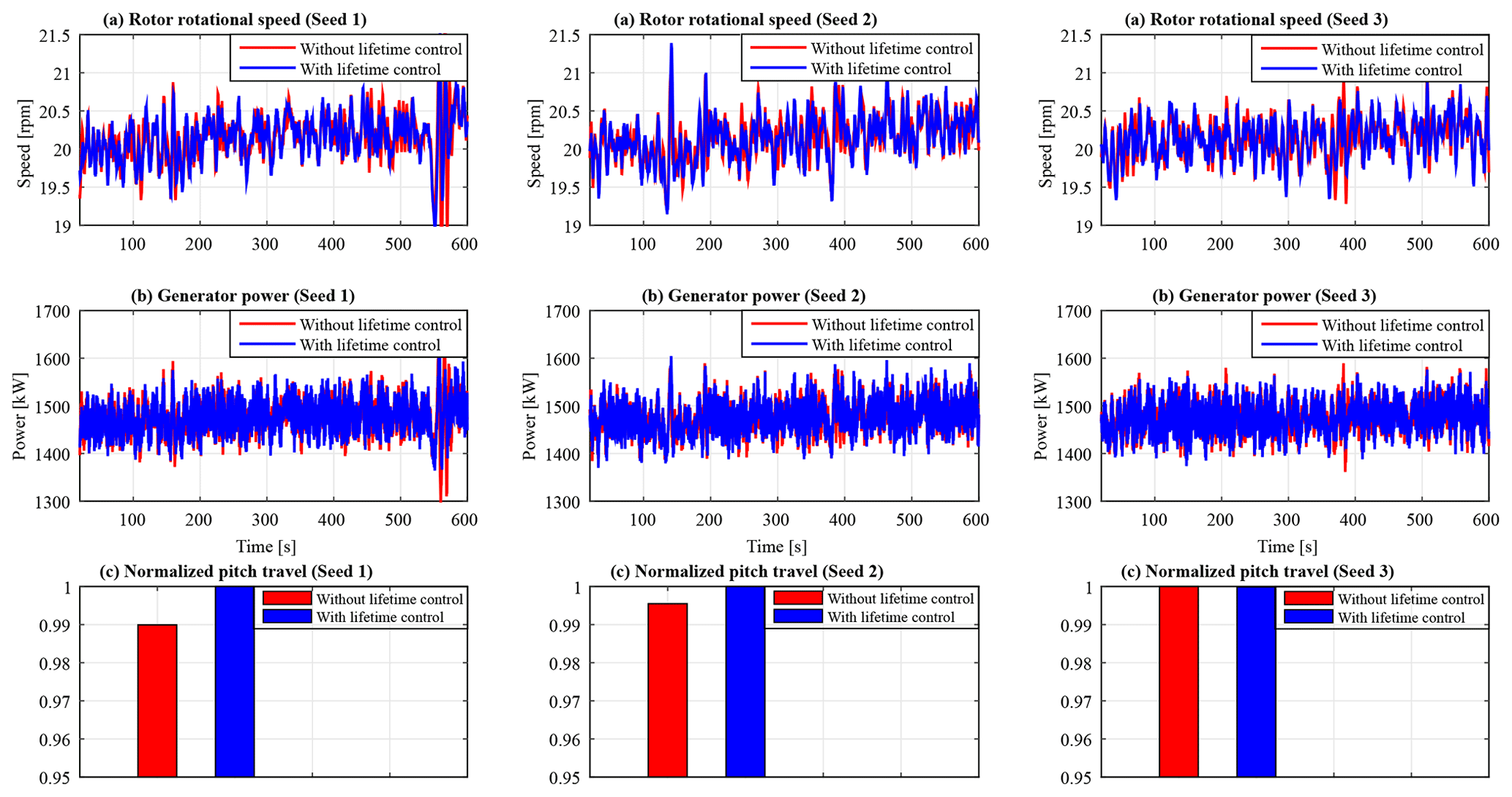
Speed and power regulation performance of the proposed controller is also evaluated at near-rated wind conditions as shown in Fig. 12. With lifetime control, improvement is realized in both speed and power regulation, with the standard deviation in rotor speed and generated power reducing by 1.3 % and 1.2 %, respectively. The mean power is identical at 1553.5 and 1553.73 kW for the baseline and lifetime controllers, respectively. Improvement in both load mitigation and speed regulation comes with insignificant additional pitch activity as illustrated in Fig. 12c. The average total pitch travel increases slightly by 0.5 %. Therefore, the proposed adaptive lifetime control strategy performs well in near-rated wind conditions.
In this paper, a prognostics-based adaptive control strategy for lifetime control of wind turbines is presented. A robust disturbance accommodating controller (RDAC) designed using mixed sensitivity H∞ control is used as the primary controller for mitigating tower loads and regulating rotor speed using a CPC signal. On the other hand, an aIPC controller designed using the LQG control method is used as a lifetime controller. The gains of each of its five IPC controllers are adapted based on the state of health of the rotor blades obtained using an online damage evaluation model to strike a compromise between lifetime control through load mitigation and speed regulation.
Through simulation using a 1.5 MW wind turbine model, it is demonstrated that the adaptive lifetime control strategy controls the damage accumulation in the blades to guarantee a given damage limit at the desired lifetime. A reduction in accumulated damage in the tower is also realized. This can potentially be used for optimizing maintenance scheduling in wind farms by synchronizing aging of wind turbine components, hence reducing operation and maintenance costs and increasing operational reliability. Fatigue analysis indicates a reduction in DELs in most load channels. This improvement is realized without compromise in the speed and power regulation performance. The lifetime controller achieves these results without significant increase in pitch actuator duty cycle. In the future, adaptive lifetime control based on nonlinear damage accumulation models will be considered. Additionally, the use of new concepts for state-of-health indicators such as a change in modal parameters for structural health monitoring will be explored.
The code is not publicly available and cannot be shared.
Simulation data were obtained using Fatigue Aerodynamics Structures and Turbulence version 7 (FAST v7), a free wind turbine simulation tool developed by National Renewable Energy Laboratory (NREL). For additional information see the FAST user guide (https://www.nrel.gov/wind/nwtc/fastv7.html, National Renewable Energy Laboratory, 2023).
DS and JGN proposed the original idea of combining an online damage evaluation model with a switching IPC load mitigation control scheme for the lifetime extension of wind turbine blades. MHD and DS extended the work of JGN by developing an adaptive lifetime controller (RDAC) to control life consumption in the tower. Based on these ideas and with supervision from DS, EK developed an adaptive lifetime controller (aIPC), which is adaptive to wind speed changes and in which the gains of each IPC controller are adapted to dynamically control the damage accumulation of rotor blades while monitoring the life consumption of the tower. EK evaluated the prognostics scheme (RDAC+aIPC) on a 1.5 MW RWT by running simulations and analyzing obtained results. With valuable input from DS, EK wrote the manuscript. All authors contributed to this work from concept to manuscript stage.
The contact author has declared that none of the authors has any competing interests.
Publisher’s note: Copernicus Publications remains neutral with regard to jurisdictional claims in published maps and institutional affiliations.
This work is partly supported through a scholarship awarded to Edwin Kipchirchir by the German Academic Exchange Service (DAAD) in cooperation with the Ministry of Education of Kenya for his PhD study at the Chair of Dynamics and Control, UDE, Germany. We also thank Paul Fleming and the three anonymous reviewers who helped to improve the manuscript.
This paper was edited by Paul Fleming and reviewed by three anonymous referees.
Acho, L., Rodellar, J., Tutivén, C., and Vidal, Y.: Passive fault tolerant control strategy in controlled wind turbines, in: 2016 3rd Conference on Control and Fault-Tolerant Systems (SysTol), IEEE, Barcelona, Spain, 7–9 September 2016, 636–641, https://doi.org/10.1109/SYSTOL.2016.7739820, 2016. a
Apkarian, P. and Noll, D.: Nonsmooth H∞ synthesis, IEEE T. Automat. Contr., 51, 71–86, https://doi.org/10.1109/TAC.2005.860290, 2006. a
Apkarian, P. and Noll, D.: The H∞ control problem is solved, Aerospace Lab, 13, 1–11, https://doi.org/10.12762/2017.AL13-01, 2017. a
Azizi, A., Nourisola, H., and Shoja-Majidabad, S.: Fault tolerant control of wind turbines with an adaptive output feedback sliding mode controller, Renew. Energ., 135, 55–65, https://doi.org/10.1016/j.renene.2018.11.106, 2019. a
Bajrić, A., Jan, H., and Rüdinger, F.: Evaluation of damping estimates by automated operational modal analysis for offshore wind turbine tower vibrations, Renew. Energ., 116, 153–163, https://doi.org/10.1016/j.renene.2017.03.043, 2018. a
Beganovic, N., Njiri, J. G., Rothe, S., and Söffker, D.: Application of Diagnosis and Prognosis to Wind Turbine System Based on Fatigue Load, in: 2015 IEEE Conference on Prognostics and Health Management (PHM), IEEE, Austin, Texas, 22–25 June 2015, 1–6, https://doi.org/10.1109/ICPHM.2015.7245031, 2015. a, b
Beganovic, N., Njiri, J. G., and Söffker, D.: Reduction of structural loads in wind turbines based on adapted control strategy concerning online fatigue damage evaluation models, Energies, 11, 3429, https://doi.org/10.3390/en11123429, 2018. a, b
Bir, G. S.: User's guide to MBC3: Multi-blade coordinate transformation code for 3-bladed wind turbine, Tech. rep., National Renewable Energy Laboratory (NREL), https://www.nrel.gov/docs/fy10osti/44327.pdf (last access: 19 April 2023), 2010. a
Do, M. H. and Söffker, D.: Wind turbine lifetime control using structural health monitoring and prognosis, IFAC-PapersOnLine, 53, 12669–12674, https://doi.org/10.1016/j.ifacol.2020.12.1847, 2020. a, b, c
Do, M. H. and Söffker, D.: Wind turbine robust disturbance accommodating control using non-smooth H∞ optimization, Wind Energy, 25, 107–124, https://doi.org/10.1002/we.2663, 2022. a, b, c, d
Dong, X., Lian, J., Wang, H., Yu, T., and Zhao, Y.: Structural vibration monitoring and operational modal analysis of offshore wind turbine structure, Ocean Eng., 150, 280–297, https://doi.org/10.1016/j.oceaneng.2017.12.052, 2018. a
El Maati, Y. A. and El Bahir, L.: Optimal fault tolerant control of large-scale wind turbines in the case of the pitch actuator partial faults, Complexity, 2020, 1–17, https://doi.org/10.1155/2020/6210407, 2020. a
Gao, Z. and Liu, X.: An overview on fault diagnosis, prognosis and resilient control for wind turbine systems, Processes, 9, 300, https://doi.org/10.3390/pr9020300, 2021. a
Hayman, G.: MLife theory manual for version 1.00, Tech. rep., National Renewable Energy Laboratory (NREL), Golden, Colorado, https://www.nrel.gov/wind/nwtc/assets/pdfs/mlife-theory.pdf (last access: 19 April 2023), 2012. a
Jain, T. and Yamé, J.: Health-aware fault-tolerant receding horizon control of wind turbines, Control Eng. Pract., 95, 104236, https://doi.org/10.1016/j.conengprac.2019.104236, 2020. a
Jonkman, B. J. and Kilcher, L.: TurbSim user's guide: version 1.06.00, Tech. rep., National Renewable Energy Laboratory (NREL), Golden, Colorado, USA, https://www.nrel.gov/wind/nwtc/assets/pdfs/turbsim.pdf (last access: 19 April 2023), 2012. a
Jonkman, J. M. and Buhl Jr., M. L.: FAST user's guide, Tech. Rep. NREL/EL-500-29798, National Renewable Energy Laboratory (NREL), Golden, Colorado, USA, https://www.nrel.gov/docs/fy06osti/38230.pdf (last access: 19 April 2023), 2005. a
Kim, H.-C., Kim, M.-H., and Choe, D.-E.: Structural health monitoring of towers and blades for floating offshore wind turbines using operational modal analysis and modal properties with numerical-sensor signals, Ocean Eng., 188, 106226, https://doi.org/10.1016/j.oceaneng.2019.106226, 2019. a
Matsuishi, M. and Endo, T.: Fatigue of metals subjected to varying stress, Japan Society of Mechanical Engineers, 68, 37–40, 1968. a
Miner, M. A.: Cumulative damage in fatigue, J. Appl. Mech., 12, A159–A164, https://doi.org/10.1115/1.4009458, 1945. a
Musallam, M. and Johnson, C. M.: An efficient implementation of the rainflow counting algorithm for life consumption estimation, IEEE T. Reliab., 61, 978–986, https://doi.org/10.1109/TR.2012.2221040, 2012. a, b, c, d, e
National Renewable Energy Laboratory (NREL): FAST v7, https://www.nrel.gov/wind/nwtc/fastv7.html, last access: 19 April 2023. a
Njiri, J. G., Beganovic, N., Do, M. H., and Söffker, D.: Consideration of lifetime and fatigue load in wind turbine control, Renew. Energ., 131, 818–828, https://doi.org/10.1016/j.renene.2018.07.109, 2019. a, b
Pegalajar-Jurado, A. and Bredmose, H.: Reproduction of slow-drift motions of a floating wind turbine using second-order hydrodynamics and operational modal analysis, Mar. Struct., 66, 178–196, https://doi.org/10.1016/j.marstruc.2019.02.008, 2019. a
Ragan, P. and Manuel, L.: Comparing estimates of wind turbine fatigue loads using time-domain and spectral methods, Wind Eng., 31, 83–99, https://doi.org/10.1260/030952407781494494, 2007. a, b
Rinker, J. and Dykes, K.: WindPACT reference wind turbines, Tech. rep., National Renewable Energy Laboratory (NREL), Golden, Colorado, USA, https://www.nrel.gov/docs/fy18osti/67667.pdf (last access: 19 April 2023), 2018. a
Wright, A. D.: Modern control design for flexible wind turbines, University of Colorado at Boulder, Golden, Colorado, USA, https://www.proquest.com/openview/f8f93112e807853ee3cbc16d4c8a64e7/1?pq-origsite=gscholar&cbl=18750&diss=y (last access: 19 April 2023), 2003. a
Wright, A. D. and Fingersh, L. J.: Advanced control design for wind turbines part I: Control design, implementation, and initial tests, Tech. Rep. NREL/TP-500-42437, National Renewable Energy Laboratory (NREL), Golden, Colorado, USA, https://www.osti.gov/biblio/927269 (last access: 19 April 2023), 2008. a
Yuan, R., Li, H., Huang, H. Z., Zhu, S. P., and Gao, H.: A nonlinear fatigue damage accumulation model considering strength degradation and its applications to fatigue reliability analysis, Int. J. Damage Mech., 24, 646–662, https://doi.org/10.1177/1056789514544228, 2015. a
Ziegler, L., Gonzalez, E., Rubert, T., Smolka, U., and Melero, J. J.: Lifetime extension of onshore wind turbines: A review covering Germany, Spain, Denmark, and the UK, Renewable and Sustainable Energy Reviews, 82, 1261–1271, https://doi.org/10.1016/j.rser.2017.09.100, 2018. a
- Abstract
- Introduction
- Wind turbine health monitoring
- Control strategy for load mitigation and speed regulation
- Control of wind turbine lifetime: an illustrative example using the 1.5 MW NREL reference wind turbine
- Results and discussion
- Summary and conclusion
- Code availability
- Data availability
- Author contributions
- Competing interests
- Disclaimer
- Acknowledgements
- Review statement
- References