the Creative Commons Attribution 4.0 License.
the Creative Commons Attribution 4.0 License.
Periodic dynamic induction control of wind farms: proving the potential in simulations and wind tunnel experiments
Joeri Alexis Frederik
Robin Weber
Stefano Cacciola
Filippo Campagnolo
Alessandro Croce
Carlo Bottasso
Jan-Willem van Wingerden
As wind turbines in a wind farm interact with each other, a control problem arises that has been extensively studied in the literature: how can we optimize the power production of a wind farm as a whole? A traditional approach to this problem is called induction control, in which the power capture of an upstream turbine is lowered for the benefit of downstream machines. In recent simulation studies, an alternative approach, where the induction factor is varied over time, has shown promising results. In this paper, the potential of this dynamic induction control (DIC) approach is further investigated. Only periodic variations, where the input is a sinusoid, are studied. A proof of concept for this periodic DIC approach will be given by the execution of scaled wind tunnel experiments, showing for the first time that this approach can yield power gains in real-world wind farms. Furthermore, the effects on the damage equivalent loads (DEL) of the turbine are evaluated in a simulation environment. These indicate that the increase in DEL on the excited turbine is limited.
- Article
(3578 KB) - Full-text XML
- BibTeX
- EndNote
The interaction between wind turbines in a wind farm through their wake is a field of research as old as wind farms themselves. The wake of a turbine has a wind field with a lower velocity and a higher turbulence intensity (TI), resulting in a lower power production and higher relative loads for downstream turbines. To exploit this interaction between turbines, induction control (sometimes called “derating”), with induction defined as the in-wake speed deficit, has been a popular research topic in recent years. The concept of this control approach is schematically shown in Fig. 1. Despite initial promising results (Marden et al., 2013; Gebraad et al., 2013), recent studies indicate that the power gain that can be achieved with steady-state induction control is limited to non-existing (Campagnolo et al., 2016a; Nilsson et al., 2015; Annoni et al., 2016).
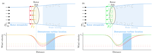
Figure 1A schematic representation of a wind turbine in a flow field, showing the working principles of static (a) and dynamic induction control (b). At the top, the turbine is simplified as a rotor disk, and its streamtube – the area where the wind speed is affected by the turbine settings – is depicted. The force FT exerted on the wind is shown for different induction settings a, where red depicts “greedy” settings that result in optimal single-turbine power capture (). The orange (a≈0.3) and yellow (a≈0.25) lines depict arbitrary static derating settings that can be achieved by changing either the generator torque or the collective pitch angles of the turbine. The green lines represent periodic DIC. The bottom figures show the corresponding wind velocity profiles, with respect to inflow velocity U∞, as a function of the distance from the turbine. The area highlighted in blue is where a downstream turbine is typically located.
An alternative approach, first mentioned in Westergaard (2013), is to actively manipulate wake recovery. Recent simulation studies (Goit and Meyers, 2015; Munters and Meyers, 2017) have shown that so-called dynamic induction control (DIC) improves the power production in small to medium-sized wind farms. This approach, where the induction factor is varied over time, generates a turbulent wind flow that enables enhanced wake recovery. Consequently, downstream turbines will compensate for the power loss of the upstream turbine, leading to a higher overall power production of the wind farm. In Munters and Meyers (2017), the optimal dynamic control inputs are found using a computationally expensive adjoint-based model predictive control (MPC) approach. The thrust coefficient of each turbine is used as the control input. This input is only constrained by different wind turbine response times τ and maximum allowable thrust coefficient settings , resulting in non-smooth control signals.
In Munters and Meyers (2018), a simpler approach is suggested: the induction variation is limited to a sinusoidal signal implemented on an actuator disk. This approach is here dubbed “periodic DIC”. A grid search with different amplitudes and frequencies is performed to find the periodic dynamic signal that results in the maximum energy extraction in a high-fidelity simulation environment. The effect of this approach on the streamtube and downstream wind velocity is shown in Fig. 1. It should be noted that the applied excitation has a very low frequency.
However, no experiments have yet been executed that validate this approach on actual wind turbines, either scaled or full-sized. Furthermore, the effects of DIC on the loads of the turbines are yet to be evaluated. This paper aims to bridge this knowledge gap by executing a thorough evaluation of DIC both in simulation environments and in wind tunnel experiments. The effects of DIC on the loads on a turbine level are evaluated using the aeroelastic tool Cp-Lambda (Bottasso and Croce, 2009–2018; Bottasso et al., 2006). For the wind tunnel experiments, the atmospheric boundary layer (ABL) wind tunnel of the Politecnico di Milano (Polimi) is used (Bottasso et al., 2014). Three G1 models, which have a rotor diameter of 1.1 m and are developed by the Technical University of Munich (TUM) (Campagnolo et al., 2016a, b, c), will be used as turbine models.
To verify the validity of the periodic dynamic induction approach for fast wake recovery in a wind farm, a number of wind tunnel experiments in both low and high-TI conditions are executed. All experiments are executed at a below-rated wind speed, i.e., in operating region II. The effect of varying the amplitude and frequency of the signals is studied, and the performance of this approach is compared with state-of-the-art wind farm power maximization control strategies. As comparison cases, static induction control and wake redirection control (Fleming et al., 2014), where upstream turbines are yawed with respect to the wind direction to redirect the wake away from downstream machines, are implemented in the wind tunnel. A positive result in these experiments would be an important step towards proving the validity of this approach in real wind farms.
The structure of this paper will be as follows: in Sect. 2, the DIC strategy will be explained. Sections 3 and 4 will elaborate on the simulation environment and the experimental setup, respectively. In Sect. 5, the simulation results will be presented, followed by the experimental results obtained in the wind tunnel in Sect. 6. Finally, the conclusions will be drawn in Sect. 7.
In this section, the strategy behind dynamic induction control will be discussed briefly. As mentioned in the introduction, the approach presented in Munters and Meyers (2018) is used as a basis for this paper: the thrust force of the upstream wind turbine is excited to induce wake mixing, in order for downstream turbines to increase their power capture. It is shown that the amplitude and frequency of a sinusoid determine the overall power production. The optimum found in here is a Strouhal number of St=0.25, with an amplitude of the disk-based thrust coefficient . The Strouhal number is defined as for a given frequency f, rotor diameter D and inflow velocity U∞, while , with a being the axial induction factor (Goit and Meyers, 2015). This disk-based thrust coefficient relates to the thrust coefficient CT as . For the G1 models and an inflow velocity of 5.65 m s−1, this Strouhal number would result in an excitation frequency of approximately 1.3 Hz.
However, there are some fundamental differences between Munters and Meyers (2018). First of all, due to the size of the wind tunnel (see Sect. 4), a three-turbine wind farm is the deepest possible array configuration. The amplitude and frequency ranges were slightly reduced due to limits on the available time in the wind tunnel. Furthermore, the number of experiments executed in this paper is slightly lower. The amplitudes and frequencies for the wind tunnel experiments are chosen such that sufficient data points can be investigated around the optimum found in Munters and Meyers (2018). For the aeroelastic simulations, three different frequency points are evaluated to demonstrate the effect on the turbine loads. Finally, a method should be found to vary the thrust coefficient of a real (scaled) wind turbine. The thrust coefficient can be manipulated by varying either the collective pitch angle or the generator torque of the turbine. Of these two, the former approach is the most straightforward and easy to implement. Therefore, the collective pitch angle β of the upstream model was excited periodically. This results in a slightly different thrust signal, as shown in Fig. 2, but simulations show that the difference in output for these input signals is limited. All these differences are summarized in Table 1
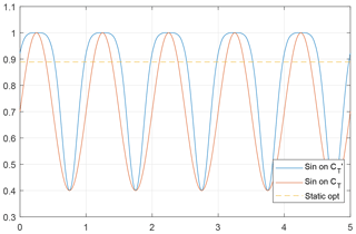
Figure 2Values of CT for different types of input signals, created using a lookup table of the G1 turbine model. The thrust coefficient is shown for three different sinusoidal excitations: on CT, on and on the collective pitch angle β, tuned such that the amplitude of is 1.5. The dashed line shows the steady-state optimal CT.
Table 1Differences between the approach in Munters and Meyers (2018) and both the simulations and wind tunnel experiments presented in this paper. The number of experiments executed here is slightly lower. As a result, choices are made with regards to the excitation amplitudes and frequencies that have been investigated.

n/a = not applicable.
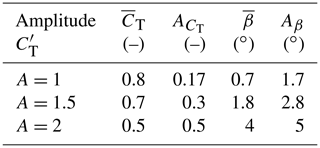
For the tests performed within the research described in this paper, the standard power controller was augmented in order to enable the rotor thrust coefficients to follow a specific sine wave function. However, there is no unique way of achieving this goal, since a specific thrust coefficient CT(λ, β) can be obtained by operating at different combinations of tip speed ratio λ and blade pitch β. In turn, the tip speed ratio can be varied either by changing the reference followed by the generator torque or changing the blade pitch. In this paper, a strategy that only changes the blade collective pitch is adopted. The implementation of this strategy simply requires changing the collective fine pitch at which the model blades are set when the machine operates in partial load conditions (region II). The fine pitch was tuned experimentally, by means of a trial and error procedure conducted with a stand-alone model, to achieve the desired mean and amplitude A as reported in Table 2. The effects of these control actions in terms of impacts on the power output of the three-turbine wind farm will be discussed in Sect. 6.
Table 2Average and amplitude of the three different thrust coefficient oscillations whose results are discussed in Sect. 6, as well as the mean pitch angle average and amplitude Aβ used to achieve these signals. Note that, as explained in Sect. 2, these collective pitch settings are not identical for different frequencies. Instead, they are tuned such that the mean and amplitude of CT as given below are followed as accurately as possible.
Finally, the performance of periodic DIC as a wind farm power maximization strategy will be evaluated. To achieve this, a comparison will be made with wind farm power maximization approaches that have already been investigated more extensively in the literature:
-
Greedy control: all turbines operate at their individual optimum, disregarding wake interaction between turbines. This means that all turbine have an induction factor of (or a thrust coefficient of or ) and a yaw angle of 0∘ with respect to the wind direction.
-
Static induction control (also called derating control): the induction settings of upstream turbines are manipulated such that the wind farm power capture can be maximized. In this paper, the induction factor is controlled by means of the collective pitch angles of the (upstream) turbines, although using the generator torque is also an option. This strategy has been a popular research topic in recent years and has shown both promising (Marden et al., 2013; Gebraad et al., 2013) and inconclusive (Campagnolo et al., 2016a; Nilsson et al., 2015; Annoni et al., 2016) results.
-
Yaw control (also called wake redirection control): upstream turbines are yawed with respect to the wind direction such that the wake is steered away from downstream machines. For this approach, the control inputs are the yaw angles of the (upstream) turbines with respect to the wind. Yaw control has been demonstrated to effectively increase the wind farm power capture in wind tunnel experiments (Campagnolo et al., 2016c) and full-scale experiments (Fleming et al., 2017; Howland et al., 2019).
The control inputs that lead to the highest power capture are found using the static FLORIS model (Annoni et al., 2018; Doekemeijer and Storm, 2018). This parametric model is calibrated with wind tunnel measurements, as described in Schreiber et al. (2017). The control settings are then implemented on the same wind farm setup in the wind tunnel such that a fair comparison can be made. In Sect. 6, the results of these experiments will be evaluated.
In order to evaluate the effect of DIC on turbine level, the aeroelastic tool Cp-Lambda (Code for Performance, Loads, Aeroelasticity by Multi-Body Dynamics Analysis) (Bottasso and Croce, 2009–2018; Bottasso et al., 2006) has been used. This software is an aeroelastic code based on finite-element multibody formulation, which implements a geometrically exact nonlinear beam formulation (Bauchau, 2011) to model flexible elements such as blade, tower, shaft and drive train. The generator drive train model can include speed-dependent mechanical losses. The rotor aerodynamics are modeled via blade element momentum (BEM) theory or a dynamic inflow model and may consider corrections related to hub and tip losses, tower shadow, unsteadiness, and dynamic stall, whereas lifting lines can be attached to both tower and nacelle to model the related aerodynamic loads.
For the fatigue analysis, the model of the NREL 5 MW reference wind turbine (Jonkman et al., 2009) was considered. This reference 5 MW wind turbine, with a 126 m rotor diameter and a rated wind speed of 11.4 m s−1, is a well-known model, widely analyzed in the literature and able to represent modern and already working wind turbines. Each blade is discretized with 30 cubic finite elements and the tower with 20 cubic elements. Additionally, pitch and torque actuators are modeled, respectively, as second- and first-order systems and the model is completed by a standard proportional-integral-derivative (PID) controller (Jonkman et al., 2009). Finally, 10 min wind time histories of turbulence class “A”, according to Design Load Case (DLC) 1.1 of IEC 61400-1 Ed.3. (2004), generated by the software TurbSim (Jonkman and Buhl, 2006), were given as input to the aeroelastic solver.
The experimental results presented in this paper were gathered by performing dedicated tests within the wind tunnel of the Polimi, which is a closed-return configuration facility arranged in a vertical layout and equipped with two test rooms. A detailed description of the facility can be found in Bottasso et al. (2014). The tests were performed within the boundary layer test section, which has been conceived for civil, environmental and wind energy applications. This section has a large cross-sectional area of 13.84×3.84 m, which allows for low blockage effects even with several relatively large turbine models installed within the test section.
Roughness elements located on the floor and turbulence generators placed at the chamber inlet are commonly used to mimic the atmospheric boundary layer to scale in terms of vertical shear and turbulence spectrum. During the experiments described later on, two boundary layer configurations were used: one generating low turbulent (low-TI) and one generating highly turbulent (high-TI) flow conditions. These conditions roughly correspond to off- and onshore operation, respectively. The flow characteristics are shown in Fig. 3 together with the extension of the model's rotor disk along the vertical axis. The coefficients of the vertical-shear exponential law, shown in the same picture, that best fit the experimental data are 0.144 and 0.214 for the low-TI and high-TI cases, respectively.
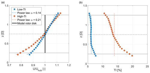
Figure 3Vertical wind speed profile (a) and turbulence intensity (b) as a function of height above the tunnel floor, for low (low-TI) and high (high-TI) turbulence experiments.
4.1 Wind turbine models
Three G1 wind turbine models developed at TUM were used to perform the experiments reported in this paper. This model type was widely employed and described in detail in previous research (Campagnolo et al., 2016a, b, c) and is shown within the boundary layer test section of the Polimi wind tunnel in Fig. 4. The setup of the turbines in the tunnel is shown in Fig. 5.
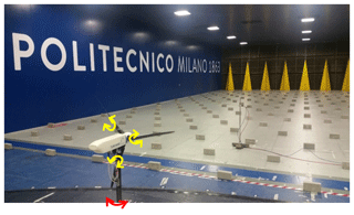
Figure 4A G1 scaled wind turbine model within the wind tunnel of the Politecnico di Milano. The yellow and red arrows show the pitch and yaw control possibilities, respectively. The yellow spires and bricks in front of the model create the high-TI flow conditions.
With a rotor diameter of D=1.1 m and a rated rotor speed of 850 rpm, the model was designed to have a realistic energy conversion process and wake behavior: it exhibits a power coefficient CP≈0.41 and a thrust coefficient CT≈0.81 for a tip speed ratio λ≈8.2 and a blade pitch β≈0.4∘.
The turbine is actively controlled with individual pitch, torque and yaw actuators and features comprehensive on-board sensorization. Three individual pitch actuators and connected positioning controllers allow for an overall accuracy of the pitch system of 0.1∘ for each blade and the ability to oscillate the blade pitch with an amplitude of 5∘ at 15 Hz around any desired pitch angle. Strain gauges are installed on the shaft to measure bending and aerodynamic torsional loads, as well as at the tower foot to measure fore–aft and side–side bending moments. A pitot tube, placed three rotor diameters upstream of the first turbine model, provides measurements of the undisturbed wind speed at hub height. Finally, air pressure, temperature and humidity transducers allow for measurements of the air density within the test section. The measurements of these sensors are used to determine the performance of the turbine models. The thrust coefficient is obtained using measurements of the pitot tube wind speed measurement and fore–aft bending moment, while correcting for the effects of the tower and nacelle drag.
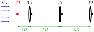
Figure 5A schematic top view of the wind farm setup in the wind tunnel. The pitot tube (PT), which measures the inflow velocity, is located two rotor diameters D in front of turbine 1 (T1). The spacing between the turbines is 5 D and the wind flows from left to right.
4.2 Control system
For each wind turbine model, control algorithms are implemented on a real-time modular Bachmann M1 system. Demanded values (e.g., pitch angle or yaw angle references) are then sent to the actuators, where the low-level control is performed. Torque signals, shaft bending moments and rotor azimuth position are recorded with a sampling rate of 2.5 kHz, while all other measurements are acquired with a sampling rate of 250 Hz. A standard power controller is implemented on each M1 system based on Bossanyi (2000), with two distinct control regions. Below rated wind speed, blade pitch angles are kept constant, while the generator torque reference follows a function of the rotor speed with the goal of maximizing the energy extraction. Above rated wind speed, the generator torque is kept constant and a proportional-integral (PI) controller adjusts the collective pitch of the blades in order to keep the generated power at the desired level. All experiments presented in this work are performed below rated wind speed.
To evaluate the effects of DIC on the loads of the excited turbine, a full set of aeroelastic turbulent simulations (DLC 1.1) has been executed. These analyses have been conducted on the NREL 5 MW wind turbine with the main goal of quantifying the effect of this DIC on the fatigue loads. Force and moment sensors have been placed on the main subcomponents of the wind turbine, such as tower base and tower top, blade root, hub, and drive train. The results presented in the next sections will focus on the main sensors, such as the blade root flap- and edgewise bending moments, tower base fore–aft bending, and hub torsional moments, as well as some controller data (blade pitch and rotor speed), which highlight the effects of the controllers.
DIC was assumed to be activated for wind speeds between 3 and 25 m s−1, to cover the totality of regions I-1∕2, II, II-1∕2 and III. Notice that 25 m s−1 seems a rather high speed, considering the fact that so far, the effectiveness of DIC has only been evaluated in region II. In region III, the lower rotor inductions (i.e., a lower in-wake speed deficit) together with the high inflow velocity may guarantee the full power region for the downwind rotor(s). Nevertheless, in the 10 min simulation, the high turbulence intensity (class A) causes a relatively long period where the mean wind speed is below the rated one and hence DIC may have an important effect on the wake. From this point of view, extending the authority of DIC up to 25 m s−1 is to be regarded as a conservative choice. For clarity, the rated wind speed of 11.4 m s−1 will be shown in the figures showing the damage equivalent loads (DELs) at different mean wind speeds.
Strouhal numbers of St=[0.3, 0.4, 0.5] and a pitch amplitude βDIC=2∘ were used in the aeroelastic simulations of the 5 MW turbine. Considering the diameter of this wind turbine model (126 m), the frequency of DIC fDIC is between Hz at 3 m s−1 (and St=0.4) and Hz at 15 m s−1 (and St=0.5), which corresponds to a period equal to between 105 and 16.8 s, respectively.
Due to the relatively low excitation frequency, the baseline turbine control is able to trim the machine without a significant additional effort or detrimental performance. Moreover, a coalescence between the DIC input frequency and turbine vibratory modes is not to be expected, at least for onshore or offshore turbines installed on rigid foundations.
Figure 6 shows an example of the time response of the machine with and without DIC. These simulations have been performed with a normal turbulence model (NTM) of class-A wind (IEC 61400-1 Ed.3., 2004) with a mean hub wind speed of 9 m s−1, generated with TurbSim (Jonkman and Buhl, 2006). In these conditions, the wind turbine baseline control switches between region II, II-1∕2 and III. The figure shows the baseline condition, i.e., the one without the DIC controller, and two simulations with Strouhal number St=0.4 and St=0.5. Figure 6a refers to the pitch activity, Fig. 6b to the rotor speed and Fig. 6c to the power. The collective pitch angle time histories show the DIC activity superimposed on the trim pitch. As can be seen, the rotor speed and power production with DIC active behave similarly to that of the baseline case (solid lines), showing that the addition of the periodic pitch motion is not detrimental in terms of trimmer performance.
Figure 7 shows the power spectral density (PSD) of the rotor speed (a) and blade root flapwise bending moment with a NTM at 15 m s−1, again for the baseline case (solid red) and for DIC with Strouhal numbers St=0.4 and St=0.5. Both figures show a new frequency corresponding to the DIC excitation. This peak is far from the other aeroelastic frequencies of the wind turbine (the first being the tower fore–aft at f=0.31 Hz) but may have an important role in the fatigue loads.
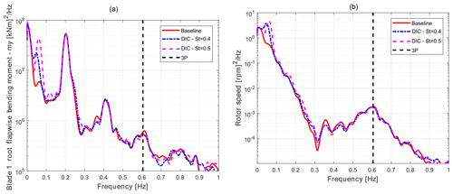
Figure 7PSD comparison of the blade root flapwise bending moment (my) (a) and the rotor speed (b) between baseline (solid red) and DIC controlled with St=0.4 (dash–dotted blue) and St=0.5 (dashed magenta) turbine for NTM class A at 15 m s−1.
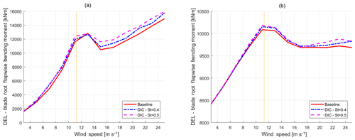
Figure 8Comparison between blade root flapwise (a) and edgewise (b) DEL of the baseline (solid red) and DIC with St=0.4 (dash–dotted blue) and St=0.5 (dashed magenta) as functions of mean wind speed. The dashed yellow line indicates the rated wind velocity. Typically, DIC will only be implemented at below-rated inflow velocities.
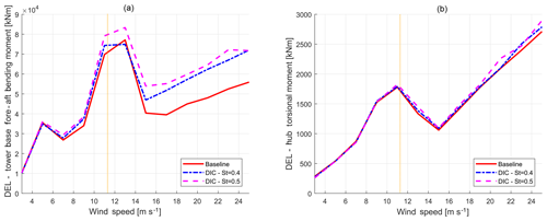
Figure 9Comparison between tower base fore–aft bending moment (a) and hub torsional moment (b) DEL of the baseline (solid red) and DIC with St=0.4 (dash–dotted blue) and St=0.5 (dashed magenta) as functions of mean wind speed. The dashed yellow line indicates the rated wind velocity. Typically, DIC will only be implemented at below-rated inflow velocities.
From the 10 min simulations computed according to DLC 1.1 of IEC 61400-1 Ed.3. (2004), the stochastic time histories of the wind turbine loads are converted into simplified DELs through a rain flow analysis and depicted in Figs. 8 and 9 as a function of the mean wind speed. These figures show that DELs computed for the baseline case are almost always lower compared to when DIC is active, as would be expected based on Fig. 7. For each mean wind speed, the DIC frequencies correspond to Strouhal numbers 0.4 and 0.5. In these figures, DIC was always active, even for high wind speed values close to the cut-out. As a result, the baseline (solid red) curves are always lower than the controlled (dash–dotted blue and dashed magenta) curves. For clarity, the rated wind speed of 11.4 m s−1 is also shown in the figures. As can be seen, the tower base fore–aft bending moment and the blade root flapwise are affected the most by this controller. As expected, the blade edgewise bending moment is only slightly affected, since the DEL in edgewise direction is mainly driven by gravity.
In order to have a more comprehensive indication of the impact of DIC on fatigue loads, one can consider the Weibull-weighted DELs, i.e., the DELs weighted throughout the probability distribution of the wind as expressed by the Weibull distribution pw(V):
where k is the shape parameter and the scale factor and Vav the average wind speed.
The Weibull-weighted DEL, DELw, is hence computed as
where VCI and VC0 are, respectively, the cut-in and cut-out wind speed.
Considering the class A, where the Weibull distribution has k=2 and Vav=10 m s−1, it is possible to compute the Weibull-weighted DELs for the previously considered loads. To this aim, as discussed before, DIC would normally be deactivated for wind speeds higher than 15 m s−1. Therefore, in the second part of region III (from 17 to 25 m s−1), the DELs would normally be equal to the baseline values. The Weibull-weighted DELs, computed as discussed in full operating region (from 3 to 25 m s−1) together with the corresponding annual energy production (AEP), are summarized in Table 3. As can be seen, the tower base load is affected the most (7 % to 11 %), while the blade flapwise root loads increase by about 2 %. A negligible impact is found in the blade edgewise (+0.4 %) and in the hub (1 % to 2 %).
Table 3Percentage increases in the Weibull-weighted DELs and AEP (from 3 to 25 m s−1) of the excited turbine compared to the baseline for different Strouhal numbers. DIC is deactivated for wind speeds higher than 15 m s−1.

It is important to stress that, so far, the analyses have not considered the probability of activation of the DIC-based wind farm control, which will depend on the specific farm layout and wind rose. From this point of view, the computed DEL increments seen before, as well as the AEP decrease, are to be considered as the worst possible case, as if DIC would always be implemented regardless of wind direction and subsequent wake interaction. It is therefore possible to assess that the impact of DIC on turbine fatigue loads for the analyzed NREL 5 MW reference machine is small compared to the possible gains.
In this section, the results of the experiments executed in the wind tunnel at Polimi, as described in Sect. 4, will be presented. The effects of periodic DIC on the power production of a three-turbine wind farm are presented for two cases, similar to onshore and offshore wind conditions. The performance of DIC will be compared with the state-of-the-art wind farm control strategies: greedy control, “static” induction control and wake redirection control.
6.1 Power production
First, the results with low turbulent wind (TI of approximately 5 %) are evaluated. For this case, three different sets of experiments have been conducted, as defined in Table 2. These sets each represent one specific amplitude of excitation of the upstream machine: an amplitude of A=1, 1.5 and 2 of , respectively. All other machines operate at their greedy optimum.
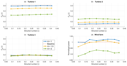
Figure 10 of the wind farm in low-TI conditions for different amplitudes A of , as defined in Table 2. Panel (d) shows the total power conversion compared to the baseline case.
Figure 10 shows the mean power of the turbines and the total wind farm. To account for the small variations in flow conditions, the power is divided by the available power in the wind. As such, these values can be seen as power coefficients. Increasing the amplitude of the sine decreases the power coefficient of turbine 1, while it increases the power coefficient of the downstream machines. However, for higher A, the loss at turbine 1 is too significant to be compensated for by the downstream turbines. The unexpectedly high power loss at turbine 1 could partly be caused by a rotor imbalance that is worsened by higher amplitudes of excitation, leading to significant vibrations of the excited machine. As a result, the case with the lowest amplitude proves to be the most effective.
The highest increase in power extraction is found with A=1 and St=0.32, resulting in a 2.4 % gain. It should be noted that this gain is mostly obtained at turbine 2, while the power at turbine 3 is only marginally higher than in the baseline case. This corresponds to the conclusions drawn in Munters and Meyers (2018), where a positive effect is observed for turbine 2, but not for machines further downstream. Table 4 gives an overview of the effect of different amplitudes and frequencies on the power production of the three-turbine model wind farm.
Table 4An overview of the total power increase with respect to the baseline case by applying dynamic induction control with different amplitudes (A, rows) and frequencies (columns) for the low-TI case. In bold are the experiments that lead to the highest power capture for each amplitude, showing an optimum around St=0.28.

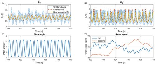
Figure 11Clockwise, the measured CT, , rotor speed and pitch angles of turbine 1 are shown during 10 s of the optimal St=0.32, A=1 DIC experiments in low TI. In (a) and (b), the unfiltered data, low-pass filtered data and a best sinusoidal fit are shown. In (d), the rotor speed during 10 s of the baseline experiment is shown for comparison.
For the sake of reproducibility, Fig. 11 shows the measurements of thrust coefficients CT and , as well as the pitch signal and rotor speed during 10 s of experiments in the optimal control settings (St=0.32, A=1). It should be noted that the thrust coefficient is obtained by using the definition
where FT is the thrust exerted on the rotor by the wind, ρ the air density, Ar the rotor area and U∞ the inflow wind velocity. FT is determined using the fore–aft bending moment, compensating for tower and nacelle drag, and the pitot measurements in front of turbine 1 (see Fig. 5) are used as data for U∞. This results in a CT signal disturbed by high-frequency noise. For this purpose, a low-pass filter with a passband frequency of 12.5 Hz was designed. This filter removes the high-frequency noise signals, while keeping the excitations caused by DIC (at f≤2.3 Hz) intact. Furthermore, a sinusoid is fitted to the measurement data using the MATLAB function lsqcurvefit. This function determines the amplitude, offset and phase of the sinusoid that best fit the data. The original data, filtered data and fitted sinusoid are all shown in Fig. 11. Finally, the pitch excitation and rotor speed are depicted, the latter clearly showing oscillations caused by DIC. However, these oscillations are relatively small compared to variations caused by changing wind conditions, as the baseline rotor speed shows.
Finally, the reliability of these results will be examined. To do this, the results are divided into four segments of 60 s. These shorter segments of measurements, still containing 15 000 measurement points and between 30 (0.5 Hz) and 138 (2.3 Hz) sine cycles, will then be used to determine the variance of the measurements.
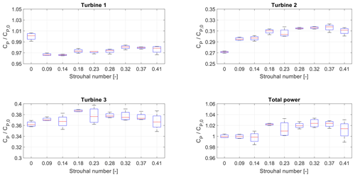
Figure 12A box plot showing the variance of the CP measurements for the low-turbulence, experiments, for all turbines individually as well as for the entire wind farm. The f=0 measurement represents the baseline case of no dynamic control.
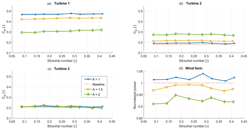
Figure 13 of the wind farm for different amplitudes A of , as defined in Table 2, in the high-TI case. Panel (d) shows the total power conversion compared to the baseline case.
Table 5An overview of the total power increase by applying dynamic induction control with different amplitudes (A, rows) and frequencies (columns) for the high-TI case. The values in bold indicate the optimal frequency at each specific amplitude of excitation.

Figure 12 shows box plots of these data sets for A=1, normalized by the steady-state optimal CP of turbine 1. This figure shows that the variance becomes larger at each downstream row due to the increased turbulence. As a result, the variance is significant in the total power production: up to ±2 % of the power. However, this figure also shows that the variance is lower than the power gained by using dynamic induction control: the lowest values of the box plot around the optimal frequency of 1.8 Hz are still higher than the baseline value. This analysis therefore indicates that the power increase is significant, as it is not a coincidental result of measurement errors.
Next, the results of the experiments with high turbulence intensity conditions (TI of approximately 10 %) will be shown. The results for all the amplitudes and frequencies that were studied are shown in Fig. 13. The main conclusion that can be drawn from this figure is that the effect of exciting the first turbine on the power production of this turbine is lower in these conditions. Due to the turbulence, the baseline power production of this turbine is already slightly lower than in low-TI conditions. As a result, the power loss at turbine 1 is negligible for the A=1 case. As the power gain at the downstream turbines is similar, the total power gain for this case is 4 %. This gain is found with A=1 and St=0.28, as can be seen in Table 5 where the results are summarized.
When the amplitude of the excitation is increased, the power loss at turbine 1 is comparable with the results in low-TI conditions. However, since the power gain at turbine 2 is slightly lower, the total power is also lower than in the baseline case. Subsequently, it seems that the amplitude of the excitation is more important than the frequency in these conditions.
6.2 Controller comparison
To emphasize the value of the results shown in the previous subsection, a comparison of the effectiveness of the periodic DIC approach with state-of-the-art wind farm control approaches is executed in the case of full wake interaction. The optimal inputs are found using the steady-state FLORIS model (Annoni et al., 2018; Doekemeijer and Storm, 2018), which is calibrated using measurements from the wind tunnel (Schreiber et al., 2017). As explained in Sect. 2, three different control strategies are implemented in the wind tunnel: greedy control, static induction control and yaw control.
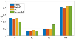
The results of these experiments are shown in Fig. 14. Similar to results in the literature (Campagnolo et al., 2016a), static induction control is found to be unable to increase the power production of this wind farm. Yaw control on the other hand results in a benefit of 3.1 % As reported earlier, DIC was able to increase the power production with 2.4 % in these conditions. It can therefore be concluded that the potential profit of periodic DIC is significantly higher than with static induction, while it is comparable to that of yaw control when full wake interaction is present.
In this paper, the effect of periodic dynamic induction control (DIC) on both individual wind turbines and small wind farms is investigated. For this purpose, both aeroelastic simulation tools and scaled wind tunnel experiments are used. The unique wind tunnel experiments with DIC show, for the first time, that this control approach not only works in a simulation environment but also in real-world experiments. The results strengthen the results found in simulations executed by Munters and Meyers (2018), showing a potential increase in power production of up to 4 %, with most of the gain coming from the first downstream turbine. Some minor differences were observed as well. First of all, the optimal Strouhal number is found to be slightly higher in the wind tunnel experiments – around St=0.3. Secondly, a smaller optimal amplitude of excitation was found. This could partly be caused by a slight rotor imbalance, which resulted in significant power losses at the excited turbine. Although higher gains were observed at turbine 2, the power loss of turbine 1 could not be compensated for at higher amplitudes of excitation.
A comparison between DIC and static induction control as well as wake redirection control shows that this approach works significantly better than the former and approximately as well as the latter. This greatly strengthens the premise that DIC is an effective method to increase the power production of a wind farm as a whole. Furthermore, by means of the aeroelastic tool Cp-Lambda, it was shown that the effect of DIC on the damage equivalent loads (DEL) of the excited wind turbine is relatively small. For the given wind turbine example, the weighted blade root edgewise DEL was in the order of 0.3 % to 0.4 % higher than in the baseline greedy control case.
In all, it can be concluded that the dynamic induction control approach shows great promise, as now both simulations and scaled experiments show that it is possible to achieve a power gain. However, some minor differences are found between simulation studies in the literature and the experiments presented here, which still need to be addressed. Future research can therefore be directed into clarifying these differences, as well as executing additional experiments, for example with different inflow velocities inside and outside the region II regime.
As the amplitude and frequency of the excitation are shown to be important control parameters, it would be a very interesting challenge to develop an algorithm that is able to optimize these parameters. Furthermore, additional analysis of the increased loads on the (downstream) turbines can be done to investigate the effect of these loads on the lifetime of turbines, as well as the trade-off between power and load effects. Another possible approach would be to investigate the effects of applying periodic DIC on intermediate wind turbines on the performance of the wind farm. Finally, application to full-scale wind turbines could be the last step in proving the validity of this approach.
The data from the wind tunnel experiments presented in this paper can be accessed here: https://doi.org/10.5281/zenodo.3673680 (Frederik et al., 2020).
The wind tunnel experiments were executed by the teams of the TU Delft (JAF, JWvW) and TUM (RW, FC, CB). The TU Delft was responsible for the control strategy development and data analysis, while TUM was responsible for the test setup, i.e., the turbine models, including the control software. The load simulations were executed by the team of Polimi (SC, AC).
The authors declare that they have no conflict of interest.
This article is part of the special issue “Wind Energy Science Conference 2019”. It is a result of the Wind Energy Science Conference 2019, Cork, Ireland, 17–20 June 2019.
This research has been supported by the Horizon 2020 (grant no. 727477 (CL-Windcon)).
This paper was edited by Katherine Dykes and reviewed by Johan Meyers and three anonymous referees.
Annoni, J., Gebraad, P. M., Scholbrock, A. K., Fleming, P. A., and v. Wingerden, J.-W. : Analysis of axial-induction-based wind plant control using an engineering and a high-order wind plant model, Wind Energy, 19, 1135–1150, 2016. a, b
Annoni, J., Fleming, P., Scholbrock, A., Roadman, J., Dana, S., Adcock, C., Porte-Agel, F., Raach, S., Haizmann, F., and Schlipf, D.: Analysis of control-oriented wake modeling tools using lidar field results, Wind Energ. Sci., 3, 819–831, https://doi.org/10.5194/wes-3-819-2018, 2018. a, b
Bauchau, O. A.: Flexible Multibody Dynamics, in: vol. 176 of Solid Mechanics and its Applications, Springer Netherlands, Dordrecht, Heidelberg, London, New York, https://doi.org/10.1007/978-94-007-0335-3, 2011. a
Bossanyi, E.: The Design of Closed Loop Controllers for Wind Turbines, Wind Energy, 3, 149–163, 2000. a
Bottasso, C. L. and Croce, A.: Cp-Lambda user manual, Tech. rep., Dipartimento di Scienze e Tecnologie Aerospaziali, Politecnico di Milano, Milano, Italy, 2009–2018. a, b
Bottasso, C. L., Croce, A., Savini, B., Sirchi, W., and Trainelli, L.: Aero-servo-elastic modeling and control of wind turbines using finite element multibody procedures, Multibody Syst. Dynam., 16, 291–308, 2006. a, b
Bottasso, C. L., Campagnolo, F., and Petrović, V.: Wind tunnel testing of scaled wind turbine models: Beyond aerodynamics, J. Wind Eng. Indust. Aerodynam., 127, 11–28, 2014. a, b
Campagnolo, F., Petrović, V., Bottasso, C. L., and Croce, A.: Wind tunnel testing of wake control strategies, in: 2016 American Control Conference (ACC), 6–8 July 2016, Boston, USA, 513–518, 2016a. a, b, c, d, e
Campagnolo, F., Petrović, V., Nanos, E., Tan, C., Bottasso, C., Paek, I., and Kim, H. K. K.: Wind tunnel testing of power maximization control strategies applied to a multi-turbine floating wind power platform, in: Proceedings of the International Offshore and Polar Engineering Conference, 26 June–1 July 2016, Rhodes, Greece, 2016b. a, b
Campagnolo, F., Petrović, V., Schreiber, J., Nanos, E. M., Croce, A., and Bottasso, C. L.: Wind tunnel testing of a closed-loop wake deflection controller for wind farm power maximization, J. Phys.: Conf. Ser., 753, 032006, https://doi.org/10.1088/1742-6596/753/3/032006, 2016c. a, b, c
Doekemeijer, B. M. and Storm, R.: FLORISSE_M, available at: https://github.com/TUDelft-DataDrivenControl/FLORISSE_M (last access: 7 August 2019), 2018. a, b
Fleming, P., Annoni, J., Shah, J. J., Wang, L., Ananthan, S., Zhang, Z., Hutchings, K., Wang, P., Chen, W., and Chen, L.: Field test of wake steering at an offshore wind farm, Wind Energ. Sci., 2, 229–239, https://doi.org/10.5194/wes-2-229-2017, 2017. a
Fleming, P. A., Gebraad, P. M., Lee, S., van Wingerden, J.-W., Johnson, K., Churchfield, M., Michalakes, J., Spalart, P., and Moriarty, P.: Evaluating techniques for redirecting turbine wakes using SOWFA, Renew. Energ., 70, 211–218, 2014. a
Frederik, J. A., Weber, R., Campagnolo, F., Bottasso, C., and van Wingerden, J. W.: Periodic dynamic induction control of wind farms: proving the potential in simulations and wind tunnel experiments – data sets, Zenodo, https://doi.org/10.5281/zenodo.3673680, 2020. a
Gebraad, P. M., van Dam, F. C., and van Wingerden, J.-W.: A model-free distributed approach for wind plant control, in: IEEE 2013 American Control Conference, 17–19 June 2013, Washington, D.C., USA, 628–633, 2013. a, b
Goit, J. P. and Meyers, J.: Optimal control of energy extraction in wind-farm boundary layers, J. Fluid Mech., 768, 5–50, 2015. a, b
Howland, M. F., Lele, S. K., and Dabiri, J. O.: Wind farm power optimization through wake steering, P. Natl. Acad. Sci. USA, 116, 14495–14500, 2019. a
IEC 61400-1 Ed.3.: Wind Turbines – Part 1: Design requirements, Tech. rep., Garrad Hassan and Partners Ltd, St Vincent's Works, Bristol, UK, 2004. a, b, c
Jonkman, B. J. and Buhl, M. L. J.: TurbSim user's guide, Tech. Rep. NREL/TP-500-39797, National Renewable Energy Laboratory (NREL), Golden, CO, 2006. a, b
Jonkman, J. M., Butterfield, S., Musial, W., and Scott, G.: Definition of a 5-MW reference wind turbine for offshore system development, Tech. Rep. NREL/TP-500-38060, National Renewable Energy Laboratory (NREL), Golden, CO, 2009. a, b
Marden, J. R., Ruben, S. D., and Pao, L. Y.: A model-free approach to wind farm control using game theoretic methods, IEEE T. Control Syst. Technol., 21, 1207–1214, 2013. a, b
Munters, W. and Meyers, J.: An optimal control framework for dynamic induction control of wind farms and their interaction with the atmospheric boundary layer, Philos. T. Roy. Soc. A, 375, 20160100, https://doi.org/10.1098/rsta.2016.0100, 2017. a, b
Munters, W. and Meyers, J.: Towards practical dynamic induction control of wind farms: analysis of optimally controlled wind-farm boundary layers and sinusoidal induction control of first-row turbines, Wind Energ. Sci., 3, 409–425, https://doi.org/10.5194/wes-3-409-2018, 2018. a, b, c, d, e, f, g, h
Nilsson, K., Ivanell, S., Hansen, K. S., Mikkelsen, R., Sørensen, J. N., Breton, S.-P., and Henningson, D.: Large-eddy simulations of the Lillgrund wind farm, Wind Energy, 18, 449–467, 2015. a, b
Schreiber, J., Nanos, E., Campagnolo, F., and Bottasso, C. L.: Verification and calibration of a reduced order wind farm model by wind tunnel experiments, J. Phys.: Conf. Ser., 854, 012041, https://doi.org/10.1088/1742-6596/854/1/012041, 2017. a, b
Westergaard, C. H.: A method for improving large array wind park powre performance through active wake manipulation reducing shadow effects, patent no. US20150050144A1, avaialable at: https://patents.google.com/patent/US20150050144 (last access: 18 February 2020), 2013. a


