the Creative Commons Attribution 4.0 License.
the Creative Commons Attribution 4.0 License.
 | 19 Jan 2022
A reference open-source controller for fixed and floating offshore wind turbines
Nikhar J. Abbas
Daniel S. Zalkind
Lucy Pao
Alan Wright
This paper describes the development of a new reference controller framework for fixed and floating offshore wind turbines that greatly facilitates controller tuning and represents standard industry practices. The reference wind turbine controllers that are most commonly cited in the literature have been developed to work with specific reference wind turbines. Although these controllers have provided standard control functionalities, they are often not easy to modify for use on other turbines, so it has been challenging for researchers to run representative, fully dynamic simulations of other wind turbine designs. The Reference Open-Source Controller (ROSCO) has been developed to provide a modular reference wind turbine controller that represents industry standards and performs comparably to or better than existing reference controllers. The formulation of the ROSCO controller logic and tuning processes is presented in this paper. Control capabilities such as tip speed ratio tracking generator torque control, minimum pitch saturation, wind speed estimation, and a smoothing algorithm at near-rated operation are included to provide modern controller features. A floating offshore wind turbine feedback module is also included to facilitate growing research in the floating offshore arena. All of the standard controller implementations and control modules are automatically tuned such that a non-controls engineer or automated optimization routine can easily improve the controller performance. This article provides the framework and theoretical basis for the ROSCO controller modules and generic tuning processes. Simulations of the National Renewable Energy Laboratory (NREL) 5 MW reference wind turbine and International Energy Agency 15 MW reference turbine on the University of Maine semisubmersible platform are analyzed to demonstrate the controller's performance in both fixed and floating configurations, respectively. The simulation results demonstrate ROSCO's peak shaving routine to reduce maximum rotor thrusts by over 10 % compared to the NREL 5 MW reference wind turbine controller on the land-based turbine and to reduce maximum platform pitch angles by nearly 30 % when using the platform feedback routine instead of a more traditional low-bandwidth controller.
- Article
(4175 KB) - Full-text XML
- BibTeX
- EndNote


As wind turbine research has evolved during the past few decades, the need for reference wind turbine controllers has also changed. Traditionally, reference wind turbine controllers have been used for two primary purposes. First, the control systems research community has extensively used reference controllers as a baseline to compare and evaluate more modern and advanced control algorithms (Lackner and van Kuik, 2010; Schlipf et al., 2013). Second, researchers interested in aero-structural dynamics have used reference controllers to enable dynamic simulations in studies concerning other aspects of the wind turbine (Wayman et al., 2006; Sathe et al., 2013). In both applications, a reference controller provides a standardized method by which wind energy researchers can compare and contrast their various turbine designs, aerodynamic models, structural analysis tools, and more.
There has been a lack of reference controllers that can be easily adapted to a wide variety of different wind turbines. The National Renewable Energy Laboratory (NREL) and the Technical University of Denmark (DTU) have published perhaps the most ubiquitous of these reference turbines and respective controllers with the NREL 5 MW (Jonkman et al., 2009) and DTU 10 MW (Bak et al., 2013; Hansen and Henriksen, 2013) turbine models. Generally, for new turbine models, the tuning processes for these turbines' respective controllers necessitate a control systems engineer to generate linear models of the turbine at multiple operating points using aeroelastic simulation solvers to schedule controller gains. At the very least, someone familiar with the NREL 5 MW reference controller tuning process must be able to adequately modify the controller accordingly, as shown in Griffith and Ashwill (2011), where the reference controller is scaled for a rotor with a novel blade design.
Additionally, trends in the wind energy industry heavily favor larger and more flexible rotor designs (Veers et al., 2019). As wind turbines have grown and modeling tools have improved and increased in fidelity, design constraints – such as blade tip deflection – have become increasingly important. Without a controller that performs consistently across turbine designs and is representative of the controllers in the field, dynamic simulations cannot be entirely trusted to provide reliable results that can be used for turbine design. The need to run representative dynamic simulations of large flexible turbines necessitates a controller and controller tuning process that can be implemented consistently by the non-controls engineer in a streamlined fashion.
Finally, completely automated optimization tools for medium- to high-fidelity wind turbine designs are becoming well established in research and industry. These tools – such as the Wind-Plant Integrated System Design & Engineering Model (WISDEM®) (Dykes et al., 2014), HawtOpt (Zahle et al., 2015), and Cp-max (Bottasso et al., 2012) – generally include some element of dynamic wind turbine simulation within the optimization loop. Naturally, changes in the wind turbine design often necessitate an update to the controller. An automated controller tuning process and generalized implementation method provide the opportunity for automated control codesign, where the system and controller are designed concurrently (Garcia-Sanz, 2019; Zalkind et al., 2020).
In addition to the need for a generic controller for land-based and fixed-bottom wind turbines, to the authors' knowledge, the availability of a modern, open-source controller with specific logic for floating offshore wind turbines (FOWTs) is not available. Simply reducing the controller bandwidth, as presented by Larsen and Hanson (2007), has been shown to have disadvantages (Fleming et al., 2014). For the same reasons that a generic controller with automated tuning processes is useful for land-based turbines and rotor design, a specific control implementation for FOWTs has its own utility.
There are numerous motivations for the development of the Reference Open-Source Controller (ROSCO) tool chain and the publication of this paper. Continued development, refinement, and expansion of the Delft Research Controller (Mulders and van Wingerden, 2018) provide a wind turbine controller that is consistent with industry-standard control functionalities for use in the research community. Additionally, the implementation of generalized tuning procedures through open-source software provides a means for non-controls engineers to conveniently implement and modify a standard wind turbine controller for use in their research applications. This paper provides a more theoretically comprehensive collection of how to tune and implement a baseline wind turbine controller for fixed and floating applications than currently exists in the literature. Specifically, the presented methods contribute, in detail, to the growing body of scientific literature in the wind energy field and show how analytical turbine models and power coefficient surfaces can be used to rapidly tune a wind turbine controller in a completely automated fashion. This paper also provides methods for analytical tuning of a feedback term and pitch saturation routines to specifically address challenges presented by floating offshore wind turbines. Finally, these generalized tuning procedures and controller implementations provide a framework by which systems design optimization tools such as WISDEM can include a controller for time-domain simulations in the optimization loop.
The structure of this paper is as follows. In Sect. 2, we give a high-level overview of the ROSCO tool chain and implementation methods. Here, we also discuss the structure of the ROSCO controller and some requisite theoretical background for the proceeding sections. In Sects. 3 and 4, we discuss the primary generator torque and collective blade pitch controllers, respectively. In Sect. 5, we provide details on the primary individual “modules” of the controller. For each module detailed in this paper, we provide a review of its purpose, how the generic tuning processes are applied, and in some cases a brief time-domain simulation result to showcase its functionality. Then, in Sect. 6, we provide power and loads analysis results for the ROSCO controller on turbines in both land-based and floating configurations. Finally, Sect. 7 discusses some conclusions and future directions of ROSCO.
ROSCO was developed to provide a modular control systems architecture with a Fortran-based software structure similar to that of OpenFAST (NREL, 2019), a complete aero-servo-hydro-elastic wind turbine simulation tool developed at NREL. The initial work and foundation for the ROSCO controller was done by researchers at the Delft University of Technology and presented in Mulders and van Wingerden (2018). The standard controller functionalities are designed to perform comparably with existing reference controllers in the literature, such as the NREL 5 MW and DTU 10 MW controllers. In addition to the standard control functionalities, a number of operational controller features are included to represent more modern wind turbine control functionalities. The primary functions of the controller are still to maximize power in below-rated operation and to regulate rotor speed in above-rated operation. The controller was developed to communicate with wind turbine simulation software (e.g., OpenFAST) using the Bladed-style control interface (DNV-GL, 2018). The controller source code is compiled once and reads a controller input file. The controller input file can be renamed and changed for any horizontal-axis wind turbine, and it is generally referred to as the “DISCON.IN” file.
To facilitate usage of ROSCO, a related “ROSCO toolbox” was developed. The ROSCO toolbox is a Python-based tool set developed for tuning, implementing, and post-processing OpenFAST simulations using ROSCO. Both ROSCO and the ROSCO toolbox are available for download and implementation on GitHub (NREL, 2021): https://github.com/NREL/ROSCO (last access: 10 November 2021).
The primary purpose of the ROSCO toolbox is to automatically execute the generalized tuning procedures for a given OpenFAST turbine model and to generate the necessary input file for the controller. A separate .yaml (Ben-Kiki et al., 2009) formatted parameter file is used for these generic tuning procedures. This file includes relevant turbine and controller tuning parameters that are generally available a priori. Only four parameters are necessary for tuning a complete controller, though additional tuning inputs are available for the user to introduce further modifications and fine-tune the controller performance. In addition to the controller tuning scripts, post-processing scripts, plotting scripts, and a MATLAB/Simulink version (MATLAB, 2019) of ROSCO are available through the ROSCO toolbox.
The general workflow for using the ROSCO tool chain is shown in Fig. 1. The tuning file provides necessary controller tuning inputs to the ROSCO toolbox. The ROSCO toolbox then reads an OpenFAST model and writes the DISCON.IN file. The DISCON.IN file is used as the input file to the ROSCO controller and can be directly modified to change the controller performance, to turn on and off individual control modules, or to change the desired control logic. OpenFAST communicates with ROSCO using the Bladed-style control interface.
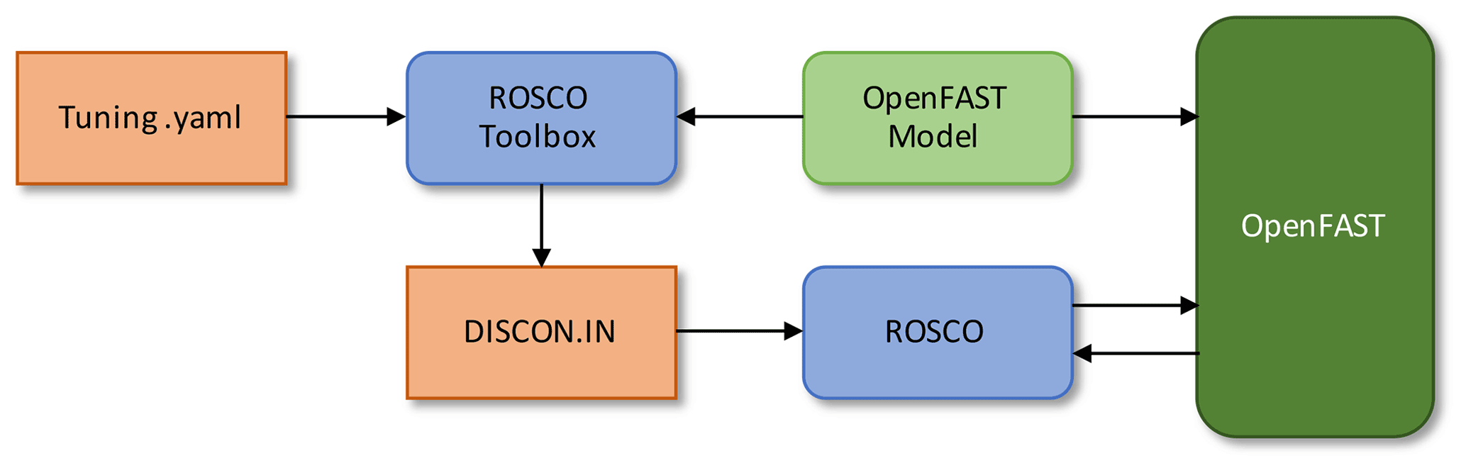
Figure 1The general workflow of the ROSCO tool chain. The orange squares denote ROSCO-related input files, the blue squares denote the ROSCO software tools themselves, and the green squares denote the OpenFAST wind turbine model and OpenFAST itself.
The work by Mulders and van Wingerden (2018) modularized the controller architecture and established an input file framework for the compiled Fortran code. Since then, numerous modules and controller features have been introduced and the functionalities of the controller have been expanded significantly into what is now ROSCO. In this article, we provide an overview of the primary controller modules that are generically tuned by the ROSCO toolbox or were added specifically for ROSCO.
2.1 Control regions
There are generally two methods of actuation in the standard reference wind turbine controllers, including ROSCO. A variable-speed generator torque controller is used to control the generator power, and a collective blade pitch controller is used to regulate rotor speed. These methods of actuation are commonly separated into four regions of operation, with transition logic between them. The steady-state operating points, as shown in Fig. 2 for the NREL 5 MW and International Energy Agency (IEA) 15 MW wind turbines, are a convenient way to visualize the regions of operation.
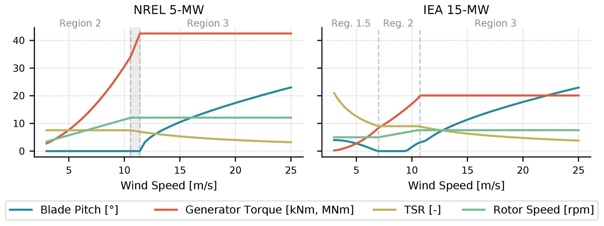
Figure 2The steady-state operating points for the NREL 5 MW and IEA 15 MW wind turbines with the ROSCO controller are shown to illustrate how the turbine operation changes in different regions for different types of controller implementation. The plotted operation points are based on the turbine parameters needed by the ROSCO toolbox tuning procedures and from the Cp surfaces generated by CCBlade (see Sect. 2.3). The different control regions are separated by the vertical grey dashed lines. Regions 1 and 4 are not shown. Region 2.5 is specified by the shaded area between Region 2 and Region 3 for the NREL 5 MW turbine, and does not specifically exist for the IEA 15 MW turbine (Gaertner et al., 2020). Constant torque operation is shown in Region 3 for both turbines. The pitch-saturation routine (see Sect. 5.3) used by the IEA 15 MW wind turbine results in the nonzero blade pitch trajectory in Region 1.5 and in the upper portion of Region 2 and beginning of Region 3. Also note that the generator torque is in kNm for the NREL 5 MW turbine and MNm for the IEA 15 MW turbine and that the y axis is shared for both plots.
In Fig. 2, regions 1 and 4 are considered to be below cut-in wind speed and above cut-out wind speed, respectively, so they are not of particular interest. Here, we provide a brief overview of each region and compare how they are implemented in the NREL 5 MW reference wind turbine controller versus ROSCO. In the following sections, we provide more in-depth descriptions of the logic and tuning processes.
Region 1 is when the wind speed is below the turbine's cut-in wind speed. This region is generally uninteresting for standard control purposes, and it is not shown in Fig. 2 for either turbine.
Region 1.5 is when the wind speed is above the turbine's cut-in wind speed, but the turbine cannot operate at its optimal tip speed ratio (TSR). In the traditional NREL 5 MW reference controller, a linear transition from no generator torque to the minimum optimal generator torque is used. In ROSCO, a proportional-integral (PI) controller modifies the generator torque to maintain a defined minimum rotor speed, and the blades are pitched to their minimum allowable blade pitch angle. In turbines designed to operate at a higher TSR in low wind speeds because of a minimum rotor speed constraint, minimum blade pitch angles can be scheduled by a wind speed estimate to improve power output (see Sect. 5.3.2). ROSCO's different Region 1.5 behaviors are shown in Fig. 2, where Region 1.5 does not span a specific range of wind speeds for the NREL 5 MW wind turbine because of the use of a PI controller, and increased blade pitch angles are seen in low wind speeds for the IEA 15 MW turbine.
Region 2 is when the wind speed is large enough that the turbine can operate at its optimal TSR but is still below rated. Here, the torque controller aims to maximize power as much as possible, and the blade pitch angle is fixed. In ROSCO, the generator torque controller either follows a traditional squared law (Bossanyi, 2000) or employs a TSR tracking PI controller (see Sect. 3.1.2) to track a rotor speed reference that is based on a wind speed estimate (see Sect. 5.1) and optimal TSR. The blades are pitched to fine pitch, where they are generally designed to be the most aerodynamically efficient.
Region 2.5 is when the wind speed is larger than the wind speed that corresponds with rated rotor speed, but less than the wind speed that corresponds with rated power. Here, the turbine operates in transition between regions 2 and 3. In the NREL 5 MW reference controller, a linear transition and switching logic are used across this transitional range of wind speeds. In ROSCO, a PI controller is used in both the pitch and torque controllers to regulate the rotor speed to their respective set points. A set point smoother (see Sect. 5.2) is used to ensure that only the pitch or torque controller is active at any point in time and that there is a smooth transition between them.
Region 3 is when the wind speed is above rated. The blade pitch controller regulates the rotor speed, and the generator torque is either constant or maintains constant power output. In ROSCO, a gain-scheduled PI collective pitch controller is used to regulate the rotor speed. For floating systems, the NREL 5 MW reference controller reduces the pitch controller bandwidth to prevent platform instability. In ROSCO, an additional feedback term is added to this controller for FOWTs (see Sect. 5.5) to help stabilize the platform using collective pitch, without the need to detune the rotor speed controller. The generator torque is either kept constant at its rated torque value, or the controller adjusts the torque to maintain constant power output.
Region 4 is when the wind speed is greater than the turbine's cut-out wind speed. Here, the blades are pitched to reduce rotor thrust to zero. Other than triggering a shutdown maneuver, this region is also generally uninteresting for standard control purposes and is not shown in Fig. 2.
In the case of the generator torque and blade pitch controllers, a generator speed signal is low-pass filtered and fed back to the respective controllers. The low-pass filter can be chosen as a first- or second-order filter, and the ROSCO toolbox tuning process generically tunes the cutoff frequency for the filter to be one-quarter of the blade's first edgewise natural frequency, as suggested in Jonkman et al. (2009). This helps prevent the controller from actuating at a frequency that excites the first edgewise mode of the blade.

Figure 3A block diagram showing the general controller logic in ROSCO. The shown signals in the figure are the primary time-varying signals passed between various parts of the controller; no constant set points or parameters are shown. The generator torque and collective blade pitch controllers described in Sects. 3 and 4, respectively, are shown in blue. The orange squares denote the various controller modules that are described in Sect. 5. The yellow squares are filters. The details of the floating filter are described in Sect. 5.5, and the standard low-pass filter implementations are provided in Appendix A. For the feedback signals, is the tower-top fore–aft velocity, β is the collective blade pitch angle, ωg is the generator speed, and τg is the generator torque. For outputs from the controller modules, βfloat is the floating controller's contribution to the blade pitch angle (see Sect. 5.5), βmin is the minimum blade pitch angle (see Sect. 5.3), is the estimated wind speed (see Sect. 5.1), and Δω is a controller reference set point shifting term from the set point smoother (see Sect. 5.2).
2.2 Implementation structure
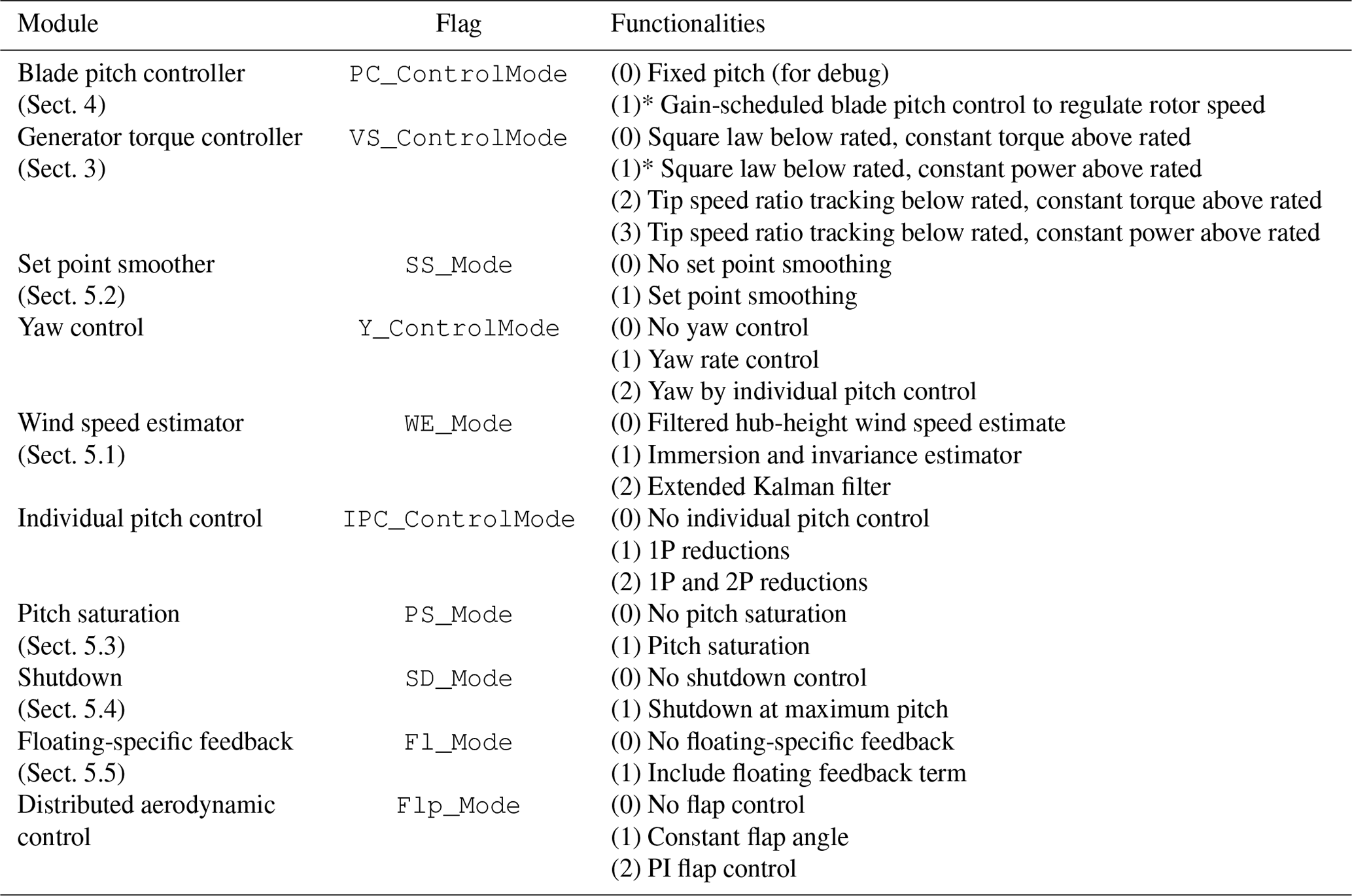
The high-level block diagram of ROSCO shown in Fig. 3 provides an overview of the control modules that are implemented in ROSCO. The combination of these modules ensures smooth actuation across the range of operation regions, as described in Sect. 2.1. Table 1 provides a brief description of each controller module.
Table 1The primary ROSCO modules and each of their available functionalities. The flag column shows the flag that must be set in the controller input file to activate each functionality. The functionalities column gives the possible flag values and a high-level description of available functions for each module. Section 5 gives more details of these functionalities. Modules with a section number reference in this table are primary modules that are discussed in more detail in this article. Functionalities with an asterisk denote functionalities that are used in the traditional NREL 5 MW wind turbine controller.
2.3 The power coefficient surface
Many tuning procedures and module implementations in this work are based on the so-called Cp surface. The power coefficient, Cp, is the ratio of the power extracted from the wind to the power available in the wind (Burton et al., 2011). For any given wind speed, the Cp surface can be calculated to represent the aerodynamic efficiency of the turbine as a function of collective blade pitch angle and TSR. The TSR is the ratio of the speed of the tip of the wind turbine blade to the rotor-averaged wind speed:
where ωr is the rotor speed, R is the rotor radius, and v is the wind speed. Similar parameter surfaces can be generated for the thrust and torque coefficients of the turbine, Ct and Cq, respectively. An example Cp surface is shown in Fig. 4 for the IEA 15 MW wind turbine (Gaertner et al., 2020).
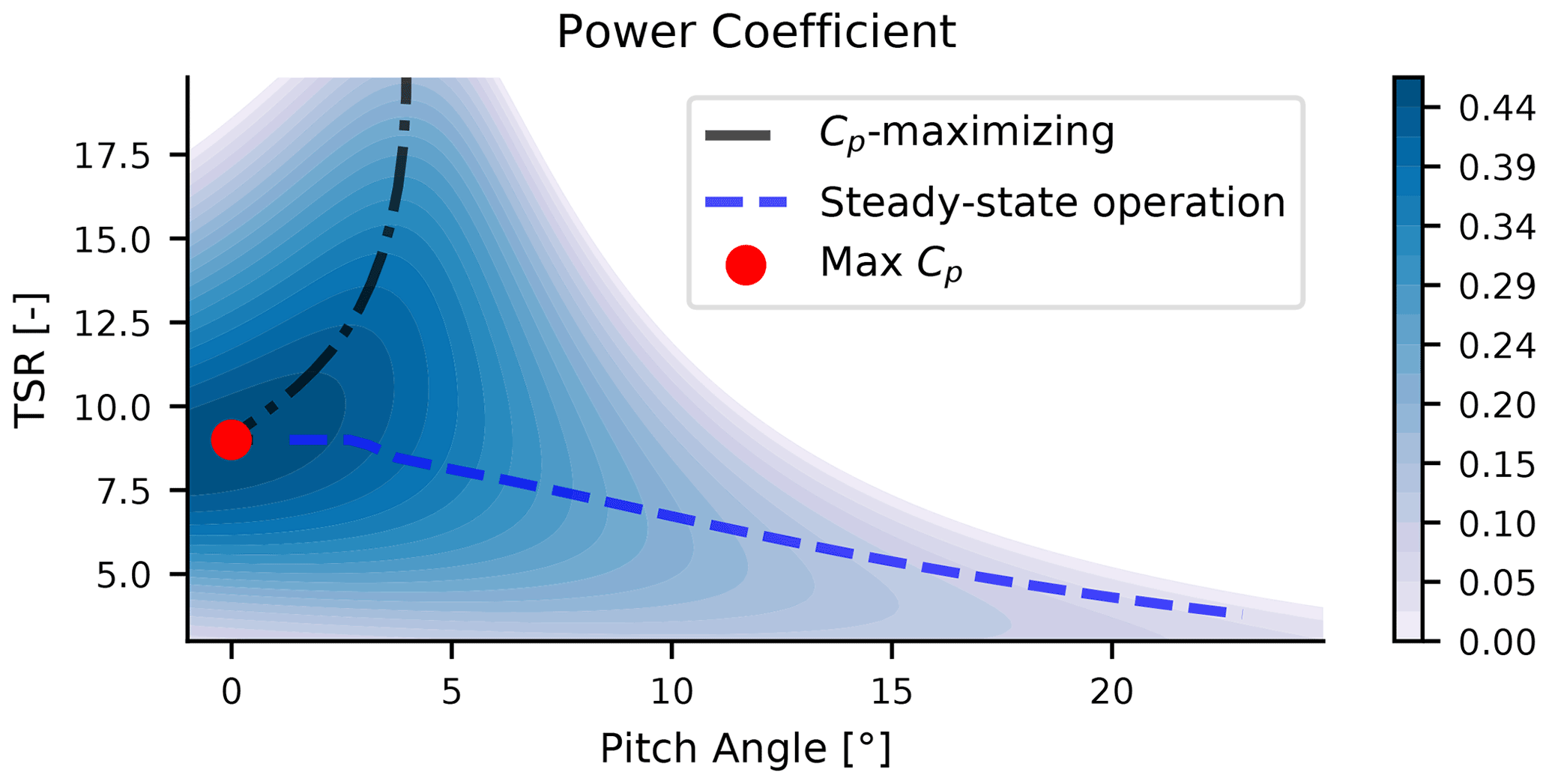
Figure 4Cp surface for the IEA 15 MW wind turbine. The dashed–dotted black line shows the below-rated steady-state operating points that result from a Cp-maximizing minimum pitch schedule at low wind speeds when the turbine has a minimum rotor speed constraint. The dashed blue line shows the expected steady-state operation points that are used to calculate the controller gain schedules.
The overlaid lines on the Cp surface shown in Fig. 4 represent the expected steady-state operation point of the wind turbine. The dashed–dotted black line shows the steady-state operating points at low wind speeds, where the TSR is high because of a constraint on the wind turbine's minimum rotor speed. By imposing a blade pitch angle that is greater than fine pitch at low wind speeds, the turbine can operate at a higher point on the Cp surface. In below-rated operation, the turbine is expected to operate with a fixed blade pitch angle and a constant TSR (see Fig. 2); this operation point is denoted by the red dot in Fig. 4. In above-rated wind speeds, the blades pitch to regulate the rotor speed, and there is a reduction in TSR (see Fig. 2), as denoted by the dashed blue line in Fig. 4.
In the standard ROSCO toolbox tuning procedure, the steady-state blade element momentum solver CCBlade (Ning, 2013) is used to find the Cp, Ct, and Cq surfaces quickly and efficiently. Similarly, parameter surfaces can be generated and written to a text file using any other blade element momentum or coupled aeroelastic solver. Using more complex solvers will, naturally, provide a more realistic Cp surface, though with a significant increase in computation time. Anecdotally, the authors have found the Cp surfaces generated using CCBlade to be sufficiently accurate for controller synthesis on numerous wind turbines thus far. Future work includes a more substantive analysis of the controller performance sensitivity to Cp surfaces generated using different aerodynamic solvers.
Within the ROSCO toolbox tuning processes, the Cp surface is primarily used to facilitate the calculation of the plant parameters, as discussed in Sect. 2.4. These parameters are used for tuning the blade pitch and generator torque controller gains and for accurate implementation of the wind speed estimator. The Cp surface is also used to determine the minimum blade pitch schedule in low wind speeds, if needed, and to determine the optimal below-rated TSR to maximize power output. Finally, the Cp surface is used within ROSCO itself so that the wind speed estimator can accurately estimate the operational state of the wind turbine. The Ct surface is used to determine the minimum blade pitch schedule for the so-called “peak shaving” routine, as described in Sect. 5.3.1.
2.4 Plant model
A number of generic tuning processes have been developed for the ROSCO controller. The first publication on this work (Abbas et al., 2020) provided an initial formulation of the primary tuning processes in ROSCO. By using simplified analytical models of the wind turbine, the need for numerical linearization routines using servo-aeroelastic codes such as OpenFAST is avoided. To define the simplified wind turbine for control systems development, a first-order model of the wind turbine is used (Pao and Johnson, 2011):
where the aerodynamic torque is
In Eq. (2), ωg is the generator speed, J is the rotor inertia, Ng is the gearbox ratio, τg is the generator torque, and ηgb is the gearbox efficiency. In Eq. (3), ρ is the air density, and Ar is the rotor area. The power coefficient Cp(λ,β) is found via lookup table. The first-order linearization of Eq. (3) at some nominal steady-state operational point is
where , , and , and “op” denotes the expected steady-state operational ωg, β, and v for any linearization point. Equation (2) can then be rewritten in a linearized form as
where Δ denotes a perturbation from the steady-state value. Equation (5) is the plant model used to define the generator torque and blade pitch controller gains, where
and λ is the tip speed ratio as defined in Eq. (1). The coefficients and Bβ(vop) are described in Sects. 3.1.2 and 4, where the blade pitch and generator torque controllers are described, respectively. To calculate the Cp surface gradients, a second-order central differencing approach is used.
This linearized plant model is used to separately tune above- and below-rated controllers. Note that Bv, the disturbance (Δv) input matrix to the system, is set to 0 for the controller tuning.
2.5 Proportional-integral reference tracking control
A reference tracking PI controller is used in above-rated and below-rated operation. The PI controller is generically defined as
where u is an input to the controller, y is the output from the controller passed to the wind turbine, and kp and ki are the proportional and integral gains, respectively. For example, the standard PI blade pitch controller has inputs and outputs such that
and the TSR tracking PI generator torque controller has inputs such that
In Eqs. (10) and (11), the generator speed error input, −Δωg, is defined as a perturbation from the reference speed such that
while Δβ and Δτg are perturbations from their respective nominal steady-state values such that
By combining the PI controller formulation in Eq. (9) with Eq. (10) or Eqs. (11) and (5), a differential equation relating the reference generator speed perturbation Δωg,ref and the actual generator speed perturbation Δωg is obtained. If we take the Laplace transform of this differential equation, the closed-loop transfer function from Δωg,ref=0 to Δωg results in
where B is either or Bβ(vop), depending on whether the turbine is in below- or above-rated operation, respectively. A block diagram to visualize this closed-loop system in above-rated operation is shown in Fig. 5. Note that Δωg,ref=0 because we would not like the rotor speed to differ from the reference value, ωg,ref.
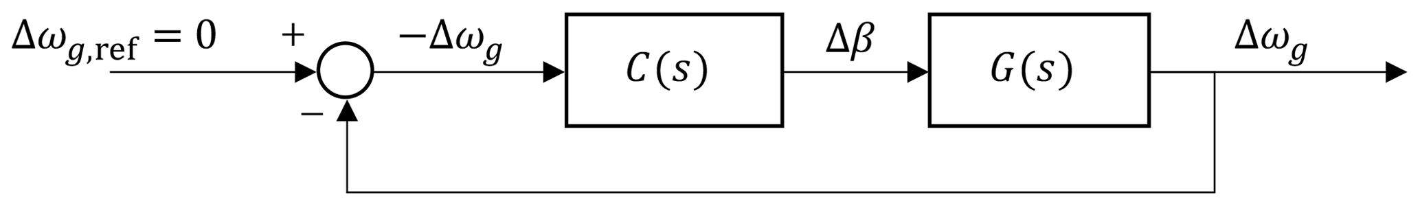
Figure 5A block diagram showing the closed-loop system used to tune the ROSCO controller in above-rated operation. The blocks C(s) and G(s) represent the controller and plant transfer functions, respectively.
This closed-loop system is a simple second-order system, so we define the PI gains as
where the closed-loop response is characterized by a desired natural frequency, ωdes, and damping ratio, ζdes. For a standard horizontal-axis wind turbine, B is negative in below- and above-rated operation, so ki and kp are negative. Therefore, based on this formulation, an increase in rotor speed results in and an increase in generator torque or blade pitch angle. By defining the desired natural frequency and damping ratio of the rotor speed response, the user can modify the dynamic response of the rotor to changes in the wind speed. Increased desired natural frequencies will decrease the response time of the rotor, whereas increased damping ratios will reduce the amount of oscillation in the response. To learn more about second-order system responses, the authors recommend Franklin et al. (2019) to the curious reader.
If PI controllers are employed for below- and above-rated operation, we are left with the need to define four controller tuning inputs. The choice of ωdes and ζdes for the below- and above-rated operating regions is the only parameter decision that needs to be made by the control designer or optimization routine, though additional tuning of the individual modules discussed in Sect. 5 might further improve controller performance.
2.6 Filters
Four filters are commonly used in the ROSCO controller (see Fig. 3): first- and second-order low-pass filters, a first-order high-pass filter, and a notch filter. Appendix A shows the continuous-time formulations of these filters. The filters are converted to discrete time for implementation using the bilinear transform.
Four total variable-speed generator torque control methods are available in ROSCO (see Table 1). Two methods of optimal power generation are available for below-rated operation, and two methods of maintaining power output near the turbine's rated value are available in above-rated operation.
3.1 Below-rated torque control
In below-rated operation, the generator torque controller's goal is to maximize power production. If the blades are pitched to fine pitch, maximum aerodynamic efficiency can be achieved and power can be maximized if the torque controller maintains the TSR corresponding to the peak of the Cp surface. In ROSCO, this is done in one of two ways.
3.1.1 Kω2 law
A study of Eq. (2) in steady state, such that , provides the foundation for the so-called “ law” for optimal torque control (Bossanyi, 2000; Johnson et al., 2006). By restructuring Eq. (2), and assuming that the wind turbine is operating at its optimal TSR, λopt, and corresponding power coefficient, Cp,max, one can realize a quadratic relationship between the generator speed and demanded generator torque. This relationship is commonly defined as
3.1.2 Tip speed ratio tracking torque control
Two primary motivations are behind the development of the TSR tracking controller in ROSCO. First, although the law has historically worked reliably in idealized simulation environments, the calculation of K can be subject to modeling and assumption errors. For example, the assumption that R is a constant value across wind speeds does not hold as strongly in modern, highly flexible rotors as it has in the past. Fortunately, modern rotors are still commonly designed to maximize aerodynamic efficiency at a specific TSR. Second, industry collaborators have indicated that a TSR tracking controller is more representative of the controllers often used in the field.
If the blades are pitched to their most aerodynamically efficient angle and the wind turbine rotor is operating at its optimal TSR, the turbine power is theoretically maximized. This suggests that if the wind speed can be measured or estimated accurately, a generator torque controller can be designed to maintain the rotor's λopt and maximize power capture. In ROSCO, a standard PI controller is used to track a generator speed reference. For the generator torque controller:
where is the estimated rotor-effective wind speed provided by the wind speed estimator described in Sect. 5.1. This reference signal is also constrained by
where ωg,min is the minimum allowable generator speed, and the subscript “rated” denotes the value as calculated at rated operation.
A straightforward and automated tuning process has been developed for the PI gains for the TSR tracking torque controller. With the assumption that the blade pitch is held constant at fine pitch in below-rated operation, Δβ=0 in Eq. (5). This means that in Eqs. (15) and (16) and is defined as
for the generator torque controller. With this, ωdes and ζdes can be chosen to describe the below-rated closed-loop rotor speed response, and Eqs. (15) and (16) can be calculated for the generator torque controller. Equation (15) suggests that kp(v) and A(v) are both dependent on v; however, it was found that fixing , where the subscript “vs” denotes variable-speed torque control, simplifies the controller implementation without negatively affecting power production or generator loads.
3.2 Above-rated torque control
There are two standard methods of actuating the generator torque in above-rated operation. Defining P as the generator power output, in above-rated operation the generator torque is defined to be
for constant torque or constant power output, respectively.
If the law is used for below-rated torque control, the torque controller switches to above-rated operation when the blades are pitched beyond an offset, denoted by PC_Switch in the DISCON.IN file. When the turbine is in above-rated operation, the generator torque is then defined directly by the relationships in Eq. (21). If the TSR tracking control is used for below-rated operation, the above-rated generator torque output is simply constrained such that τg(t)≤τg,ar(t). In above-rated operation, the set point smoother (see Sect. 5.2) shifts the reference generator speed such that the generator torque is saturated at its maximum allowable value, resulting in either constant torque or constant power output.
If constant torque control is used, power output changes are directly correlated to the changes in the generator speed in above-rated operation. If constant power control is used, there are still some changes in power output because ωg(t) in Eq. (21) is low-pass filtered, but the power is more consistent than in the constant torque case. As discussed by Jonkman (2010), using a constant generator torque controller in above-rated operating conditions can help improve FOWT platform stability.
In below-rated operation, the generator speed is less than the rated generator speed, so the blade pitch angle, β, saturates at β=βmin. This is generally the fine-pitch angle, unless a pitch saturation schedule is implemented, as described in Sect. 5.3.
In above-rated operation, a PI controller is used to determine the collective blade pitch angle to keep the turbine at a rotor speed reference. The above-rated rotor speed reference ωg,ref for the blade pitch controller is generally defined as
It is well established, and common in reference controllers, to employ a gain schedule to improve blade pitch controller performance (Jonkman et al., 2009; Hansen and Henriksen, 2013; Mulders and van Wingerden, 2018). In the ROSCO toolbox we use the Cp surface to prescribe this gain schedule, rather than using aero-servo-elastic linearization tools.
When tuning the pitch controller's gain schedule, we cannot directly assume that the generator torque is kept constant because it may change if constant power operation is used. In constant power operation, the first-order Taylor series expansion of the generator torque in Eq. (21) is
Considering that the generator torque as defined by Eq. (13) can be rewritten as in above-rated wind speeds, we define
If constant power operation is used, then A(vop) in Eq. (6) is re-defined to
For constant torque operation, it can be assumed that Δτg=0, so no modifications are made to A(vop). In both cases, B in Eqs. (15) and (16) is
For any wind speed vop, the expected steady-state Cp,op can be calculated by (Bottasso and Croce, 2009)
Through the relationship in Eq. (27) and the Cp surface, we can find the expected blade pitch angles, βop(λop), for any TSR. In steady-state above-rated operation the generator speed is considered to be constant, so the TSR is only a function of the wind speed, and we can define βop(v). This enables us to change A(vop) and Bβ(vop) to be A(βop) and Bβ(βop) for controller tuning purposes. Equations (15) and (16) are then defined for the blade pitch controller to be kp,pc(βop) and ki,pc(βop), and the blade pitch controller gain schedule can be implemented as a function of blade pitch angle rather than an estimated wind speed. In the ROSCO implementation of the blade pitch controller, a low-pass-filtered blade pitch angle, βlpf, is used to interpolate the necessary pitch controller gains, kp,pc(βlpf(t)) and ki,pc(βlpf(t)), for the PI controller at each time step.
Notably, the Cp surface gradients used to calculate both A(vop) and B(vop) approach zero near the “peak” of the Cp surface. Because Bβ(vop) is in the denominator of Eqs. (15) and (16), the gains would theoretically approach infinity near rated operation. To avoid unrealistically high gains, A(vop) and B(vop) are each approximated by a linear fit for the blade pitch controller gain calculation in the ROSCO toolbox. With this foundation, the blade pitch controller's gain schedule can be generated using the ROSCO toolbox for any user-defined ωdes and ζdes.
ROSCO is modularized such that various control methods can be switched on and off without the need to recompile any code. Here, we present the theoretical foundations for the module implementations and their respective generic tuning processes.
5.1 Wind speed estimator
In this section, we discuss the wind speed estimator used in ROSCO. The wind speed estimate is used in the TSR tracking generator torque controller (see Sect. 3.1.2) and pitch saturation (see Sect. 5.3) routines. The employed wind speed estimator is inspired by Knudsen et al. (2011) and is based on a continuous–discrete extended Kalman filter. The theoretical background of the continuous and discrete time extended Kalman filters used in this work is further detailed in Grewal and Andrews (2014). The Kalman filter uses informed definitions of the covariance matrices based on the expected wind fields to provide a wind speed estimate, . The derivatives are evaluated in continuous time, whereas the measurement updates are evaluated in discrete time. A forward Euler integration method is used to propagate the state and covariance estimates forward in time.
The nonlinear continuous-time state-space model used for the continuous–discrete Kalman filter implemented in the controller is defined as
where the system noise is ξs=[n1 n2 n3]T, and ni is considered to be zero-mean white noise. The measurement noise, ξm, is assumed to be white noise with a constant covariance. The system state, inputs, and outputs are defined as
where vt is the turbulent component of the wind speed, and vm is the mean wind speed. The nonlinear state equations are defined as
and the output is
To complete the state equation definitions, we establish
In Eq. (36), L is a turbulence length scale parameter generically defined as L=3D, where D is the rotor diameter.
In the Kalman filter, the covariance matrices are based on the wind model as defined by Knudsen et al. (2011). In the ROSCO implementation of this wind speed estimator, the process noise (Q) and measurement noise (Rm) covariances are
where the turbulence intensity is defined as ti=0.18, the upper limit of the turbulence intensity for standard inflow wind conditions as defined by IEC (2019). A continuous–discrete Kalman filter is then implemented through the following formulation:
-
Prediction update
-
Measurement update
Here the state transition and output Jacobians are defined as
Wind speed estimator results from a 10 min simulation of the NREL 5 MW turbine are shown in Fig. 6. In the presented simulation, the root-mean-square error between the rotor-averaged wind speed and the wind speed estimate is 0.48 m s−1.
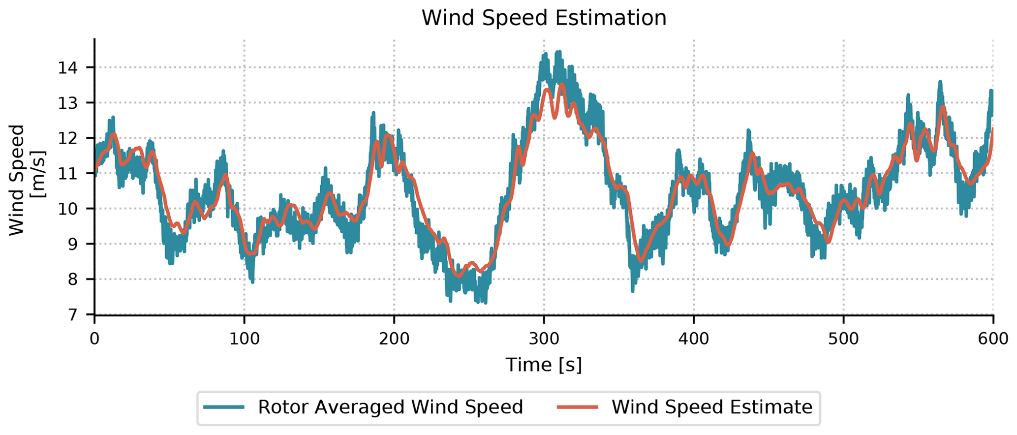
Figure 6Wind speed estimator results for the NREL 5 MW wind turbine with 10 min of simulation time and an average wind speed of 11 m s−1.
5.2 Set point smoothing
The generator torque and blade pitch controllers will conflict with each other in near-rated operation if the generator torque and blade pitch reference speeds are defined only by Eqs. (19) and (22). To avoid this, we employ a set point smoother regime that is akin to a Region 2.5 controller (Schlipf, 2019; Zalkind and Pao, 2019). Practically, the so-called “set point smoother” shifts the generator speed reference signal of the saturated controller while the unsaturated controller is active, so the controllers do not have conflicting behaviors. This encourages one controller to stay active while the other is not.
We first define an offset to the rotor speed set point, Δω, as
where kvs and kpc are unitless gain factors that are greater than 0, and βmax is the blade pitch angle at cut-out wind speed. Equation (48) is defined such that Δβ=0 in below-rated operation and Δτ=0 in above-rated operation. A piecewise logic is then implemented to shift the blade pitch or generator torque reference generator speeds:
Figure 7 shows a block diagram displaying the set point smoother logic.
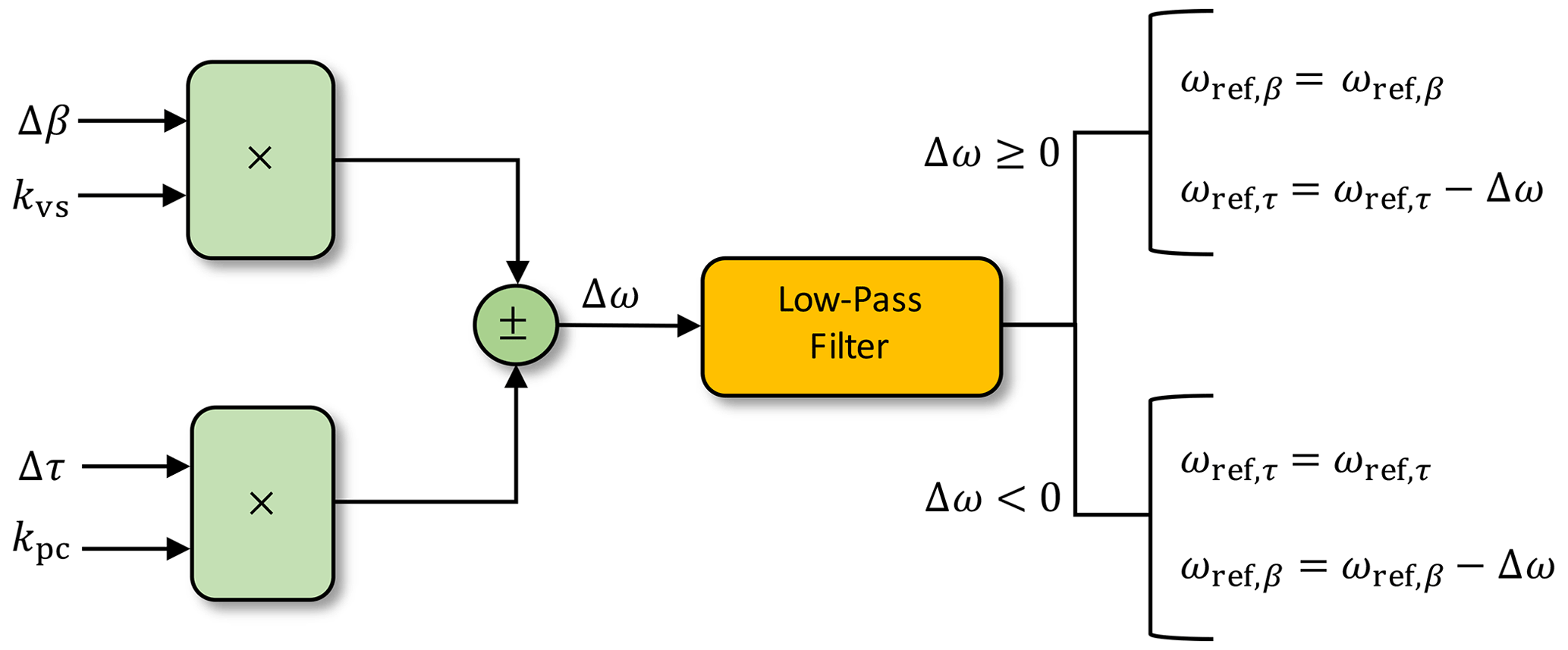
The shifting term in the set point smoother defined in Eq. (48) includes normalization terms, so no specific tuning is necessary. The ROSCO toolbox tuning processes define kvs=1 and . These values were chosen because of their utility across turbine models, although specific tuning of these can improve the controller performance near rated operation.
Figure 8 shows results from a 10 min time-domain simulations of the NREL 5 MW wind turbine near rated operation. The set point smoother employed in ROSCO provides significantly smoother transitions from above- to below-rated operation. When the blade pitch is greater than zero (the first 12 s in Fig. 8), the torque controller set point decreases, which biases the generator torque toward its maximum value. When the generator torque is less than its rated value (the last 12 s in Fig. 8), the set point for the pitch controller increases, and it biases the pitch to its minimum value. The smoother shifts the saturated controller's set point linearly depending on how “far” it is from rated operation. By separating the control regions this way, resonances such as those seen in the time history of the NREL 5 MW torque controller's signal between 15 and 25 s can be reduced.
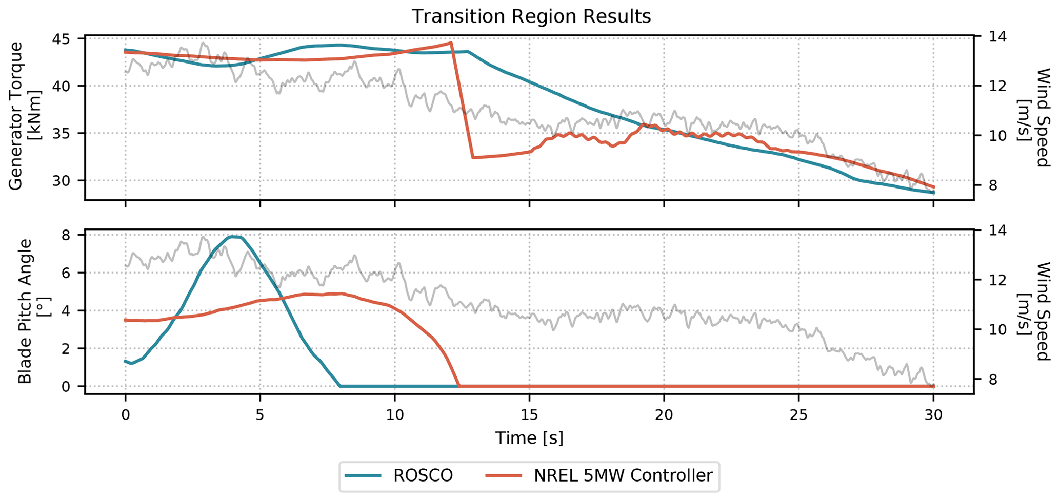
Figure 8Time-domain simulation results from the NREL 5 MW wind turbine near rated wind speeds. The rotor-averaged wind speed is plotted in the background as grey curves in each plot.
5.3 Minimum pitch saturation
A method for saturating the minimum blade pitch angle for a given wind speed estimate is also included in ROSCO. This has primarily been used for two purposes: to limit the rotor thrust through a peak shaving algorithm and to implement a minimum pitch angle at low wind speeds for power maximization in the presence of a minimum rotor speed constraint. The ROSCO controller simply defines a minimum blade pitch angle for a given wind speed as specified by a lookup table in the DISCON.IN file. Figure 9 provides an example minimum pitch schedule for the IEA 15 MW wind turbine with a minimum rotor speed constraint and peak shaving, along with the corresponding rotor thrust that is expected with and without peak shaving.
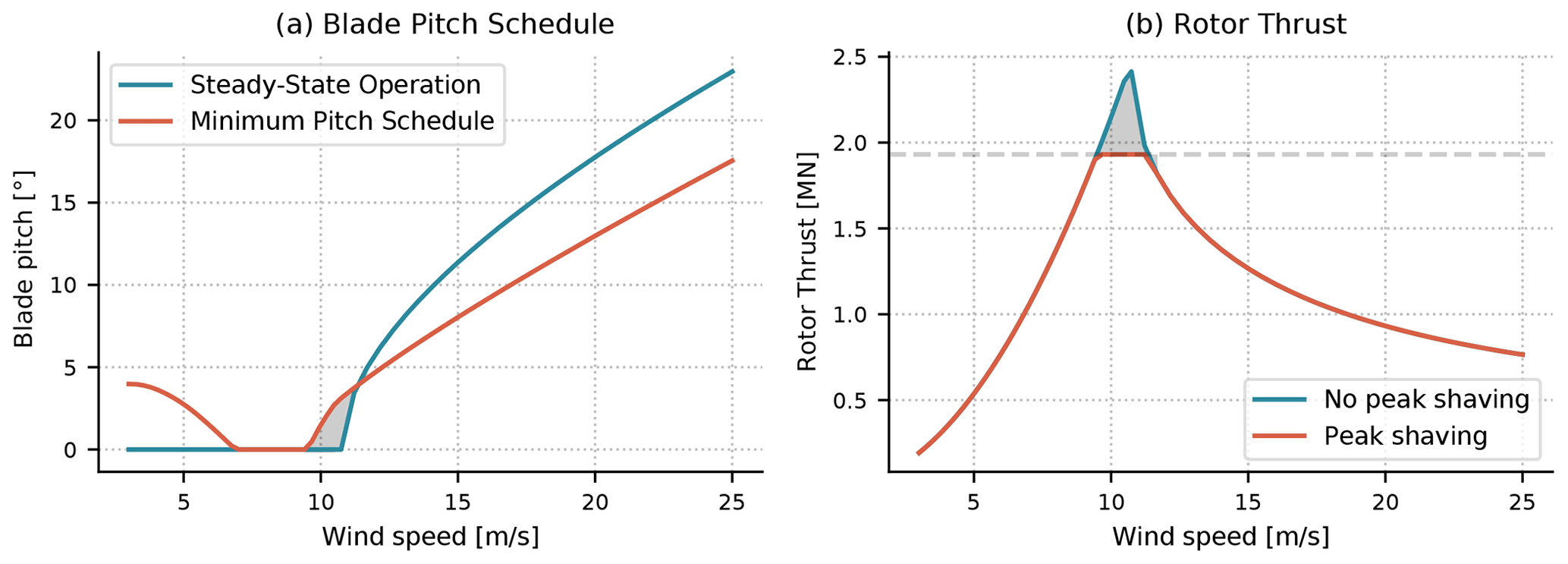
Figure 9Expected steady-state pitch saturation for the IEA 15 MW wind turbine, based on the Ct surface calculated with CCBlade. The blade pitch schedule (a) shows the expected steady-state value of the pitch angle along with the imposed minimum pitch angles with pitch saturation for both peak shaving and power maximization in low wind speeds. The right-hand plot (b) shows the expected rotor thrust with and without peak shaving. The grey region in the blade pitch schedule corresponds to the pitch angles that result in a rotor thrust above the maximum allowable thrust, shown as the grey region in the right-hand plot (b).
The following two subsections describe the two primary aspects of the minimum pitch schedule in more detail.
5.3.1 Peak shaving
Thrust limiting, or peak shaving, is often used to reduce peak tower base loads. Generally, the largest rotor thrusts are seen near rated operation and have a strong effect on tower base loads. It is has also been shown that rotor thrust is correlated to the blade pitch actuation (Bossanyi, 2003; Fischer and Shan, 2013; Petrović and Bottasso, 2017). We impose a minimum blade pitch angle, βmin(v), to “shave” the peak of the rotor thrust curve and subsequently reduce tower base loads near rated. The rotor thrust can be defined by
where Ct is the rotor thrust coefficient. Given a maximum allowable rotor thrust, , where a≤1, the maximum allowable thrust coefficient is defined as
For all operational TSRs, we can find a blade pitch angle, βmin(Ct,max,λ), through a Ct surface similar to the Cp surface shown in Fig. 4. Notably, Ct,max(v) and λ are both parameterized by v, so we can define a minimum blade pitch schedule, βmin(v), that is dependent on a wind speed estimate. Figure 10 shows an example 60 s time series for the NREL 5 MW wind turbine in near-rated operation. Based on the wind speed estimate, the blades are pitched to reduce the rotor thrust to stay at or below the maximum allowable thrust limit.
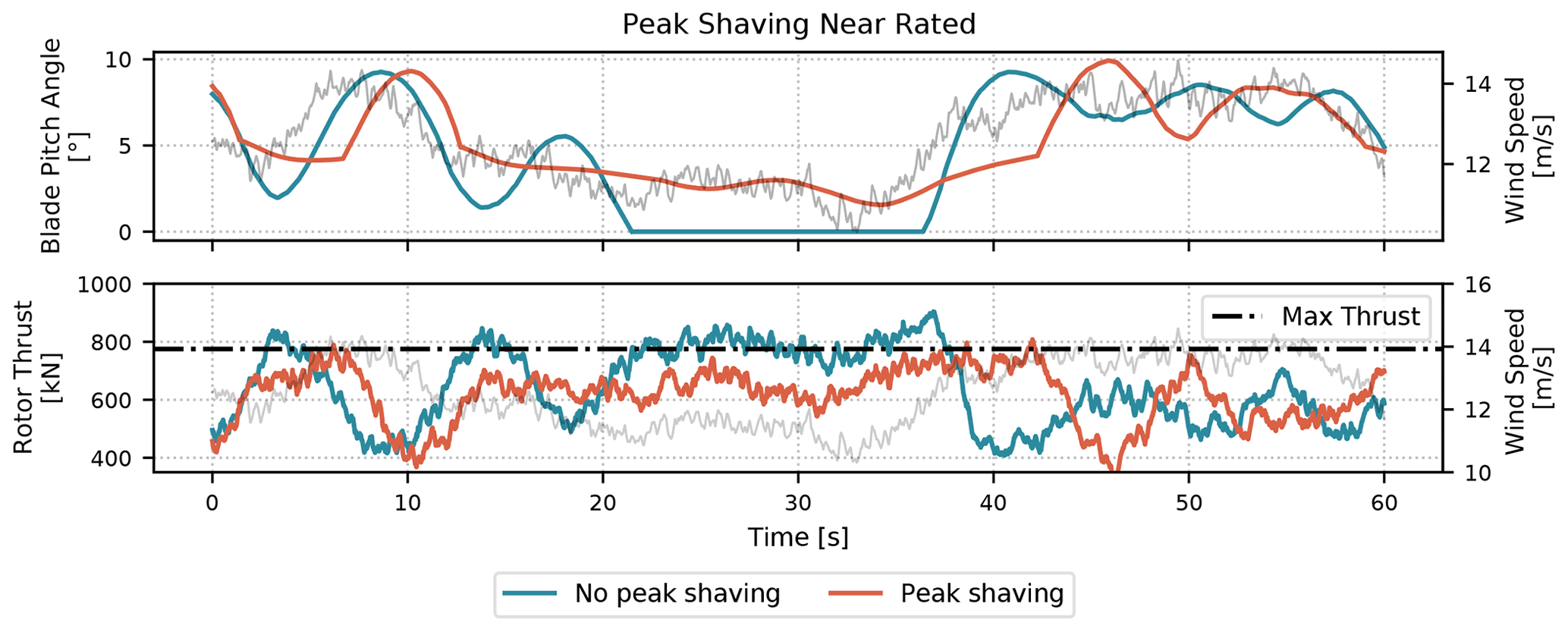
Figure 10A sample 1 min time series from a 10 min turbulent simulation of the NREL 5 MW wind turbine to showcase the peak shaving routine in ROSCO. The peak shaving percentage was tuned to 20 % for this simulation. The wind speed is shown in the background of each plot, and the maximum allowable thrust is denoted by the dashed–dotted black line in the lower plot.
Peak shaving algorithms implemented with minimum pitch saturation can result in power losses because the turbine will no longer be operating at its highest efficiency near rated. Though the default peak shaving algorithm in the ROSCO toolbox reduces the maximum rotor thrust by 25 %, ultimately the trade-off between power production and load reductions must be made by the control system designer.
5.3.2 Power maximization in low wind
In certain wind turbine configurations, such as the IEA 15 MW wind turbine (Gaertner et al., 2020), minimum or maximum blade tip speed limits might be imposed for reasons such as tower resonance avoidance or noise avoidance. If a minimum tip speed constraint exists, the wind turbine cannot operate at λopt in low wind speeds. A minimum pitch schedule can be implemented such that the power can be maximized in low wind speeds while the generator torque controller works to satisfy the minimum rotor speed constraints. The black dashed–dotted line in Fig. 4 provides insight into how the power output can be improved through a minimum pitch angle at low wind speeds by moving the turbine's expected operating point to the “top” of the Cp surface for high TSRs.
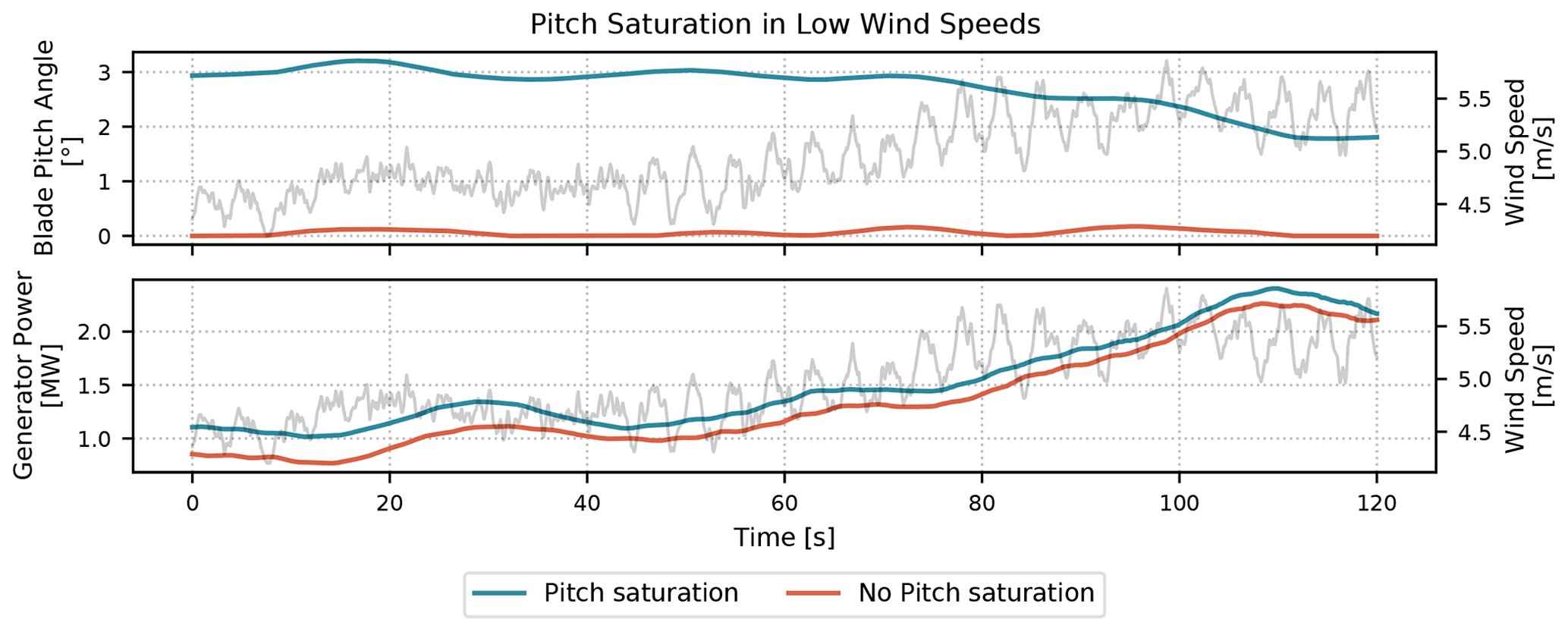
Figure 11A sample 2 min time series from a 10 min turbulent simulation of the IEA 15 MW wind turbine showing how increased blade pitch angles can increase power output at low wind speed. The rotor-averaged wind speeds are plotted in grey in the background.
Figure 11 shows an example of how the power can be increased. A 10 min simulation was run in OpenFAST for an inflow wind with normal turbulence and a 5 m s−1 average wind speed. With the pitch saturation module turned on, the blade pitch angle is changed based on the wind speed estimate and the pitch saturation lookup table, resulting in a slightly increased power output.
5.4 Shutdown
A simple shutdown routine is included in ROSCO for shutdown during high wind speed events. A first-order low-pass-filtered blade pitch angle signal triggers turbine shutdown if it exceeds a certain threshold. If the shutdown is initiated, the blades are pitched to feather at their maximum pitch rate to slow down the rotor. If the TSR tracking torque controller is being used, ωref,τ is set to the minimum rotor speed. This encourages the torque controller to help slow down the rotor initially. Once the blades are pitched such that very little lift is generated and the rotor is nearly stopped, the torque controller will saturate at zero in an unsuccessful attempt to speed up the rotor to the minimum rotor speed.
It is shown in Bottasso et al. (2014) that there are shutdown methods that could reduce possible design-driving loads during shutdown. Future work includes the investigation and inclusion of these methods in the ROSCO controller. Additionally, a number of events can trigger wind turbine shutdowns, such as generator overspeeds and yaw misalignment. Future work also includes the addition of improved shutdown event detection and control methods for such cases.
5.5 Floating offshore wind turbine feedback
An additional control feedback term is included to account for FOWTs in a method referred to as “parallel compensation” (Van Der Veen et al., 2012). The tower-top acceleration is filtered, integrated, and multiplied times a proportional gain feedback, . This modifies the blade pitch control signal to become
where xt is the tower-top position in the fore–aft direction. The block diagram in Fig. 3 provides a visualization of how this signal is implemented.
Although some research suggests the use of a platform pitch feedback signal for FOWT control (Fleming et al., 2014, 2016), the nacelle fore–aft signal is used in ROSCO so that the overall controller implementation can maintain the structure of the Bladed-style communication interface (DNV-GL, 2018). A first-order high-pass filter combined with a second-order low-pass filter are used to filter the nacelle fore–aft acceleration signal. The ROSCO toolbox generically places high- and low-pass filter cutoff frequencies at 0.01 rad s−1 and the platform's first fore–aft natural frequency, respectively. Additionally, a notch filter is used to remove the tower fore–aft frequency component of the feedback signal for the floating controller. A Bode diagram of the final form of this filter is shown in Fig. 12 for the IEA 15 MW wind turbine on the University of Maine (UMaine) semisubmersible platform (Allen et al., 2020). After this nacelle fore–aft acceleration signal is filtered and integrated, it is similar to a platform pitching velocity signal that is often used for FOWT control.
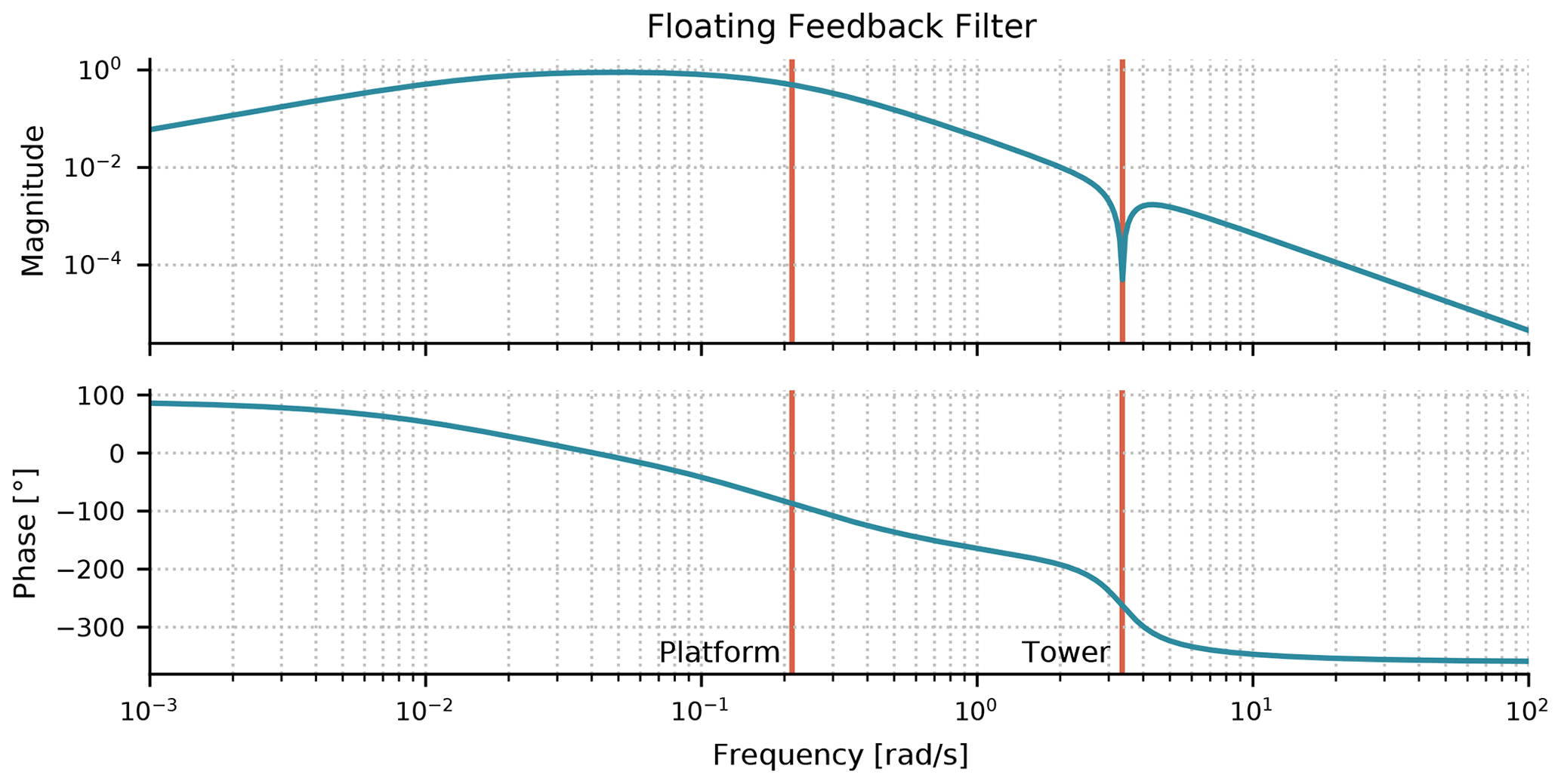
Figure 12A Bode plot showing the filter used for the tower-top motion feedback signal for the IEA 15 MW turbine on the UMaine semisubmersible platform. The first platform and tower fore–aft natural frequencies are shown in red and labeled accordingly. These natural frequencies are inputs to the ROSCO tuning process to shape this filter.
For consistency with the theme of the ROSCO tool set, a generic tuning process has been developed for this floating feedback term. We start by defining the simplified second-order equation of tower-top motion as
where Jt is the total system inertia in the platform pitching direction, ct is a damping constant, kt is a restoring constant, and Tr is the rotor thrust as defined by Eq. (50). The rotor effective wind speed is modified by tower motion such that
where Δvw is the change in free-stream wind speed. Similar to the derivation of Eq. (4), we can linearize Eq. (50) to be
where , , and .
For the controller, we have suggested that a proportional feedback term should be added to the standard blade pitch PI controller, such that the control input should be defined by Eq. (52). We also define the generator position as θ such that
After substituting Eqs. (52) and (54)–(56) in Eqs. (53) and (5), we arrive at the equations of motion for the closed-loop tower-top (Eq. 57) and rotor (Eq. 58) dynamics:
If we then convert Eqs. (57) and (58) into the state-space form , where
we can define
Note that A(4,2) is the state transition term from to . This suggests that if , then the tower-top pitching velocity will have no direct effect on the rotor acceleration. To attempt to achieve this, we define
Including the additional parallel compensation term βfloat reduces the need to detune the standard blade pitch PI controller because of the infamous negative-damping problem (Larsen and Hanson, 2007). If tuned appropriately, the parallel compensation term can help negate the effect of tower-top motion and subsequent changes to the relative wind speed at the rotor. Additionally, combining the use of this βfloat feedback term with a peak shaving routine from Sect. 5.3.1 can reduce the tower-top pitching transients and further stabilize the system. Though the peak shaving does, theoretically, reduce power output near rated operation, the tower-top stabilization benefits generally outweigh the power losses because less fore–aft tower motion can lead to increased power output.
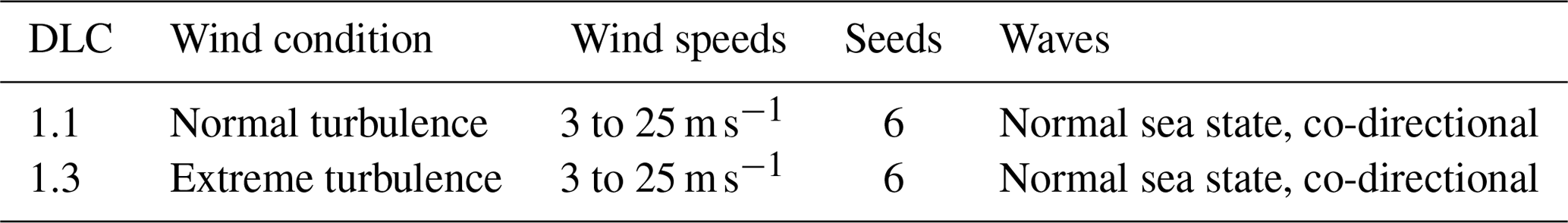
In this section, we use ROSCO v2.3.0 and present results from both land-based and floating wind turbine simulations. First, the ROSCO controller, as tuned by the ROSCO toolbox, is compared to the NREL 5 MW wind turbine controller using the land-based NREL 5 MW wind turbine. Then, results from the IEA 15 MW atop the UMaine semisubmersible floating wind turbine configuration are shown to illustrate the effect of the FOWT βfloat control feedback loop. The subset of the International Electrotechnical Commission (IEC) design load cases (DLCs) (IEC, 2019) shown in Table 2 were run for both turbines to offer a comparison of controller performance.
Table 2Simulated DLCs to showcase the difference in controller performance. The wind speeds were separated by increments of 2 m s−1, with normal and extreme turbulence models defined by the IEC (2019) standards. The sea-state-related inputs are relevant only for the FOWT simulations. Simulations were run for codirectional waves (i.e., wind and waves are aligned) to isolate the negative-damping phenomenon that is generally of interest to the control designer.
6.1 NREL 5 MW land-based wind turbine results
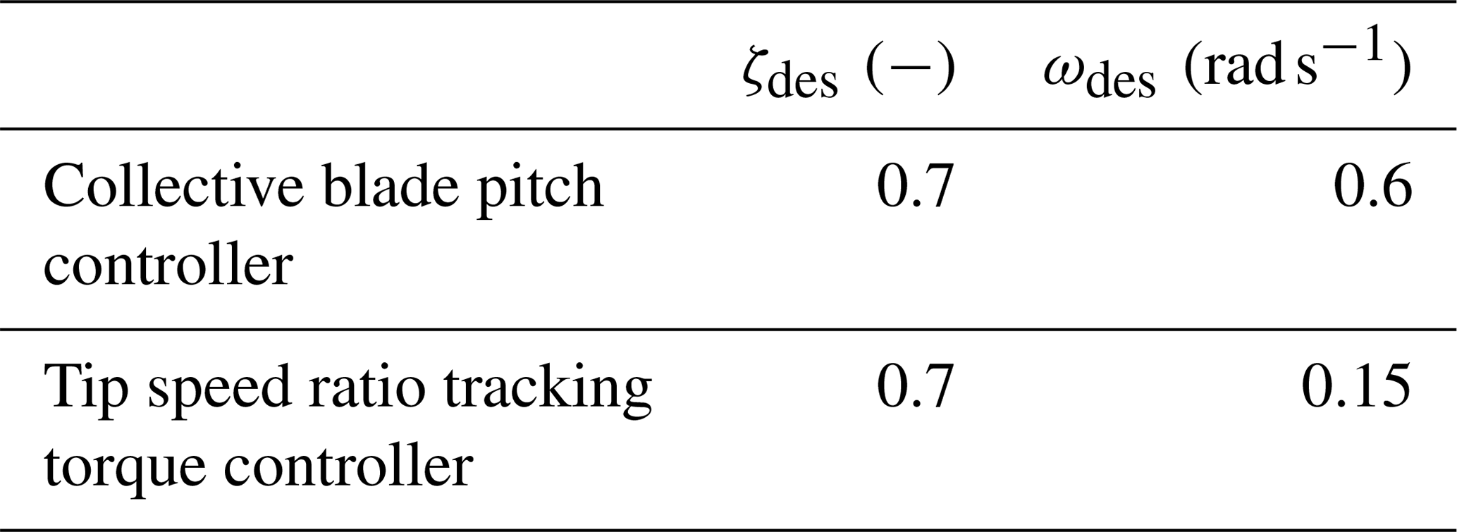
The land-based NREL 5 MW turbine with the NREL 5 MW wind turbine controller is compared to ROSCO with the ROSCO toolbox generic tuning values and ROSCO with minimal manual tuning and peak shaving implemented. As previously stated, there are only four necessary tuning parameters when tuning ROSCO using the generic ROSCO toolbox tuning functionalities. For the NREL 5 MW configuration, the choices for ζdes and ωdes are shown in Table 3. The controller tuning parameters used for ROSCO's pitch controller in the results presented in this section were chosen to be the same as those used for scheduling the gains of the NREL 5 MW reference controller. ROSCO's TSR tracking torque controller was tuned manually so that below-rated simulations resulted in consistent TSR tracking.
Table 3ROSCO controller tuning values for the collective blade pitch and TSR tracking torque controllers for the DLC simulations of the NREL 5 MW wind turbine.
The collective blade pitch controller gain schedules from the ROSCO tuning process are similar to those from the NREL 5 MW reference controller's tuning process, but they are not the same. The NREL 5 MW reference controller's gain schedule is based on the turbine's sensitivity of aerodynamic power to the collective blade pitch angle, a value that has generally been found using more computationally expensive aeroelastic solvers, whereas the ROSCO tuning process depends directly on the Cp surface.
High-level comparison results of the ROSCO controller compared to the NREL 5 MW reference controller are shown in Fig. 13. Results are shown from both the generic ROSCO controller and a ROSCO controller with peak shaving. For the ROSCO controller with peak shaving, all controller tuning input parameters were kept the same as for the generic ROSCO controller with the exception of implementing the standard peak shaving routine. The results from the generic ROSCO controller are consistent with the expected steady-state operating points shown in Fig. 2. In the results from the generic ROSCO controller, there is a noticeable increase in rotor thrust compared to the NREL 5 MW reference controller. This is attributed to the difference in pitch controller gains, and it can be mitigated with slightly different controller tuning parameters. Also, note that the NREL 5 MW reference controller exhibits significantly higher TSRs because of the torque controller's linear transition between regions 1 and 2 (Jonkman et al., 2009) rather than the PI controller-based transition that is used in ROSCO. The ROSCO controller tracks the optimal TSR of 7.5 well during below-rated operation.
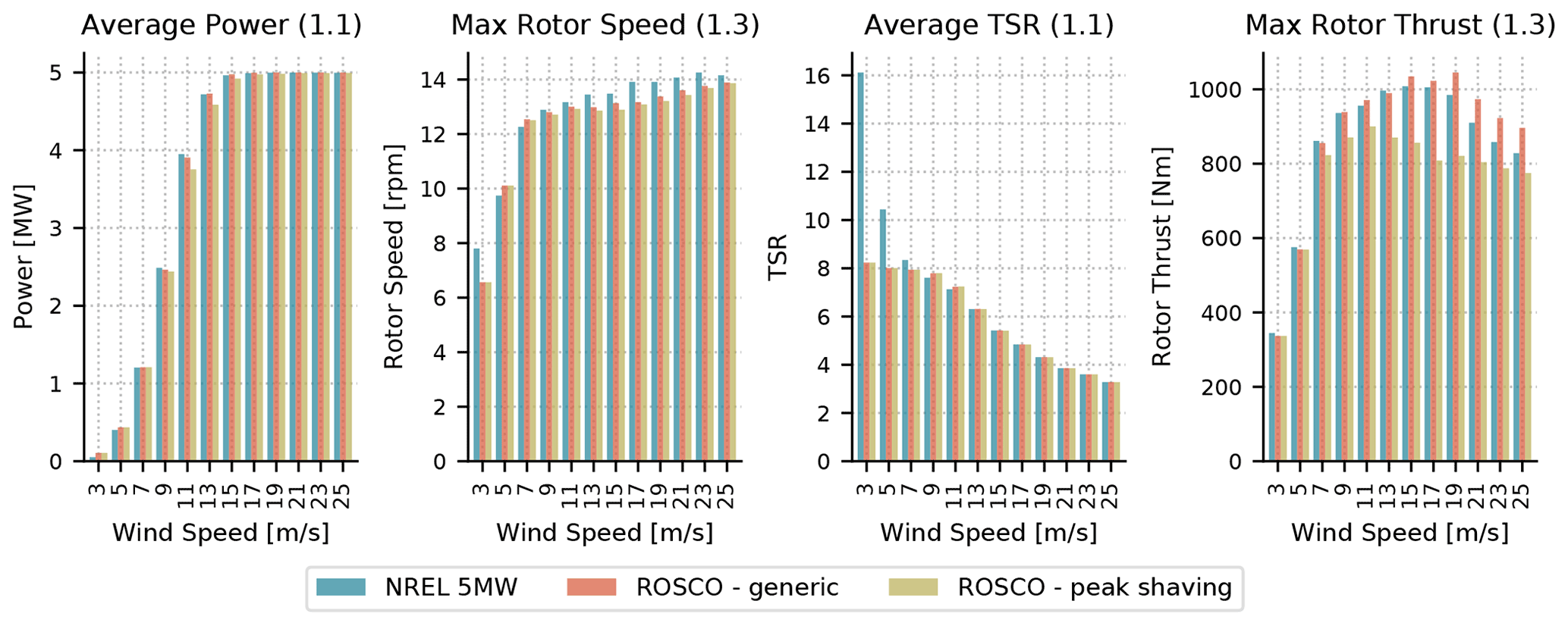
Figure 13Results from simulations of the NREL 5 MW land-based wind turbine. Average power, maximum rotor speeds, average TSRs, and maximum rotor thrusts are shown for DLCs 1.1 and 1.3. The dynamic results from the ROSCO controller are comparable to those from the NREL 5 MW reference controller. “ROSCO - generic” refers to ROSCO with the most generic tuning methods, and “ROSCO - peak shaving” refers to ROSCO with peak shaving implemented.
The power output and subsequent annual energy production from the ROSCO controller without peak shaving is 0.1 % greater than that of the NREL 5 MW reference controller. This is consistent with observations by Holley et al. (1999) and Bossanyi (2000), who note that minor energy production gains are possible to be achieved through an optimal TSR-tracking controller, though at the cost of more generator power fluctuations. In fact, the maximum standard deviation of the power output during DLC 1.1 decreased by 1.5 % when using ROSCO instead off the NREL 5 MW reference controller, so no significant power increases are expected. The annual energy production from the ROSCO controller is 1.7 % less than that of the NREL 5 MW reference controller when the peak shaving routine is implemented in ROSCO. This is expected because rotor thrust reductions reduce the wind turbine's power output as well. Notably, the maximum rotor thrust seen is slightly higher than the expected maximum rotor thrust (see Fig. 10). This is attributed to the imperfect nature of a peak shaving routine based on a wind speed estimate, and it could likely be improved through an observer-based rotor thrust shaving algorithm or similar. The peak shaving also helps to both mitigate rotor thrusts introduced by the initial ROSCO tuning and reduce them further than those from the simulations using the NREL 5 MW reference controller.
6.2 IEA 15 MW on the UMaine semisubmersible FOWT results
We compare results from the IEA 15 MW wind turbine on a semisubmersible floating turbine platform for the ROSCO controller with and without the floating feedback and peak shaving modules enabled (see Fig. 3). Larsen and Hanson (2007) suggest that the tuned bandwidth of a rotor speed-regulating collective blade pitch controller should not be higher than the platform's first fore–aft eigenfrequency. This method of “derating” the blade pitch controller has traditionally been employed in baseline FOWT controllers, such as the NREL 5 MW OC3- and OC4-Hywind FOWT models (Jonkman, 2010; Robertson et al., 2014). Though derating the turbine can provide stable platform dynamics, generator overspeeds can generally be very high with this method of control. The standard distribution of the IEA 15 MW wind turbine on the UMaine semisubmersible platform (IEA Wind Task 37, 2021) employs ROSCO, and the pitch controller bandwidth is 0.2 rad s−1, which is already less than the UMaine semisubmersible's first platform eigenfrequency of ∼0.21 rad s−1. Also, the IEA 15 MW wind turbine uses constant generator torque control in above-rated operation. For this comparison, the floating feedback and peak shaving modules are either enabled or disabled, and the rest of the controller is not changed at all.
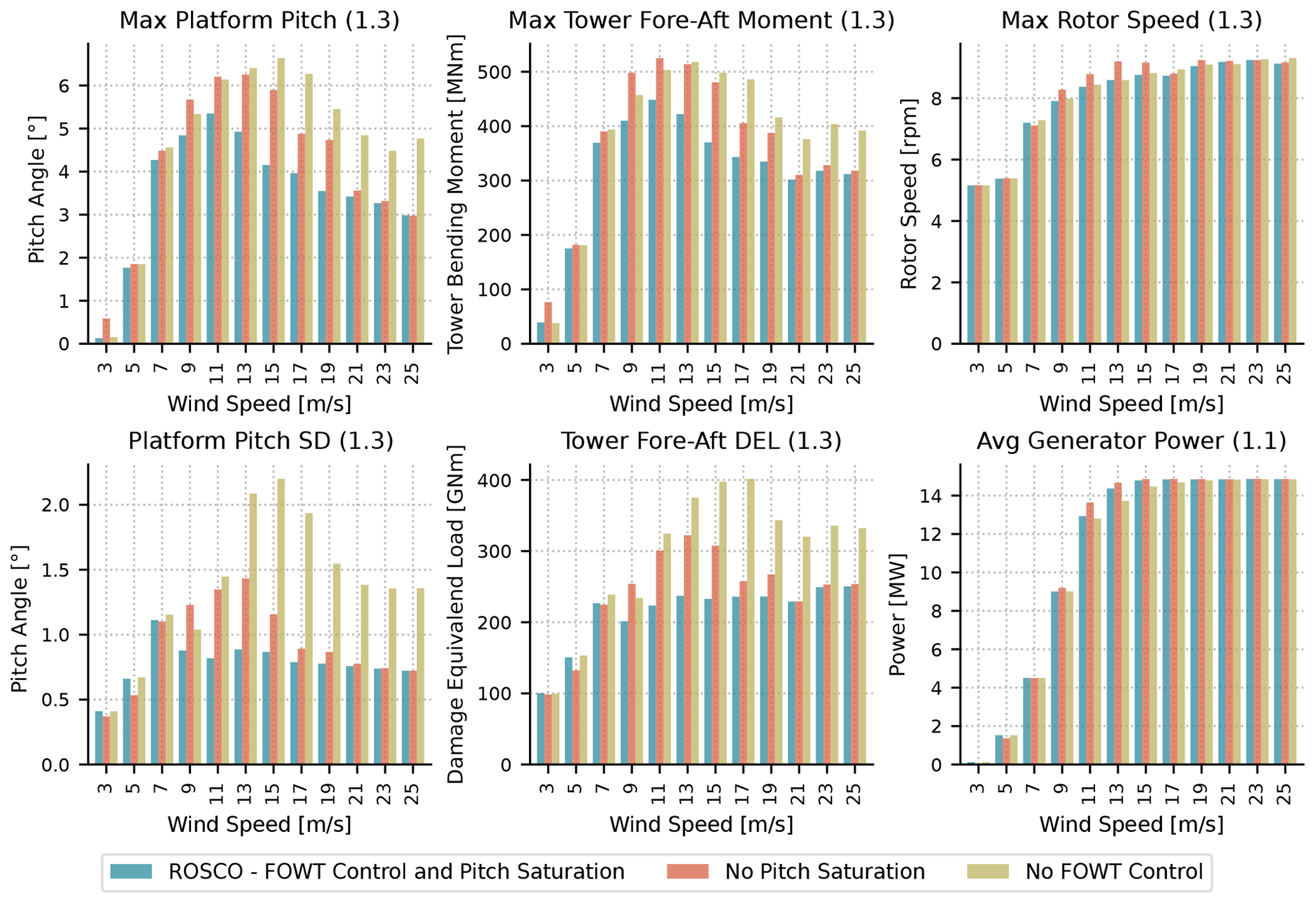
Figure 14Results from DLC 1.1 and 1.3 simulations for the IEA 15 MW wind turbine on the UMaine semisubmersible platform. Output statistics from the platform pitch angles, tower base fore–aft bending moments, rotor speed, and generator power are shown. Simulations using the FOWT feedback loop (βfloat) and pitch saturation (at low wind speeds and for peak shaving) are compared to those with the pitch saturation or FOWT feedback modules turned off.
Figure 14 presents results from the DLC 1.1 and 1.3 simulations. With the peak shaving enabled, slight decreases in power production are seen at near-rated wind speeds. This does, however, correlate to significant reductions of tower fore–aft bending moments and related loads near rated. The presented reduction in platform pitching motion of about 15 % resulting from the floating-specific feedback term has a clear effect on the tower base bending moment as well. The above-rated maximum rotor speed is not expected to change significantly with and without the peak shaving and floating controller because the standard pitch controller for rotor speed regulation is the same. Similarly, the average power output is expected to drop when peak shaving is introduced, as shown in the bottom right plot of Fig. 14.
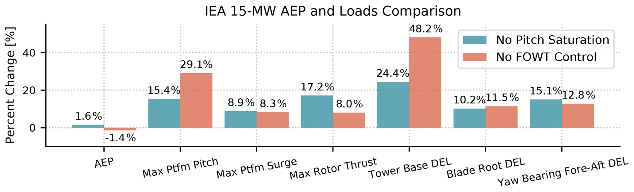
Figure 15An AEP and load comparison of the IEA 15 MW wind turbine on the UMaine semisubmersible platform. The presented values show the percent change of the metrics identified along the x axis with respect to the ROSCO controller with FOWT tuning and pitch saturation (at low wind speeds and for peak shaving) routines enabled. The AEP and DELs were calculated using DLC 1.1 results, and the maximum deflections were calculated using results from DLC 1.3.
Figure 15 shows a comparison of the three presented iterations of the ROSCO controller for the IEA 15 MW wind turbine on the UMaine semisubmersible platform. In Fig. 15, ROSCO with FOWT tuning, low wind-speed pitch saturation, and peak shaving is used as the baseline. For a number of metrics of interest, the percent difference when using ROSCO without any pitch saturation and without the FOWT feedback term is shown. As expected, by removing the pitch saturation term, the annual energy production (AEP) increases by 1.6 %. This is directly related to the reduced power output in low wind speeds because there is not power-maximizing pitch saturation and in near-rated wind speeds where the thrust is being reduced. When the pitch saturation module is kept on and the floating feedback term is removed, the AEP decreases by 1.4 %. This suggests that the increased platform damping that results from the floating feedback term also helps increase AEP. Overall, maximum platform deflections and tower damage equivalent loads are also seen to decrease somewhat significantly throughout the turbine, with both peak shaving and the floating feedback term enabled, while AEP is not detrimentally affected. In this work, no specific tuning of the floating feedback term or blade pitch controller gains was done outside of the methods presented in Sects. 5.5 and 2.5, so overall controller performance could certainly be tuned and improved.
We have provided the research community with a reference open-source controller (ROSCO) for fixed and floating offshore wind turbines. Generic tuning methods have been developed for the ROSCO controller and made available through the Python-based ROSCO toolbox. The tuning methods can be implemented easily by the interested non-controls engineer or in a completely automated fashion for use in optimization routines.
On the NREL 5 MW land-based wind turbine, we have shown that the generically tuned ROSCO controller performs comparably to the NREL 5 MW reference controller. We have also shown that, through a small amount of additional controller tuning, ROSCO's performance can be further improved to reduce rotor thrusts without significant reductions in power generation. We have also provided the foundations of more modern, industry standard control methods, such as peak shaving and wind speed estimation. A TSR tracking controller is shown to generate below-rated turbine power outputs that are consistent with the expectation based on the literature without significant power fluctuation or increased tower-base loads. No significant differences have been made to the implementation of the above-rated collective blade pitch controller, but automated tuning methods have been developed to easily generate pitch-dependent gain schedules for the blade pitch controller based on the Cp surface. A set point smoother has been implemented to improve the transition between the primary blade pitch and generator torque controller regions. A Kalman filter-based wind speed estimator is implemented in ROSCO to enable the TSR tracking and blade pitch saturation capabilities. Pitch saturation routines have been implemented to improve power output in low wind speeds and reduce rotor thrust rated wind speeds. A simple shutdown logic has also been implemented to facilitate more realistic wind turbine testing for the IEC DLCs.
Additionally, a FOWT-specific feedback loop is included in ROSCO and has shown improvements over previously published open-source FOWT control methods. The combination of a FOWT-specific feedback loop and a peak shaving routine has been shown to significantly reduce platform pitch motions and maximum rotor speeds compared to a simple pitch controller with a bandwidth below the first fore–aft natural frequency of the platform. Notably, all the results shown for the IEA 15 MW on the UMaine semisubmersible are shown for the generalized ROSCO tuning values, and there is potential to further improve controller performance through additional fine-tuning of the input parameters to the ROSCO toolbox.
Several other capabilities are also being incorporated in ROSCO and the ROSCO toolbox generic tuning logic. These capabilities and tuning methods are currently being developed, some of which include individual pitch control, distributed aerodynamic control, and improved FOWT feedback term tuning methods. A number of specific improvements for the control methods discussed in this paper will also be implemented. These include additional functionalities for the blade pitch and torque controller, such as power-reference tracking control and tower resonance avoidance methods. Improved shutdown and yaw methods are also being actively investigated.
Finally, the authors would like to reiterate that ROSCO and the ROSCO toolbox are open-source tools. We invite the research community to download, use, and contribute to these codes in whichever ways they see fit.
Four filters are used in the ROSCO controller. For the filters presented, ωf is a cornering frequency in rad s−1, and ζf is a unitless damping ratio.
First-order low-pass filter
Second-order low-pass filter
First-order high-pass filter
Notch filter
The ROSCO controller and toolbox are available for download at https://github.com/NREL/ROSCO (NREL, 2021; https://doi.org/10.5281/zenodo.5748043, nikhar-abbas et al., 2021).
The data presented in work can be made available upon request.
NA developed the generic tuning processes, formalized the control concepts, and collected the theoretical foundations discussed in this article. He also contributed the majority of the code found in ROSCO and the ROSCO toolbox and established them as the tools that they are today. NA was also the primary contributor to the writing of the article. DZ contributed to much of the testing and verification of the ROSCO toolchain. He has also served in an advisory role during the development of many of ROSCO's modules and reviewed this article multiple times before its submittal. AW contributed the original theoretical idea behind the tuning of the floating feedback term, served in an advisory role, and reviewed this article multiple times. LP served in a supervisory role, guided the theoretical foundations discussed in this article, and reviewed this article extensively.
The contact author has declared that neither they nor their co-authors have any competing interests.
This work was authored in part by the National Renewable Energy Laboratory, operated by Alliance for Sustainable Energy, LLC, for the US Department of Energy (DOE) under contract no. DE-AC36-08GO28308. Funding was provided by the US Department of Energy Office of Energy Efficiency and Wind Energy Technologies Office. The views expressed in the article do not necessarily represent the views of the DOE or the US Government. The US Government retains and the publisher, by accepting the article for publication, acknowledges that the US Government retains a nonexclusive, paid-up, irrevocable, worldwide license to publish or reproduce the published form of this work, or allow others to do so, for US Government purposes.
Publisher’s note: Copernicus Publications remains neutral with regard to jurisdictional claims in published maps and institutional affiliations.
The authors specifically thank Jan-Willem van Wingerden and Sebastiaan Mulders from the Delft University of Technology for their contributions to the Delft Research Controller, which provided much of the foundations upon which the ROSCO controller has been built.
Additionally, we thank the many researchers at the National Renewable Energy Laboratory, who have put the entire ROSCO toolchain through its paces in numerous applications. In particular, the authors thank Pietro Bortolotti and Evan Gaertner (now at Siemens Gamesa), who helped ROSCO through perhaps the most challenging software bugs. A special thanks to Paul Fleming as well for his initial inspiration on the structure of the ROSCO toolbox.
This research has been supported by the US Department of Energy, Office of Energy Efficiency and Renewable Energy (grant no. DE-AC36-08GO28308) and the US Department of Energy, Advanced Research Projects Agency – Energy (grant no. DE-AR0000ABC).
This paper was edited by Michael Muskulus and reviewed by Turaj Ashuri and two anonymous referees.
Abbas, N. J., Wright, A., and Pao, L.: An Update to the National Renewable Energy Laboratory Baseline Wind Turbine Controller, J. Phys. Conf. Ser., 1452, 012002, 2020. a
Allen, C., Viselli, A., Dagher, H., Goupee, A., Gaertner, E., Abbas, N., Hall, M., and Barter, G.: Definition of the UMaine VolturnUS-S Reference Platform Developed for the IEA Wind 15-Megawatt Offshore Reference Wind Turbine, Tech. rep., International Energy Agency, https://www.nrel.gov/docs/fy20osti/76773.pdf (last access: 1 December 2021), 2020. a
Bak, C., Zahle, F., Bitsche, R., Kim, T., Yde, A., Henriksen, L. C., Natarajan, A., and Hansen, M.: Description of the DTU 10 MW reference wind turbine, Tech. Rep. I-0092, Technical University of Denmark, Department of Wind Energy, 2013. a
Ben-Kiki, O., Evans, C., and Ingerson, B.: YAML ain't markup language (yaml™) version 1.1, Working Draft 2008-05, 11, [code], 2009. a
Bossanyi, E.: Wind turbine control for load reduction, Wind Energy, 6, 229–244, 2003. a
Bossanyi, E. A.: The design of closed loop controllers for wind turbines, Wind Energy, 3, 149–163, 2000. a, b, c
Bottasso, C. and Croce, A.: Power curve tracking with tip speed constraint using LQR regulators, Scientific Report DIA-SR, 09–04, 2009. a
Bottasso, C. L., Campagnolo, F., and Croce, A.: Multi-disciplinary constrained optimization of wind turbines, Multibody Syst. Dyn., 27, 21–53, 2012. a
Bottasso, C. L., Croce, A., and Riboldi, C.: Optimal shutdown management, J. Phys. Conf. Ser., 524, 012050, 2014. a
Burton, T., Jenkins, N., Sharpe, D., and Bossanyi, E.: Wind energy handbook, John Wiley & Sons, West Sussex, England, 2011. a
DNV-GL: Bladed, [code], https://www.dnvgl.com/energy (last access: 1 December 2021), 2018. a, b
Dykes, K., Ning, A., King, R., Graf, P., Scott, G., and Veers, P. S.: Sensitivity analysis of wind plant performance to key turbine design parameters: a systems engineering approach, in: 32nd ASME Wind Energy Symposium, National Harbor, Maryland, 13–17 January 2014, AIAA 2014-1087 p. 1087, 2014. a
Fischer, B. and Shan, M.: A survey on control methods for the mitigation of tower loads, Fraunhofer IWES Report, 2013. a
Fleming, P. A., Pineda, I., Rossetti, M., Wright, A. D., and Arora, D.: Evaluating methods for control of an offshore floating turbine, in: ASME 2014 33rd International Conference on Ocean, Offshore and Arctic Engineering, American Society of Mechanical Engineers Digital Collection, San Francisco, California, USA, 8–13 June2014, OMAE2014-24107, 2014. a, b
Fleming, P. A., Peiffer, A., and Schlipf, D.: Wind turbine controller to mitigate structural loads on a floating wind turbine platform, J. Offshore Mech. Arct., 141, OMAE-16-1097, https://doi.org/10.1115/1.4042938, 2016. a
Franklin, G. F., Powell, J. D., and Emami-Naeini, A.: Feedback control of dynamic systems, 8 edn., Pearson, New York, NY, 2019. a
Gaertner, E., Rinker, J., Sethuraman, L., Zahle, F., Anderson, B., Barter, G. E., Abbas, N. J., Meng, F., Bortolotti, P., Skrzypinski, W., Scott, G. N., Feil, R., Bredmose, H., Dykes, K., Shields, M., Allen, C., and Viselli, A.: IEA Wind TCP Task 37: Definition of the IEA 15-Megawatt Offshore Reference Wind Turbine, Tech. rep., National Renewable Energy Laboratory, Golden, CO, USA, 2020. a, b, c
Garcia-Sanz, M.: Control Co-Design: an engineering game changer, Advanced Control for Applications: Engineering and Industrial Systems, 1, e18, 2019. a
Grewal, M. S. and Andrews, A. P.: Kalman filtering: Theory and Practice with MATLAB, John Wiley & Sons, New York, NY, 2014. a
Griffith, D. T. and Ashwill, T. D.: The Sandia 100 m all-glass baseline wind turbine blade: SNL100-00, Sandia National Laboratories Technical Report, SAND2011-3779, 2011. a
Hansen, M. H. and Henriksen, L. C.: Basic DTU Wind Energy Controller, Tech. Rep. E-0028, Technical University of Denmark, Department of Wind Energy, 2013. a, b
Holley, W., Rock, S., and Chaney, K.: Control of variable speed wind turbines below-rated wind speed, in: Proceedings of the 3rd ASME/JSME Joint Fluids Engineering Conference, The American Society of Mechanical Engineers, New York, 18 July 1999, 1999. a
IEA Wind Task 37: IEA-15-240-RWT, GitHub [code], https://github.com/IEAWindTask37/IEA-15-240-RWT, last access: 1 December 2021. a
IEC: Wind energy generation systems – Part 1: Design requirements, IEC 614001-1, 4th edn., Internation Energy Commission, Geneva, Switzerland, 2019. a, b, c
Johnson, K. E., Pao, L. Y., Balas, M. J., and Fingersh, L. J.: Control of variable-speed wind turbines: standard and adaptive techniques for maximizing energy capture, IEEE Contr. Syst. Mag., 26, 70–81, 2006. a
Jonkman, J.: Definition of the Floating System for Phase IV of OC3, Tech. rep., National Renewable Energy Laboratory, Golden, CO, USA, 2010. a, b
Jonkman, J., Butterfield, S., Musial, W., and Scott, G.: Definition of a 5-MW reference wind turbine for offshore system development, Tech. rep., National Renewable Energy Laboratory, Golden, CO, USA, 2009. a, b, c, d
Knudsen, T., Bak, T., and Soltani, M.: Prediction models for wind speed at turbine locations in a wind farm, Wind Energy, 14, 877–894, 2011. a, b
Lackner, M. A. and van Kuik, G.: A comparison of smart rotor control approaches using trailing edge flaps and individual pitch control, Wind Energy, 13, 117–134, 2010. a
Larsen, T. J. and Hanson, T. D.: A method to avoid negative damped low frequent tower vibrations for a floating, pitch controlled wind turbine, J. Phys. Conf. Ser., 75, 012073, 2007. a, b, c
MATLAB: version 9.6.0 (R2019a), The MathWorks Inc., Natick, Massachusetts, 2019. a
Mulders, S. and van Wingerden, J.: Delft Research Controller: an open-source and community-driven wind turbine baseline controller, J. Phys. Conf. Ser., 1037, 032009, 2018. a, b, c, d
nikhar-abbas, dzalkind, Mudafort, R. M., Mulders, S., davidheff, Hylander, G., and Bortolotti, P.: NREL/ROSCO: Zenodo Integration (v2.4.1-z), Zenodo [code], https://doi.org/10.5281/zenodo.5748043, 2021. a
Ning, S.: CCBlade Documentation: Release 1.1.0, Tech. rep., National Renewable Energy Laboratory, Golden, CO, USA, 2013. a
NREL: OpenFAST, Version 2.1.0, GitHub [code], https://github.com/openfast/openfast (last access: 1 December 2021), 2019. a
NREL: ROSCO, Version 2.4.1, GitHub [code], https://github.com/NREL/ROSCO (last access: 1 December 2021), 2021. a, b
Pao, L. Y. and Johnson, K. E.: Control of wind turbines, IEEE Contr. Syst. Mag., 31, 44–62, 2011. a
Petrović, V. and Bottasso, C. L.: Wind turbine envelope protection control over the full wind speed range, Renew. Energy, 111, 836–848, 2017. a
Robertson, A., Jonkman, J., Masciola, M., Song, H., Goupee, A., Coulling, A., and Luan, C.: Definition of the semisubmersible floating system for phase II of OC4, Tech. rep., National Renewable Energy Laboratory, Golden, CO, USA, 2014. a
Sathe, A., Mann, J., Barlas, T., Bierbooms, W., and Van Bussel, G.: Influence of atmospheric stability on wind turbine loads, Wind Energy, 16, 1013–1032, 2013. a
Schlipf, D.: Set-Point-Fading for Wind Turbine Control, Zenodo, https://doi.org/10.5281/zenodo.5567358, 2019. a
Schlipf, D., Schlipf, D. J., and Kühn, M.: Nonlinear model predictive control of wind turbines using LIDAR, Wind Energy, 16, 1107–1129, 2013. a
Van Der Veen, G., Couchman, I. J., and Bowyer, R.: Control of floating wind turbines, in: Proc. 2012 American Control Conference, Montreal, QC, Canada, 27–29 June 2012, https://doi.org/10.1109/ACC.2012.6315120, 3148–3153, 2012. a
Veers, P., Dykes, K., Lantz, E., Barth, S., Bottasso, C. L., Carlson, O., Clifton, A., Green, J., Green, P., Holttinen, H., Laird, D., Lehtomäki, V., Lundquist, J. K., Manwell, J., Marquis, M., Meneveau, C., Moriarty, P., Munduate, X., Muskulus, M., Naughton, J., Pao, L., Paquette, J., Peinke, J., Robertson, A., Sanz Rodrigo, J., Sempreviva, A. M., Smith, J. C., Tuohy, A., and Wiser, R.: Grand challenges in the science of wind energy, Science, 366, eaau2027, https://doi.org/10.1126/science.aau2027, 2019. a
Wayman, E. N., Sclavounos, P., Butterfield, S., Jonkman, J., and Musial, W.: Coupled dynamic modeling of floating wind turbine systems, Tech. rep., National Renewable Energy Laboratory, Golden, CO, USA, 2006. a
Zahle, F., Tibaldi, C., Verelst, D. R., Bak, C., Bitche, R., and Blasques, J. P. A. A.: Aero-elastic optimization of a 10 MW wind turbine, in: 33rd Wind Energy Symposium, Kissimmee, Florida, 5–9 January 2015, AIAA 2015-0491 p. 0491, 2015. a
Zalkind, D. S. and Pao, L. Y.: Constrained Wind Turbine Power Control, in: Proc. 2019 American Control Conference, Philadelphia, PA, USA, 10–12 July 2019, https://doi.org/10.23919/ACC.2019.8814860, 3494–3499, 2019. a
Zalkind, D. S., Dall'Anese, E., and Pao, L. Y.: Automatic controller tuning using a zeroth-order optimization algorithm, Wind Energ. Sci., 5, 1579–1600, https://doi.org/10.5194/wes-5-1579-2020, 2020. a
- Abstract
- Introduction
- Foundations of the Reference Open-Source Controller
- The generator torque controller
- The blade pitch controller
- Additional control modules
- Example results and analysis
- Conclusions and future work
- Appendix A: Filters
- Code availability
- Data availability
- Author contributions
- Competing interests
- Disclaimer
- Acknowledgements
- Financial support
- Review statement
- References