the Creative Commons Attribution 4.0 License.
the Creative Commons Attribution 4.0 License.
 | 26 Jun 2024
Assessing the impact of waves and platform dynamics on floating wind-turbine energy production
Alessandro Fontanella
Giorgio Colpani
Marco De Pascali
Sara Muggiasca
Marco Belloli
Waves have the potential to increase the power output of a floating wind turbine by forcing its rotor to move against the wind. Starting from this observation, we use four multi-physics models of increasing complexity to investigate the role of waves and platform movements in the energy conversion process of four floating wind turbines of 5–15 MW in the Mediterranean Sea. Progressively adding realism to our simulations, we show that large along-wind rotor movements are needed to increase the power output of a floating wind turbine; however, these are prevented by the current technology of spar and semi-submersible platforms. Wind turbulence is the main cause of power fluctuations for the four floating wind turbines we examined and is preponderant over the effect of platform motions due to waves. In a realistic met-ocean environment, the power curve of the floating wind turbines we studied is lower than that obtained with a fixed foundation, with reductions in the annual energy production of 1.5 %–2.5 %. The lower energy production is mainly ascribed to the platform mean tilt, which reduces the rotor's effective area.
- Article
(12285 KB) - Full-text XML
- BibTeX
- EndNote


Floating offshore wind turbines (FOWTs) have high energy generation potential for deep waters. Compared to their bottom-fixed counterparts, they can be installed in more sea areas and further away from the coast, where the wind generally blows stronger. This also reduces the visual impact from shore and interferes less with other users of the marine space. At the time of writing, the cost of energy produced by floating wind turbines is still high, but in the coming decades, it is expected to drop to the same level as other wind technologies (Wiser et al., 2021).
One reason for the higher cost is that the advantages of floating wind turbines are balanced out by their higher system complexity compared to bottom-fixed solutions. The primary dissimilarity between the two technologies is the compliance of the floating foundation, which allows large-amplitude, low-frequency motions of the structure. Due to these motions, the rotor of a floating wind turbine may operate differently than when the tower is fixed to the seabed, and it is reasonable to expect that this has some effects on power production.
From an energy point of view, the waves driving the floater motion introduce additional energy into the wind turbine, which can potentially increase its power generation. Finding ways to exploit wave energy in floating wind turbines has been identified as one research challenge for the wind energy community (van Kuik et al., 2016). There are only a few articles on studies of the impact of waves and platform dynamics on the power production of a floating wind turbine. Martini et al. (2016) investigated the effect of the met-ocean conditions on tower inclination and hub acceleration and their possible consequences for shutdowns and the capacity factor. The effect of platform motion on the energy conversion process has recently been addressed by Amaral et al. (2022) and Cottura et al. (2022), but both used simplifications, such as prescribed (or imposed) sinusoidal movement of the platform in one direction and steady wind, that make their findings difficult to apply to a real scenario.
Knowledge of the influence of waves and platform dynamics on wind turbine energy production complements the results of studies about the effect of wind and atmospheric conditions on the power output of land-based wind turbines. Among these, Clifton et al. (2014) discussed the impact of wind parameters on the performance of a wind turbine installed in a mountain pass with complex inflows, and St. Martin et al. (2016) explored the sensitivity to atmospheric conditions of the power curve and the annual energy production of a 1.5 MW wind turbine.
The fundamental question this article wants to answer is how the peculiar dynamics of floating foundations and wave excitation impact the energy production of a floating wind turbine. When answering this question, we examine four realistic wind turbine concepts with ratings of 5–15 MW and spar and semi-submersible platforms, and we consider the environmental conditions of an area in the Mediterranean Sea that is suitable for the development of floating wind projects. Four multi-physics models of increasing complexity are used to clarify how the physics of the energy conversion process taking place at the rotor of a floating wind turbine is influenced by platform motions and waves. The main contribution of this paper is to show that, according to simplified modeling, a rotor forced to move against the wind can have higher average power than when the rotor is stationary. However, this increase in power is not obtained under normal operating conditions if a realistic description of platform movements and the response to wave excitation is considered.
The results and the methodology of this work can be used in the early stages of floating wind projects to quantify their energy production and reduce investment risk. Better knowledge of the energy conversion process can help optimize the turbine design for the operating conditions expected in a given sea area, thus lowering the cost of turbines.
The structure of the article is as follows. Section 2 presents the four floating wind-turbine concepts analyzed in this study, the numerical tools we used to estimate their energy production, the met-ocean conditions considered in the analysis, and the four simulation models. Section 3 reports the results of numerical simulations clarifying the influence of wind turbine control, platform compliance, dynamic platform motion, and stochastic wind and waves on the power production of the four floating wind turbines. The article concludes with Sect. 4, which explains possible uses of the results obtained in this paper and reports some suggestions for future work.
A mathematical model is useful to understand the effect of platform motion on the energy production of a floating wind turbine. The model greatly simplifies the response of a floating wind-turbine rotor, which is schematized as a point coincident with the wind turbine hub that moves longitudinally in the wind direction. This model is often used in studies about the aerodynamic response of floating wind turbines, such as the recent works by Fontanella et al. (2022) and Cioni et al. (2023). The aerodynamic power of the rotor is
where ρ is the air density, R the rotor radius, V the wind speed at the rotor, and CP the power coefficient. Assuming that the hub undergoes harmonic motion, we can replace the wind speed V with the apparent wind speed Vr, which is influenced by the movement of the rotor against the wind. If the wind field is uniform and steady,
where U is the mean wind speed, ωm is the motion's circular frequency, and Am,h is the amplitude of the hub motion in the wind direction. The amplitude of the apparent wind speed seen by the hub is Ur,h=ωmAm,h. Substituting Eq. (2) into Eq. (1) gives
Consider the four terms inside the parentheses on the left-hand side of Eq. (3). We see that U3 is constant over time. 3U2Ur,hcos (ωmt) has a null integral over one period of motion, and the same is true for (Ur,hcos (ωmt))3 but not for 3U(Ur,hcos (ωmt))2. The mean value of the rotor power over one period of motion is evaluated from Eq. (3) and is
Assuming that CP is constant over time, Eq. (4) shows that in a rotor undergoing harmonic motion in the wind direction, the average power output increases.
However, it is necessary to determine if the increase in power predicted by this simple model translates into higher generated power for a realistic wind turbine when normal operating conditions are considered. In fact, in a floating wind turbine, the rotor's CP is not constant but modified dynamically by the wind turbine controller; the motion of the rotor is not perfectly aligned with the wind, but its direction depends on those of the wind and waves and the characteristics of the platform. Motions in different directions (e.g., surge or pitch) can occur simultaneously; these motions can couple and can display a constructive or destructive interaction depending on their respective phases.
In this work, we assume that the energy production of a floating wind turbine is influenced by
-
wind, described by mean wind speed, mean direction, turbulence intensity, and vertical shear
-
waves, described by elevation, period, and direction
-
floater characteristics, such as restoring loads, mean tilt, and dynamic response to environmental loads
-
the turbine control strategy, which is modified to accommodate the large low-frequency motions permitted by floating foundations and constitutes a key element of difference between floating and bottom-fixed wind turbines (van der Veen et al., 2012).
In order to isolate their effects, we gradually introduce these parameters in the analysis.
2.1 Simulation scenarios and tools
The impact of waves and platform dynamics on power production is studied by carrying out simulations with four multi-physics models of the floating wind turbine and of the wind–wave conditions around it. The four models gradually add complexity to the simple analytical model of Eq. (3) and are shown schematically in Fig. 1. In detail:
-
The prescribed motion model (Harm-M), described in Sect. 2.1.1, extends the results of Eq. (3) using a more accurate representation of the wind turbine and its control system. The rotor's aerodynamic response is calculated with the blade element momentum model rather than with a constant power coefficient, the blades and tower are flexible elements, and the wind turbine is regulated with an active control scheme. The wind turbine is subjected to prescribed harmonic motion in the surge, sway, heave, roll, pitch, and yaw directions; motions are applied separately. In the Harm-M model, wind is steady and uniform. Amaral et al. (2022) and Cottura et al. (2022) used a modeling approach similar to this one to study the effect of platform motion on wind turbine power.
-
The regular-wave model (Harm-W), described in Sect. 2.1.2, introduces the floater's dynamic response to waves into the analysis. The floating wind-turbine response in the Harm-W model is more realistic than that in the Harm-M model since platform motions in different directions can occur simultaneously and interact depending on their phases relative to the waves. Regular-wave simulations are often used in the study of floating wind-turbine response to wave loading as a first step in complexity before considering irregular waves; for example, this was recently done by Mahfouz et al. (2021) and Patryniak et al. (2023) when assessing the coupled motions of FOWTs. Harm-W simulations use a similar approach to link waves, platform motions, and rotor power.
-
The model with simplified wind–wave conditions (Coupled-S), described in Sect. 2.1.3, considers hydrodynamic loading and the floater's dynamic response, but wind and waves are stochastic, and their properties are defined according to the standard industrial practice to reflect the met-ocean conditions of a sea area in the Mediterranean. Wind and waves are aligned to the platform's main axis and excite rotor motion mainly in the along-wind direction, similarly to the model of Eq. (3). Simulations with stochastic wind and waves aligned to each other are often used to identify the response characteristics of FOWTs, as done, for example, by Mahfouz et al. (2021).
-
In the model with clustered wind–wave conditions (Coupled-C), described in Sect. 2.1.4, the environmental parameters of simulations are extracted by means of a clustering algorithm from a database of met-ocean data recorded at the reference site. In Coupled-C simulations, wind and waves are not aligned, but their directionality is representative of the portion of sea of interest. The importance of wind–wave misalignment in the global response of FOWTs has been investigated by Bachynski et al. (2014) and is introduced here in the simulations to assess its influence on power production. In this work, the Coupled-C model provides the most accurate representation of the operating conditions a floating wind turbine would meet if installed in the area we selected.
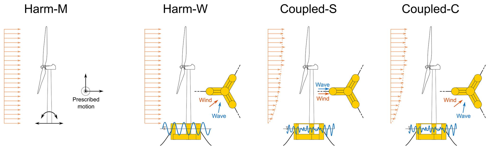
Figure 1The influence of platform motion due to waves on the power production of floating wind turbines is studied with four simulation models. In the Harm-M model, sinusoidal motion of varying amplitude and frequency is prescribed at the base of the wind turbine tower. In the Harm-W model, the turbine is excited with regular waves of different amplitudes, frequencies, and directions. In the Coupled-S and Coupled-C models, the wind turbine response is computed for several environmental conditions with full-field turbulent wind and irregular waves; wind–wave conditions are obtained with simplifications typically used by standards (Coupled-S) or they are extracted by means of clustering from a database of met-ocean data (Coupled-C).
The main assumptions of the four models about wind, waves, and the floating platform are summarized in Table 1.
Table 1Main assumptions of the four models of the floating wind turbine about wind, waves, and the floating platform. Wind and waves are “aligned” when they are directed along the platform's main axis.
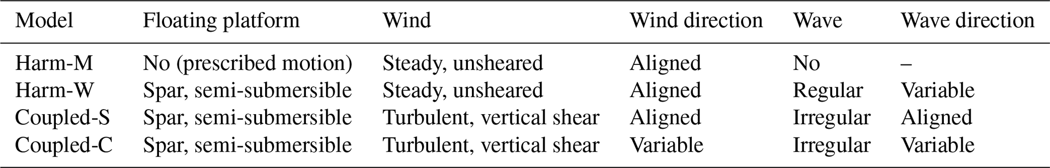
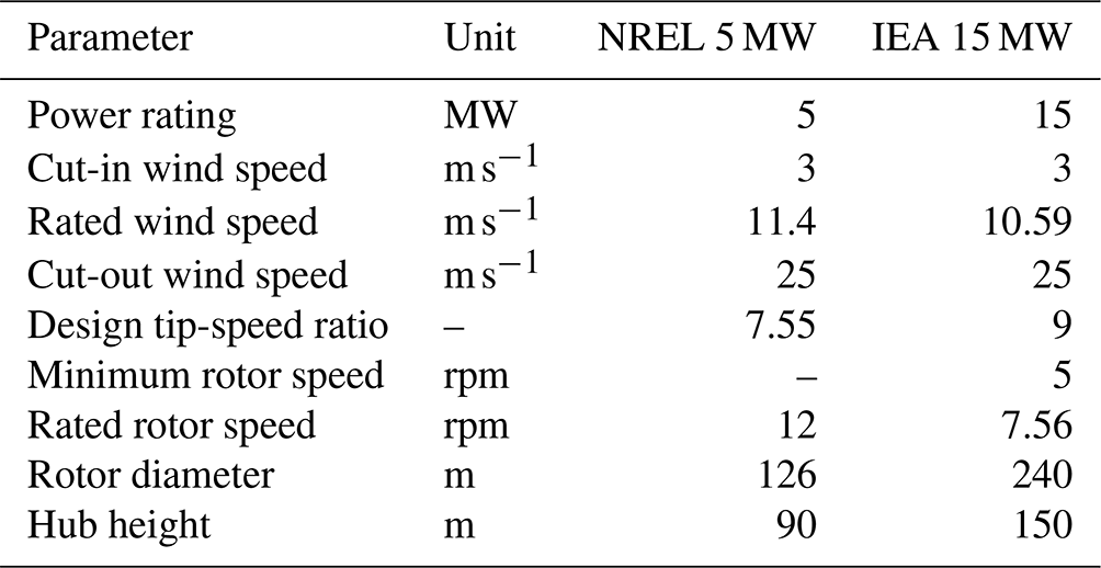
The Harm-W and Coupled-C models consider the wind–wave directionality. The heading directions of the wind and waves (θ and β, respectively) are defined in Fig. 2; the difference between them () is the wind–wave misalignment angle. We assume that the nacelle yaw angle is always consistent with the wind direction.
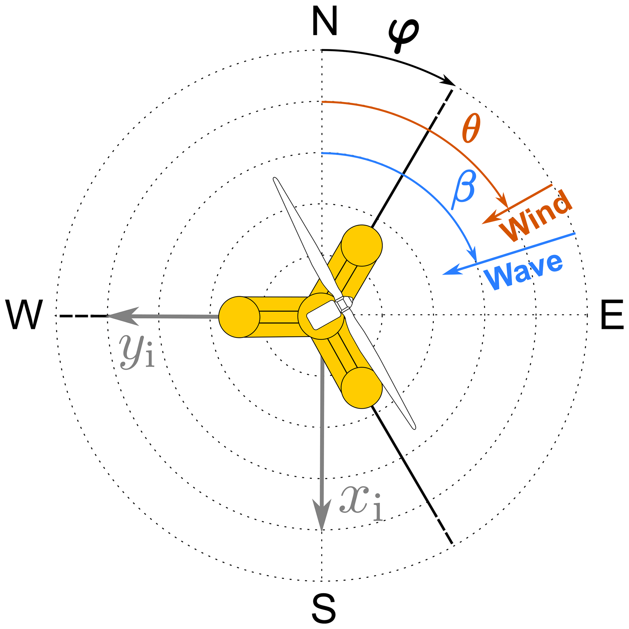
Figure 2Definitions of the platform's mounting orientation (φ), the wind direction (θ), the wave direction (β), and the wind–wave misalignment angle (). xi and yi are the axes of the earth-fixed coordinate system.
All models are built in OpenFAST (Jonkman et al., 2023), which includes modules for aerodynamics, hydrodynamics, control, and structural dynamics. The aerodynamic forces are calculated in AeroDyn v15, based on the quasi-steady blade element momentum theory. The aerodynamic influence of the tower is considered with a potential-flow model, and the blade airfoil aerodynamics are computed using the Beddoes–Leishman approach. The structural response of the system is modeled in ElastoDyn, based on multi-body theory and the modal approach. Hydrodynamic forces are calculated in HydroDyn using a combination of potential-flow theory (to compute radiation and diffraction effects) and strip theory (to model viscous drag); the hydrodynamic coefficients required for the potential-flow solution are obtained with a panel code. The mooring lines are modeled in MoorDyn, which uses a lumped-mass approach to discretize the cable dynamics over the length of the lines (Hall and Goupee, 2015). In the Harm-M model, tower-base motion is prescribed, with the floating platform replaced with a mass–spring–damper system implemented in the SubDyn module (Branlard et al., 2020).
The incoming turbulent wind is introduced into the simulations by means of TurbSim (Jonkman, 2009a), which is a stochastic, full-field, turbulent wind simulator that uses a statistical model to numerically simulate the time series of the three components of the wind velocity vector at specified points on a two-dimensional grid fixed in space.
2.1.1 Simulations with prescribed motion
In simulations with the Harm-M model, platform movement is prescribed at the tower base. It is sinusoidal and applied separately along the six rigid-body motion directions of the turbine foundation; the phase is arbitrarily fixed at zero. The motion frequency (fm) ranges from 0 to 0.3 Hz. This range covers very low frequencies that are typical of rigid-body motion modes of large floating wind turbines (Mahfouz et al., 2021) and extends above the frequency range of typical wave spectra. The motion amplitude (Am) varies from 0 to 3 m in the case of translations and from 0 to 1.25° in the case of rotations. These values are considered realistic for normal operating conditions of floating wind turbines with characteristics similar to those considered in this study. Wind is steady and has no shear: this assumption is unrealistic but enables us to discern more clearly the effect of platform motions on the generated power.
2.1.2 Simulations with regular waves
The Harm-W model introduces into the analysis the dynamic response of the floating wind turbine to incident waves. Each wave is of the regular type and has a variable direction β; the values of wave height are 0.5, 1.0, 1.5, 2.0, 2.5, and 3.0 m; and the values of wave frequency are 0.05, 0.10, 0.15, 0.20, 0.25, and 0.30 Hz. These values are representative of the wave conditions at the reference sea site, as described in Sect. 2.3. Wind is steady and has no shear.
2.1.3 Coupled simulation with simplified wind–wave conditions
The Coupled-S model uses stochastic sheared wind and stochastic waves. The load cases are defined according to the recommendations of IEC 61400-3 (International Electrotechnical Commission, 2019) for fatigue load calculations:
-
Wind and waves are aligned to the symmetry axis of the platform (i.e., with reference to Fig. 2, ).
-
A wind speed interval of 2 m s−1 is considered, starting from 3 m s−1 and ending at 25 m s−1.
-
The wave height is defined from its linear correlation with the average wind speed.
-
Three wave periods are associated with each wave height. Wave periods are obtained from the scatter diagram for the site as the three most probable periods for the selected wave height.
Every load case is simulated for 3 h after an initial pre-simulation time of 3200 s that is introduced to account for transients.
2.1.4 Coupled simulation with clustered wind–wave conditions
Coupled-C simulations reproduce the wind–wave environment of the reference sea site without making use of assumptions about the relations among wind speed, wind direction, wave height, wave period, and wave direction. Instead, the load cases of the simulations are extracted from long-term series of the wind and wave parameters.
Approximately 4 CPU hours are required to simulate one sea state for 3 h in OpenFAST, and it is impractical to simulate a dataset covering several months or years. Thus, the Coupled-C model considers a small subset of conditions that are representative of the long-term sea conditions at the site. The selection procedure is based on the data-clustering technique, which aims to extract features from the original dataset that give a more compact representation of the dataset properties. Data clustering has seen application in wave climate analysis (Camus et al., 2011) and to extrapolate the wind statistics needed to estimate the energy production of wind energy systems (Schelbergen et al., 2020).
Here, the selection of the subset of met-ocean conditions is based on the K-means algorithm (KMA) (Arthur and Vassilvitskii, 2007). The initial database is formed from five-dimensional vectors whose elements are the variables of interest that characterize the wind and wave climate: wind speed (U), wind direction (β), significant wave height (Hs), peak wave period (Tp), and wave direction (θ).
Given the initial database of N five-dimensional vectors with , the KMA identifies M groups of data, each defined by a five-dimensional prototype vk (with ) called the centroid. The clustering procedure starts with a random initialization of the M centroids; at every algorithm iteration, the nearest data to each centroid are identified and the centroid is redefined as the mean of the corresponding data. For example, at step (r+1), the data vector xi is assigned to the group , where is the Euclidean distance, and is the jth centroid at the rth step. Once every data vector is assigned to a group, the centroid is updated as
where nj is the number of elements in the jth group and Cj is the subset of data included in group j. The KMA iteratively moves the centroids, minimizing the overall within-cluster distance until it converges and the data belonging to every group are stabilized. The working principle of the clustering algorithm is showcased in Appendix A using the dataset for the reference sea site in this study, which is presented in Sect. 2.3.
The number of clusters representing the sea states is a trade-off between the computational cost required for the simulation and the error from using a subset of data instead of the entire dataset. Here, the number of clusters is fixed at M=36, which is the same number of conditions considered in the Coupled-S simulations. Every load case is simulated for 3 h after an initial pre-simulation time of 3200 s.
2.2 Floating wind-turbine concepts
The wind turbines of the FOWT concepts are the NREL 5 MW (Jonkman et al., 2009) and the IEA 15 MW (Gaertner et al., 2020), whose key properties are summarized in Table 2.
Table 2Key properties of the NREL 5 MW and IEA 15 MW wind turbines.
The two wind turbines have a conventional variable-speed, variable blade-pitch-to-feather configuration. Power-production operation is controlled with the Reference OpenSource Controller (ROSCO) of Abbas et al. (2022) (version 2.8.0; NREL, 2023b), which is deemed to be representative of controllers adopted in commercial multi-megawatt wind turbines. In ROSCO, two active proportional integral (PI) controllers are implemented for the generator torque and collective blade pitch angle. Saturation limits on rotor speed and blade pitch are used to ensure the wind turbine works within its design limits. ROSCO has two operating regions:
-
Below rated wind speed. Here, the blade pitch is fixed at its design value of 0°, and a PI controller regulates the generator torque to track the design tip-speed ratio (TSR). The IEA 15 MW has a minimum rotor speed constraint of 5 rpm; thus, at low wind speeds, the blade pitch is scheduled based on a wind speed estimate to improve the turbine power output. This functionality is not used in the NREL 5 MW. The estimate of rotor's effective wind speed required by the TSR-tracking controller and the pitch scheduling is provided by an extended Kalman-filter estimator.
-
Above rated wind speed. Generator torque is constant and equal to its rated value, and rotor speed is regulated with a PI controller of the collective blade pitch angle.
The controller settings we adopted are those of the reference OpenFAST models of the four floating wind turbines, and no further tuning was done in this study.
In addition to these baseline control strategies, we used two more advanced ROSCO functionalities:
-
Peak shaving. This algorithm reduces the maximum thrust force reached when the turbine operates in near-rated winds. The peak shaving is implemented by prescribing a minimum blade pitch >0° as a function of the wind speed.
-
Nacelle velocity feedback. In the above rated wind speed, the nacelle fore–aft acceleration is band-pass filtered, integrated, and multiplied by a constant gain which is set with the method suggested by Abbas et al. (2022). The blade pitch command obtained with this algorithm is summed to the output of the PI pitch controller for rotor speed to improve the stability of platform motion.
We avoided using any control algorithm for start-up and shut-down sequences. When wind speed is below the cut-in or above the cut-out, the wind turbine is stopped and does not produce any power. Moreover, there is no control action to regulate the nacelle–yaw angle, which is constant.
We expect that the control strategies we considered will be adopted in future floating wind turbines. The peak shaving is increasingly important for large FOWTs because it lessens the restoring requirements of the floating platform (Renan dos Santos et al., 2022). Traditionally, the instability issues of FOWT controllers have been solved with detuning, i.e., by reducing their bandwidth to below the natural frequency of the platform pitch mode (van der Veen et al., 2012). As the FOWT size increases, the platform's natural frequencies decrease, leading to slower controllers when applying detuning. This is avoided by using nacelle velocity feedback, which improves the power quality while reducing structural loads (Fleming et al., 2019; Vanelli et al., 2022).
The steady-state operating points of the NREL 5 MW and IEA 15 MW with a fixed tower base regulated with the control strategies described above are visualized in Fig. 3.
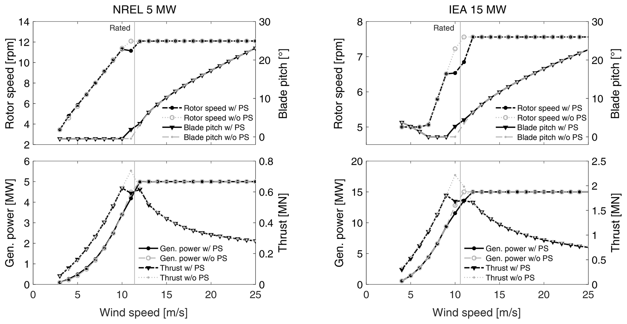
Figure 3Steady-state operating points of the land-based versions of the NREL 5 MW and IEA 15 MW wind turbines. For the sake of comparison, curves without peak shaving (“w/o PS”) are shown together with those obtained with the PS functionality used in the remainder of this work (“w/ PS”).
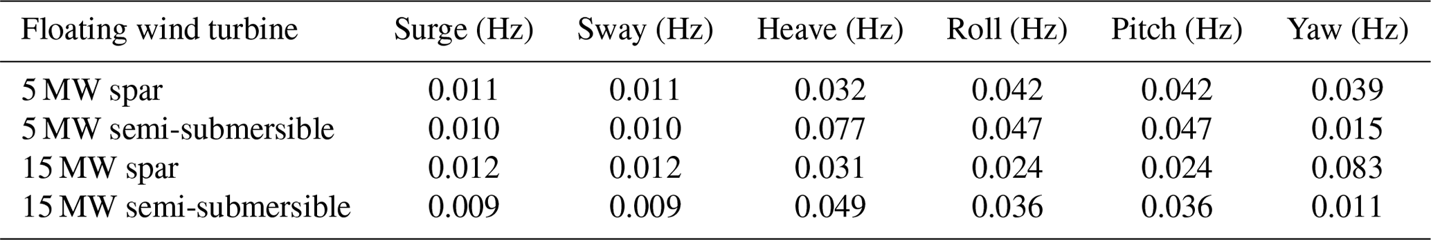
Two platform concepts are examined for each wind turbine: a spar buoy and a semi-submersible. We decided to focus on these substructure typologies because they have been adopted in recent commercial projects and research works. Moreover, there are OpenFAST models for them that are easily accessible in online repositories. Descriptions of the four floating wind turbines are reported in Sects. 2.2.1–2.2.4. The natural frequencies of the rigid-body motion modes of the four floating wind turbines that have been characterized with free-decay no-wind simulations carried out with their OpenFAST models are reported in Table 3.
Table 3Natural frequencies of the rigid-body motion modes of the four floating wind turbines.
2.2.1 OC3 5 MW spar
The OC3-Hywind spar buoy is a floater designed for the NREL 5 MW reference wind turbine (Jonkman, 2009b). The floater is made of steel. It is ballasted with inert material and composed of a 120 m draft cylinder that tapers from 9.4 m in diameter to 6.5 m in diameter in correspondence to the sea surface. The linearly tapered conical region extends from a depth of 4 m to a depth of 12 m below the mean sea level; the overall length of the floater is 130 m. The design water depth for the floater is 320 m. The mooring system consists of three all-chain slack catenaries spread 120° apart. Each line has an unstretched length of 902.2 m and a diameter of 0.09 m, and delta lines connecting mooring lines to fairleads are used to increase yaw stiffness.
2.2.2 DeepCwind 5 MW semi-submersible
The OC4 DeepCwind semi-submersible is a floater design developed in the DeepCwind project (Robertson et al., 2014). The platform consists of a main column supporting the wind turbine tower and three offset columns connected to the main one through a series of smaller diameter pontoons and cross members; the draft is 20 m. The floater is moored with three catenary lines spread symmetrically about the vertical axis. The fairleads are positioned at a depth of 14.0 m below the water level and at a radius of 40.87 m from the platform centerline, while the anchors are located at a water depth of 200 m and at a radius of 837.6 m from the platform centerline.
2.2.3 WindCrete 15 MW spar
The WindCrete, introduced by Campos et al. (2016), is a spar-type platform supporting the IEA 15 MW. The tower and the spar form a monolithic structure made of concrete. The spar has a diameter of 18.6 m and a draft of 155 m and has ballast in its lower section to increase the hydrostatic stiffness in the roll and pitch directions. The tower has conical shape and, in the version of Campos et al. (2016), places the hub 135 m above the mean sea level. We increased the tower base height from 15 to 30 m while keeping the same flexible tower length to get the same hub height of 150 m as the VolturnUS. Due to this change, the first fore–aft natural frequency is 0.57 Hz instead of 0.5 Hz (the value for the original tower). The mooring system consists of three catenary lines attached to the platform hull with delta-shaped connections. The global response of the WindCrete to several wind and wave conditions was examined by Mahfouz et al. (2021), and the OpenFAST model of the platform is published in the repository of Molins et al. (2020).
2.2.4 VolturnUS 15 MW semi-submersible
The UMaine (University of Maine) VolturnuUS-S (Allen et al., 2020) is an open-source concept for a semi-submersible floating wind turbine based on the IEA 15 MW. The floater is made of steel and is composed of three 12.5 m diameter columns disposed symmetrically around a central column hosting the wind turbine. The three bottom pontoons connecting the inner and outer columns have a rectangular section (12.5 m × 7.0 m) and three cylindrical struts connect the top of the outer column to the central one. The operational draft of the floater is 20 m; the total mass of the platform is 17 854 t. The mooring system is designed for a generic 200 m depth location and is composed of three 850 m long chain catenary lines arranged at 120° angles around the floater. The fairlead is located at the extreme point of each external column, at a radius of 58 m from the vertical axis of the floater and 14 m below the sea water level. The OpenFAST model of the VolturnUS is available from Allen et al. (2023).
2.3 Reference sea-site and met-ocean conditions
The wind and wave conditions defining the load cases are representative of the climate at a sea area sited in the Gulf of Fos, located off the French coast in the Mediterranean Sea. The reference site is shown in Fig. 4; it is 40 km offshore Fos-sur-Mer, and its approximate location is identified by the coordinates N (latitude), E (longitude).
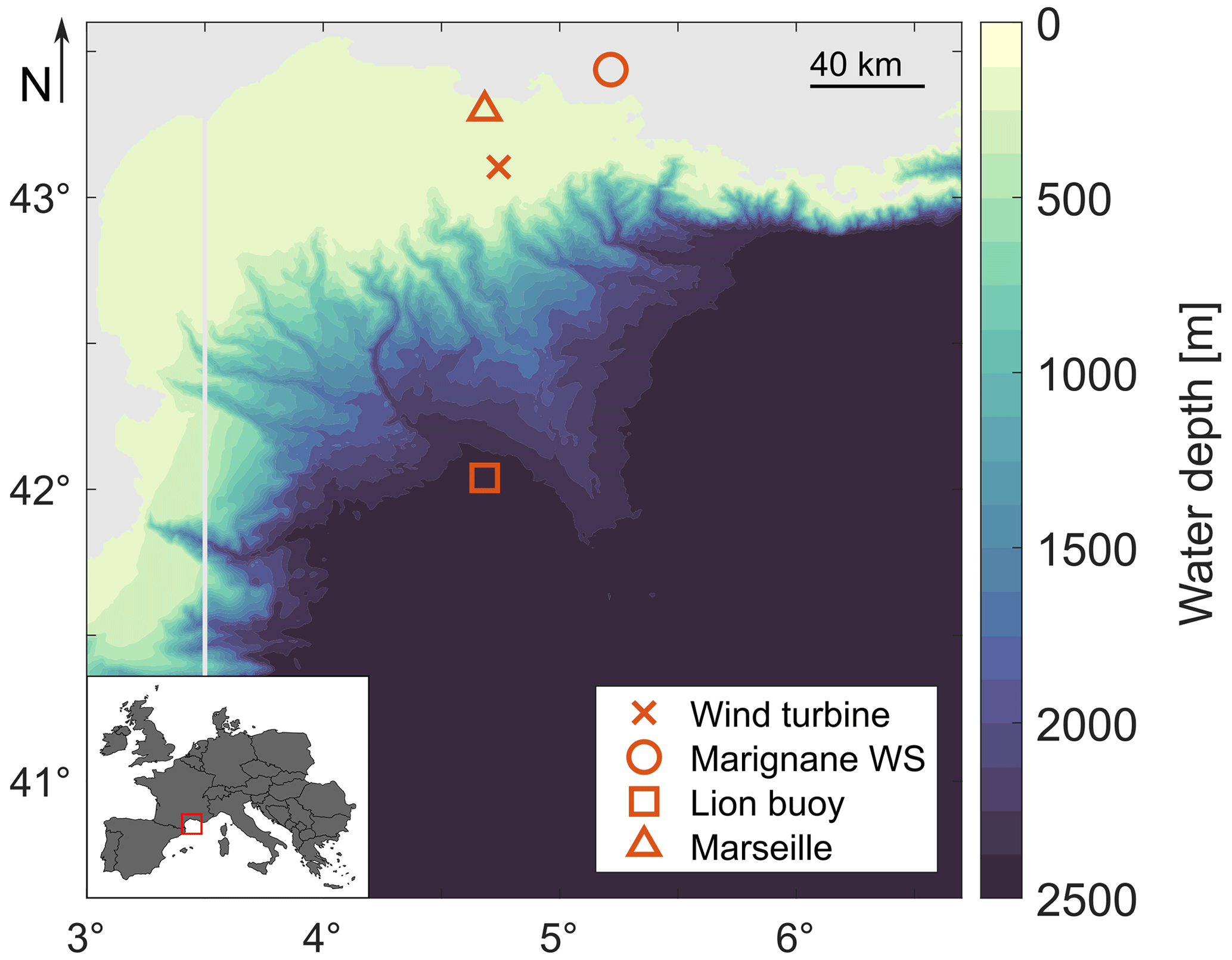
Figure 4Sea area of the reference site of this study. The area is located in the Mediterranean Sea off the French coast, as shown in the inset map. Markers show the positions of the floating wind turbine, Marignane Weather Station (WS), Lion buoy, and the city of Marseille. Land is depicted in gray, and the color scale corresponds to the water depth (EMODnet, 2023).
Two open-access databases have been used to characterize the wind and wave conditions at this site: wind data from Marignane Weather Station, provided by Meteostat (Meteostat, 2022); and wave data from the Gulf of Lion buoy located 100 km south of the site location, shared by MetoFrance (France, 2022). The variables in the dataset of interest for this study are the wind speed at 10 m height, wind direction, wave elevation, wave period, and wave direction. The two databases contain wind–wave measurements for several years; however, wave directionality measurements are only available for the period of 6 months from October 2019 to March 2019. The time resolution is 1 h and the dataset with simultaneous information about the five variables of interest has 3362 data points in total.
No information about the vertical profile of mean wind speed is available, so it is assumed to follow the power law
where U is the mean wind speed, z is a generic height, h is the reference height of 10 m, and α is the shear exponent. In accordance with the meteorological study of Krieger et al. (2015), we take α=0.14.
The wind speed distribution is essential for evaluating the wind turbine's annual energy production. Figure 5 shows the probability density function of the 1 h mean wind speed extrapolated to 150 m height (i.e., the hub height of the IEA 15 MW) by means of Eq. (6). The best-fitting Weibull distribution has a scale parameter of 7.17 and a shape parameter of 1.38. The probability of wind speed occurrence is overpredicted for some bins (e.g., 5–6 m s−1 and 8–9 m s−1), and this problem is likely due to the small size of the database. The best-fitting Weibull distribution for the 1 h mean wind speed at the hub height of the NREL 5 MW (90 m) has a scale parameter of 6.68 and a shape parameter of 1.38.
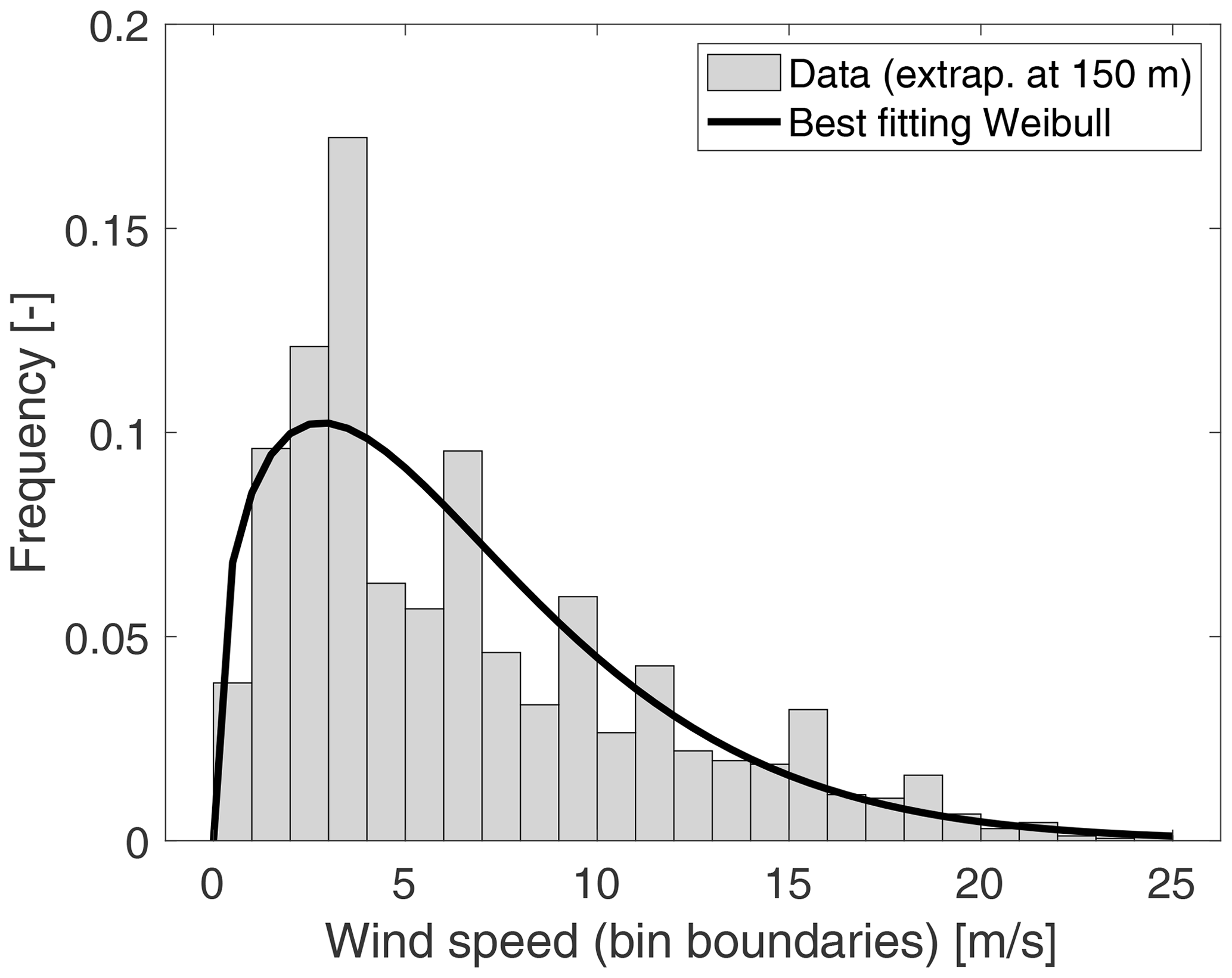
Figure 5Probability density function of the 1 h mean wind speed at 150 m at Marignane Weather Station, obtained from data recorded between October 2019 and March 2019. The best-fitting Weibull distribution is obtained for a scale parameter of 7.17 and a shape parameter of 1.38.
There is no measurement of turbulence intensity at the site, so the Normal Turbulence Model (NTM) is used. The characteristic standard deviation of the wind speed is given by
where U150 is the mean wind speed at 150 m, and Iref=0.12, which is appropriate for onshore class C turbines but conservative for offshore turbines with similar characteristics.
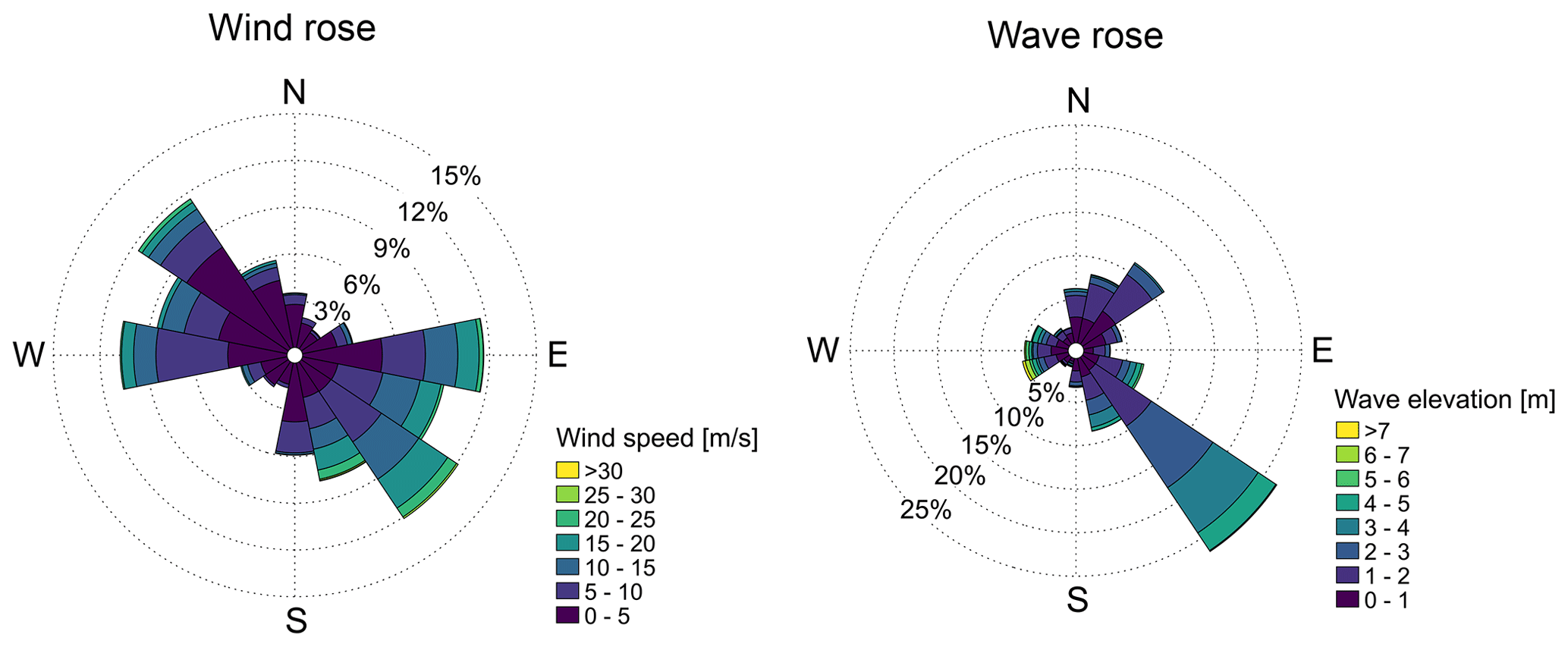
Figure 6 shows the wind rose from the records. The wind speeds were extrapolated to their value at 150 m by means of Eq. (6). Figure 6 also shows the rose of the direction from which the wave came. Waves come from the SE most of the time, while it is equally probable to have wind from the SE and NW, suggesting that the assumption of wind–wave alignment is not representative of this site.
In the Coupled-S model, the wave elevation Hs is assumed to depend linearly on the wind speed:
Coefficients in the expression were obtained from the linear regression of wave height and 150 m mean wind speed data.
The wind–wave conditions for the Coupled-S simulations for the Gulf of Fos site are reported in Table B1. Environmental conditions for the Coupled-C simulations are obtained applying the clustering algorithm of Sect. 2.1.4 to the dataset of five-dimensional vectors with . The 36 conditions identified by the clustering algorithm are reported in Table B2.
In this section, we show the results of the four simulation scenarios described in Sect. 2.1. Key parameters for analyzing the impact of waves and platform motions on the wind turbine energy production are the time-averaged value of the generated power (), the wind turbine power curve (a function of wind speed), and the annual energy production (AEP). Before reporting the results of the Harm-M, Harm-W, Coupled-S, and Coupled-C simulations, we show the influences of the peak-shaving control strategy and platform mean tilt (Sect. 3.1) and the wind shear and turbulence (Sect. 3.2) on the wind turbine power curve.
3.1 Influences of peak-shaving control and platform mean tilt
Figure 7 shows how the power curves of the NREL 5 MW and the IEA 15 MW with steady non-sheared wind change due to the use of a peak-shaving routine in the wind turbine controller and due to the presence of a floating foundation compared to a bottom-fixed one. The power curves were obtained from time-domain simulations in OpenFAST by averaging the instantaneous power over 900 s after it had reached a steady state for each wind speed. The OpenFAST models for these simulations are equivalent to those for the Harm-W scenario but with still water.
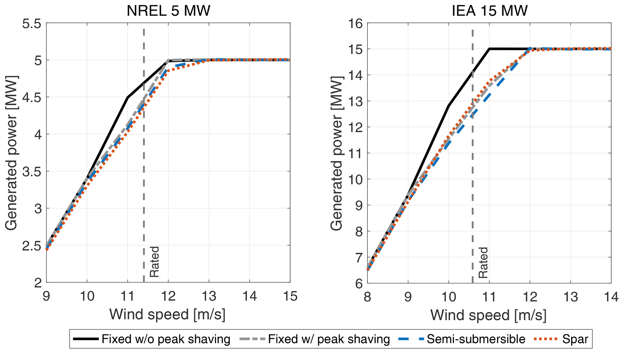
Figure 7Steady-state power curves of the NREL 5 MW and IEA 15 MW wind turbines with a fixed, a semi-submersible, and a spar foundation. The power curve near the rated wind speed is influenced by the peak-shaving control strategy (which reduces the conversion efficiency, making the turbine work far from its aerodynamically optimal operating point) and the use of a floating foundation (which is responsible for a large rotor tilt angle and a consequent reduction in the rotor area projected onto the plane normal to the wind). Peak shaving is used in all floating wind turbines. “w/” means “with”; “w/o” means “without”.
The peak-shaving routine reduces the turbine power near the rated wind speed because the turbine does not work at the power-optimal operating point when the blade pitch is different than the fine pitch. The reduction due to peak shaving in the bottom-fixed turbines is up to 8.9 % for the NREL 5 MW and 11 % for the IEA 15 MW.
When the turbine is on top of a floating foundation, the thrust force results in a mean tilt rotation of the structure and a reduction in the rotor area projected onto the vertical plane. The four floating wind turbines have a maximum mean tilt of 3–4° near the rated wind speed, and the consequent maximum reduction in generated power compared to the case with a fixed tower bottom and with peak shaving is 2 % for the 5 MW semi-submersible, 3 % for the 5 MW spar, 2.7 % for the 15 MW semi-submersible, and 2.7 % for the 15 MW spar.
3.2 Influences of wind shear and turbulence
The met-ocean database at our disposal does not provide any information about the vertical profile of mean wind speed and the turbulence intensity, so the wind shear and turbulence were selected for the Coupled-S and Coupled-C simulations based on standards. This procedure is commonly used in the early stages of floating offshore wind projects when detailed measurements of wind parameters at a given site are not available.
The effect of wind shear is assessed from power curves derived with the same method used to obtain the power curves in Sect. 3.1 but by considering a vertically sheared wind instead of a spatially uniform one. The vertical profile of wind speed is obtained by means of Eq. (6), fixing the reference height at that of the wind turbine hub and changing the exponent α to control the amount of shear. Figure 8 shows how the power curves of the four floating wind turbines change for several values of α. The shear exponent influences the wind turbine power curve in the below-rated region: the rotor-averaged wind speed decreases for higher values of α and the turbine produces less power. Above the rated wind speed, the turbine power is saturated and is not affected by α.
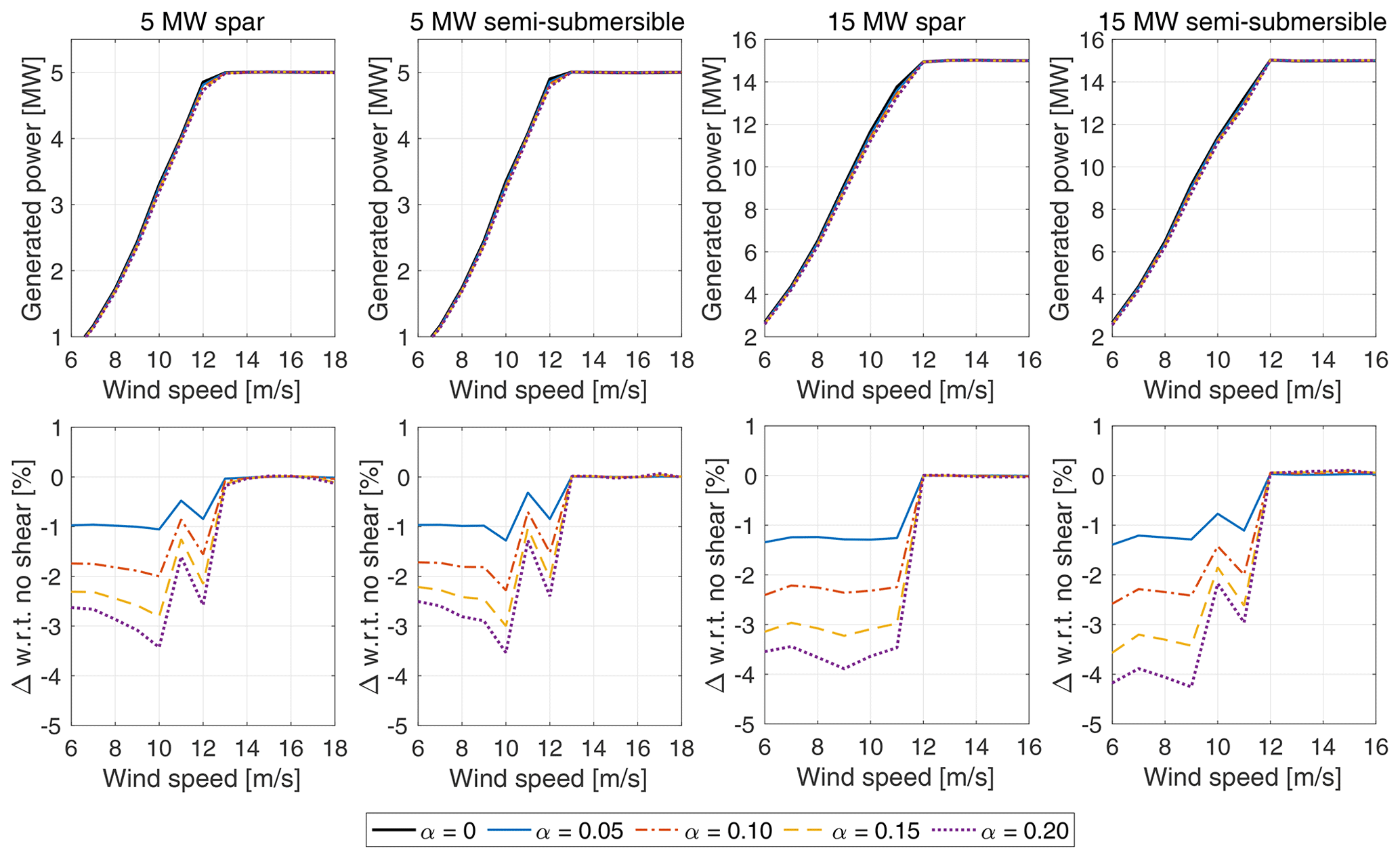
Figure 8Effect of wind shear on the four floating wind turbines. Power curves and percent variations of the power curve with respect to the case with no shear (α=0) are shown.
The effect of turbulence intensity is evaluated by simulating the wind turbine with no waves and the wind speeds in Table B1 and by changing Iref in the NTM of Eq. (7). Every wind condition was simulated for 3 h after a pre-simulation time of 3200 s that was needed to account for transients. In Fig. 9, we see that in the case with Iref=0.06, the power is lower than that obtained with steady wind for below-rated wind speeds. A further increase in turbulence brings higher power near the cut-in and lower power close to the rated wind speed. As explained by St. Martin et al. (2016), near the rated wind speed, the turbine controller adjusts the blade pitch to counteract rotor overspeed driven by wind gusts. Since the controller does not react instantly to the rotor speed and the blade pitch cannot go below 0°, the average blade pitch with turbulence and a near-rated wind speed can be different from its power-optimal value, which is used instead in the steady-wind case.
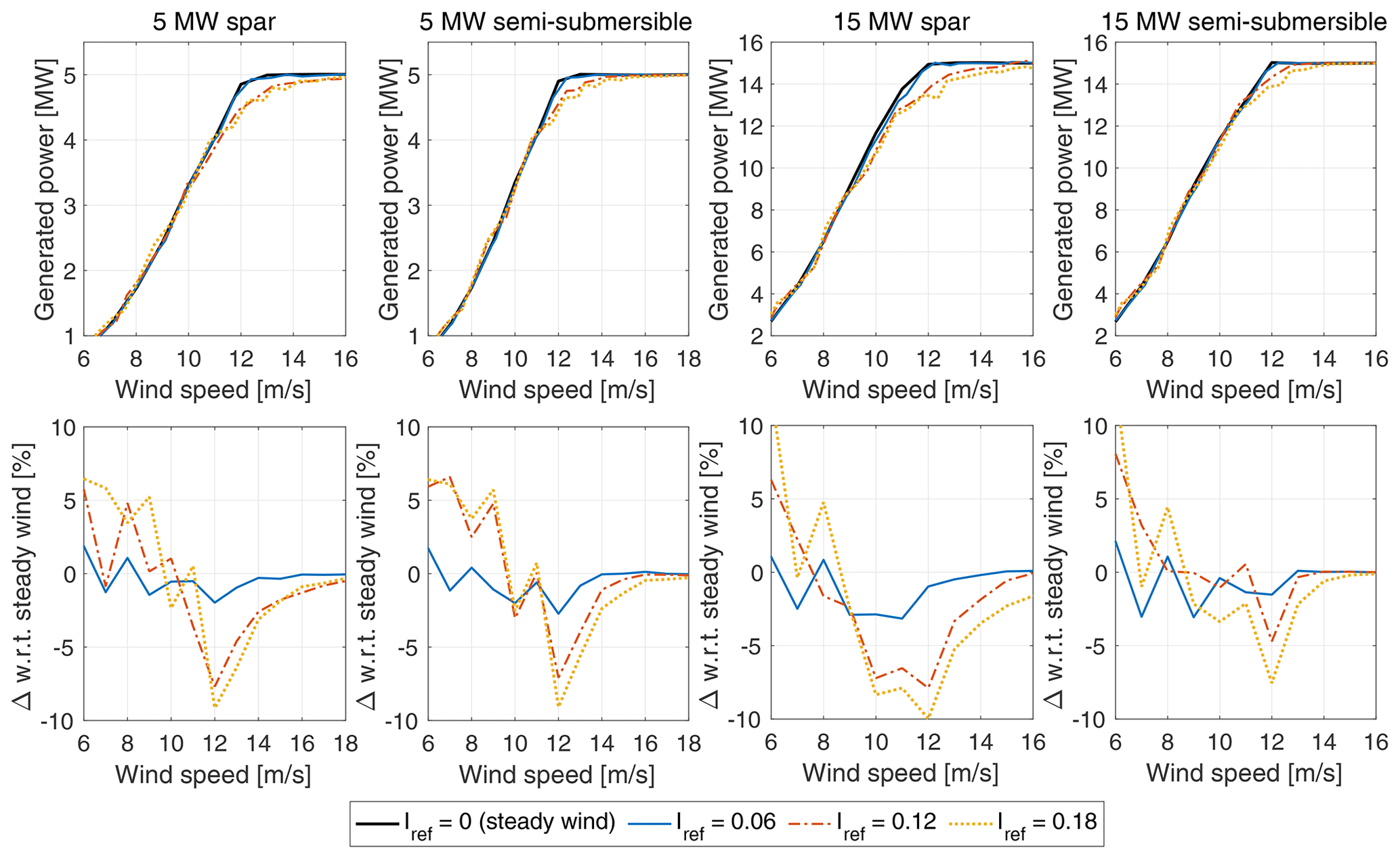
Figure 9Effect of turbulence intensity on the four floating wind turbines. Power curves and percent variations of the power curve with respect to the case with steady wind are shown.
We estimate that the uncertainty in wind shear and turbulence intensity occurs mostly in the below-rated region, and it may result in variations of the power curve of up to 10 %. This is in agreement with the results reported by St. Martin et al. (2016), who calculated turbulence-dependent power curves for a 1.5 MW wind turbine installed at the US Department of Energy National Wind Technology Center.
3.3 Power response to prescribed platform motion
To begin the discussion of Harm-M simulation results and to make a contact point with the analytical model of Eqs. (3) and (4), in Fig. 10 we show the time series of power generated by the IEA 15 MW with a prescribed surge motion of 1.5 m amplitude and 0.2 Hz frequency; the prescribed motion can be considered the first-order response to a wave with a period of 5 s. The time series shown in Fig. 10, as well as other results reported in this section, have been obtained with the Harm-M modeling approach described in Sect. 2.1.1. In Fig. 10, two steady and uniform wind conditions are examined: one in the below-rated region with a wind speed of 9 m s−1, and one with an above-rated wind speed of 15 m s−1. In the 9 m s−1 case, the fixed turbine has an average production of 9.4 MW, which is increased to 10.1 MW when the platform undergoes harmonic surge motion (+7.5 %). In the above-rated operating condition, motion has a weaker influence on the power production, which changes from 15 MW for the fixed turbine to 14.9 MW when the platform moves (−1 %).
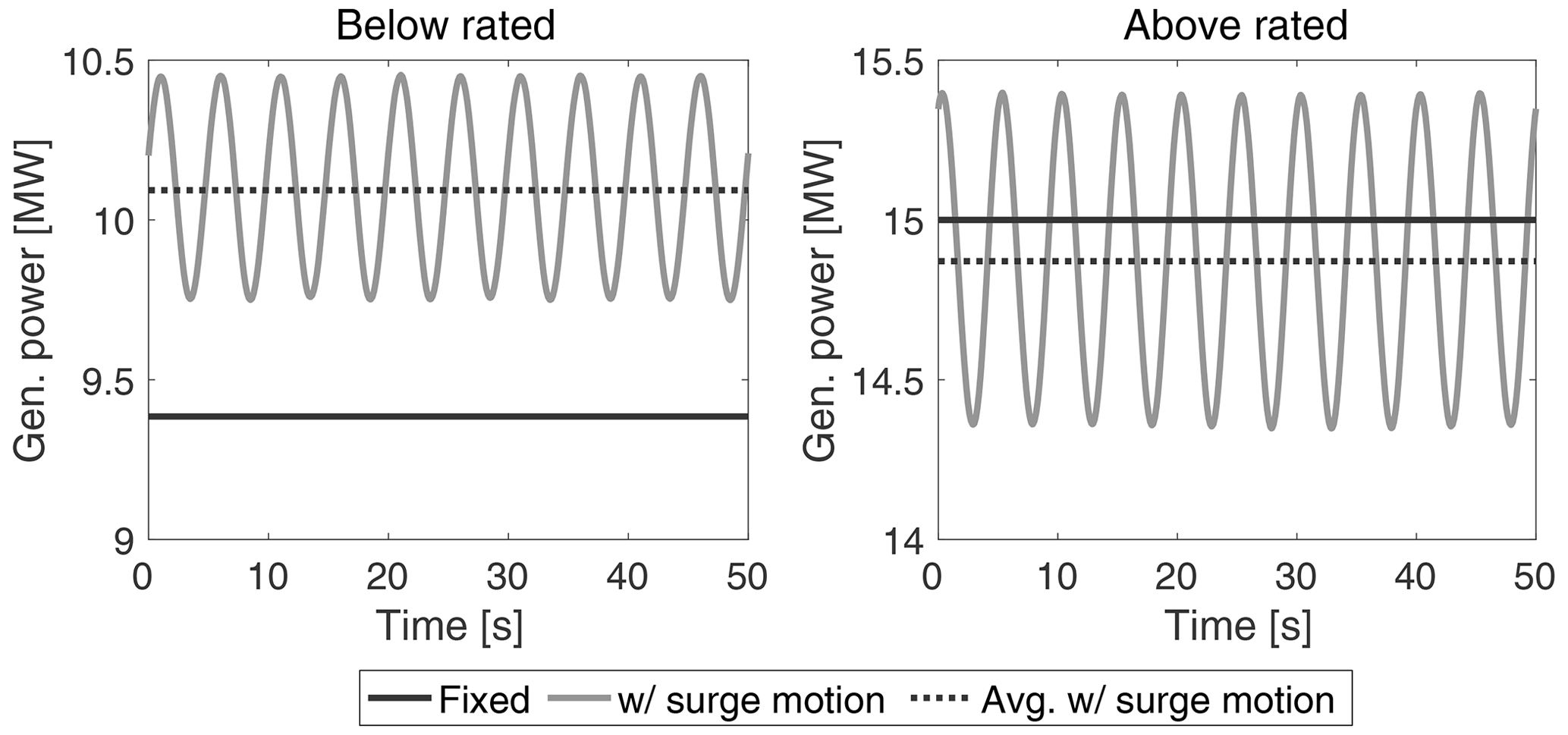
Figure 10Power generated by the IEA 15 MW with a below-rated wind speed of 9 m s−1 and an above-rated wind speed of 15 m s−1 when the tower bottom was fixed and with (“w/”) prescribed platform surge motion of 1.5 m amplitude and 0.2 Hz frequency.
Figure 11 shows the of the NREL 5 MW and the IEA 15 MW computed from Harm-M simulations with surge and pitch motions and a wind speed of 9 m s−1. In Fig. 11, is normalized by the power of the fixed wind turbine. The average power output increases with increasing frequency and amplitude of platform motion. Movements in the surge or pitch directions give an apparent wind at the rotor, which causes an increase in average generated power as explained by the analytical model of Eq. (3): the increment is proportional to the amplitude of the apparent wind speed variations at the hub, which is equal to Ur,h=ωmAm in the case of surge and Ur,h=ωmAmhh in the case of pitch, where hh is the distance of the hub from the center of pitch rotation for the platform (i.e., the tower base in this case).
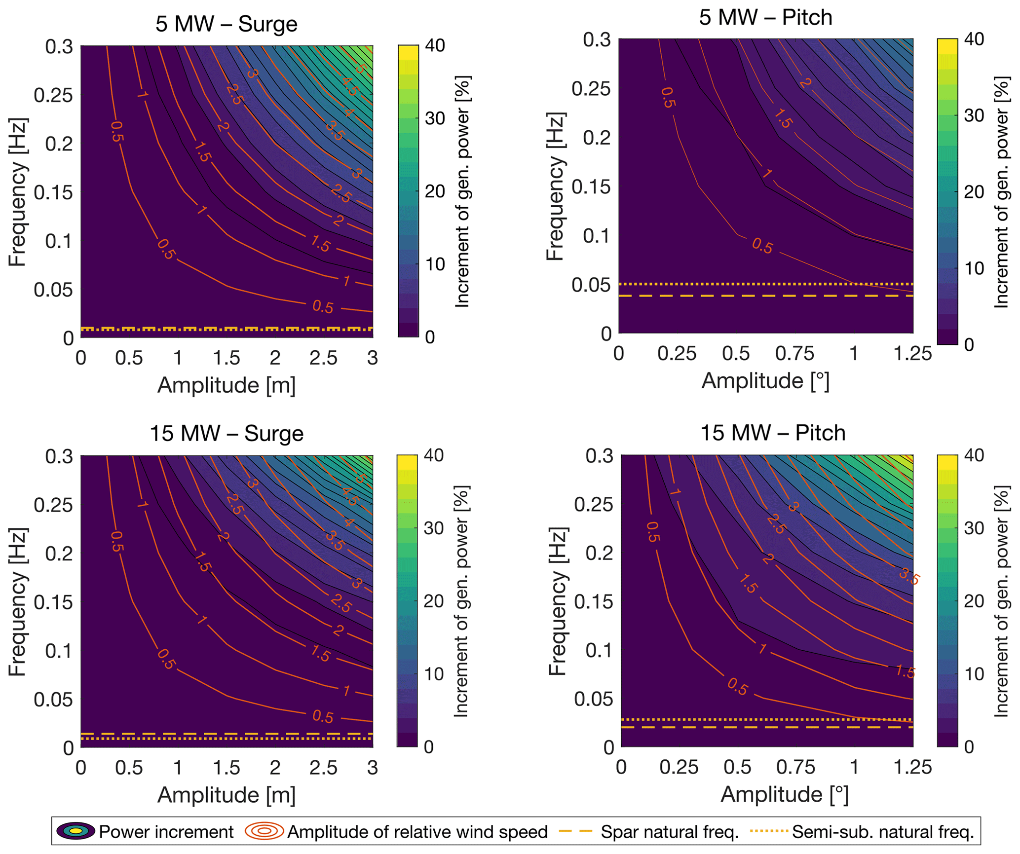
Figure 11Increment of the average generated power of the NREL 5 MW and the IEA 15 MW with prescribed motion of the platform in the surge and pitch directions and a below-rated wind speed of 9 m s−1. The generated power is normalized by the power of the fixed wind turbine. The “amplitude of relative wind speed” is the amplitude of the apparent wind speed at the hub due to platform motion (Ur,h); horizontal lines mark the natural frequency of the floating platform corresponding to the direction of prescribed motion (see Table 3).
In the surge case, the apparent wind is uniform across the rotor and equal to Ur,h, whereas in the pitch case, it is higher than Ur,h in the upper portion of the rotor disk and lower in the lower portion. If we compare surge and pitch motion cases that have similar Ur,h, the mean power is slightly higher in the case of pitch motion, and this is attributed to the higher amplitude of wind speed oscillations in the upper part of the rotor. The increment of generated power with surge motion is similar for the two wind turbines. On the other hand, for pitch motion of equal amplitude, the 15 MW turbine reaches a higher maximum power. This occurs because Ur,h is higher for the 15 MW than for the 5 MW turbine since hh is greater in the 15 MW wind turbine. For example, referencing Fig. 11, we see that with a pitch motion of Am=1° and fm=0.2 Hz, the increment of for the 5 MW is 4.4 % and Ur,h=2.0 m s−1, while for the 15 MW turbine, the increment of is 9.3 % and Ur,h=3.3 m s−1.
in the above-rated region is slightly lower than the rated power regardless of the tower base motion. With a wind speed of 9 m s−1, the variations in generated power due to harmonic motion in the sway, heave, roll, and yaw directions for all motion frequencies and amplitudes we investigated are between −0.3 % and +0.4 %.
Harm-M simulations, which simplify the platform kinematics to a large extent, show that a wind turbine operating at a below-rated wind speed produces more power when the rotor moves cyclically in the wind direction, and the increment is due to the energy in the apparent wind. This is in agreement with the analytical model of Eq. (3) and with the results of Amaral et al. (2022) and Cottura et al. (2022), which were obtained with comparable approaches. Figure 11 shows that the power only increases significantly for motions with a much higher frequency than the platform surge and pitch modes of the four floating wind turbines. With the Harm-W, Coupled-S, and Coupled-C simulations, which gradually introduce complexity and realism into the modeling of floating wind turbines, we will show that these power increments are not achieved in practice.
3.4 Power response with regular waves
The Harm-W simulations introduce the response of floating platforms to regular waves into the analysis. Results presented in this section are obtained with the modeling approach and considering the values of wave height and frequency reported in Sect. 2.1.2. Every regular wave condition was simulated for 3000 s, and the first 200 s were discarded in the post-processing to remove transients.
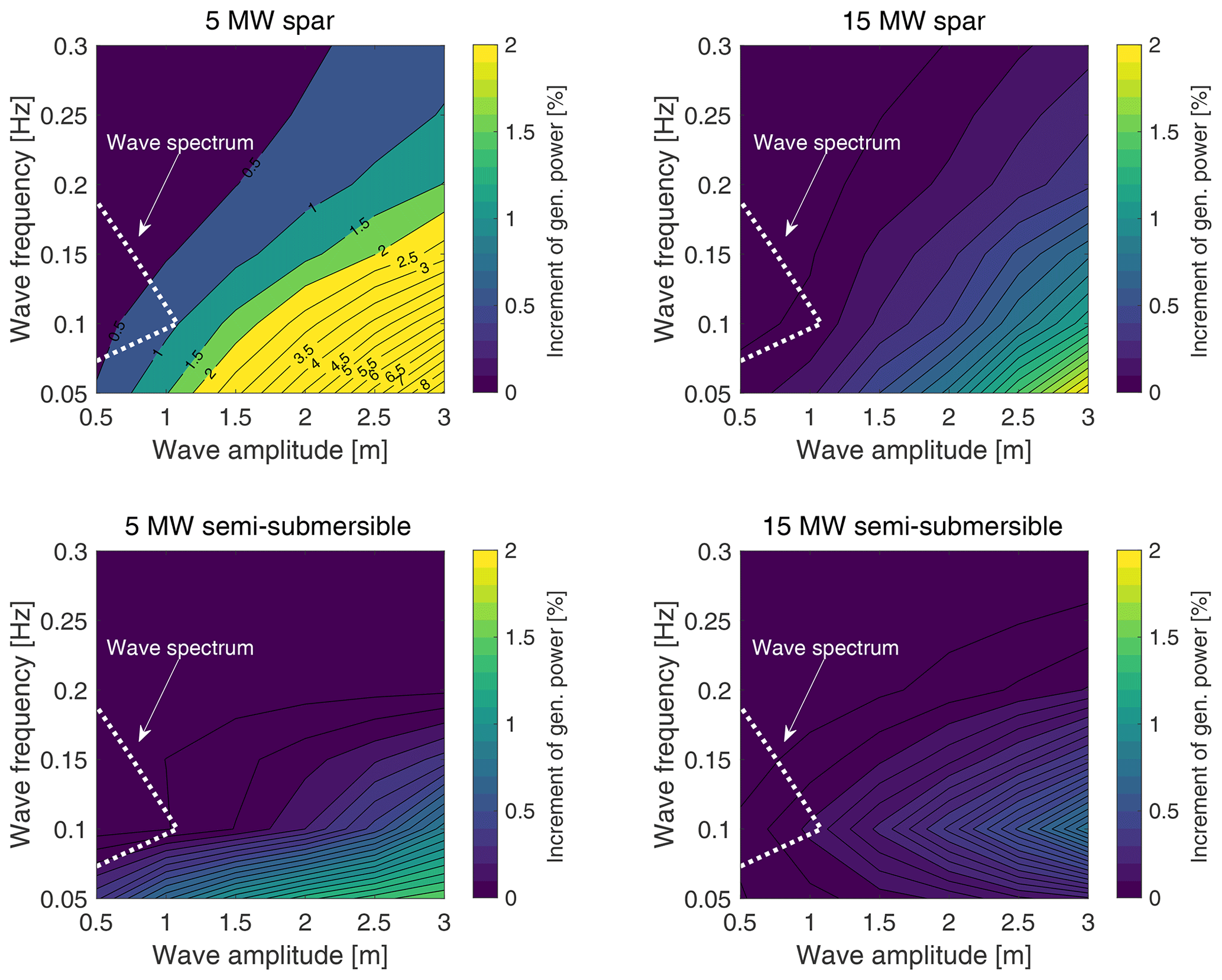
Figure 12Increments of the average power generated by the four floating wind turbines with wind and waves aligned to the platform's main axis and a below-rated wind speed of 9 m s−1. The generated power is normalized by the turbine power with no waves. The dotted line corresponds to the wave spectrum with Hs=4 m and Tp=9 s. The increment of the generated power for the 5 MW spar (indicated by labels on the contour lines) is above 2 %, which is the upper limit for the other three floating wind turbines.
Figure 12 shows for the four platforms with wind and waves aligned to the platform's main axis and a wind speed of 9 m s−1. We see that wave excitation increases the generated power for all platforms; the 5 MW spar has the largest increment, and the 15 MW semi-submersible has the smallest. In all turbines, the power increment is proportional to the wave amplitude. In a first approximation, platform motion due to wave excitation is linearly proportional to wave height; therefore, bigger waves result in greater movements of the wind turbine hub in the along-wind direction, which leads to a higher mean power output through the mechanism explained in Eq. (3) and with the Harm-M simulations.
Except for the VolturnUS, the power increment is inversely proportional to wave frequency for a given wave amplitude. This result, which appears to contradict the Harm-M results, is justified if we take into account the dynamic response to wave excitation of the platforms. Lower-frequency waves excite the FOWTs closer to their natural frequencies, resulting in larger movements. In the 15 MW semi-submersible case, the maximum power increment is found to occur at 0.1 Hz due to the platform's hydrodynamic characteristics.
In the Harm-W analysis, the 5 MW spar wind turbine has the largest increment of generated power: it reaches almost 10 % with a wave amplitude of 3 m and a frequency of 0.05 Hz. This large increment, which is not seen for other platforms, is likely due to the coupled surge and pitch motions that occur at relatively high frequency and involve large hub movements. The surge motion with 3 m waves of 0.05 Hz frequency is over 3 m in amplitude for the 5 MW spar, whereas it is lower than 1 m for all other turbines. Comparing the increments of for the two turbine sizes and the same floater type, we see that the power gains for the 5 MW turbines are generally higher than those for their 15 MW counterparts. This is due to the fact that the platform modes are at lower frequencies in the 15 MW FOWTs and the motion due to the first-order wave load is milder.
Figure 12 shows that large-amplitude, low-frequency waves can increase the power output of floating wind turbines. However, these power gains are only achieved in a real scenario if waves with these characteristics exist. The dashed region in Fig. 12 corresponds to a wave spectrum that can occur at the Gulf of Fos site. The wave spectrum is obtained from the wave height PSD computed according to the JONSWAP model of Hasselmann et al. (1973) with Hs=4 m and Tp=9 s. This is the most severe sea state recorded in the dataset at our disposal and has rather high waves with a low period, which is the condition required to increase power production. It is clear that wave excitation is not powerful enough to generate a meaningful increase in the generated power. Depending on the installation site, it is possible that the floating wind turbine may encounter a harsher sea during its lifetime, but the probability that this will occur with wind speeds lower than the rated one is generally low.
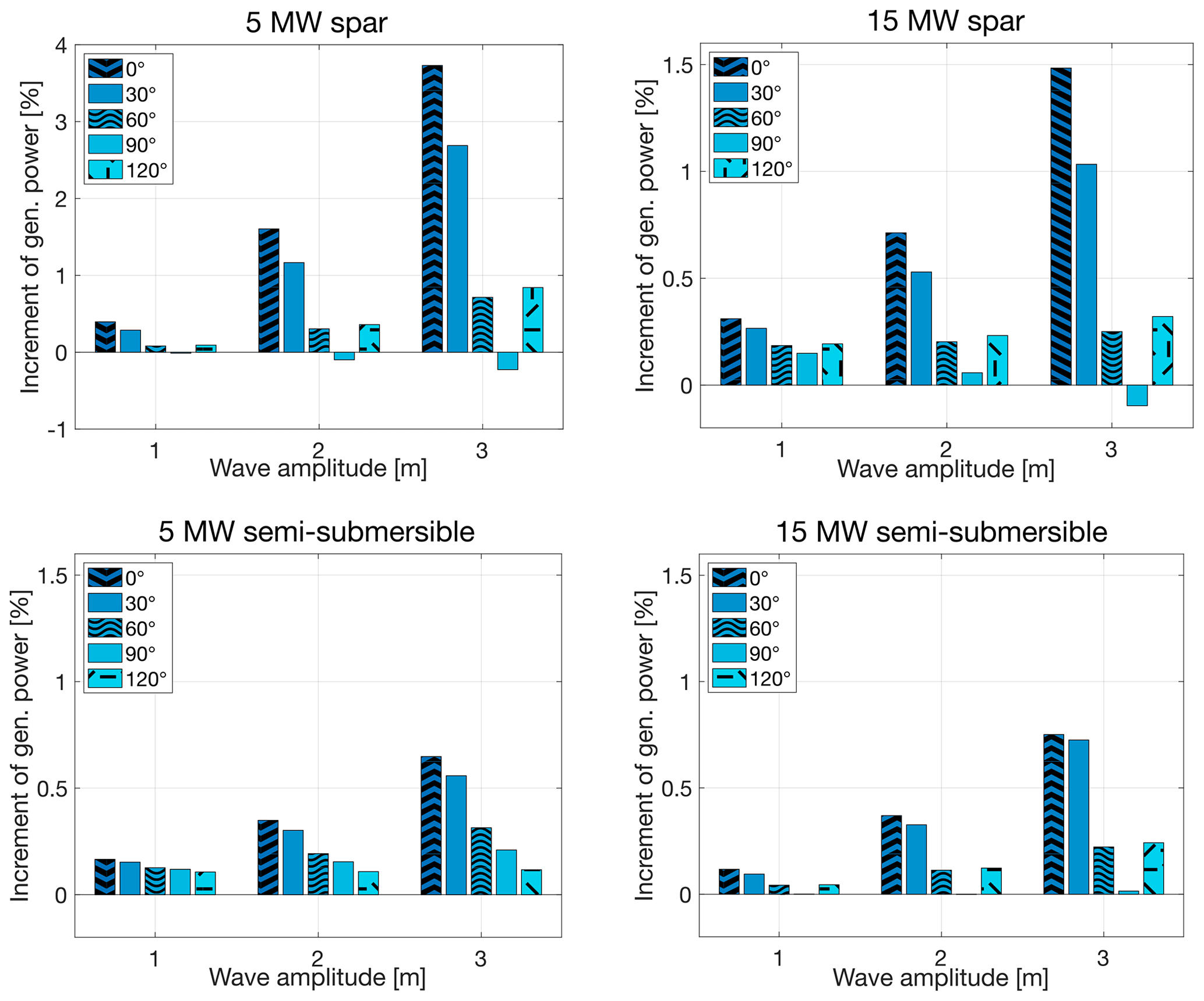
Figure 13Increments of the power generated by the four floating wind turbines due to harmonic waves; a below-rated wind speed of 9 m s−1, regular waves of 0.1 Hz frequency, and five values of the misalignment angle γ were considered.
To investigate the influence of wind–wave directionality, we calculated the values of the four floating wind turbines for a below-rated wind speed of 9 m s−1, regular waves of 0.1 Hz, three wave heights , and five directions from which the waves originate (), while in all cases. The results are reported in Fig. 13 and show that the largest power output gain is always achieved when the wind and waves are aligned because the waves force the platform to move in the wind direction. Conversely, when the waves are perpendicular to the wind, motions in the sway and roll directions are excited, and these have a negligible effect on the generated power. When the waves are perpendicular to the platform's main axis (γ=90°), the increment of is minimized (it is close to zero). This trend is seen for three values of wave amplitude, and a similar result is obtained with waves of 0.05 Hz frequency (not shown here for brevity).
Simulations with the Harm-M and the Harm-W models demonstrate it is necessary to have large-amplitude along-wind motions to increase the mean generated power. However, in normal operating conditions, these gains are unlikely to be achieved: the large-motion condition conflicts with the current design practice of floaters and wind turbines, which tries to minimize the floating wind-turbine movements to reduce mechanical loads, reduce material usage, and increase fatigue life.
3.5 Power response with stochastic wind and waves
A full picture of the energy conversion process of a floating wind turbine is gained with the Coupled-S and Coupled-C simulations, which consider realistic stochastic wind and waves. In our study, the Coupled-C scenario is the most faithful representation of the environmental conditions of the studied sea area since it reproduces the mutual relationship between wind and waves based on recorded met-ocean data. The key parameter we use to understand the impact of waves on the wind turbine power production in the Coupled-S and Coupled-C scenarios is the AEP presented in Sect. 3.5.2. Before discussing the AEP estimates, in Sect. 3.5.1 we delve into the physics of the power generation process: we examine the effects of wave excitation and wind–wave misalignment on hub motion, on the rotor's local inflow, and on changes in wind turbine power.
3.5.1 Wind turbine power, local inflow of the rotor, and along-wind motions
Figure 14 shows the variation of the average generated power of the four floating wind turbines in the Coupled-S and Coupled-C scenarios with respect to the steady-wind no-wave cases of Fig. 7. To emphasize the effect of wind turbulence alone, we introduce a case with a fixed foundation and turbulent wind (Iref=0.12) into the comparison.
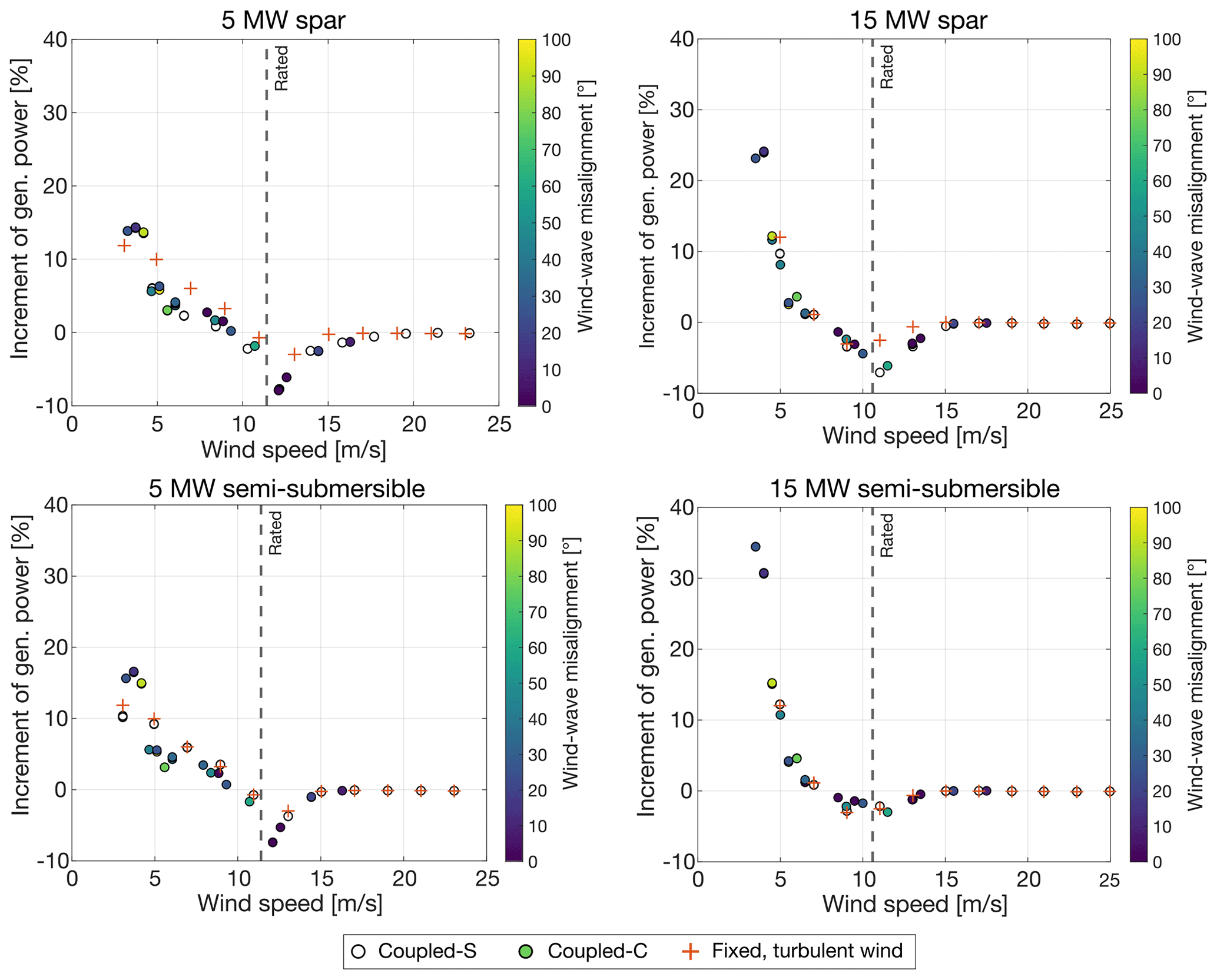
Figure 14Increments of the average power generated by the four floating wind turbines in the Coupled-S and Coupled-C scenarios with respect to the steady-wind no-wave cases. Markers of the Coupled-C cases are colored according to the absolute value of the wind–wave misalignment angle . The fixed-foundation, turbulent-wind case is included in the comparison to show the effect of wind turbulence.
For the fixed wind turbines, the effect of wind turbulence is to increase power at low wind speeds and to decrease it around the rated wind speed, as already commented in relation to Fig. 9. The trend is similar with floating foundations and waves. Moreover, the mean power generated with wind–wave misalignment of any amount is very close to the mean power generated with aligned wind and waves.
To clarify the impacts of wind, waves, and rigid-body movements on the energy conversion process occurring at the wind turbine rotor, we examine the hub motions of the four floating wind turbines. As discussed in Eq. (2), the hub motion contributes to the apparent wind speed experienced by the rotor and hence to the generated power. Two below-rated wind speeds, 5 and 9 m s−1, are considered: in these wind conditions, the wave spectrum has similar parameters in the Coupled-S and Coupled-C cases, but in the Coupled-C environment, the waves are not aligned to the wind direction and cause cross-wind motions (see Tables B1 and B2).
Figure 15 shows the structural velocity of the hub in the along-wind direction (positive downwind) for the four floating wind turbines and compares it with the time series of wind speed at the hub height. For all floating wind turbines and in every simulation scenario, hub structural velocity, which is mostly due to rigid-body platform motion, has variations that barely reach 1 m s−1 and, in most cases, are below 0.5 m s−1 in amplitude. At the same time, wind fluctuations have amplitudes of 2–3 m s−1. The apparent wind speed seen by the hub is the sum of the wind speed and hub structural velocity; thus, in all four floating wind turbines, wind gusts are responsible for the largest fraction of its variation.
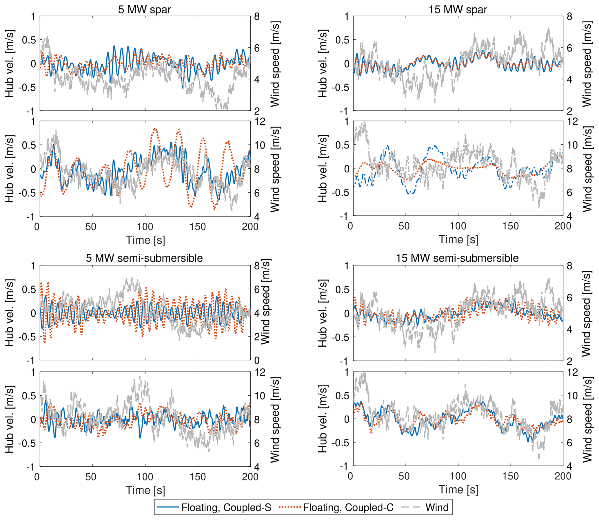
Figure 15The along-wind structural velocity of the hub is compared to the wind speed at hub height for the four floating wind turbines. (a, b, e, f) Mean wind speed of 5 m s−1. (c, d, g, h) Mean wind speed of 9 m s−1.
The sum of the wind speed and the structural velocity of the blades results in the rotor-averaged wind speed Vr,avg examined in Fig. 16 together with the time series of Pg, considering the same wind speeds and wave conditions as in Fig. 15. The parameter Vr,avg is computed by averaging the local relative velocity at the blade sections used in the aerodynamic model of OpenFAST. It is an indicator of the energy available for the rotor that can be converted into electric power, and – as shown in Eqs. (2) and (3), where Vr=Vr,avg – the fluctuating component of this parameter may lead to increased generated power.
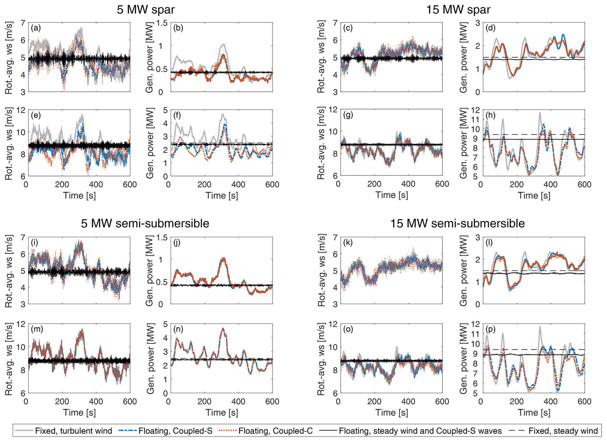
Figure 16Effect of wind turbulence and waves on the power conversion process in the four floating wind turbines. Time series of the rotor-averaged wind speed (ws) and generated power are shown for (a–d, i–l) a mean wind speed of 5 m s−1 and (e–h, m–p) a mean wind speed of 9 m s−1.
In all four FOWTs, the average power with steady wind is lower with a floating foundation and waves than with a fixed foundation, so the energy of the waves is not enough to compensate for the reduction in projected rotor area due to the floating-platform mean tilt. With stochastic wind, Vr,avg and Pg have low-frequency fluctuations that are significantly larger than those due to waves only (as seen in the cases with steady wind and Coupled-S waves); the low-frequency fluctuations of Vr,avg are mainly due to changes in wind speed caused by turbulence on the blades. As seen in Fig. 16, the impact of wind turbulence on the kinetic energy of the wind experienced by the rotor and hence on the generated power is dominant over the effect of waves, and, in Fig. 16, low-frequency variations in Vr,avg are highly correlated with variations in Pg. Time series of Pg in Coupled-C cases, where misaligned waves excite cross-wind platform motions, are very similar to those in the corresponding Coupled-S cases. This further supports the idea that platform movements due to waves have a negligible effect on the wind turbine power output.
At 5 m s−1, wind fluctuations increase , which is higher than in the steady-wind case, as discussed in Fig. 9. This effect of turbulence vanishes for higher wind speeds, and in turbulent wind cases with a 9 m s−1 mean wind speed, is slightly lower than it is with steady wind: this is clearly seen in Fig. 16h and p. In all cases in Fig. 16, the average power generated with a floating platform and waves is slightly lower than that generated with a fixed tower bottom. In the 5 MW semi-submersible FOWT, Pg for the Coupled-S case overlaps with Pg for the fixed case with turbulent wind, and the two time series have very close average values. The reduction in for the 5 MW semi-submersible is negligible compared to the fixed case because the 5 MW semi-submersible has the smallest mean tilt among the four FOWTs. The 5 MW spar has the largest mean tilt (e.g., at 9 m s−1, the 5 MW spar has a mean tilt of 3°, whereas the 5 MW semi-submersible has a mean tilt of 1.2°), and in Fig. 16b and c, it shows a significant reduction in compared to the fixed case. The two 15 MW floating wind turbines are in between the 5 MW spar and the 5 MW semi-submersible.
The results in Fig. 16 can be connected to those obtained with the Harm-M simulations examining FOWT motion in the frequency domain. Figure 17 shows the spectra of platform surge, platform pitch, and hub longitudinal motions obtained in Coupled-S simulations; that is, when wind and waves are aligned to the main axis of the platform and produce the maximum displacements in the wind direction. According to the Harm-W simulations of Fig. 13, this condition is the most favorable for achieving a higher rotor power. The spectra with 9 m s−1 mean wind speed, the same wind speed examined in Fig. 11 for the Harm-M simulations, are highlighted in blue. For all floating wind turbines, the maximum amplitude of motion corresponds with the natural frequencies of platform surge and pitch. The 5 MW spar has the maximum motion amplitude of all the FOWTs: the surge peak amplitude is 3.4 m at 0.01 Hz and the pitch peak amplitude is 0.57° at 0.01 Hz; their composition gives a peak hub displacement of 4.8 m. Compared to Fig. 11, these motions give a relative wind speed lower than 0.5 m s−1 at the hub, which is not enough to cause meaningful increments of generated power. In the wave frequency range (0.1–0.2 Hz), the motion spectra of Fig. 17 are generally lower than 0.1 m and 0.1° for platform surge and pitch and lower than 0.1 m for hub displacement: when compared to Fig. 11, these motion amplitudes are again not enough to significantly increase the rotor's average power.
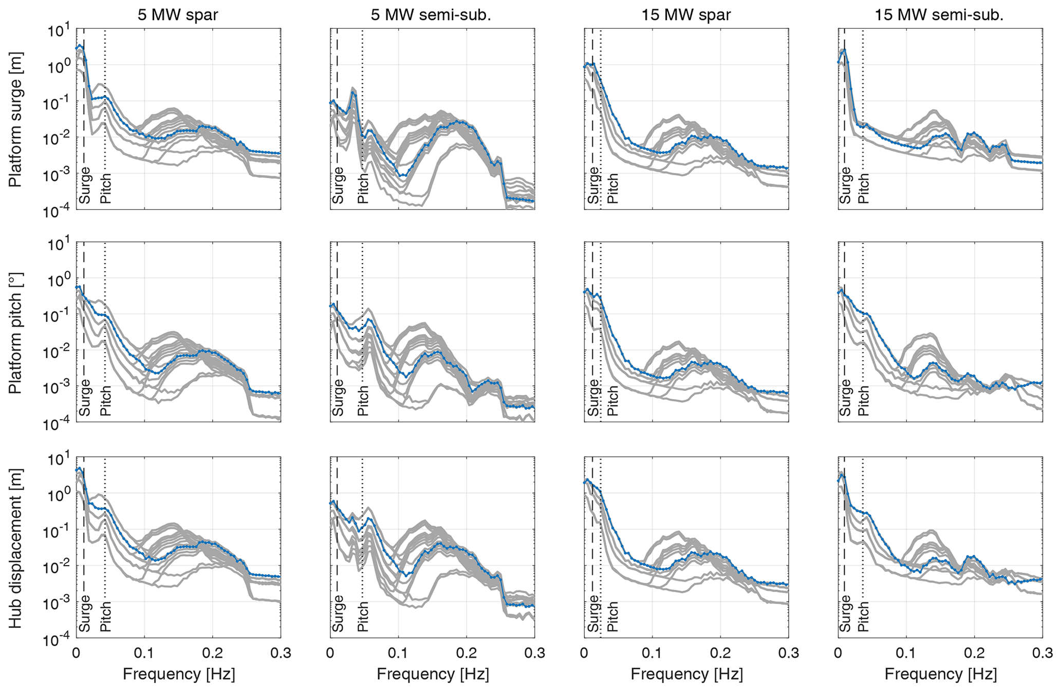
Figure 17Spectra of platform surge, platform pitch, and hub longitudinal motions in Coupled-S simulations with below rated wind speeds (i.e., up to 11 m s−1 for the 5 MW floating wind turbines and up to 9 m s−1 for the 15 MW floating wind turbines). Spectra from simulations with 9 m s−1 mean wind speed, Hs=2 m, Tp=5 s are highlighted in blue. Vertical lines mark the natural frequencies of the platform surge and pitch modes of the floating wind turbines with still air (see Table 3).
3.5.2 Site-specific power curves and AEP
Information about the power generated by the four floating wind turbines is now summarized with site-specific power curves and AEP estimates computed with the algorithm described in Appendix C.
Figure 18 shows the site-specific power curves from Coupled-S and Coupled-C simulations of the four FOWTs and of the fixed-tower-bottom case. The fixed case has the same turbulent wind as in the spar and semi-submersible cases and adopts the same control strategy for the floating wind turbines.
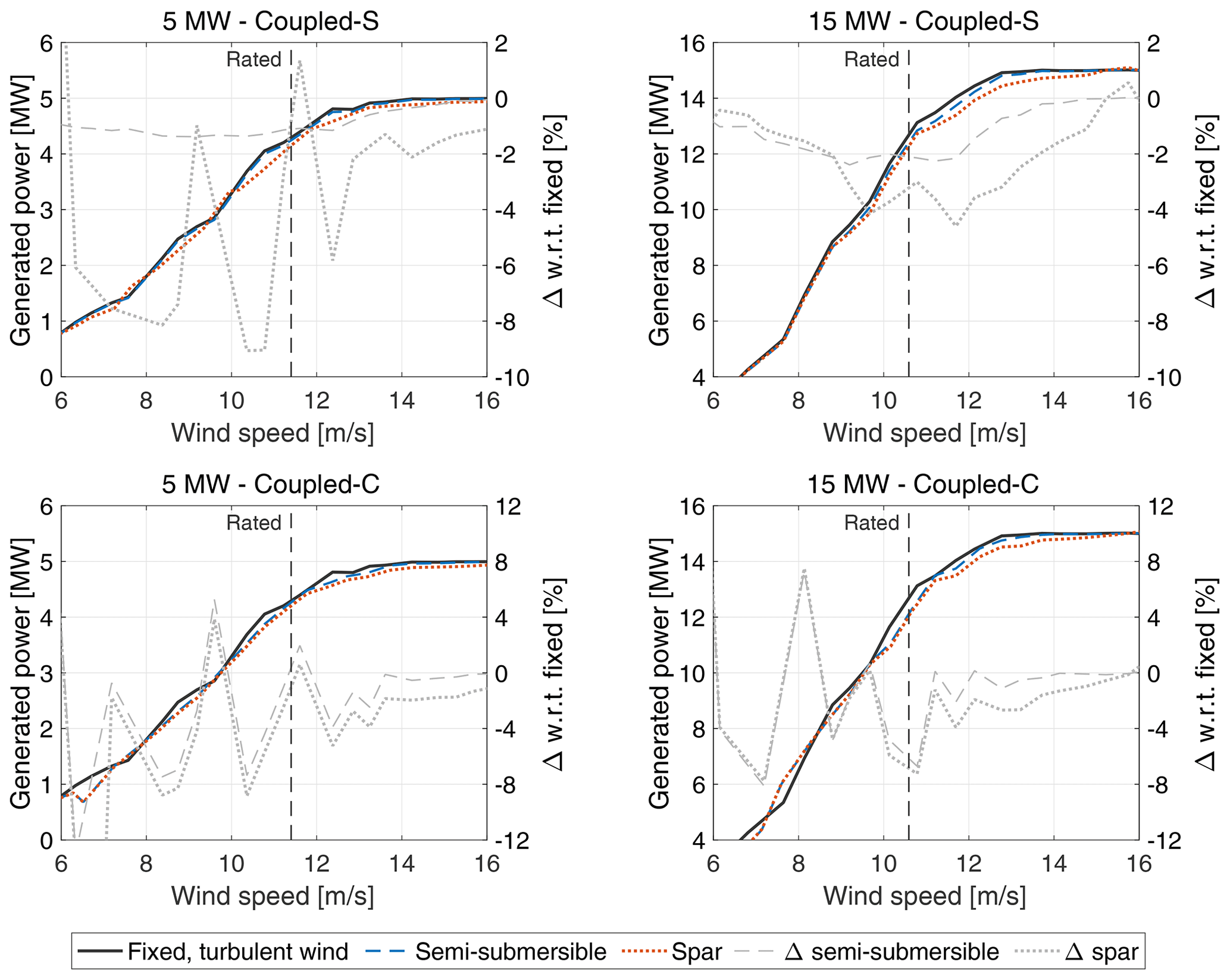
Figure 18Site-specific power curves of the NREL 5 MW and IEA 5 MW wind turbines with fixed, semi-submersible, and spar foundations, and the percent variations of the power generated in the floating case compared to the fixed-tower-base case with turbulent wind (Δ).
With a floating foundation and stochastic waves, the power curve is generally lower than in the fixed case, especially in the below-rated region. Above the rated wind speed, the power of the floating wind turbine increases and reaches the same value as in the fixed case. In Coupled-S simulations of the 15 MW floating wind turbines and the 5 MW semi-submersible, the power loss with respect to the fixed case increases across the partial-load region up to the rated wind speed and becomes negligible in the full-load region, where the turbine power is saturated at its rated value. In these three cases, the power loss could be ascribed to the platform's mean tilt, because it follows the same trend as the turbine thrust curve (see Fig. 3) and is minimum for the 5 MW semi-submersible, which has the smallest pitch rotation among the FOWTs we studied.
There are no clear trends for the Coupled-C cases and the Coupled-S simulations of the 5 MW spar, especially for low wind speeds. In some wind speed bins, the Coupled-C power curves are above the fixed case. At 9 m s−1, the power curve of the 5 MW spar obtained from Coupled-C simulations is above that of the fixed case, but the time series of generated power in Fig. 16n show that the spar's average power is lower than that obtained with a fixed foundation. Thus, fluctuations in the power curves obtained from Coupled-C simulations are attributed to the methodology used for computing the site-specific power curve rather than the wind turbine response. Although we have not analyzed the sensitivity of the power curve to the number of clusters, we expect these oscillations to become smaller upon increasing the number of simulations and extracting the environmental conditions from a larger dataset that covers the operating range of wind speeds for the wind turbines more uniformly.
The AEP estimates for the four FOWTs with different models for the wind and waves are reported in Fig. 19. In all cases, the energy production with a floating foundation and waves is lower than in the fixed-tower-bottom case. Simulations with regular waves show that the increment of generated power due to wave-driven motion is around 0.1 % for a typical wave spectrum, and this small gain is not enough to offset the power loss due to platform tilt, as commented in relation to Fig. 7. The AEP obtained from simulations with wind–wave misalignment (Coupled-C) is close to that for the case with aligned wind and waves (Coupled-S). The small differences are attributed to the AEP estimation algorithm rather than different physics of the power conversion process of the floating wind turbines, as already observed regarding the power curves in Fig. 18.
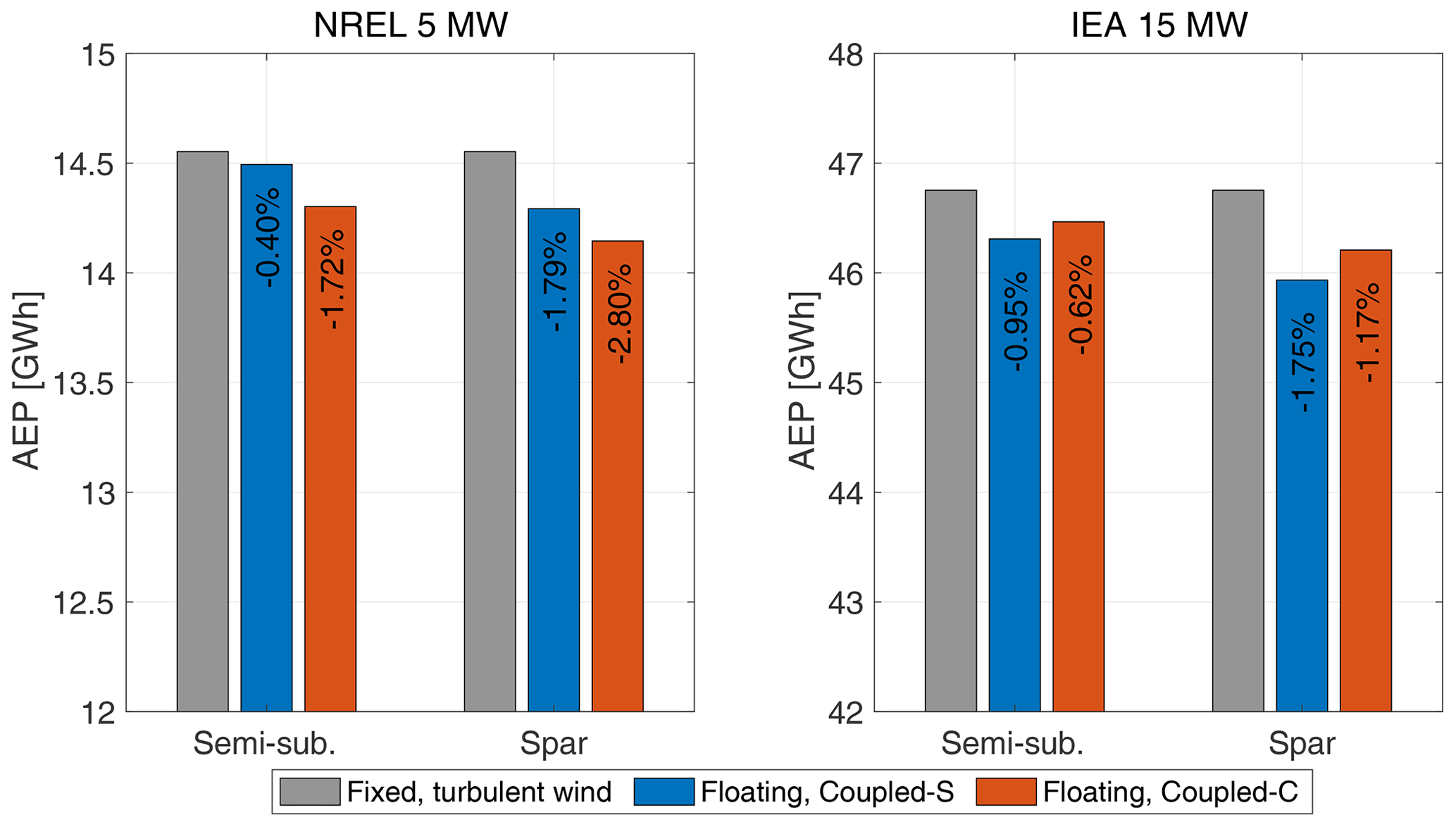
Figure 19Annual energy production (AEP) of the NREL 5 MW and IEA 5 MW wind turbines with a fixed foundation and turbulent wind and with semi-submersible and spar foundations from the Coupled-S and Coupled-C simulation scenarios. The percent variation of AEP with respect to the fixed case is superimposed on the bar.
3.5.3 Concluding the analysis of results obtained with stochastic wind and waves
In realistic sea conditions, the action of waves does not significantly change the power generated by the four floating wind turbines (the object of this study) because it does not produce motions that are large enough. The energy yield of the FOWTs is lower than that of a bottom-fixed wind turbine; in particular, their power curve is reduced near the rated wind speed due to the platform's mean tilt. In realistic environmental conditions, the power output is driven by wind turbulence rather than waves.
Variations in the power curve due to uncertainty in the shear exponent and turbulence intensity are comparable to the power losses of a FOWT with respect to a bottom-fixed turbine. A recent study by Wiley et al. (2023) showed that the standard deviation of the turbulent wind speed is the parameter with the highest impact on rotor loads and global motions for the DeepCwind semi-submersible, confirming that a detailed knowledge of the wind environment is needed when assessing the response of floating wind turbines.
The dataset at our disposal covers a shorter time span than what is normally considered in the energy assessment of a wind power plant; wind speed values are low for an area generally seen as quite favorable for the development of floating wind projects, possibly due to the Marignane Weather Station being located onshore. This is likely to affect the AEP value, which may underestimate the true energy potential of the sea site. However, our interest was primarily in understanding the impact of waves and platform motions on energy production. The dataset covers a winter period when waves were generally stronger, so the conclusions are expected to be valid even if a larger dataset is analyzed.
A floating wind-turbine rotor normally undergoes large movements permitted by the platform compliance, and it may operate differently than that with a fixed foundation. Waves introduce energy into the system, forcing the rotor to move, which can potentially increase the generated power.
To understand how waves and platform dynamics impact the power production of a floating wind turbine, we carried out multi-physics simulations of four FOWTs of 5–15 MW with spar and semi-submersible support structures. We used four simulation models of increasing complexity: they gradually move from simple analytical calculations to a nonlinear aero-servo-hydro-elastic model that reproduces a realistic scenario with stochastic wind and waves in the Mediterranean Sea.
The main findings of this research are as follows:
-
Large along-wind motions can increase the rotor power, but these movements are prevented by the current design philosophy of semi-submersible and spar platforms.
-
The energy production of the floating wind turbines examined in this study is lower than that for a fixed turbine in the same wind conditions.
-
Wind modeling is more important than wave modeling for the correct estimation of floating wind-turbine power production, at least for a site with met-ocean conditions similar to those we considered here.
Concerning the first finding, we have shown that power gains due to wave-driven motions in the wind direction (e.g., surge and pitch) are possible only at below-rated wind speeds because power is saturated by the wind turbine controller in the above-rated region. The increment in average power is proportional to the amplitude and frequency of platform movement, and it is maximum when the rotor moves in the along-wind direction. However, with wind–wave misalignment, part of the wave energy is used to excite cross-wind motions that do not contribute to increasing the energy of the flow available for the rotor to convert into electric power. Taking into account the hydrodynamic loads and the platform's dynamic response, we see that wave excitation is generally not strong enough to achieve the large movements required to yield a significant rise in generated power. Large movements at the linear wave frequency are required to increase the power output of a wind turbine rotor. These do not occur in practice because the maximum-amplitude motions are at the rigid-body motion modes of the platform, which are generally at very low frequencies. The decision to design platforms to have low-frequency modes tends to minimize the motions due to wave loads, reducing the dynamic excitation of the turbine components and extending the fatigue life of the system as much as possible.
Concerning the second finding, the lower performance of a floating wind turbine compared to a bottom-fixed one is mainly due to the mean tilt of the floater caused by a combination of the thrust force and high compliance of floating foundations, which reduces the rotor area projected onto the vertical plane. It should be verified that these findings are also valid for tension-leg platform (TLP) systems, which tend to have higher-frequency and smaller motions.
About the third finding, we realized that information about wind parameters, such as shear and turbulence, might be scarce in the early stages of floating wind projects, and this lack of data should be addressed properly when evaluating the energy potential of a floating wind plant. At the same time, the energy evaluation process can be simplified by considering a reduced number of wave conditions. Future work should check that this is also true for sites characterized by different environmental parameters (e.g., stronger waves).
The wind turbine power curve is influenced significantly by the wind turbine control strategy and floater restoring characteristics, which must be modeled in energy calculations. This is important not only for the individual machines but also for wind farm modeling, where the power curve is often used in engineering tools as a simplified representation of the turbine response (e.g., in FLOw Redirection and Induction in Steady state (FLORIS), NREL, 2023a).
As we have shown, it is not possible to exploit the energy of waves with the current technology of semi-submersible and spar-buoy floating wind turbines that do not integrate wave energy conversion devices. Future designs may explore the trade-off between loads and increased power to see if it is feasible to leverage the peculiar physics of a floating rotor to harvest more energy and further decrease the cost of the floating wind technology.
The K-means algorithm introduced in Sect. 2.1.4 is applied to the dataset for the Gulf of Fos site presented in Sect. 2.3 to extract M=5 clusters. The number of clusters used in this example is lower than the number used in Coupled-C simulations, where M=36, to facilitate the interpretation of the result.
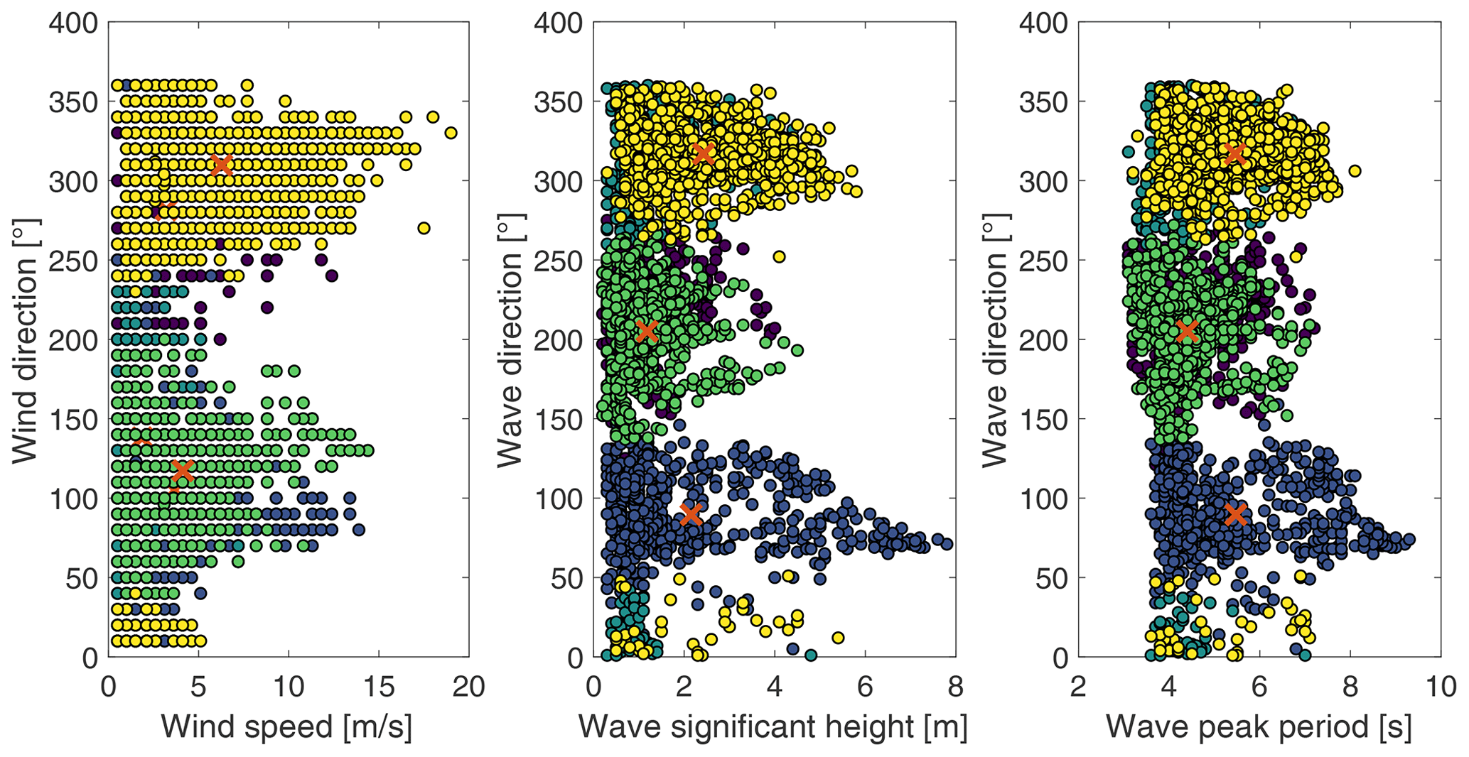
Figure A1Met-ocean data (wind speed, wind direction, significant wave height, peak wave period, and wave direction) for the Gulf de Fos site are divided into clusters with the K-means algorithm. Data points are colored according to the cluster to which they are assigned, and cluster centroids are marked by × symbols.
Figure A1 shows the KMA output. Each dot is one of the 3362 conditions in the dataset represented in the five-dimensional space . Dots are colored according to the cluster to which they are assigned by the KMA. It is clear that dots of the same color share similar features; for example, yellow dots are sea states with , . In the KMA, each cluster is represented by its centroid, marked by a × symbol.
As we can see, if the number of clusters is too low (as in this example), the centroids do not accurately represent the dataset features. In the yellow cluster, there is no distinction of wind speed, wave height, or wave period, each of which spans a large range and is sometimes quite far from the cluster centroid.
The environmental conditions used for the Coupled-S simulations are summarized in Table B1, and those used for the Coupled-C simulations are given in Table B2.
Table B1Wind and wave conditions in the Coupled-S simulations (“ws” is wind speed).
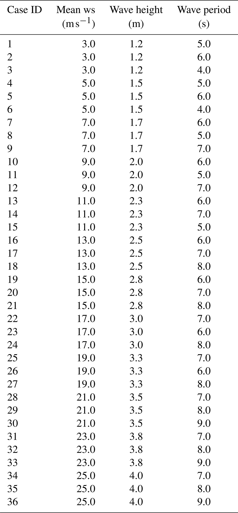
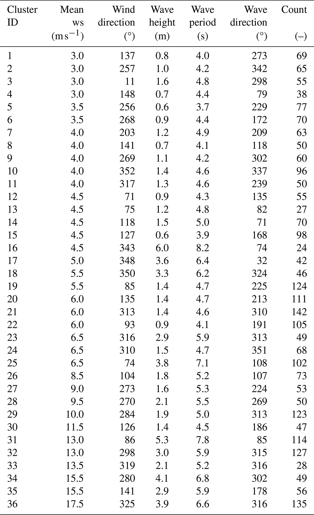
Table B2Wind and wave conditions identified via K-means clustering and used for the Coupled-C simulations (“ws” is wind speed; “Count” is the number of data points in each cluster).
The site-specific power curve and the AEP are derived according to the algorithm of the IEC 61400-12 standard (International Electrotechnical Commission, 2022) and based on time series of hub-height wind speed and generated power.
The time series of wind speed and generated power are divided into 10 min segments and, for each segment, the mean value is computed. The dataset of 10 min mean values is sorted using the method of bins:
-
The wind speed range is divided into contiguous 0.5 m s−1 bins centered on multiples of 0.5 m s−1, and the dataset is distributed into the bins according to the 10 min mean wind speed.
-
The dataset must cover a wind speed range extending from 1 m s−1 below the cut-in to 1.5 times the wind speed at 85 % of the wind turbine's rated power. Otherwise, for pitch-controlled wind turbines such as the NREL 5 MW and the IEA 15 MW, the power curve is considered complete when the rated power is reached and the average power does not change by more than 0.5 % of the power, or 5 kW, for three consecutive wind speed bins. If the power curve does not include data up to the cut-out wind speed, the power curve is extrapolated from the maximum complete wind speed to the cut-out wind speed.
-
The dataset is considered to be complete when each bin includes a minimum of 30 min of sampled data. For incomplete bins, the bin value is estimated by linear interpolation from the two adjacent complete bins.
The power curve (i.e., power as a function of wind speed) is determined based on the hub-height wind speed of each bin:
where Vi is the average wind speed in bin i, is the wind speed of data point j in bin i, and Ni is the number of 10 min data points in bin i. The power of each bin is
where Pi is the average power in bin i, is the power of data point j in bin i, and Ni is the number of 10 min data points in bin i. An example of a power curve obtained with the method of bins is reported in Fig. C1.
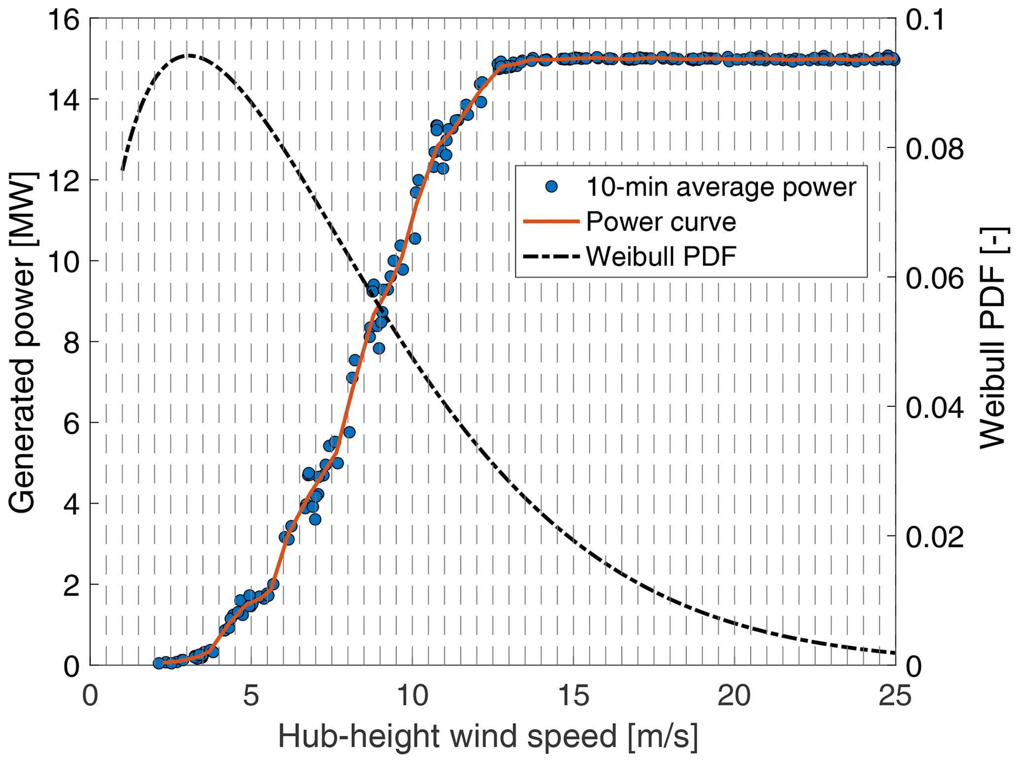
Figure C1Construction of the site-specific power curve from simulations of the Coupled-S and Coupled-C scenarios. Time series of generated power obtained from OpenFAST simulations are divided into 10 min sub-histories. The dots are the corresponding mean values.
The AEP is evaluated by combining the power curve obtained with the method of bins with the wind-speed frequency distribution as follows:
where AEP is the annual energy production, Nh=8760 is the number of hours in 1 year, N is the number of bins, Vi is the average wind speed in bin i, Pi is the average power of bin i, and F(Vi) is the site-specific Weibull cumulative probability distribution function for wind speed (i.e., the one in Fig. 5 for this paper). The summation in Eq. (C3) is initiated by setting and .
The OpenFAST models and the results of simulations can be accessed via Fontanella et al. (2024) (https://doi.org/10.5281/zenodo.10513599).
AF contributed to the conceptualization, investigation, methodology, software, visualization, and writing (original draft preparation). GC contributed to the conceptualization, investigation, methodology, software, and writing (original draft preparation). MDP contributed to the methodology, investigation, software, and writing (original draft preparation). SM contributed to the supervision, project administration, and writing (reviewing and editing). MB contributed to the conceptualization, funding acquisition, supervision, and writing (reviewing and editing).
The contact author has declared that none of the authors has any competing interests.
Publisher's note: Copernicus Publications remains neutral with regard to jurisdictional claims made in the text, published maps, institutional affiliations, or any other geographical representation in this paper. While Copernicus Publications makes every effort to include appropriate place names, the final responsibility lies with the authors.
This paper was edited by Maurizio Collu and reviewed by Rad Haghi and two anonymous referees.
Abbas, N. J., Zalkind, D. S., Pao, L., and Wright, A.: A reference open-source controller for fixed and floating offshore wind turbines, Wind Energ. Sci., 7, 53–73, https://doi.org/10.5194/wes-7-53-2022, 2022. a, b
Allen, C., Viselli, A., Dagher, H., Goupee, A., Gaertner, E., Abbas, N., Hall, M., and Barter, G.: Definition of the UMaine VolturnUS-S Reference Platform Developed for the IEA Wind 15-Megawatt Offshore Reference Wind Turbine, Technical Report NREL/TP-5000-76773, https://www.nrel.gov/docs/fy20osti/76773.pdf (last access: 31 March 2022), 2020. a
Allen, C., Viselli, A., Dagher, H., Goupee, A., Gaertner, E., Abbas, N., Hall, M., and Barter, G.: UMaine VolturnUS-S Reference Platform, https://github.com/IEAWindTask37/IEA-15-240-RWT/tree/master/OpenFAST (last access: December 2023), 2023. a
Amaral, R., Laugesen, K., Masciola, M., von Terzi, D., Deglaire, P., and Viré, A.: A frequency-time domain method for annual energy production estimation in floating wind turbines, J. Phys. Conf. Ser., 2265, 042025, https://doi.org/10.1088/1742-6596/2265/4/042025, 2022. a, b, c
Arthur, D. and Vassilvitskii, S.: K-Means: The Advantages of Careful Seeding, in: Proceedings of the Eighteenth Annual ACM-SIAM Symposium on Discrete Algorithms, SODA '07, Society for Industrial and Applied Mathematics, New Orleans, Louisiana, USA, 7–9 January 2007, 1027–1035, https://dl.acm.org/doi/10.5555/1283383.1283494 (last access: 22 June 2024), 2007. a
Bachynski, E. E., Kvittem, M. I., Luan, C., and Moan, T.: Wind-Wave Misalignment Effects on Floating Wind Turbines: Motions and Tower Load Effects, J. Offshore Mech. Arct., 136, 041902, https://doi.org/10.1115/1.4028028, 2014. a
Branlard, E., Shields, M., Anderson, B., Damiani, R., Wendt, F., Jonkman, J., Musial, W., and Foley, B.: Superelement reduction of substructures for sequential load calculations in OpenFAST, J. Phys. Conf. Ser., 1452, 012033, https://doi.org/10.1088/1742-6596/1452/1/012033, 2020. a
Campos, A., Molins, C., Gironella, X., and Trubat, P.: Spar concrete monolithic design for offshore wind turbines, P. I. Civil Eng.-Mar. En., 169, 49–63, https://doi.org/10.1680/jmaen.2014.24, 2016. a, b
Camus, P., Mendez, F. J., Medina, R., and Cofiño, A. S.: Analysis of clustering and selection algorithms for the study of multivariate wave climate, Coast. Eng., 58, 453–462, https://doi.org/10.1016/j.coastaleng.2011.02.003, 2011. a
Cioni, S., Papi, F., Pagamonci, L., Bianchini, A., Ramos-García, N., Pirrung, G., Corniglion, R., Lovera, A., Galván, J., Boisard, R., Fontanella, A., Schito, P., Zasso, A., Belloli, M., Sanvito, A., Persico, G., Zhang, L., Li, Y., Zhou, Y., Mancini, S., Boorsma, K., Amaral, R., Viré, A., Schulz, C. W., Netzband, S., Soto-Valle, R., Marten, D., Martín-San-Román, R., Trubat, P., Molins, C., Bergua, R., Branlard, E., Jonkman, J., and Robertson, A.: On the characteristics of the wake of a wind turbine undergoing large motions caused by a floating structure: an insight based on experiments and multi-fidelity simulations from the OC6 project Phase III, Wind Energ. Sci., 8, 1659–1691, https://doi.org/10.5194/wes-8-1659-2023, 2023. a
Clifton, A., Daniels, M. H., and Lehning, M.: Effect of winds in a mountain pass on turbine performance, Wind Energy, 17, 1543–1562, https://doi.org/10.1002/we.1650, 2014. a
Cottura, L., Caradonna, R., Novo, R., Ghigo, A., Bracco, G., and Mattiazzo, G.: Effect of pitching motion on production in a OFWT, Journal of Ocean Engineering and Marine Energy, 8, 319–330, https://doi.org/10.1007/s40722-022-00227-0, 2022. a, b, c
EMODnet: EMODnet Bathymetry World Base Layer, https://emodnet.ec.europa.eu/en/bathymetry (last access: 31 March 2022), 2023. a
Fleming, P. A., Peiffer, A., and Schlipf, D.: Wind Turbine Controller to Mitigate Structural Loads on a Floating Wind Turbine Platform, J. Offshore Mech. Arct., 141, 061901, https://doi.org/10.1115/1.4042938, 2019. a
Fontanella, A., Facchinetti, A., Di Carlo, S., and Belloli, M.: Wind tunnel investigation of the aerodynamic response of two 15 MW floating wind turbines, Wind Energ. Sci., 7, 1711–1729, https://doi.org/10.5194/wes-7-1711-2022, 2022. a
Fontanella, A., Colpani, G., De Pascali, M., Muggiasca, S., and Belloli, M.: OpenFAST models and simulation outputs to assess the impact of waves and platform dynamics on floating wind turbine energy production, Zenodo [code and data set], https://doi.org/10.5281/zenodo.10513599, 2024. a
France, M.: Mètéo-France. Gulf de Lion buoy, https://donneespubliques.meteofrance.fr/?fond=produit&id_produit=95&id_rubrique=32 (last access: 31 March 2022), 2022. a
Gaertner, E., Rinker, J. and. Sethuraman, L., Zahle, F., Anderson, B., Barter, G., Abbas, N., Meng, F., Bortolotti, P., Skrzypinski, W., Scott, G., Feil, R., Bredmose, H., Dykes, K., Shields, M., Allen, C., and Viselli, A.: Definition of the IEA 15-Megawatt Offshore Reference Wind Turbine, Tech. rep., National Renewable Energy Laboratory, https://www.nrel.gov/docs/fy20osti/75698.pdf (last access: 31 March 2022), 2020. a
Hall, M. and Goupee, A.: Validation of a lumped-mass mooring line model with DeepCwind semisubmersible model test data, Ocean Eng., 104, 590–603, https://doi.org/10.1016/j.oceaneng.2015.05.035, 2015. a
Hasselmann, K. F., Barnett, T. P., Bouws, E., Carlson, H. C., Cartwright, D. E., Enke, K., Ewing, J. A., Gienapp, H., Hasselmann, D. E., Kruseman, P., Meerburg, A., Müller, P. M., Olbers, D. J., Richter, K., Sell, W., and Walden, H.: Measurements of wind-wave growth and swell decay during the Joint North Sea Wave Project (JONSWAP), https://repository.tudelft.nl/islandora/object/uuid:f204e188-13b9-49d8-a6dc-4fb7c20562fc?collection=research (last access: 31 October 2023), 1973. a
International Electrotechnical Commission: Wind energy generation systems – Part 3-1: Design requirements for fixed offshore wind turbines, IEC 61400-3-1:2019, Tech. Rep. IEC 61400-12-1:2022, International Electrotechnical Commission, https://webstore.iec.ch/publication/29360 (last access: 31 March 2022), 2019. a
International Electrotechnical Commission: Wind energy generation systems – Part 12-1: Power performance measurements of electricity producing wind turbines, IEC 61400-12-1:2022, Tech. Rep. IEC 61400-12-1:2022, International Electrotechnical Commission, https://webstore.iec.ch/publication/68499#additionalinfo (last access: 31 March 2022), 2022. a
Jonkman, B., Mudafort, R. M., Platt, A., Branlard, E., Sprague, M., Jonkman, J., Ross, H., Hall, M., Vijayakumar, G., Buhl, M., Bortolotti, P., Ananthan, S., Schmidt, M., Rood, J., Damiani, R., Mendoza, N., Shaler, K., Housner, S., Bendl, K., Carmo, L., Quon, E., Phillips, M. R., Kusuno, N., and Salcedo, A. G.: OpenFAST/openfast: v3.4.1, https://doi.org/10.5281/zenodo.7632926, 2023. a
Jonkman, B. J.: Turbsim User's Guide: Version 1.50, https://doi.org/10.2172/965520, 2009a. a
Jonkman, J.: Definition of the Floating System for Phase IV of OC3, NREL/TP-500-47535, https://www.nrel.gov/docs/fy10osti/47535.pdf (last access: 31 March 2022), 2009b. a
Jonkman, J., Butterfield, S., Musial, W., and Scott, G.: Definition of a 5 MW reference wind turbine for offshore system development, NREL/TP-500-38060, https://www.nrel.gov/docs/fy09osti/38060.pdf (last access: 31 March 2022), 2009. a
Krieger, A., Ramachandran, G. K. V., Vita, L., Alonso, P. G., Almeria, G. G., Berque, J., and Aguirre, G.: D7.2 Design Basis, LIFES50+ Deliverable, https://lifes50plus.eu/wp-content/uploads/2015/11/D72_Design_Basis_Retyped-v1.1.pdf (last access: 31 March 2022), 2015. a
Mahfouz, M. Y., Molins, C., Trubat, P., Hernández, S., Vigara, F., Pegalajar-Jurado, A., Bredmose, H., and Salari, M.: Response of the International Energy Agency (IEA) Wind 15 MW WindCrete and Activefloat floating wind turbines to wind and second-order waves, Wind Energ. Sci., 6, 867–883, https://doi.org/10.5194/wes-6-867-2021, 2021. a, b, c, d
Martini, M., Guanche, R., Armesto, J. A., Losada, I. J., and Vidal, C.: Met-ocean conditions influence on floating offshore wind farms power production, Wind Energy, 19, 399–420, https://doi.org/10.1002/we.1840, 2016. a
Meteostat: Marseille – Marignane weather station, https://meteostat.net/en/station/07650?t=2023-06-12/2023-06-19 (last access: 31 March 2022), 2022. a
Molins, C., Trubat, P., and Mahfouz, M. Y.: UPC – WINDCRETE OpenFAST model 15 MW FOWT – Grand Canary Island, https://doi.org/10.5281/zenodo.4322446, 2020. a
NREL: FLORIS, https://github.com/NREL/floris, last access: 21 September 2023a. a
NREL: ROSCO, Version 2.8.0, https://github.com/NREL/ROSCO (last access: 30 September 2023), 2023b. a
Patryniak, K., Collu, M., and Coraddu, A.: Rigid body dynamic response of a floating offshore wind turbine to waves: Identification of the instantaneous centre of rotation through analytical and numerical analyses, Renew. Energ., 218, 119378, https://doi.org/10.1016/j.renene.2023.119378, 2023. a
Renan dos Santos, C., Abdelmoteleb, S.-E., Mendoza, A. S. E., and Bachynski-Polić, E. E.: Control Considerations for Very Large Floating Wind Turbines, IFAC PapersOnLine, 55, 166–171, https://doi.org/10.1016/j.ifacol.2022.10.426, 2022. a
Robertson, A., Jonkman, J., Masciola, M., Song, H., Goupee, A., Coulling, A., and Luan, C.: Definition of the Semisubmersible Floating System for Phase II of OC4, NREL/TP-5000-60601, https://www.nrel.gov/docs/fy14osti/60601.pdf (last access: 31 March 2022), 2014. a
Schelbergen, M., Kalverla, P. C., Schmehl, R., and Watson, S. J.: Clustering wind profile shapes to estimate airborne wind energy production, Wind Energ. Sci., 5, 1097–1120, https://doi.org/10.5194/wes-5-1097-2020, 2020. a
St. Martin, C. M., Lundquist, J. K., Clifton, A., Poulos, G. S., and Schreck, S. J.: Wind turbine power production and annual energy production depend on atmospheric stability and turbulence, Wind Energ. Sci., 1, 221–236, https://doi.org/10.5194/wes-1-221-2016, 2016. a, b, c
van der Veen, G. J., Couchman, I. J., and Bowyer, R. O.: Control of floating wind turbines, in: 2012 American Control Conference (ACC), Montréal, Canada, 27–29 June 2012, 3148–3153, https://doi.org/10.1109/ACC.2012.6315120, 2012. a, b
Vanelli, T., Rinker, J., and Zalkind, D. S.: Aeroservoelastic stability of a floating wind turbine, J. Phys. Conf. Ser., 2265, 042001, https://doi.org/10.1088/1742-6596/2265/4/042001, 2022 a
van Kuik, G. A. M., Peinke, J., Nijssen, R., Lekou, D., Mann, J., Sørensen, J. N., Ferreira, C., van Wingerden, J. W., Schlipf, D., Gebraad, P., Polinder, H., Abrahamsen, A., van Bussel, G. J. W., Sørensen, J. D., Tavner, P., Bottasso, C. L., Muskulus, M., Matha, D., Lindeboom, H. J., Degraer, S., Kramer, O., Lehnhoff, S., Sonnenschein, M., Sørensen, P. E., Künneke, R. W., Morthorst, P. E., and Skytte, K.: Long-term research challenges in wind energy – a research agenda by the European Academy of Wind Energy, Wind Energ. Sci., 1, 1–39, https://doi.org/10.5194/wes-1-1-2016, 2016. a
Wiley, W., Jonkman, J., Robertson, A., and Shaler, K.: Sensitivity analysis of numerical modeling input parameters on floating offshore wind turbine loads, Wind Energ. Sci., 8, 1575–1595, https://doi.org/10.5194/wes-8-1575-2023, 2023. a
Wiser, R., Rand, J., Seel, J., Beiter, P., Baker, E., Lantz, E., and Gilman, P.: Expert elicitation survey predicts 37 % to 49 % declines in wind energy costs by 2050, Nature Energy, 6, 555–565, https://doi.org/10.1038/s41560-021-00810-z, 2021. a
- Abstract
- Introduction
- Methodology
- Results
- Conclusions
- Appendix A: Example of KMA clustering
- Appendix B: Wind and wave conditions from clustering
- Appendix C: Site-specific power curve and annual energy production
- Code and data availability
- Author contributions
- Competing interests
- Disclaimer
- Review statement
- References